EP3220799B1 - Anordnung einer medizinischen vorrichtung und zugehörige verfahren - Google Patents
Anordnung einer medizinischen vorrichtung und zugehörige verfahren Download PDFInfo
- Publication number
- EP3220799B1 EP3220799B1 EP15831025.0A EP15831025A EP3220799B1 EP 3220799 B1 EP3220799 B1 EP 3220799B1 EP 15831025 A EP15831025 A EP 15831025A EP 3220799 B1 EP3220799 B1 EP 3220799B1
- Authority
- EP
- European Patent Office
- Prior art keywords
- connector
- illumination
- medical device
- control unit
- endoscope
- Prior art date
- Legal status (The legal status is an assumption and is not a legal conclusion. Google has not performed a legal analysis and makes no representation as to the accuracy of the status listed.)
- Active
Links
Images


Classifications
-
- A—HUMAN NECESSITIES
- A61—MEDICAL OR VETERINARY SCIENCE; HYGIENE
- A61B—DIAGNOSIS; SURGERY; IDENTIFICATION
- A61B1/00—Instruments for performing medical examinations of the interior of cavities or tubes of the body by visual or photographical inspection, e.g. endoscopes; Illuminating arrangements therefor
- A61B1/00112—Connection or coupling means
- A61B1/00114—Electrical cables in or with an endoscope
-
- A—HUMAN NECESSITIES
- A61—MEDICAL OR VETERINARY SCIENCE; HYGIENE
- A61B—DIAGNOSIS; SURGERY; IDENTIFICATION
- A61B1/00—Instruments for performing medical examinations of the interior of cavities or tubes of the body by visual or photographical inspection, e.g. endoscopes; Illuminating arrangements therefor
- A61B1/00002—Operational features of endoscopes
- A61B1/00004—Operational features of endoscopes characterised by electronic signal processing
- A61B1/00006—Operational features of endoscopes characterised by electronic signal processing of control signals
-
- A—HUMAN NECESSITIES
- A61—MEDICAL OR VETERINARY SCIENCE; HYGIENE
- A61B—DIAGNOSIS; SURGERY; IDENTIFICATION
- A61B1/00—Instruments for performing medical examinations of the interior of cavities or tubes of the body by visual or photographical inspection, e.g. endoscopes; Illuminating arrangements therefor
- A61B1/00112—Connection or coupling means
- A61B1/00121—Connectors, fasteners and adapters, e.g. on the endoscope handle
- A61B1/00124—Connectors, fasteners and adapters, e.g. on the endoscope handle electrical, e.g. electrical plug-and-socket connection
-
- A—HUMAN NECESSITIES
- A61—MEDICAL OR VETERINARY SCIENCE; HYGIENE
- A61B—DIAGNOSIS; SURGERY; IDENTIFICATION
- A61B1/00—Instruments for performing medical examinations of the interior of cavities or tubes of the body by visual or photographical inspection, e.g. endoscopes; Illuminating arrangements therefor
- A61B1/00064—Constructional details of the endoscope body
- A61B1/0011—Manufacturing of endoscope parts
-
- A—HUMAN NECESSITIES
- A61—MEDICAL OR VETERINARY SCIENCE; HYGIENE
- A61B—DIAGNOSIS; SURGERY; IDENTIFICATION
- A61B1/00—Instruments for performing medical examinations of the interior of cavities or tubes of the body by visual or photographical inspection, e.g. endoscopes; Illuminating arrangements therefor
- A61B1/00112—Connection or coupling means
- A61B1/00121—Connectors, fasteners and adapters, e.g. on the endoscope handle
- A61B1/00126—Connectors, fasteners and adapters, e.g. on the endoscope handle optical, e.g. for light supply cables
-
- A—HUMAN NECESSITIES
- A61—MEDICAL OR VETERINARY SCIENCE; HYGIENE
- A61B—DIAGNOSIS; SURGERY; IDENTIFICATION
- A61B1/00—Instruments for performing medical examinations of the interior of cavities or tubes of the body by visual or photographical inspection, e.g. endoscopes; Illuminating arrangements therefor
- A61B1/04—Instruments for performing medical examinations of the interior of cavities or tubes of the body by visual or photographical inspection, e.g. endoscopes; Illuminating arrangements therefor combined with photographic or television appliances
- A61B1/05—Instruments for performing medical examinations of the interior of cavities or tubes of the body by visual or photographical inspection, e.g. endoscopes; Illuminating arrangements therefor combined with photographic or television appliances characterised by the image sensor, e.g. camera, being in the distal end portion
-
- A—HUMAN NECESSITIES
- A61—MEDICAL OR VETERINARY SCIENCE; HYGIENE
- A61B—DIAGNOSIS; SURGERY; IDENTIFICATION
- A61B1/00—Instruments for performing medical examinations of the interior of cavities or tubes of the body by visual or photographical inspection, e.g. endoscopes; Illuminating arrangements therefor
- A61B1/06—Instruments for performing medical examinations of the interior of cavities or tubes of the body by visual or photographical inspection, e.g. endoscopes; Illuminating arrangements therefor with illuminating arrangements
- A61B1/0661—Endoscope light sources
- A61B1/0684—Endoscope light sources using light emitting diodes [LED]
-
- A—HUMAN NECESSITIES
- A61—MEDICAL OR VETERINARY SCIENCE; HYGIENE
- A61B—DIAGNOSIS; SURGERY; IDENTIFICATION
- A61B1/00—Instruments for performing medical examinations of the interior of cavities or tubes of the body by visual or photographical inspection, e.g. endoscopes; Illuminating arrangements therefor
- A61B1/06—Instruments for performing medical examinations of the interior of cavities or tubes of the body by visual or photographical inspection, e.g. endoscopes; Illuminating arrangements therefor with illuminating arrangements
- A61B1/07—Instruments for performing medical examinations of the interior of cavities or tubes of the body by visual or photographical inspection, e.g. endoscopes; Illuminating arrangements therefor with illuminating arrangements using light-conductive means, e.g. optical fibres
Definitions
- the present disclosure relates generally to medical devices, and more particularly to medical device assemblies and related methods.
- aspects of the present disclosure may relate to single use, single connector medical devices connected to a single control unit, and related methods.
- Endoscopic visualization may be used to diagnose and/or treat any number of conditions in the gastric, pulmonary, and urologic tracts. Endoscopes may be used to not only navigate to a target site, but also to provide adequate visualization at the target site for diagnosis and/or treatment.
- Typical endoscopic systems may include a reusable endoscope, as well as separate pieces of capital equipment.
- the capital equipment of a traditional endoscopic system may include an image processing unit and a separate light source unit.
- glass fiber bundles may transmit light from the proximal end, where light may be introduced from the light source, to the distal end of the endoscope. This may have a number of disadvantages.
- a reusable endoscope may require cleaning/sterilization following every procedure. Every cleaning cycle may potentially lead to damage of the endoscope, possibly necessitating expensive repairs. In addition, there may be a risk of reusing incorrectly/insufficiently cleaned endoscopes.
- the endoscope may be connected to the capital equipment. That may entail making multiple connections: an electrical connection to transmit image or video signals from the endoscope to the image processing unit, and an illumination connection to transmit light from the light source to the endoscope. Establishing multiple connections may require more user interaction and setup time. Having multiple separate units of capital equipment may also require more space within a facility.
- US 2003/133011 A1 discloses a connector assembly for an endoscope apparatus, which includes a plug removably insertable in a receptacle.
- the plug has a molded body incorporating a light cable and an electrical connector in a fixed spatial relationship within the molded body.
- US 2005/197536 A1 discloses a video endoscope system including a reusable control cabinet and an endoscope that is connectable thereto.
- the endoscope may be used with a single patient and then disposed.
- the endoscope includes an illumination mechanism, an image sensor, and an elongate shaft having one or more lumens located therein.
- An articulation joint at the distal end of the endoscope allows the distal end to be oriented by the actuators in the control cabinet or actuators in a control handle of the endoscope. Fluidics, electrical, navigation, image, display and data entry controls are integrated into the system along with other accessories.
- US 2011/208004 A1 discloses an external endoscope light source system including light emitting diodes for providing a light output to an endoscope.
- the light is provided to a fiber optic cable for transmission to the endoscope.
- a fiber optic receives a portion of the light output and provides the output to a color sensor for sensing color values.
- the color values are provided to a controller that adjusts
- the light source can receive a white balance signal from a video camera provided for an endoscope.
- the white balance signal varies intensity of light output from each of the LEDs to obtain a white light output.
- the camera also provides shutter speed of a camera image sensor to the light source. The shutter speed is used to pulse or modulate the light output only when the shutter of the camera is open. By modulating the light output by the light source, the amount of heat generated by the light source is minimized.
- a medical device assembly includes a medical device and a control unit.
- the medical device includes an imaging apparatus, an electrical wire coupled to the imaging apparatus, an illumination device, an illumination connector coupled to the illumination device, and a connector coupled to the electrical wire and the illumination connector.
- the control unit includes an electrical interface, a first light source, a second light source, and a port, wherein the port is configured to receive the connector to operatively couple the electrical wire to the electrical interface, and to operatively couple the illumination connector to the light source, the connector being removably attachable to the port.
- the first light source includes at least one light emitting diode configured to transmit light into the illumination connector.
- the illumination connector may include at least one optical fiber configured to transmit light through the medical device.
- the control unit may include a processing unit coupled to the electrical interface, the processing unit being configured to receive imaging data from the imaging apparatus, through the electrical wire and the electrical interface.
- the connector may include a single cable, the electrical wire and the illumination connector may be at least partially received within the cable, and the control unit includes a single housing containing the electrical interface, the light source, and the processing unit.
- the illumination connector is a first illumination connector
- the illumination device is a first illumination device
- the medical device includes a second illumination connector coupled to a second illumination device.
- the medical device may be an endoscope. Additional or alternatively, the imaging apparatus may be located at a distal end of the endoscope.
- an endoscopic system may include an endoscope and a control unit.
- the endoscope may include an elongated shaft having a proximal end and a distal end, an imaging apparatus at the distal end of the elongated shaft, an electrical wire coupled to the imaging apparatus, the electrical wire extending through the elongated shaft, an illumination device at the distal end of the elongated shaft, an illumination connector coupled to the illumination device, the illumination connector extending through the elongated shaft, and a connector receiving at least a portion of the electrical wire and at least a portion of the illumination connector.
- the control unit may include an electrical interface, a light source, and a socket, wherein the socket is configured to receive the connector to operatively couple the electrical wire to the electrical interface, and to operatively couple the illumination connector to the light source, the connector being removably attachable to the socket.
- the illumination connector may extend from a distal end of the endoscope to a proximal end of the connector.
- the illumination connector may include at least one optical fiber.
- the illumination device may be located at a distalmost end of the endoscope.
- the light source may include a light emitting diode.
- the imaging apparatus may be located at a distalmost end of the endoscope.
- the illumination connector may be a first illumination connector, the illumination device may be a first illumination device, and the endoscope may include a second illumination connector coupled to a second illumination device.
- a method of connecting a medical device to a control unit may include: coupling a connector on the medical device to a port on the control unit. Coupling a connector on the medical device to a port on the control unit may include operatively coupling an illumination connector in the connector to a light source in the control unit, allowing light to be transmitted from the light source into the illumination connector, and from the illumination connector to an illumination device in the medical device, and operatively coupling an electrical wire in the connector to an electrical interface in the control unit, allowing electrical current to flow from the electrical interface to an imaging apparatus in the medical device, and allowing imaging data to flow from the imaging apparatus to the electrical interface.
- Examples of the method of connecting a medical device to a control unit may additionally and/or alternatively include one or more other features.
- the illumination connector and the light source may be operatively coupled at the same time that the electrical wire and the electrical interface are operatively coupled.
- the connector may be removably attachable to the port.
- the connector may be fixedly attached to a handle of the medical device.
- operatively coupling the illumination connector to the light source may include operatively coupling a plurality of illumination connectors in the connector to one or more light sources.
- Examples of the present disclosure relate to a medical device assembly and related methods.
- the medical device assembly described herein may allow the positioning of relatively inexpensive components/equipment within an endoscope, and more expensive components/equipment within a control unit.
- the electrical and illumination connections may be combined into one connection.
- FIG. 1 illustrates an exemplary medical device 100.
- Medical device 100 may include an endoscope 112, and includes a control unit 114, and a connector 102 connecting endoscope 112 and control unit 114.
- FIG. 1 is merely exemplary and any of endoscope 112, control unit 114 and/or connector 102 may be used alone, in combination, and/or with other devices.
- endoscope 112 may be connected to control units with different configurations and/or equipment than control unit 114.
- control unit 114 may be used with any suitable device, not just endoscope 112.
- control unit 114 may be used with a different endoscope, a catheter, a probe, and/or any other device that uses one of, but not necessarily all of, electrical power, an imaging apparatus, and/or a light source. While endoscope 112 may be designed to be used once and discarded, due to its relatively inexpensive cost, it is contemplated that endoscope 112 may be used multiple times if desired.
- Endoscope 112 may include shaft 113. Endoscope 112 may have a distal end 174 and a proximal end 176, and has one or more electrical wires 104 and/or one or more of illumination connectors 106 and 108 extending therebetween. Proximal end 176 may be coupled to connector 102. For example, proximal end 176 may be coupled to connector 102 by a handle 126 of endoscope 112, and/or by an umbilicus or connector cable 124 extending to connector 102. In one example, connector 102 may be fixedly attached to the proximal end 176 of endoscope 112. In another example, connector 102 may be removably attached to endoscope 112.
- Endoscope 112 includes one or more illumination devices at its distal end 174.
- endoscope 112 has two illumination devices 166 and 168.
- Illumination devices 166 and 168 may be the distal ends of illumination connectors 106 and 108, respectively.
- illumination connectors 106 and 108 may include an optical fiber, a fiber bundle, or a combination thereof.
- plastic optical fibers may be less expensive than glass fibers, lowering the cost of production for the endoscope 112. Handling and assembling single fibers may be easier as compared to fiber bundles, thereby further lowering the cost of production by reducing manufacturing time and potentially increasing yield.
- Plastic optical fibers are available with a number of different numerical apertures and diameters. The larger the numerical aperture and the diameter of the fibers, the more light may be transmitted by the fibers. Based on dimensional constraints within the body of the endoscope 112, it may be advantageous to select the thinnest plastic optical fiber that may be capable of providing adequate illumination.
- Light may be directed into illumination connectors 106 and 108 from one or more light sources located external to endoscope 112, e.g., one or more light sources in control unit 114. Exemplary light sources will be described below.
- Imaging apparatus 110 may include an imaging sensor, such as a charge-coupled device (CCD) or complementary metal-oxide semiconductor (CMOS) imaging sensor. It is also contemplated that imaging apparatus 110 may include a camera unit.
- CCD charge-coupled device
- CMOS complementary metal-oxide semiconductor
- Electrical wires 104 may provide power from a source external to endoscope 112, e.g., a wall socket or source within control unit 114, to imaging apparatus 110. Electrical wires 104 may additionally or alternatively transmit data from the imaging apparatus 110 to a processor.
- the processor may be internal to the endoscope 112.
- the processor may be housed within handle 126.
- the processor may be external to endoscope 112.
- the data may be transmitted through electrical wires 104 to connector 102, and into a processing unit 121 in the control unit 114.
- control unit 114 includes, but is not limited to, light sources 116 and 118, a port or socket 130, an electrical interface 120, and may include processing unit 121, and/or a data output 122. These components may be within the same housing 115 of control unit 114. Control unit 114 may be a single piece of capital equipment containing the aforementioned components.
- Socket 130 may provide access from the exterior of housing 115 of control unit 114 to the interior of housing 115, and/or access to the components disposed within housing 115.
- socket 130 may allow operative coupling of illumination connectors 106 and 108 to light sources 116 and 118. Additionally or alternately, socket 130 may allow operative coupling of electrical wires 104 to electrical interface 120, processing unit 121, and/or data output 122.
- Socket 130 may be attached to control unit 114 by, for example, welding, a locking configuration, use of an adhesive, or integral forming with control unit 114. Additionally or alternatively, socket 130 may be embedded within a side surface of control unit 114 and/or detachable from control unit 114. Socket 130 will be described in further detail below with respect to FIGS. 3 and 4 .
- Light sources 116 and 118 may be coupled to illumination connectors 106 and 108, respectively. Alternatively, illumination connectors 106 and 108 may both be coupled to one of light sources 116 and 118. Light sources 116 and 118 may be removable attached to connectors 106 and 108. Light sources 116 and 118 may include any suitable light source. In some examples, any wavelength of light, including, but not limited to, white light and/or fluorescent light may be emitted by the light sources 116 and 118.
- the first light source 116 includes at least one light emitting diode. In one example, light sources 116 and 118 may include halogen or xenon light sources. In another example, light sources 116 and 118 may include light-emitting diodes (LEDs).
- Light sources 116 and 118 may include a combination of light sources.
- One of light sources 116 and 118 may include a combination of light sources.
- light source 116 may include a combination of halogen or xenon and LED sources, all coupled to a single illumination connector 106.
- Light sources 116 and 118 are merely exemplary.
- Control unit 114 may have any suitable number of, and type of, light sources.
- Electrical interface 120 may receive data from any suitable device.
- electrical interface 120 may be removably coupled to electrical wires 104 that extend within connector 102.
- data from imaging apparatus 110 located at the distal end 174 of endoscope 112 may be transmitted to electrical interface 120 through electrical wires 104.
- the electrical interface 120 may have any suitable configuration.
- electrical interface 120 may include 16 spring loaded pogo pins (not shown) located within socket 130, and corresponding pads (not shown) for the pins on the connector 102. This configuration may allow for 16 separate electrical connections.
- the configuration may allow for the supply of power and ground to the imaging apparatus 110, and/or data transfer between imaging apparatus 110 and control unit 114, including low voltage differential signaling, imaging apparatus calibration data, and/or image or video data.
- Processing unit 121 may be configured to process any information, including, but not limited, to information for calibrating data from imaging apparatus 110, determining brightness of a region, adjusting brightness of light sources 116 and 118, determining the size and/or composition of an object viewed by the imaging apparatus 110, creating and adjusting an output image from imaging apparatus 110, and/or any other suitable form of processing.
- processing unit 121 may provide and regulate power to light sources 116 and 118 and/or transmit image information to a monitor (not shown) at or through data output 122. It is also contemplated that the processing unit 121 may process information unrelated to light source 116 and 118 and/or imaging apparatus 110.
- processing unit 121 may determine the best path to a target area for endoscope 112, or any other suitable device, and steer the device to the target area.
- endoscope 112, or any other suitable device may extract samples from a target area, and processing unit 121 may determine one or more characteristics (e.g., composition) of the samples.
- Data output 122 may include any device for outputting the data processed by processing unit 121.
- data output 122 may include a monitor (not shown) embedded in a side surface of, attached to, and/or connected to control unit 114.
- Data output 122 may include a port or cable (not shown) that is configured to connect to the monitor or a separate computing unit (not shown).
- the data output 122 may produce or otherwise communicate a still image or video images. In such an example, these images may be displayed on the monitor via data output 122.
- Connector 102 may be fixedly attached or removably attached to the proximal end 176 of shaft 113, and/or to handle 126. Electrical wires 104, illumination connector 106 and/or illumination connector 108 may extend out of shaft 113 to the distal end of connector 102, and through the length of connector 102. Connector 102 may be attached to endoscope 112 and/or control unit 114 by, for example, fasteners, cables, welding, a locking configuration, use of an adhesive, or integrally forming with endoscope 112 and/or control unit 114. Additionally or alternatively, connector 102 may be attached to handle 126 of endoscope 112 by an umbilicus or connector cable 124.
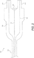
- Connector 102 includes one or more of prongs 216 and 218, and may include, but is not limited to, connector cable 124, one or more electrical wires 104, one or more of illumination connectors 106 and 108, and/or an electrical connection 220.
- connector cable 124 may be connected to the distal end of connector 102.
- Connector cable 124 may be connected to the proximal end of endoscope 112.
- connector cable 124 may be connected to handle 126 at the proximal end 176 of shaft 113.
- Electrical wires 104 and/or illumination connectors 106 and 108 may be disposed within and/or extend the length of connector cable 124.
- Electrical wires 104 and/or illumination connectors 106 and 108 may extend the length of connector 102.
- the length of connector cable 124 may be less than approximately 4.6 meters. It is contemplated that connector 102 may be the only connector for electrical and illumination connections between endoscope 112 and control unit 114.
- Electric wires 104 may extend to electrical connection 220.
- electrical connection 220 may be placed in electric communication with electrical interface 120, illustrated in FIG. 1 .
- electrical connection 220 may include one or more contacts or pads (not shown) that may be removably coupled to one or more contacts or pins (not shown) of electrical interface 120.
- electrical wires 104 may extend along a longitudinal axis of connector 102.
- electrical wires 104 may be located between illumination connectors 106 and 108. This may aid in correctly aligning illumination connectors 106 and 108 to light sources 116 and 118, which may be spaced apart within control unit 114. Separating light sources 116 and 118 may be desired for a variety of reasons including, for example, accommodating the sizes of the light sources 116 and 118, avoiding the possibility of crossing light paths of light sources 116 and 118, and/or helping to disperse heat radiating from the light sources 116 and 118.
- Illumination connectors 106 and 108 may extend through prongs 216 and 218, respectively.
- Prongs 216 and 218 may connect to control unit 114.
- Prongs 216 and 218 may be sized to be received by control unit 114.
- prongs 216 and 218 may be approximately 5 cm to 10 cm long.
- Light sources 116 and 118 may be approximately 1.25 cm to 4 cm apart.
- prongs 216 and 218 may be configured so that illumination connectors 106 and 108 are aligned with the light sources 116 and 118 (e.g., prongs 216 and 218 may be approximately 1.25 cm to 4 cm apart).
- illumination connectors 106 and 108, and prongs 216 and 218, may also be approximately 2.5 cm apart at the location where they are received by control unit 114.
- the tolerances for aligning an illumination connector with a light source may be between approximately 0.10 mm and approximately 1.0 mm or preferably approximately 0.25 mm. The tolerances may depend on the amount of light required. For example, the less light necessary to adequately illuminate the desired area, the larger the tolerances.
- prongs 216 and 218 are shown in FIG. 2 , it should be understood that a more than two prongs may be present on connector 102. More than two prongs may be used in an example where endoscope 112 includes more than two light sources and more than two illumination connectors. In some examples, a prong may contain more than one illumination connector. Prong 216 and/or prong 218 may assist with aligning electrical connector 220 with electrical interface 120, when connector 120 is attached to control unit 114.
- FIG. 3 An exemplary port or socket 330 is illustrated in FIG. 3 .
- Socket 130 of FIG. 1 may be similar to socket 330.
- Socket 330 includes illumination connector openings 326 and 328, and may include, but is not limited to, fastener openings 332, and/or electrical interface 120.
- socket 330 may be attached to a side surface of control unit 114.
- Socket 330 may be attached to or contained within control unit 114 by inserting fasteners through fastener holes 332.
- socket 330 may be attached by inserting screws through fastener holes 332.
- Connector openings 326 and 328 are configured to receive prongs 216 and 218, respectively.
- Connector openings 326 and 328 and prongs 216 and 218 may have a friction fit to help maintain coupling. In some examples, friction fit may also be achieved between other elements of socket 330 and connector 102.
- Connector openings 326 and 328 may allow illumination connectors 106 and 108, in prongs 216 and 218, to access control unit 114 and align with light sources 116 and 118 of FIG. 1 .
- prongs 216 and 218 may bring illumination connectors 106 and 108 into contact with light sources 116 and 118, such that light may be transmitted from light sources 116 and 118 into illumination connectors 106 and 108. It is contemplated that prongs 216 and 218 of connector 102 may be fully seated in connector openings 326 and 328, thereby coupling illumination connectors 106 and 108 to light sources 116 and 118, at the same time that electrical connection 220 is fully seated on, in, or against electrical interface 120 at socket 330.
- FIG. 4 illustrates an example of socket 330 connected to connector 102.
- Connector cable 124 may connect connector 102 to another device, such as endoscope 112.
- connector cable 124 may connect connector 102 to handle 126 of endoscope 112.
Landscapes
- Health & Medical Sciences (AREA)
- Life Sciences & Earth Sciences (AREA)
- Surgery (AREA)
- Engineering & Computer Science (AREA)
- Physics & Mathematics (AREA)
- Optics & Photonics (AREA)
- Biomedical Technology (AREA)
- General Health & Medical Sciences (AREA)
- Pathology (AREA)
- Nuclear Medicine, Radiotherapy & Molecular Imaging (AREA)
- Biophysics (AREA)
- Heart & Thoracic Surgery (AREA)
- Medical Informatics (AREA)
- Molecular Biology (AREA)
- Animal Behavior & Ethology (AREA)
- Radiology & Medical Imaging (AREA)
- Public Health (AREA)
- Veterinary Medicine (AREA)
- Signal Processing (AREA)
- Microelectronics & Electronic Packaging (AREA)
- Manufacturing & Machinery (AREA)
- Endoscopes (AREA)
- Instruments For Viewing The Inside Of Hollow Bodies (AREA)
Claims (12)
- Medizinische Vorrichtungsanordnung, aufweisend:eine medizinische Vorrichtung, aufweisend:eine Bildgebungsvorrichtung (110),eine mit der Bildgebungsvorrichtung gekoppelte elektrische Leitung (104),eine erste Beleuchtungsvorrichtung (168),eine zweite Beleuchtungsvorrichtung (168),einen ersten Beleuchtungsverbinder (106), der mit der ersten Beleuchtungsvorrichtung gekoppelt ist,einen zweiten Beleuchtungsverbinder (108), der mit der zweiten Beleuchtungsvorrichtung gekoppelt ist,einen Verbinder (102), der einen ersten Stift (216) und einen zweiten Stift (218) aufweist, wobei der Verbinder mit der elektrischen Leitung und dem ersten und zweiten Beleuchtungsverbinder (106, 108) gekoppelt ist, wobei sich der erste Beleuchtungsverbinder durch den ersten Stift und der zweite Beleuchtungsverbinder durch den zweiten Stift erstreckt; undeine Steuereinheit (114), aufweisend:eine elektrische Schnittstelle (120),eine erste Lichtquelle (116, 118), die mindestens eine Leuchtdiode aufweist, die zum Übertragen von Licht in den ersten Beleuchtungsverbinder ausgebildet ist,eine zweite Lichtquelle (118), die zum Übertragen von Licht in den zweiten Beleuchtungsverbinder ausgebildet ist, undeinen Anschluss (130), der Beleuchtungsverbinderöffnungen (326, 328) aufweist, die zum Aufnehmen des ersten und zweiten Stifts (216, 218) des Verbinders (102) ausgebildet sind, um die elektrische Leitung operativ mit der elektrischen Schnittstelle zu koppeln, den ersten Beleuchtungsverbinder operativ mit der ersten Lichtquelle zu koppeln und den zweiten Beleuchtungsverbinder operativ mit der zweiten Lichtquelle zu koppeln, wobei der Verbinder lösbar am Anschluss anbringbar ist.
- Medizinische Vorrichtungsanordnung nach Anspruch 1, wobei der erste und/oder der zweite Beleuchtungsverbinder mindestens eine Lichtleitfaser aufweist, die zum Übertragen von Licht durch die medizinische Vorrichtung ausgebildet ist.
- Medizinische Vorrichtungsanordnung nach einem der vorstehenden Ansprüche, wobei die Steuereinheit eine mit der elektrischen Schnittstelle gekoppelte Verarbeitungseinheit aufweist, wobei die Verarbeitungseinheit zum Empfangen von Bildgebungsdaten von der Bildgebungsvorrichtung durch die elektrische Leitung und die elektrische Schnittstelle ausgebildet ist.
- Medizinische Vorrichtungsanordnung nach Anspruch 3, wobei der Verbinder ein einziges Kabel aufweist, die elektrische Leitung und der erste und zweite Beleuchtungsverbinder mindestens teilweise in dem Kabel aufgenommen sind und die Steuereinheit ein einziges Gehäuse aufweist, das die elektrische Schnittstelle, die Lichtquellen und die Verarbeitungseinheit enthält.
- Medizinische Vorrichtungsanordnung nach einem der vorstehenden Ansprüche, wobei die medizinische Vorrichtung ein Endoskop ist.
- Medizinische Vorrichtungsanordnung nach einem der vorstehenden Ansprüche, wobei sich die Bildgebungsvorrichtung an einem distalen Ende des Endoskops befindet.
- Verfahren zum Verbinden der medizinischen Vorrichtung der medizinischen Anordnung von Anspruch 1 mit der Steuereinheit der medizinischen Anordnung von Anspruch 1, aufweisend:
Koppeln des Verbinders an der medizinischen Vorrichtung mit dem Anschluss an der Steuereinheit, wobei der Verbinder lösbar am Anschluss anbringbar ist, wobei das Koppeln des Verbinders mit dem Anschluss aufweist:operatives Koppeln eines ersten Beleuchtungsverbinders im Verbinder mit der ersten Lichtquelle in der Steuereinheit, wobei die erste Lichtquelle die Leuchtdiode aufweist, die das Übertragen von Licht von der ersten Lichtquelle in den ersten Beleuchtungsverbinder und vom ersten Beleuchtungsverbinder zur ersten Beleuchtungsvorrichtung in der medizinischen Vorrichtung gestattet,operatives Koppeln eines zweiten Beleuchtungsverbinders im Verbinder mit der zweiten Lichtquelle in der Steuereinheit, was das Übertragen von Licht von der zweiten Lichtquelle in den zweiten Beleuchtungsverbinder und vom zweiten Beleuchtungsverbinder zur zweiten Beleuchtungsvorrichtung in der medizinischen Vorrichtung gestattet,operatives Koppeln der elektrischen Leitung im Verbinder mit der elektrischen Schnittstelle in der Steuereinheit, was das Fließen von elektrischem Strom von der elektrischen Schnittstelle zur Bildgebungsvorrichtung in der medizinischen Vorrichtung und das Fließen von Bildgebungsdaten von der Bildgebungsvorrichtung zur elektrischen Schnittstelle gestattet. - Verfahren nach Anspruch 7, wobei die Beleuchtungsverbinder und die Lichtquellen gleichzeitig mit dem operativen Koppeln der elektrischen Leitung und der elektrischen Schnittstelle operativ gekoppelt werden.
- Verfahren nach einem der vorstehenden Ansprüche, wobei der Verbinder fest an einem Griff der medizinischen Vorrichtung angebracht ist.
- Verfahren nach einem der vorstehenden Ansprüche, wobei das operative Koppeln der Beleuchtungsverbinder mit den Lichtquellen das operative Koppeln mehrerer Beleuchtungsverbinder im Verbinder mit einer oder mehreren Lichtquellen aufweist.
- Verfahren nach einem der vorstehenden Ansprüche, wobei die medizinische Vorrichtung ein Endoskop ist.
- Medizinische Vorrichtungsanordnung nach einem der Ansprüche 1 bis 7, wobei die medizinische Vorrichtung ein Endoskop ist, aufweisend:einen länglichen Schaft mit einem proximalen und einem distalen Ende,eine Bildgebungsvorrichtung am distalen Ende des länglichen Schafts, wobei sich die elektrische Leitung durch den länglichen Schaft erstreckt,eine erste und zweite Beleuchtungsvorrichtung am distalen Ende des länglichen Schafts,den ersten und zweiten Beleuchtungsverbinder, die sich von einem distalen Ende des Endoskops zu einem proximalen Ende des Verbinders durch den länglichen Schaft erstrecken, undeinen Verbinder, der mindestens einen Teil der elektrischen Leitung und mindestens einen Teil des ersten und zweiten Beleuchtungsverbinders aufnimmt.
Priority Applications (1)
| Application Number | Priority Date | Filing Date | Title |
|---|---|---|---|
| EP21183866.9A EP3928681A1 (de) | 2014-12-29 | 2015-12-22 | Anordnung einer medizinischen vorrichtungen |
Applications Claiming Priority (2)
| Application Number | Priority Date | Filing Date | Title |
|---|---|---|---|
| US201462097438P | 2014-12-29 | 2014-12-29 | |
| PCT/US2015/067419 WO2016109349A1 (en) | 2014-12-29 | 2015-12-22 | Medical device assembly and related methods |
Related Child Applications (1)
| Application Number | Title | Priority Date | Filing Date |
|---|---|---|---|
| EP21183866.9A Division EP3928681A1 (de) | 2014-12-29 | 2015-12-22 | Anordnung einer medizinischen vorrichtungen |
Publications (2)
| Publication Number | Publication Date |
|---|---|
| EP3220799A1 EP3220799A1 (de) | 2017-09-27 |
| EP3220799B1 true EP3220799B1 (de) | 2021-07-07 |
Family
ID=55273521
Family Applications (2)
| Application Number | Title | Priority Date | Filing Date |
|---|---|---|---|
| EP15831025.0A Active EP3220799B1 (de) | 2014-12-29 | 2015-12-22 | Anordnung einer medizinischen vorrichtung und zugehörige verfahren |
| EP21183866.9A Pending EP3928681A1 (de) | 2014-12-29 | 2015-12-22 | Anordnung einer medizinischen vorrichtungen |
Family Applications After (1)
| Application Number | Title | Priority Date | Filing Date |
|---|---|---|---|
| EP21183866.9A Pending EP3928681A1 (de) | 2014-12-29 | 2015-12-22 | Anordnung einer medizinischen vorrichtungen |
Country Status (6)
| Country | Link |
|---|---|
| US (5) | US10463234B2 (de) |
| EP (2) | EP3220799B1 (de) |
| JP (1) | JP6695881B2 (de) |
| CN (1) | CN107278135B (de) |
| AU (1) | AU2015374329B2 (de) |
| WO (1) | WO2016109349A1 (de) |
Families Citing this family (12)
| Publication number | Priority date | Publication date | Assignee | Title |
|---|---|---|---|---|
| EP4321081A3 (de) * | 2016-06-21 | 2024-04-24 | EndoChoice, Inc. | Endoskopsystem mit mehreren verbindungsschnittstellen zur schnittstelle mit verschiedenen videodatensignalquellen |
| WO2018089770A1 (en) * | 2016-11-11 | 2018-05-17 | Boston Scientific Scimed, Inc. | Disposable medical systems, devices, and related methods |
| AU2017387098B2 (en) * | 2016-12-27 | 2022-12-15 | DePuy Synthes Products, Inc. | Systems, methods, and devices for providing illumination in an endoscopic imaging environment |
| CN110785112B (zh) * | 2017-06-28 | 2022-06-03 | 奥林巴斯株式会社 | 光源系统、内窥镜系统和光源控制方法 |
| EP3943997B1 (de) * | 2019-03-19 | 2025-04-23 | Sony Olympus Medical Solutions Inc. | Medizinisches steuergerät und medizinisches beobachtungsgerät |
| WO2020250393A1 (ja) | 2019-06-13 | 2020-12-17 | オリンパス株式会社 | プラグ、コネクタおよび内視鏡装置 |
| US11589819B2 (en) | 2019-06-20 | 2023-02-28 | Cilag Gmbh International | Offset illumination of a scene using multiple emitters in a laser mapping imaging system |
| US11550057B2 (en) * | 2019-06-20 | 2023-01-10 | Cilag Gmbh International | Offset illumination of a scene using multiple emitters in a fluorescence imaging system |
| US11931009B2 (en) | 2019-06-20 | 2024-03-19 | Cilag Gmbh International | Offset illumination of a scene using multiple emitters in a hyperspectral imaging system |
| US11903563B2 (en) | 2019-06-20 | 2024-02-20 | Cilag Gmbh International | Offset illumination of a scene using multiple emitters in a fluorescence imaging system |
| WO2022067300A1 (en) * | 2020-09-25 | 2022-03-31 | Boston Scientific Scimed, Inc. | Connected medical devices |
| US20240268649A1 (en) * | 2023-02-09 | 2024-08-15 | Cilag Gmbh International | Integrated cable connector for luminous efficiency |
Citations (2)
| Publication number | Priority date | Publication date | Assignee | Title |
|---|---|---|---|---|
| US20070093688A1 (en) * | 2005-10-26 | 2007-04-26 | Pentax Corporation | Light source apparatus for endoscope |
| US20110208004A1 (en) * | 2008-11-18 | 2011-08-25 | Benjamin Hyman Feingold | Endoscopic led light source having a feedback control system |
Family Cites Families (31)
| Publication number | Priority date | Publication date | Assignee | Title |
|---|---|---|---|---|
| US4754328A (en) * | 1984-01-03 | 1988-06-28 | Medical Dynamics, Inc. | Laser endoscope |
| US4862258A (en) * | 1987-05-13 | 1989-08-29 | Olympus Optical Co., Ltd. | Multiple characteristic endoscope light source for frame sequential color imaging, mosaic color imaging and fiber image guide scopes |
| US5717806A (en) * | 1994-12-28 | 1998-02-10 | Welch Allyn, Inc. | Bifurcated randomized fiber bundle light cable for directing light from multiple light sources to single light output |
| JP3615890B2 (ja) * | 1996-12-04 | 2005-02-02 | フジノン株式会社 | 電子内視鏡装置 |
| US20060115473A1 (en) * | 2000-12-14 | 2006-06-01 | Biogen Idec Ma Inc., A Massachusetts Corporation | Methods of treating central nervous system ischemic or hemorrhagic injury using anti alpha4 integrin antagonists |
| JP3842941B2 (ja) * | 2000-01-14 | 2006-11-08 | ペンタックス株式会社 | 電子内視鏡 |
| JP2002112959A (ja) * | 2000-10-06 | 2002-04-16 | Asahi Optical Co Ltd | 電子内視鏡の照明装置 |
| JP3706326B2 (ja) * | 2001-10-17 | 2005-10-12 | オリンパス株式会社 | 内視鏡装置 |
| US6960161B2 (en) * | 2001-12-28 | 2005-11-01 | Karl Storz Imaging Inc. | Unified electrical and illumination cable for endoscopic video imaging system |
| US7520853B2 (en) | 2001-12-28 | 2009-04-21 | Karl Storz Imaging, Inc. | Updateable endoscopic video imaging system |
| US7578786B2 (en) * | 2003-04-01 | 2009-08-25 | Boston Scientific Scimed, Inc. | Video endoscope |
| US20040199052A1 (en) | 2003-04-01 | 2004-10-07 | Scimed Life Systems, Inc. | Endoscopic imaging system |
| US8118732B2 (en) | 2003-04-01 | 2012-02-21 | Boston Scientific Scimed, Inc. | Force feedback control system for video endoscope |
| JP4420638B2 (ja) | 2003-09-08 | 2010-02-24 | Hoya株式会社 | 内視鏡 |
| WO2005077249A1 (ja) * | 2004-02-16 | 2005-08-25 | Olympus Corporation | 内視鏡システム |
| JP2005279253A (ja) * | 2004-03-02 | 2005-10-13 | Olympus Corp | 内視鏡 |
| JP2008048905A (ja) * | 2006-08-24 | 2008-03-06 | Olympus Medical Systems Corp | 内視鏡装置 |
| JP5009190B2 (ja) * | 2008-02-27 | 2012-08-22 | オリンパスメディカルシステムズ株式会社 | 電気コネクタ |
| JP5178239B2 (ja) * | 2008-02-27 | 2013-04-10 | オリンパスメディカルシステムズ株式会社 | 医療用システム |
| US7758369B2 (en) * | 2008-04-25 | 2010-07-20 | Tyco Electronics Corporation | Plug connector for use with a receptacle |
| DE102008033506A1 (de) * | 2008-07-07 | 2010-01-14 | Karl Storz Gmbh & Co. Kg | Videoendoskop mit schaltbaren Halbleiterlichtquellen |
| JP5271091B2 (ja) * | 2009-01-09 | 2013-08-21 | 日本コヴィディエン株式会社 | 内視鏡の接続構造 |
| JP5277187B2 (ja) * | 2010-01-28 | 2013-08-28 | 富士フイルム株式会社 | 医療機器及び内視鏡装置 |
| WO2011114957A1 (ja) | 2010-03-16 | 2011-09-22 | オリンパスメディカルシステムズ株式会社 | コネクタシステム |
| WO2012021212A1 (en) | 2010-08-10 | 2012-02-16 | Boston Scientific Scimed, Inc. | Endoscopic system for enhanced visualization |
| US8702594B2 (en) * | 2010-10-21 | 2014-04-22 | Avram Allan Edidin | Imaging system having a quick connect coupling interface |
| JP2013099464A (ja) * | 2011-11-09 | 2013-05-23 | Fujifilm Corp | 内視鏡システム、内視鏡システムのプロセッサ装置、及び画像表示方法 |
| CA2798716A1 (en) * | 2011-12-13 | 2013-06-13 | Endochoice Innovation Center Ltd. | Removable tip endoscope |
| JP5851856B2 (ja) * | 2012-01-19 | 2016-02-03 | オリンパス株式会社 | 光源システム |
| JP2014113350A (ja) | 2012-12-11 | 2014-06-26 | Panasonic Corp | 内視鏡および内視鏡システム |
| US9331444B2 (en) * | 2014-02-24 | 2016-05-03 | National Products, Inc. | Docking sleeve with electrical adapter |
-
2015
- 2015-12-22 CN CN201580077054.0A patent/CN107278135B/zh active Active
- 2015-12-22 WO PCT/US2015/067419 patent/WO2016109349A1/en not_active Ceased
- 2015-12-22 US US14/978,638 patent/US10463234B2/en active Active
- 2015-12-22 JP JP2017533382A patent/JP6695881B2/ja active Active
- 2015-12-22 EP EP15831025.0A patent/EP3220799B1/de active Active
- 2015-12-22 EP EP21183866.9A patent/EP3928681A1/de active Pending
- 2015-12-22 AU AU2015374329A patent/AU2015374329B2/en active Active
-
2019
- 2019-09-16 US US16/571,327 patent/US11241143B2/en active Active
-
2021
- 2021-12-27 US US17/562,232 patent/US11737652B2/en active Active
-
2023
- 2023-07-14 US US18/352,486 patent/US12329355B2/en active Active
-
2025
- 2025-01-16 US US19/025,210 patent/US20250151982A1/en active Pending
Patent Citations (2)
| Publication number | Priority date | Publication date | Assignee | Title |
|---|---|---|---|---|
| US20070093688A1 (en) * | 2005-10-26 | 2007-04-26 | Pentax Corporation | Light source apparatus for endoscope |
| US20110208004A1 (en) * | 2008-11-18 | 2011-08-25 | Benjamin Hyman Feingold | Endoscopic led light source having a feedback control system |
Also Published As
| Publication number | Publication date |
|---|---|
| US11737652B2 (en) | 2023-08-29 |
| US10463234B2 (en) | 2019-11-05 |
| US20250151982A1 (en) | 2025-05-15 |
| CN107278135A (zh) | 2017-10-20 |
| AU2015374329B2 (en) | 2020-10-01 |
| US20200008656A1 (en) | 2020-01-09 |
| CA2971290A1 (en) | 2016-07-07 |
| US11241143B2 (en) | 2022-02-08 |
| US20160183771A1 (en) | 2016-06-30 |
| AU2015374329A1 (en) | 2017-07-13 |
| EP3220799A1 (de) | 2017-09-27 |
| JP2018500995A (ja) | 2018-01-18 |
| US12329355B2 (en) | 2025-06-17 |
| JP6695881B2 (ja) | 2020-05-20 |
| CN107278135B (zh) | 2020-02-14 |
| WO2016109349A1 (en) | 2016-07-07 |
| US20230355080A1 (en) | 2023-11-09 |
| EP3928681A1 (de) | 2021-12-29 |
| US20220117469A1 (en) | 2022-04-21 |
Similar Documents
| Publication | Publication Date | Title |
|---|---|---|
| US11737652B2 (en) | Medical device assembly and related methods | |
| US6960161B2 (en) | Unified electrical and illumination cable for endoscopic video imaging system | |
| CN111035347A (zh) | 用于内窥镜的铰接式尖端部分 | |
| US20160000301A1 (en) | Borescopes and related methods and systems | |
| JP7143492B2 (ja) | 伝送ケーブル | |
| WO2003022135A2 (en) | Endoscopic system with a solid-state light source | |
| JP2001061777A (ja) | 電子内視鏡 | |
| CA2971290C (en) | Medical device assembly and related methods | |
| US12303108B2 (en) | Endoscope, distal end portion of endoscope, and insertion portion of endoscope | |
| US11026562B2 (en) | Endoscope | |
| JP4388452B2 (ja) | 電子内視鏡 | |
| JP6328988B2 (ja) | 超音波内視鏡システム | |
| US20250194902A1 (en) | Relay adapter and medical apparatus system | |
| JP2020500617A (ja) | 携帯型内視鏡 | |
| US20160077323A1 (en) | Endoscope | |
| JP2020188959A (ja) | 内視鏡システムおよび内視鏡装置 |
Legal Events
| Date | Code | Title | Description |
|---|---|---|---|
| STAA | Information on the status of an ep patent application or granted ep patent |
Free format text: STATUS: THE INTERNATIONAL PUBLICATION HAS BEEN MADE |
|
| PUAI | Public reference made under article 153(3) epc to a published international application that has entered the european phase |
Free format text: ORIGINAL CODE: 0009012 |
|
| STAA | Information on the status of an ep patent application or granted ep patent |
Free format text: STATUS: REQUEST FOR EXAMINATION WAS MADE |
|
| 17P | Request for examination filed |
Effective date: 20170621 |
|
| AK | Designated contracting states |
Kind code of ref document: A1 Designated state(s): AL AT BE BG CH CY CZ DE DK EE ES FI FR GB GR HR HU IE IS IT LI LT LU LV MC MK MT NL NO PL PT RO RS SE SI SK SM TR |
|
| AX | Request for extension of the european patent |
Extension state: BA ME |
|
| DAV | Request for validation of the european patent (deleted) | ||
| DAX | Request for extension of the european patent (deleted) | ||
| STAA | Information on the status of an ep patent application or granted ep patent |
Free format text: STATUS: EXAMINATION IS IN PROGRESS |
|
| 17Q | First examination report despatched |
Effective date: 20190128 |
|
| GRAP | Despatch of communication of intention to grant a patent |
Free format text: ORIGINAL CODE: EPIDOSNIGR1 |
|
| STAA | Information on the status of an ep patent application or granted ep patent |
Free format text: STATUS: GRANT OF PATENT IS INTENDED |
|
| INTG | Intention to grant announced |
Effective date: 20210211 |
|
| GRAS | Grant fee paid |
Free format text: ORIGINAL CODE: EPIDOSNIGR3 |
|
| GRAA | (expected) grant |
Free format text: ORIGINAL CODE: 0009210 |
|
| STAA | Information on the status of an ep patent application or granted ep patent |
Free format text: STATUS: THE PATENT HAS BEEN GRANTED |
|
| AK | Designated contracting states |
Kind code of ref document: B1 Designated state(s): AL AT BE BG CH CY CZ DE DK EE ES FI FR GB GR HR HU IE IS IT LI LT LU LV MC MK MT NL NO PL PT RO RS SE SI SK SM TR |
|
| REG | Reference to a national code |
Ref country code: GB Ref legal event code: FG4D |
|
| REG | Reference to a national code |
Ref country code: AT Ref legal event code: REF Ref document number: 1407743 Country of ref document: AT Kind code of ref document: T Effective date: 20210715 |
|
| REG | Reference to a national code |
Ref country code: DE Ref legal event code: R096 Ref document number: 602015071157 Country of ref document: DE |
|
| REG | Reference to a national code |
Ref country code: IE Ref legal event code: FG4D |
|
| REG | Reference to a national code |
Ref country code: NL Ref legal event code: FP |
|
| REG | Reference to a national code |
Ref country code: LT Ref legal event code: MG9D |
|
| REG | Reference to a national code |
Ref country code: AT Ref legal event code: MK05 Ref document number: 1407743 Country of ref document: AT Kind code of ref document: T Effective date: 20210707 |
|
| PG25 | Lapsed in a contracting state [announced via postgrant information from national office to epo] |
Ref country code: BG Free format text: LAPSE BECAUSE OF FAILURE TO SUBMIT A TRANSLATION OF THE DESCRIPTION OR TO PAY THE FEE WITHIN THE PRESCRIBED TIME-LIMIT Effective date: 20211007 Ref country code: AT Free format text: LAPSE BECAUSE OF FAILURE TO SUBMIT A TRANSLATION OF THE DESCRIPTION OR TO PAY THE FEE WITHIN THE PRESCRIBED TIME-LIMIT Effective date: 20210707 Ref country code: LT Free format text: LAPSE BECAUSE OF FAILURE TO SUBMIT A TRANSLATION OF THE DESCRIPTION OR TO PAY THE FEE WITHIN THE PRESCRIBED TIME-LIMIT Effective date: 20210707 Ref country code: NO Free format text: LAPSE BECAUSE OF FAILURE TO SUBMIT A TRANSLATION OF THE DESCRIPTION OR TO PAY THE FEE WITHIN THE PRESCRIBED TIME-LIMIT Effective date: 20211007 Ref country code: PT Free format text: LAPSE BECAUSE OF FAILURE TO SUBMIT A TRANSLATION OF THE DESCRIPTION OR TO PAY THE FEE WITHIN THE PRESCRIBED TIME-LIMIT Effective date: 20211108 Ref country code: ES Free format text: LAPSE BECAUSE OF FAILURE TO SUBMIT A TRANSLATION OF THE DESCRIPTION OR TO PAY THE FEE WITHIN THE PRESCRIBED TIME-LIMIT Effective date: 20210707 Ref country code: FI Free format text: LAPSE BECAUSE OF FAILURE TO SUBMIT A TRANSLATION OF THE DESCRIPTION OR TO PAY THE FEE WITHIN THE PRESCRIBED TIME-LIMIT Effective date: 20210707 Ref country code: HR Free format text: LAPSE BECAUSE OF FAILURE TO SUBMIT A TRANSLATION OF THE DESCRIPTION OR TO PAY THE FEE WITHIN THE PRESCRIBED TIME-LIMIT Effective date: 20210707 Ref country code: SE Free format text: LAPSE BECAUSE OF FAILURE TO SUBMIT A TRANSLATION OF THE DESCRIPTION OR TO PAY THE FEE WITHIN THE PRESCRIBED TIME-LIMIT Effective date: 20210707 Ref country code: RS Free format text: LAPSE BECAUSE OF FAILURE TO SUBMIT A TRANSLATION OF THE DESCRIPTION OR TO PAY THE FEE WITHIN THE PRESCRIBED TIME-LIMIT Effective date: 20210707 |
|
| PG25 | Lapsed in a contracting state [announced via postgrant information from national office to epo] |
Ref country code: PL Free format text: LAPSE BECAUSE OF FAILURE TO SUBMIT A TRANSLATION OF THE DESCRIPTION OR TO PAY THE FEE WITHIN THE PRESCRIBED TIME-LIMIT Effective date: 20210707 Ref country code: LV Free format text: LAPSE BECAUSE OF FAILURE TO SUBMIT A TRANSLATION OF THE DESCRIPTION OR TO PAY THE FEE WITHIN THE PRESCRIBED TIME-LIMIT Effective date: 20210707 Ref country code: GR Free format text: LAPSE BECAUSE OF FAILURE TO SUBMIT A TRANSLATION OF THE DESCRIPTION OR TO PAY THE FEE WITHIN THE PRESCRIBED TIME-LIMIT Effective date: 20211008 |
|
| REG | Reference to a national code |
Ref country code: DE Ref legal event code: R097 Ref document number: 602015071157 Country of ref document: DE |
|
| PG25 | Lapsed in a contracting state [announced via postgrant information from national office to epo] |
Ref country code: DK Free format text: LAPSE BECAUSE OF FAILURE TO SUBMIT A TRANSLATION OF THE DESCRIPTION OR TO PAY THE FEE WITHIN THE PRESCRIBED TIME-LIMIT Effective date: 20210707 |
|
| PLBE | No opposition filed within time limit |
Free format text: ORIGINAL CODE: 0009261 |
|
| STAA | Information on the status of an ep patent application or granted ep patent |
Free format text: STATUS: NO OPPOSITION FILED WITHIN TIME LIMIT |
|
| PG25 | Lapsed in a contracting state [announced via postgrant information from national office to epo] |
Ref country code: SM Free format text: LAPSE BECAUSE OF FAILURE TO SUBMIT A TRANSLATION OF THE DESCRIPTION OR TO PAY THE FEE WITHIN THE PRESCRIBED TIME-LIMIT Effective date: 20210707 Ref country code: SK Free format text: LAPSE BECAUSE OF FAILURE TO SUBMIT A TRANSLATION OF THE DESCRIPTION OR TO PAY THE FEE WITHIN THE PRESCRIBED TIME-LIMIT Effective date: 20210707 Ref country code: RO Free format text: LAPSE BECAUSE OF FAILURE TO SUBMIT A TRANSLATION OF THE DESCRIPTION OR TO PAY THE FEE WITHIN THE PRESCRIBED TIME-LIMIT Effective date: 20210707 Ref country code: EE Free format text: LAPSE BECAUSE OF FAILURE TO SUBMIT A TRANSLATION OF THE DESCRIPTION OR TO PAY THE FEE WITHIN THE PRESCRIBED TIME-LIMIT Effective date: 20210707 Ref country code: CZ Free format text: LAPSE BECAUSE OF FAILURE TO SUBMIT A TRANSLATION OF THE DESCRIPTION OR TO PAY THE FEE WITHIN THE PRESCRIBED TIME-LIMIT Effective date: 20210707 Ref country code: AL Free format text: LAPSE BECAUSE OF FAILURE TO SUBMIT A TRANSLATION OF THE DESCRIPTION OR TO PAY THE FEE WITHIN THE PRESCRIBED TIME-LIMIT Effective date: 20210707 |
|
| 26N | No opposition filed |
Effective date: 20220408 |
|
| PG25 | Lapsed in a contracting state [announced via postgrant information from national office to epo] |
Ref country code: MC Free format text: LAPSE BECAUSE OF FAILURE TO SUBMIT A TRANSLATION OF THE DESCRIPTION OR TO PAY THE FEE WITHIN THE PRESCRIBED TIME-LIMIT Effective date: 20210707 Ref country code: IT Free format text: LAPSE BECAUSE OF FAILURE TO SUBMIT A TRANSLATION OF THE DESCRIPTION OR TO PAY THE FEE WITHIN THE PRESCRIBED TIME-LIMIT Effective date: 20210707 |
|
| REG | Reference to a national code |
Ref country code: CH Ref legal event code: PL |
|
| REG | Reference to a national code |
Ref country code: BE Ref legal event code: MM Effective date: 20211231 |
|
| PG25 | Lapsed in a contracting state [announced via postgrant information from national office to epo] |
Ref country code: LU Free format text: LAPSE BECAUSE OF NON-PAYMENT OF DUE FEES Effective date: 20211222 |
|
| PG25 | Lapsed in a contracting state [announced via postgrant information from national office to epo] |
Ref country code: FR Free format text: LAPSE BECAUSE OF NON-PAYMENT OF DUE FEES Effective date: 20211231 Ref country code: BE Free format text: LAPSE BECAUSE OF NON-PAYMENT OF DUE FEES Effective date: 20211231 |
|
| PG25 | Lapsed in a contracting state [announced via postgrant information from national office to epo] |
Ref country code: LI Free format text: LAPSE BECAUSE OF NON-PAYMENT OF DUE FEES Effective date: 20211231 Ref country code: CH Free format text: LAPSE BECAUSE OF NON-PAYMENT OF DUE FEES Effective date: 20211231 |
|
| PG25 | Lapsed in a contracting state [announced via postgrant information from national office to epo] |
Ref country code: HU Free format text: LAPSE BECAUSE OF FAILURE TO SUBMIT A TRANSLATION OF THE DESCRIPTION OR TO PAY THE FEE WITHIN THE PRESCRIBED TIME-LIMIT; INVALID AB INITIO Effective date: 20151222 |
|
| PG25 | Lapsed in a contracting state [announced via postgrant information from national office to epo] |
Ref country code: CY Free format text: LAPSE BECAUSE OF FAILURE TO SUBMIT A TRANSLATION OF THE DESCRIPTION OR TO PAY THE FEE WITHIN THE PRESCRIBED TIME-LIMIT Effective date: 20210707 |
|
| PG25 | Lapsed in a contracting state [announced via postgrant information from national office to epo] |
Ref country code: MK Free format text: LAPSE BECAUSE OF FAILURE TO SUBMIT A TRANSLATION OF THE DESCRIPTION OR TO PAY THE FEE WITHIN THE PRESCRIBED TIME-LIMIT Effective date: 20210707 |
|
| PG25 | Lapsed in a contracting state [announced via postgrant information from national office to epo] |
Ref country code: TR Free format text: LAPSE BECAUSE OF FAILURE TO SUBMIT A TRANSLATION OF THE DESCRIPTION OR TO PAY THE FEE WITHIN THE PRESCRIBED TIME-LIMIT Effective date: 20210707 |
|
| PG25 | Lapsed in a contracting state [announced via postgrant information from national office to epo] |
Ref country code: MT Free format text: LAPSE BECAUSE OF FAILURE TO SUBMIT A TRANSLATION OF THE DESCRIPTION OR TO PAY THE FEE WITHIN THE PRESCRIBED TIME-LIMIT Effective date: 20210707 |
|
| PGFP | Annual fee paid to national office [announced via postgrant information from national office to epo] |
Ref country code: NL Payment date: 20251119 Year of fee payment: 11 |
|
| PGFP | Annual fee paid to national office [announced via postgrant information from national office to epo] |
Ref country code: DE Payment date: 20251126 Year of fee payment: 11 |
|
| PGFP | Annual fee paid to national office [announced via postgrant information from national office to epo] |
Ref country code: GB Payment date: 20251119 Year of fee payment: 11 |
|
| PGFP | Annual fee paid to national office [announced via postgrant information from national office to epo] |
Ref country code: IE Payment date: 20251121 Year of fee payment: 11 |