EP3221055B1 - Destructeur de documents de valeur - Google Patents
Destructeur de documents de valeur Download PDFInfo
- Publication number
- EP3221055B1 EP3221055B1 EP15795115.3A EP15795115A EP3221055B1 EP 3221055 B1 EP3221055 B1 EP 3221055B1 EP 15795115 A EP15795115 A EP 15795115A EP 3221055 B1 EP3221055 B1 EP 3221055B1
- Authority
- EP
- European Patent Office
- Prior art keywords
- cutting device
- cutting
- elements
- stripper elements
- value documents
- Prior art date
- Legal status (The legal status is an assumption and is not a legal conclusion. Google has not performed a legal analysis and makes no representation as to the accuracy of the status listed.)
- Active
Links
Images


Classifications
-
- B—PERFORMING OPERATIONS; TRANSPORTING
- B02—CRUSHING, PULVERISING, OR DISINTEGRATING; PREPARATORY TREATMENT OF GRAIN FOR MILLING
- B02C—CRUSHING, PULVERISING, OR DISINTEGRATING IN GENERAL; MILLING GRAIN
- B02C18/00—Disintegrating by knives or other cutting or tearing members which chop material into fragments
- B02C18/0007—Disintegrating by knives or other cutting or tearing members which chop material into fragments specially adapted for disintegrating documents
-
- B—PERFORMING OPERATIONS; TRANSPORTING
- B02—CRUSHING, PULVERISING, OR DISINTEGRATING; PREPARATORY TREATMENT OF GRAIN FOR MILLING
- B02C—CRUSHING, PULVERISING, OR DISINTEGRATING IN GENERAL; MILLING GRAIN
- B02C18/00—Disintegrating by knives or other cutting or tearing members which chop material into fragments
- B02C18/06—Disintegrating by knives or other cutting or tearing members which chop material into fragments with rotating knives
-
- B—PERFORMING OPERATIONS; TRANSPORTING
- B02—CRUSHING, PULVERISING, OR DISINTEGRATING; PREPARATORY TREATMENT OF GRAIN FOR MILLING
- B02C—CRUSHING, PULVERISING, OR DISINTEGRATING IN GENERAL; MILLING GRAIN
- B02C18/00—Disintegrating by knives or other cutting or tearing members which chop material into fragments
- B02C18/06—Disintegrating by knives or other cutting or tearing members which chop material into fragments with rotating knives
- B02C18/16—Details
- B02C18/22—Feed or discharge means
- B02C18/2225—Feed means
- B02C18/2283—Feed means using rollers
-
- B—PERFORMING OPERATIONS; TRANSPORTING
- B02—CRUSHING, PULVERISING, OR DISINTEGRATING; PREPARATORY TREATMENT OF GRAIN FOR MILLING
- B02C—CRUSHING, PULVERISING, OR DISINTEGRATING IN GENERAL; MILLING GRAIN
- B02C18/00—Disintegrating by knives or other cutting or tearing members which chop material into fragments
- B02C18/0007—Disintegrating by knives or other cutting or tearing members which chop material into fragments specially adapted for disintegrating documents
- B02C2018/0069—Disintegrating by knives or other cutting or tearing members which chop material into fragments specially adapted for disintegrating documents with stripping devices
Definitions
- the invention relates to a device for shredding value documents, e.g. Banknotes, checks, tickets, vouchers etc.
- Value documents that are no longer fit for circulation are known to be sorted out and destroyed.
- used banknotes z. B. by commercial banks, transport companies, etc., checked by means of banknote processing machines and sorted by their fitness for circulation. Notes that are so heavily soiled or damaged that they should not be re-circulated are destroyed, e.g. shredded. Also, in the quality inspection of new banknotes immediately after their production faulty banknotes are sorted out and shredded.
- the shredding of banknotes is eg from the EP0565112 B1 known.
- Known shredding devices have two rotatably mounted cutting devices, which rotate in opposite directions, and engage with their cutting edges.
- the banknotes to be shredded are successively drawn one after the other between the two cutting devices and thereby cut by the cutting edges into small chips, which are torn along. These chips are removed by a scraper from the cutting edges and fall down or are sucked.
- Another shredding device comprising scraper is off WO2004014559 known.
- the shredding device is designed for shredding documents of value and has at least two counter-rotatable cylindrical cutting devices, which lie opposite one another with respect to a transport path of the value documents to be shredded.
- the value documents to be shredded are transported one after the other along their transport path between the two cutting devices in order to shred them.
- the two cutting devices each have a plurality of cutting edges, which mutually interlock at the facing front sides of the two cutting devices to cut the transported along the transport path value documents using the cutting edges in a variety of Werturgischnipsel.
- the cutting device has, for example, a multiplicity of cutting disks, which have a circular outer contour have, wherein the cutting edges of the cutting device lie on the outside of the cutting discs and extend along the circumference.
- the cutting devices are each assigned a scraper having a plurality of mutually parallel scraper elements, which are arranged so that the stripping between the cutting edges of the respective cutting device to remove the Werturgischnipsel of the cutting edges, in particular located between the cutting edges Werturgischnipsel.
- the shape of the stripping elements is selected such that the stripping elements do not engage between the cutting edges of the respective cutting device at the front side of the respective cutting device facing the transport path of the value documents, but in particular not at the rear side of the respective cutting device facing away from the transport path of the value documents between the cutting edges of the respective cutting device to grab. This ensures that - viewed in the direction of rotation - after the scraper enough space for non-stripped Wert collectionschnipsel is created, which are pulled between the scraper and the cutter.
- the side of the roller-shaped cutting device which faces the transport path of the value documents is designated as the front side of the respective cylindrical cutting device.
- the rear side of the roller-shaped cutting device is correspondingly that side of the cylindrical cutting device which is remote from the transport path of the value documents.
- the underside of the cutting device is the side of the cutting device at which the Wertzanipsel leave the cutter.
- the scraper surrounds the respective cutting device preferably only at the front and bottom of the cutting device, but not at the back of the cutting device.
- the lowest angular position of the respective cutting device is that azimuthal angular position of the cutting device (ie with respect to the axis of rotation of the cutting device), which, viewed along the direction of rotation of the cutting device, is 90 ° to the connecting line of the axes of the two cutting devices (ie the center of the underside of the cutter).
- the stripping elements are stationary, i. they are not moved relative to the cutter.
- the stripping elements are not mounted on the axis of the cutting device, but in an existing outside the cutter recording.
- the attachment in an existing outside of the cutting device recording is advantageous because the shredder device is thereby easier to disassemble into its components scraper and cutter, e.g. to remove stuck value document snippets.
- the stripping elements protrude from the outside between the cutting edges of the respective cutting device.
- the wiping elements overlap the outer contour in a (circular arc) section which extends over an azimuthal angle section of the cutting device.
- the overlapping angle section in which the stripping elements overlap with the outer contour of the respective cutting device, does not reach the document shredded documents until after the cutting process.
- the shape of the stripping elements is selected such that the overlapping angle section in which the stripping elements and the outer contour of the cutting device overlap extends over at most 50 °, preferably at most 40 °, particularly preferably at most 25 °.
- the arc length of the overlap area along the outer contour of the cutting device is preferably at most 40 mm, more preferably at most 20 mm.
- the fact that the overlapping angle section is so short is achieved that as little as possible Werturgischnipsel hang in the space between the stripping and the cutting device.
- the azimuthal position of the overlapping angle section (azimuthally, ie with respect to the axis of rotation of the cutting device), in which the stripping elements overlap with the outer contour of the respective cutting device, is in an angular range between 20 ° and 100 °, viewed along the direction of rotation of the cutting device. in particular between 20 ° and 80 °, after the line connecting the two cylindrical cutting devices.
- the radial distance of the wiper elements from the surface of the cutter is at least 10 mm. This ensures that there is free space on the underside of the respective cutting device, between the cutting device and the wiper, in which unstripped Wert collectionschnipsel that have been pulled through between the wiper and the cutter, find space. This Wert collectionschnipsel can be transported away from the free space down, in particular be sucked.
- the shape of the scraper elements is selected so that the distance between the scraper elements and the surface of the cutting device increases continuously from the overlapping angle section along the direction of rotation of the cutting device. Since the available space for unstripped Wert collectionschnipsel continues to increase after the scraper, a congestion of Wert collectionschnipsel is prevented and so facilitates the removal / suction of unstripped Wert collectionschnipsel.
- the stripping elements essentially have the shape of two angle legs which enclose an internal angle which is between 110 ° and 160 °.
- two mutually adjacent stripping elements of the cutting device are separated from each other by a spacer, which rests flat against the two adjacent stripping and (at least where it is located) fills the space between the two stripping.
- the spacer elements are arranged outside the respective cutting device.
- the side of the spacer elements facing the respective cutting device runs parallel to the outer contour of the cutting device.
- the spacer elements have on their side facing the respective cutting device the smallest possible distance from the surface of the cutting device.
- the radial distance of the stripping of the outer contour of the respective cutting device is at most 1 mm. This small distance avoids that Wert collectionschnipsel be pulled between the scraper and the cutter.
- the shape and attachment of the stripping elements is designed so that there is a free space on the rear side of the respective cutting device in the radial direction of the cylindrical cutting device.
- the free space is preferably in the lower region of the rear side of the respective cutting device.
- the clearance is, for example, in an (azimuthal) angular range between 90 ° and 180 ° to the line connecting the two cylindrical cutting devices. However, it can also extend beyond the angular range to less than 90 ° and / or more than 180 °. From the surface of the cutting device, the free space extends in radial Direction preferably over a depth of at least 3 cm.
- the azimuthal angular range of the cutting device, in which the free space extends in the radial direction over a depth of at least 3 cm, is at least 30 °.
- the free space extends continuously over an azimuthal angular range of the cutting device of at least 30 ° over a depth of at least 3 cm.
- the invention also relates to a device for processing documents of value comprising such a shredding device and a transport device for transporting the documents of value and for feeding the documents of value to the shredding device.
- the transport device can be formed by one or more transport roller pairs and / or transport belts.
- the apparatus may include suction means (e.g., suction pump) connected to the output side of the shredding device for sucking out the shreds of value shreds from the shredding device.
- a first embodiment of a roller-shaped cutting device 1 which has a plurality of cutting discs 7, which are separated by spacers 5 from each other.
- the cutting discs 7 have along their circumference several indentations, between which the cutting edges 10 of the respective cutter disc are located.
- the cutting disks 7 and the spacer disks 5 are arranged on an axle body 6, through whose center the axis of rotation A of the cutting device 1 extends.
- the thickness of the cutting discs 7 is slightly smaller than that of the spacer discs 5, so that the cutting discs 17 of the second cutting device (see. Fig. 1e ) with the cutting discs 7 of the first cutter when meshing not touch.
- the cutting discs 7 and the spacer discs 5 are fixedly connected to each other in the axial direction and rotatably supported about the axle 6.
- the scraper has a plurality of stripping elements 2, each of which engage in a gap between two cutter disks 7 and extend as close as possible to the spacer disks 5, but without touching them. In order to ensure a fixed distance between the stripping elements 2, they are separated from one another by spacer elements 4, cf. Fig. 1b , The stripping elements 2 are formed angularly, wherein the two angle legs include an internal angle ⁇ of about 120 ° in this example.
- the spacer elements 4 of the wiper have on their the transport path T of the documents of value side facing a radial distance c of at most 1 mm from the outer contour K of the cutting device. 1
- the stripping elements 2 and their spacer elements 4 are fastened in a receptacle 3 present outside the cutting device.
- This receptacle 3 may be formed by an adhesive-filled pan, in which the stripping elements 2 and the spacer elements 4, in particular their foot 8, are fixed with adhesive, for example with epoxy resin.
- adhesive for example with epoxy resin.
- two frame members 9 are fixed, which serve to hold the scraper.
- the scraper is positioned and the thickness of the spacer elements 4 of the scraper appropriately chosen so that the scraper 2 protrude between the blades 7 of the cutting device 1. So that the stripping elements 2 do not rub against the cutting disks 7, between which they protrude, the thickness of the stripping elements 2 is slightly smaller than that of the spacer disks 5 of the cutting device 1.
- the stripping elements 2 remove valuable document chips adhering to the cutting device 1 in order to prevent them Wert conceptionschnipsel between the cutter 1 and the stripping elements 2 are pulled.
- the stripping elements 2 overlap with the outer contour K of the cutting device 1 - viewed along the direction of rotation D of the cutting device 1 - in an angular section ⁇ , which is in an angular range between 20 ° and 80 ° to the connecting line L of the two cylindrical cutting devices.
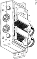
- the Figures 1c and 1d show three-dimensional views of the scraper and its holder 3.
- the free space F extends from the surface of the cutting device 1 in the radial direction (in Fig. 1a to the bottom left).
- the free space F extends between the wiper holder 3 and the fastening mandrel 8, which is inserted through the receiving hole 12 of the frame part 9, see. Fig. 2 ).
- the centers of the two cylindrical cutting devices 1 and 1 'from Fig. 1e connects the free space F in this example from the azimuthal angle 115 ° to 153 ° in Clockwise.
- the free space F thus extends in this example over an azimuthal angular range ⁇ of 38 °.
- a shredder device which has two counter-rotatable cylindrical cutting devices 1, 1 '(direction of rotation D and D').
- a transport roller pair 11, 11 ' By means of a transport roller pair 11, 11 ', the value documents are fed along the transport path of the shredding device and shredded by it.
- the cutting devices 1, 1 ' are formed axially symmetrical to each other and arranged so that their cutting edges 10 on the mutually facing front sides V of the two cutting devices intermesh each other, see. Fig. 1a ,
- the Cutting edges 10 of the two cutting devices value documents 20, which are fed along the transport path T of the shredding device, cut into a plurality of Wert collectionschnipsel.
- the Wert sampleschnipsel be sucked down.
- the air flow is not only along the two middle arrows S in the extension of the transport path 20, but also from the left cutter 1 to the bottom left and from the right cutter 1 'to the bottom right. Since there is between the frame 9, 9 'of the free space F, pulled-through Wert collectionschnipsel that get into this space can be sucked down.
- Fig. 2 shows a 3D view of the shredding device from below, ie viewed from the output side, where the Wert collectionschnipsel be transported out of the shredder device.
- a further embodiment of the shredding device is shown in which a different shape of the stripping elements 2 has been selected.
- the angle vertex of the two angle legs of the stripping elements 2 is substantially further away from the surface of the cutting device than in the stripping elements 2 Fig. 1a-e , As a result, the distance between the stripping elements at the lowest angular position of the cutting device is substantially greater, and the holder 3 of the stripping elements 2 can be placed further away from the cylindrical cutting device 1.
Landscapes
- Engineering & Computer Science (AREA)
- Food Science & Technology (AREA)
- Crushing And Pulverization Processes (AREA)
Claims (13)
- Dispositif de broyage de documents de valeur (20) comprenant au moins deux équipements de découpe (1, 1') cylindriques pouvant tourner en sens opposé l'un par rapport à l'autre qui, par rapport à un chemin de transport (T) des documents de valeur (20), se font face, et qui, à leur surface, comportent respectivement une pluralité d'arêtes de découpe (10), cependant que les arêtes de découpe des deux équipements de découpe s'engagent mutuellement aux côtés antérieurs (V) tournés l'un vers l'autre des deux équipements de découpe afin de, à l'aide des arêtes de découpe, cisailler en une pluralité de petits morceaux les documents de valeur (20) acheminés le long du chemin de transport (T), cependant que chacun des équipements de découpe (1, 1') est affecté à un racleur comportant plusieurs éléments de raclage (2, 2') parallèles entre eux qui sont agencés de telle façon que les éléments de raclage (2, 2') s'engagent entre les arêtes de découpe (10) de l'équipement de découpe respectif afin d'enlever les petits morceaux de documents de valeurs des arêtes de découpe (10) de l'équipement de découpe respectif,- que la forme des éléments de raclage (2, 2') est choisie de telle façon que les éléments de raclage (2, 2'), au côté antérieur (V), de l'équipement de découpe respectif, tourné vers le chemin de transport (T) des documents de valeur, s'engagent entre les arêtes de découpe (10) de l'équipement de découpe respectif,caractérisé en ce- que les éléments de raclage présentent, à la position angulaire la plus inférieure de l'équipement de découpe, un espacement radial (d) d'au moins 10 mm par rapport à la surface de l'équipement de découpe, et- que la forme des éléments de raclage est choisie de telle façon que l'espacement (d) des éléments de raclage par rapport à la surface de l'équipement de découpe s'accroît continuellement, le long de la direction de rotation (D) de l'équipement de découpe, à partir d'une section angulaire azimutale de chevauchement (ω) de l'équipement de découpe dans laquelle les éléments de raclage (2, 2') respectifs se chevauchent avec le contour extérieur (K) de l'équipement de découpe (1, 1') respectif.
- Dispositif selon la revendication 1, caractérisé en ce que le racleur n'entoure l'équipement de découpe (1, 1') respectif qu'au côté antérieur tourné vers le chemin de transport (T) et au côté inférieur de l'équipement de découpe (1, 1').
- Dispositif selon une des revendications précédentes, caractérisé en ce que les petits morceaux de documents de valeur atteignent après le cisaillement des documents de valeur la section angulaire azimutale de chevauchement (ω) de l'équipement de découpe dans laquelle les éléments de raclage (2, 2') respectifs se chevauchent avec le contour extérieur (K) de l'équipement de découpe (1, 1') respectif.
- Dispositif selon une des revendications précédentes, caractérisé en ce que la section angulaire de chevauchement (ω) de l'équipement de découpe respectif dans laquelle les éléments de raclage se chevauchent avec le contour extérieur (K) de l'équipement de découpe respectif - vue le long de la direction de rotation de l'équipement de découpe - se trouve dans une zone angulaire azimutale comprise entre 20° et 100° après la ligne de jonction (L) des deux équipements de découpe (1, 1') cylindriques, en particulier entre 20° et 80°.
- Dispositif selon une des revendications précédentes, caractérisé en ce que la forme des éléments de raclage (2) est choisie de telle façon que la section angulaire de chevauchement (ω) dans laquelle les éléments de raclage et le contour extérieur (K) de l'équipement de découpe se chevauchent s'étend au maximum sur 50°, de préférence au maximum sur 40°.
- Dispositif selon une des revendications précédentes, caractérisé en ce que des éléments de raclage (2, 2') voisins entre eux de l'équipement de découpe (1, 1') respectif sont séparés les uns des autres par respectivement un élément d'espacement (4) agencé à l'extérieur de l'équipement de découpe (1, 1') respectif.
- Dispositif selon la revendication 6, caractérisé en ce que le côté des éléments d'espacement (4) tournés vers l'équipement de découpe respectif présente un espacement radial (c) d'au maximum 1 mm par rapport au contour extérieur (K) de l'équipement de découpe respectif.
- Dispositif selon une des revendications précédentes, caractérisé en ce que des éléments de raclage (2, 2') ont essentiellement la forme de deux branches d'angle qui incluent un angle intérieur compris entre 110° et 160°.
- Dispositif selon une des revendications précédentes, caractérisé en ce que, au côté arrière (R) de l'équipement de découpe respectif, en direction radiale, il y a un espace libre (F) qui s'étend depuis la surface de l'équipement de découpe en direction radiale en particulier sur une profondeur d'au moins 3 cm.
- Dispositif selon la revendication 9, caractérisé en ce que la zone angulaire (δ) azimutale de l'équipement de découpe dans laquelle s'étend l'espace libre (F) en direction radiale sur une profondeur d'au moins 3 cm est d'au moins 30°.
- Dispositif selon la revendication 9 ou 10, caractérisé en ce que l'espace libre (F) se trouve dans une zone angulaire azimutale comprise entre 90° et 180° après la ligne de jonction (L) des deux équipements de découpe cylindriques.
- Dispositif selon une des revendications précédentes, caractérisé en ce que les éléments de raclage (2, 2') et les élément d'espacement (4) sont fixés dans un logement situé à l'extérieur de l'équipement de découpe, en particulier dans un bac (3) rempli de colle.
- Dispositif de traitement de documents de valeur, comprenant :- un dispositif de broyage pour le broyage de documents de valeur selon une des revendications précédentes, et- un équipement de transport (11, 11') pour le transport des documents de valeur (20) et pour l'acheminement des documents de valeur au dispositif de broyage.
Applications Claiming Priority (2)
| Application Number | Priority Date | Filing Date | Title |
|---|---|---|---|
| DE102014016920.0A DE102014016920A1 (de) | 2014-11-17 | 2014-11-17 | Vorrichtung zum Schreddern von Wertdokumenten |
| PCT/EP2015/002289 WO2016078756A1 (fr) | 2014-11-17 | 2015-11-16 | Destructur de documents de valeur |
Publications (2)
| Publication Number | Publication Date |
|---|---|
| EP3221055A1 EP3221055A1 (fr) | 2017-09-27 |
| EP3221055B1 true EP3221055B1 (fr) | 2019-02-27 |
Family
ID=54548131
Family Applications (1)
| Application Number | Title | Priority Date | Filing Date |
|---|---|---|---|
| EP15795115.3A Active EP3221055B1 (fr) | 2014-11-17 | 2015-11-16 | Destructeur de documents de valeur |
Country Status (5)
| Country | Link |
|---|---|
| US (1) | US10737274B2 (fr) |
| EP (1) | EP3221055B1 (fr) |
| AU (1) | AU2015349024B2 (fr) |
| DE (1) | DE102014016920A1 (fr) |
| WO (1) | WO2016078756A1 (fr) |
Families Citing this family (4)
| Publication number | Priority date | Publication date | Assignee | Title |
|---|---|---|---|---|
| DE202017100714U1 (de) * | 2017-02-09 | 2018-05-11 | Hugo Vogelsang Maschinenbau Gmbh | Zerkleinerungsvorrichtung |
| EP4082346B1 (fr) * | 2019-12-23 | 2025-08-13 | Sanyo Foods Co., Ltd. | Dispositif de coupe de nouilles, dispositif de production de nouilles, nouilles et procédé de production de nouilles instantanées |
| DE202020102630U1 (de) | 2020-05-11 | 2021-08-12 | Vogelsang Gmbh & Co. Kg | Zerkleinerungsvorrichtung |
| CN112207112B (zh) * | 2020-09-09 | 2021-12-03 | 北京汇潮云集科技有限公司 | 一种垃圾热解发电装置 |
Family Cites Families (34)
| Publication number | Priority date | Publication date | Assignee | Title |
|---|---|---|---|---|
| DE244761C (fr) | ||||
| US2364533A (en) * | 1941-02-10 | 1944-12-05 | Aldrich L Jackson | Electric meat tenderizer |
| GB629181A (en) | 1947-01-14 | 1949-09-14 | Sunbeam Commercial Vehicles Lt | A new or improved machine for shredding paper and like material |
| US3286574A (en) * | 1964-04-22 | 1966-11-22 | Durand Auguste Paul | Paper slitting apparatus |
| US3931935A (en) * | 1974-06-24 | 1976-01-13 | Holman Merle A | Method of and apparatus for cutting vehicle tires |
| GB2096919B (en) * | 1981-03-11 | 1984-12-05 | Matsushita Electric Industrial Co Ltd | Shredder |
| DE3311331C2 (de) * | 1983-03-29 | 1986-10-23 | Hermann 7777 Salem Schwelling | Abstreifersystem für die Schneid- oder Reißwalzen von Aktenvernichtern |
| US4607800A (en) * | 1983-10-24 | 1986-08-26 | Barclay Randel L | Solid waste comminution machine |
| US4702422A (en) * | 1986-09-19 | 1987-10-27 | Disposable Waste Systems, Inc. | Solid waste comminutor with slotted slide rails and side rails for same |
| GB8626602D0 (en) | 1986-11-07 | 1986-12-10 | Nicholls Eng Services Ltd | Paper shredding apparatus |
| US4889291A (en) * | 1988-03-04 | 1989-12-26 | Feinwerktechnik Schleicher & Co. | Strip-off device for shedding machines with sheet material grid engaging between shredding disks |
| DE8908903U1 (de) | 1989-07-21 | 1989-10-26 | Skiera, Werner, 6909 Walldorf | Mini-Papierzerkleinerer |
| DE4106792C1 (fr) * | 1991-03-04 | 1992-08-27 | Geha-Werke Gmbh, 3000 Hannover, De | |
| US5285707A (en) * | 1991-10-11 | 1994-02-15 | Allegheny Paper Shredders, Inc. | Tire cutting machine |
| DE4212151A1 (de) | 1992-04-10 | 1993-10-14 | Gao Ges Automation Org | Verfahren zur Funktionsüberwachung von mechanischen Papiervernichtern |
| US5342236A (en) * | 1993-05-12 | 1994-08-30 | Milton Industries, Inc. | Meat cutter |
| US5562255A (en) * | 1995-04-04 | 1996-10-08 | Witko; Zbigniew J. | Combined primary and secondary tire shears |
| US5954280A (en) * | 1998-05-12 | 1999-09-21 | Fellowes Manufacturing Company | Top blocker for a paper shredder |
| US5921482A (en) * | 1998-11-13 | 1999-07-13 | Sysgration Ltd. | Structure for paper shredder in a waste paper disposer |
| US6241170B1 (en) * | 2000-01-21 | 2001-06-05 | Cd Systems Inc. | Industrial shredders and novel components therefor |
| US6938845B2 (en) | 2001-09-24 | 2005-09-06 | Franklin Miller, Inc. | Twin-shaft comminutor having dissimilar sized cutters |
| US20040104289A1 (en) * | 2002-02-06 | 2004-06-03 | Hermann Schwelling | File shredder |
| ITMI20021673A1 (it) | 2002-07-26 | 2004-01-26 | Satrind Srl | Trituratore industriale a due alberi |
| US6966513B2 (en) * | 2003-01-09 | 2005-11-22 | Frank Chang | Linkage mechanism of paper-cut and anti-block of double-duty shredder |
| US7377201B2 (en) * | 2005-03-03 | 2008-05-27 | Zhui Chen | Food processing apparatus for forming strips, slices and cubes |
| CA2653287C (fr) * | 2008-02-09 | 2018-05-22 | Shred-Tech Corporation | Rail lateral pour une dechiqueteuse avec griffes encastrees |
| US8157014B2 (en) * | 2008-12-12 | 2012-04-17 | Hydril Usa Manufacturing Llc | Subsea solids processing apparatuses and methods |
| JP4438018B1 (ja) * | 2009-06-16 | 2010-03-24 | 日清食品ホールディングス株式会社 | 製麺用切出装置 |
| US8128013B2 (en) * | 2009-09-17 | 2012-03-06 | Doug Bartelt | High efficiency single pass shredder-granulator |
| US8882011B2 (en) * | 2011-06-28 | 2014-11-11 | Fellowes, Inc. | Cutting shaft oil manifold |
| WO2013167497A2 (fr) * | 2012-05-07 | 2013-11-14 | Erdmann Gmbh & Co. Kg | Broyeuse |
| US9610585B2 (en) * | 2013-05-08 | 2017-04-04 | New United Office Equipments Co., Ltd | Shredder support frame |
| US20150328642A1 (en) * | 2014-05-19 | 2015-11-19 | Electronic Recyclers International, Inc. | Shredding device and method for shredding physical media using household electric power |
| US10130952B2 (en) * | 2014-09-24 | 2018-11-20 | Jwc Environmental, Llc | High flow high capture side rails for comminutor |
-
2014
- 2014-11-17 DE DE102014016920.0A patent/DE102014016920A1/de not_active Withdrawn
-
2015
- 2015-11-16 AU AU2015349024A patent/AU2015349024B2/en active Active
- 2015-11-16 WO PCT/EP2015/002289 patent/WO2016078756A1/fr not_active Ceased
- 2015-11-16 EP EP15795115.3A patent/EP3221055B1/fr active Active
- 2015-11-16 US US15/527,444 patent/US10737274B2/en active Active
Non-Patent Citations (1)
| Title |
|---|
| None * |
Also Published As
| Publication number | Publication date |
|---|---|
| WO2016078756A1 (fr) | 2016-05-26 |
| US20170341081A1 (en) | 2017-11-30 |
| US10737274B2 (en) | 2020-08-11 |
| AU2015349024A1 (en) | 2017-05-25 |
| DE102014016920A1 (de) | 2016-05-19 |
| EP3221055A1 (fr) | 2017-09-27 |
| AU2015349024B2 (en) | 2020-10-22 |
Similar Documents
| Publication | Publication Date | Title |
|---|---|---|
| DE1453328C3 (de) | Schneidmesser für eine mit umlaufenden Messerträger versehene Vorrichtung zur Herstellung von Holzschnitzeln | |
| EP3221055B1 (fr) | Destructeur de documents de valeur | |
| DE102007059625B4 (de) | Strangschneidvorrichtung | |
| DE102009037686A1 (de) | Vorrichtung zur Verarbeitung von Rauchartikelabfällen | |
| EP2349661A1 (fr) | Dispositif de compactage | |
| DE102013211774A1 (de) | Erntegutbearbeitungs- und/oder Förderelement für einen Feldhäcksler | |
| EP3829838B1 (fr) | Dispositif et méthode pour la découpe d'une bande dans une pluralité de bandes connectées, dispositif et methode pour la production d'une tige de tabac | |
| EP4241941A2 (fr) | Dispositif et procédé de fabrication d'un boudin de l'industrie de traitement du tabac | |
| DE102023123092A1 (de) | Vorrichtung und Verfahren zum Zerkleinern von Behältern, insbesondere von Flaschen aus Kunststoff | |
| EP2794110B1 (fr) | Granulateur | |
| DE102009046666A1 (de) | Schneidmesser eines Tabakschneiders | |
| DE102018112902B4 (de) | Abstreifelement zum Abstreifen von außen an einer Hohltrommel einer Vorrichtung zum Trennen von miteinander vermischten Stoffen unterschiedlicher Fließfähigkeit anliegenden Stoffresten sowie Vorrichtung mit einem solchen Abstreifelement | |
| EP2759215A1 (fr) | Dispositif et procédé de découpe de tabac dans une balle de tabac | |
| DE9105932U1 (de) | Schneidwalzenpaar für Maispflücker | |
| EP2529834B1 (fr) | Machine de coupe à tambour et boîte à couteaux pour une machine de ce type | |
| DE29803676U1 (de) | Metallfördereinrichtung | |
| DE102020107961B3 (de) | Messerhalterung für ein Schneidmesser, Schneidmesser und Wurst-Trennmaschine | |
| DE705157C (de) | Zerkleinerungsmaschine, insbesondere Wolf, zum Vernichten von Schriftstuecken | |
| DE102021106779B3 (de) | Messerwalze für eine Vorrichtung zum Zerkleinern von Gefriergutblöcken | |
| DE9319071U1 (de) | Schneidwerk für Gartenhäcksler mit Messerwalze | |
| EP4516405A1 (fr) | Dispositif et procédé de broyage de récipients, en particulier de bouteilles en plastique | |
| DE202023104890U1 (de) | Vorrichtung zum Zerkleinern von Behältern, insbesondere von Flaschen aus Kunststoff | |
| DE102024112459A1 (de) | Vorrichtung zum Schneiden einer Bespannung und Verfahren zur Verwendung | |
| EP2625334B1 (fr) | Dispositif de fixation de lames de docteur | |
| DE202025101546U1 (de) | Vorrichtung zum Zerkleinern von Behältern |
Legal Events
| Date | Code | Title | Description |
|---|---|---|---|
| STAA | Information on the status of an ep patent application or granted ep patent |
Free format text: STATUS: THE INTERNATIONAL PUBLICATION HAS BEEN MADE |
|
| PUAI | Public reference made under article 153(3) epc to a published international application that has entered the european phase |
Free format text: ORIGINAL CODE: 0009012 |
|
| STAA | Information on the status of an ep patent application or granted ep patent |
Free format text: STATUS: REQUEST FOR EXAMINATION WAS MADE |
|
| 17P | Request for examination filed |
Effective date: 20170619 |
|
| AK | Designated contracting states |
Kind code of ref document: A1 Designated state(s): AL AT BE BG CH CY CZ DE DK EE ES FI FR GB GR HR HU IE IS IT LI LT LU LV MC MK MT NL NO PL PT RO RS SE SI SK SM TR |
|
| AX | Request for extension of the european patent |
Extension state: BA ME |
|
| DAV | Request for validation of the european patent (deleted) | ||
| DAX | Request for extension of the european patent (deleted) | ||
| RIC1 | Information provided on ipc code assigned before grant |
Ipc: B02C 18/06 20060101ALI20180420BHEP Ipc: B02C 18/22 20060101ALI20180420BHEP Ipc: B02C 18/00 20060101AFI20180420BHEP |
|
| GRAP | Despatch of communication of intention to grant a patent |
Free format text: ORIGINAL CODE: EPIDOSNIGR1 |
|
| STAA | Information on the status of an ep patent application or granted ep patent |
Free format text: STATUS: GRANT OF PATENT IS INTENDED |
|
| INTG | Intention to grant announced |
Effective date: 20180921 |
|
| GRAS | Grant fee paid |
Free format text: ORIGINAL CODE: EPIDOSNIGR3 |
|
| GRAA | (expected) grant |
Free format text: ORIGINAL CODE: 0009210 |
|
| STAA | Information on the status of an ep patent application or granted ep patent |
Free format text: STATUS: THE PATENT HAS BEEN GRANTED |
|
| AK | Designated contracting states |
Kind code of ref document: B1 Designated state(s): AL AT BE BG CH CY CZ DE DK EE ES FI FR GB GR HR HU IE IS IT LI LT LU LV MC MK MT NL NO PL PT RO RS SE SI SK SM TR |
|
| REG | Reference to a national code |
Ref country code: GB Ref legal event code: FG4D Free format text: NOT ENGLISH |
|
| REG | Reference to a national code |
Ref country code: CH Ref legal event code: EP |
|
| REG | Reference to a national code |
Ref country code: AT Ref legal event code: REF Ref document number: 1100551 Country of ref document: AT Kind code of ref document: T Effective date: 20190315 |
|
| REG | Reference to a national code |
Ref country code: IE Ref legal event code: FG4D Free format text: LANGUAGE OF EP DOCUMENT: GERMAN |
|
| REG | Reference to a national code |
Ref country code: DE Ref legal event code: R096 Ref document number: 502015008169 Country of ref document: DE |
|
| REG | Reference to a national code |
Ref country code: NL Ref legal event code: MP Effective date: 20190227 |
|
| REG | Reference to a national code |
Ref country code: LT Ref legal event code: MG4D |
|
| PG25 | Lapsed in a contracting state [announced via postgrant information from national office to epo] |
Ref country code: FI Free format text: LAPSE BECAUSE OF FAILURE TO SUBMIT A TRANSLATION OF THE DESCRIPTION OR TO PAY THE FEE WITHIN THE PRESCRIBED TIME-LIMIT Effective date: 20190227 Ref country code: SE Free format text: LAPSE BECAUSE OF FAILURE TO SUBMIT A TRANSLATION OF THE DESCRIPTION OR TO PAY THE FEE WITHIN THE PRESCRIBED TIME-LIMIT Effective date: 20190227 Ref country code: ES Free format text: LAPSE BECAUSE OF FAILURE TO SUBMIT A TRANSLATION OF THE DESCRIPTION OR TO PAY THE FEE WITHIN THE PRESCRIBED TIME-LIMIT Effective date: 20190227 Ref country code: LT Free format text: LAPSE BECAUSE OF FAILURE TO SUBMIT A TRANSLATION OF THE DESCRIPTION OR TO PAY THE FEE WITHIN THE PRESCRIBED TIME-LIMIT Effective date: 20190227 Ref country code: PT Free format text: LAPSE BECAUSE OF FAILURE TO SUBMIT A TRANSLATION OF THE DESCRIPTION OR TO PAY THE FEE WITHIN THE PRESCRIBED TIME-LIMIT Effective date: 20190627 Ref country code: NO Free format text: LAPSE BECAUSE OF FAILURE TO SUBMIT A TRANSLATION OF THE DESCRIPTION OR TO PAY THE FEE WITHIN THE PRESCRIBED TIME-LIMIT Effective date: 20190527 |
|
| PG25 | Lapsed in a contracting state [announced via postgrant information from national office to epo] |
Ref country code: RS Free format text: LAPSE BECAUSE OF FAILURE TO SUBMIT A TRANSLATION OF THE DESCRIPTION OR TO PAY THE FEE WITHIN THE PRESCRIBED TIME-LIMIT Effective date: 20190227 Ref country code: NL Free format text: LAPSE BECAUSE OF FAILURE TO SUBMIT A TRANSLATION OF THE DESCRIPTION OR TO PAY THE FEE WITHIN THE PRESCRIBED TIME-LIMIT Effective date: 20190227 Ref country code: HR Free format text: LAPSE BECAUSE OF FAILURE TO SUBMIT A TRANSLATION OF THE DESCRIPTION OR TO PAY THE FEE WITHIN THE PRESCRIBED TIME-LIMIT Effective date: 20190227 Ref country code: GR Free format text: LAPSE BECAUSE OF FAILURE TO SUBMIT A TRANSLATION OF THE DESCRIPTION OR TO PAY THE FEE WITHIN THE PRESCRIBED TIME-LIMIT Effective date: 20190528 Ref country code: IS Free format text: LAPSE BECAUSE OF FAILURE TO SUBMIT A TRANSLATION OF THE DESCRIPTION OR TO PAY THE FEE WITHIN THE PRESCRIBED TIME-LIMIT Effective date: 20190627 Ref country code: LV Free format text: LAPSE BECAUSE OF FAILURE TO SUBMIT A TRANSLATION OF THE DESCRIPTION OR TO PAY THE FEE WITHIN THE PRESCRIBED TIME-LIMIT Effective date: 20190227 Ref country code: BG Free format text: LAPSE BECAUSE OF FAILURE TO SUBMIT A TRANSLATION OF THE DESCRIPTION OR TO PAY THE FEE WITHIN THE PRESCRIBED TIME-LIMIT Effective date: 20190527 |
|
| PG25 | Lapsed in a contracting state [announced via postgrant information from national office to epo] |
Ref country code: EE Free format text: LAPSE BECAUSE OF FAILURE TO SUBMIT A TRANSLATION OF THE DESCRIPTION OR TO PAY THE FEE WITHIN THE PRESCRIBED TIME-LIMIT Effective date: 20190227 Ref country code: RO Free format text: LAPSE BECAUSE OF FAILURE TO SUBMIT A TRANSLATION OF THE DESCRIPTION OR TO PAY THE FEE WITHIN THE PRESCRIBED TIME-LIMIT Effective date: 20190227 Ref country code: CZ Free format text: LAPSE BECAUSE OF FAILURE TO SUBMIT A TRANSLATION OF THE DESCRIPTION OR TO PAY THE FEE WITHIN THE PRESCRIBED TIME-LIMIT Effective date: 20190227 Ref country code: AL Free format text: LAPSE BECAUSE OF FAILURE TO SUBMIT A TRANSLATION OF THE DESCRIPTION OR TO PAY THE FEE WITHIN THE PRESCRIBED TIME-LIMIT Effective date: 20190227 Ref country code: SK Free format text: LAPSE BECAUSE OF FAILURE TO SUBMIT A TRANSLATION OF THE DESCRIPTION OR TO PAY THE FEE WITHIN THE PRESCRIBED TIME-LIMIT Effective date: 20190227 Ref country code: IT Free format text: LAPSE BECAUSE OF FAILURE TO SUBMIT A TRANSLATION OF THE DESCRIPTION OR TO PAY THE FEE WITHIN THE PRESCRIBED TIME-LIMIT Effective date: 20190227 Ref country code: DK Free format text: LAPSE BECAUSE OF FAILURE TO SUBMIT A TRANSLATION OF THE DESCRIPTION OR TO PAY THE FEE WITHIN THE PRESCRIBED TIME-LIMIT Effective date: 20190227 |
|
| REG | Reference to a national code |
Ref country code: DE Ref legal event code: R097 Ref document number: 502015008169 Country of ref document: DE |
|
| PG25 | Lapsed in a contracting state [announced via postgrant information from national office to epo] |
Ref country code: PL Free format text: LAPSE BECAUSE OF FAILURE TO SUBMIT A TRANSLATION OF THE DESCRIPTION OR TO PAY THE FEE WITHIN THE PRESCRIBED TIME-LIMIT Effective date: 20190227 Ref country code: SM Free format text: LAPSE BECAUSE OF FAILURE TO SUBMIT A TRANSLATION OF THE DESCRIPTION OR TO PAY THE FEE WITHIN THE PRESCRIBED TIME-LIMIT Effective date: 20190227 |
|
| PLBE | No opposition filed within time limit |
Free format text: ORIGINAL CODE: 0009261 |
|
| STAA | Information on the status of an ep patent application or granted ep patent |
Free format text: STATUS: NO OPPOSITION FILED WITHIN TIME LIMIT |
|
| 26N | No opposition filed |
Effective date: 20191128 |
|
| PG25 | Lapsed in a contracting state [announced via postgrant information from national office to epo] |
Ref country code: SI Free format text: LAPSE BECAUSE OF FAILURE TO SUBMIT A TRANSLATION OF THE DESCRIPTION OR TO PAY THE FEE WITHIN THE PRESCRIBED TIME-LIMIT Effective date: 20190227 |
|
| PG25 | Lapsed in a contracting state [announced via postgrant information from national office to epo] |
Ref country code: TR Free format text: LAPSE BECAUSE OF FAILURE TO SUBMIT A TRANSLATION OF THE DESCRIPTION OR TO PAY THE FEE WITHIN THE PRESCRIBED TIME-LIMIT Effective date: 20190227 |
|
| REG | Reference to a national code |
Ref country code: CH Ref legal event code: PL |
|
| PG25 | Lapsed in a contracting state [announced via postgrant information from national office to epo] |
Ref country code: LU Free format text: LAPSE BECAUSE OF NON-PAYMENT OF DUE FEES Effective date: 20191116 Ref country code: MC Free format text: LAPSE BECAUSE OF FAILURE TO SUBMIT A TRANSLATION OF THE DESCRIPTION OR TO PAY THE FEE WITHIN THE PRESCRIBED TIME-LIMIT Effective date: 20190227 Ref country code: LI Free format text: LAPSE BECAUSE OF NON-PAYMENT OF DUE FEES Effective date: 20191130 Ref country code: CH Free format text: LAPSE BECAUSE OF NON-PAYMENT OF DUE FEES Effective date: 20191130 |
|
| REG | Reference to a national code |
Ref country code: BE Ref legal event code: MM Effective date: 20191130 |
|
| PG25 | Lapsed in a contracting state [announced via postgrant information from national office to epo] |
Ref country code: IE Free format text: LAPSE BECAUSE OF NON-PAYMENT OF DUE FEES Effective date: 20191116 Ref country code: FR Free format text: LAPSE BECAUSE OF NON-PAYMENT OF DUE FEES Effective date: 20191130 |
|
| PG25 | Lapsed in a contracting state [announced via postgrant information from national office to epo] |
Ref country code: BE Free format text: LAPSE BECAUSE OF NON-PAYMENT OF DUE FEES Effective date: 20191130 |
|
| PG25 | Lapsed in a contracting state [announced via postgrant information from national office to epo] |
Ref country code: CY Free format text: LAPSE BECAUSE OF FAILURE TO SUBMIT A TRANSLATION OF THE DESCRIPTION OR TO PAY THE FEE WITHIN THE PRESCRIBED TIME-LIMIT Effective date: 20190227 |
|
| PG25 | Lapsed in a contracting state [announced via postgrant information from national office to epo] |
Ref country code: MT Free format text: LAPSE BECAUSE OF FAILURE TO SUBMIT A TRANSLATION OF THE DESCRIPTION OR TO PAY THE FEE WITHIN THE PRESCRIBED TIME-LIMIT Effective date: 20190227 Ref country code: HU Free format text: LAPSE BECAUSE OF FAILURE TO SUBMIT A TRANSLATION OF THE DESCRIPTION OR TO PAY THE FEE WITHIN THE PRESCRIBED TIME-LIMIT; INVALID AB INITIO Effective date: 20151116 |
|
| REG | Reference to a national code |
Ref country code: AT Ref legal event code: MM01 Ref document number: 1100551 Country of ref document: AT Kind code of ref document: T Effective date: 20201116 |
|
| PG25 | Lapsed in a contracting state [announced via postgrant information from national office to epo] |
Ref country code: AT Free format text: LAPSE BECAUSE OF NON-PAYMENT OF DUE FEES Effective date: 20201116 |
|
| PG25 | Lapsed in a contracting state [announced via postgrant information from national office to epo] |
Ref country code: MK Free format text: LAPSE BECAUSE OF FAILURE TO SUBMIT A TRANSLATION OF THE DESCRIPTION OR TO PAY THE FEE WITHIN THE PRESCRIBED TIME-LIMIT Effective date: 20190227 |
|
| P01 | Opt-out of the competence of the unified patent court (upc) registered |
Effective date: 20230520 |
|
| PGFP | Annual fee paid to national office [announced via postgrant information from national office to epo] |
Ref country code: DE Payment date: 20251118 Year of fee payment: 11 |
|
| PGFP | Annual fee paid to national office [announced via postgrant information from national office to epo] |
Ref country code: GB Payment date: 20251120 Year of fee payment: 11 |