EP3221994B1 - Verfahren und vorrichtung für übertragung und empfang eines referenzsignals - Google Patents
Verfahren und vorrichtung für übertragung und empfang eines referenzsignals Download PDFInfo
- Publication number
- EP3221994B1 EP3221994B1 EP15861697.9A EP15861697A EP3221994B1 EP 3221994 B1 EP3221994 B1 EP 3221994B1 EP 15861697 A EP15861697 A EP 15861697A EP 3221994 B1 EP3221994 B1 EP 3221994B1
- Authority
- EP
- European Patent Office
- Prior art keywords
- grid
- reference signal
- index
- terminal
- grid index
- Prior art date
- Legal status (The legal status is an assumption and is not a legal conclusion. Google has not performed a legal analysis and makes no representation as to the accuracy of the status listed.)
- Active
Links
Images


Classifications
-
- H—ELECTRICITY
- H04—ELECTRIC COMMUNICATION TECHNIQUE
- H04L—TRANSMISSION OF DIGITAL INFORMATION, e.g. TELEGRAPHIC COMMUNICATION
- H04L27/00—Modulated-carrier systems
- H04L27/26—Systems using multi-frequency codes
- H04L27/2601—Multicarrier modulation systems
- H04L27/2602—Signal structure
- H04L27/26035—Maintenance of orthogonality, e.g. for signals exchanged between cells or users, or by using covering codes or sequences
-
- H—ELECTRICITY
- H04—ELECTRIC COMMUNICATION TECHNIQUE
- H04B—TRANSMISSION
- H04B7/00—Radio transmission systems, i.e. using radiation field
- H04B7/02—Diversity systems; Multi-antenna system, i.e. transmission or reception using multiple antennas
- H04B7/04—Diversity systems; Multi-antenna system, i.e. transmission or reception using multiple antennas using two or more spaced independent antennas
- H04B7/06—Diversity systems; Multi-antenna system, i.e. transmission or reception using multiple antennas using two or more spaced independent antennas at the transmitting station
- H04B7/0613—Diversity systems; Multi-antenna system, i.e. transmission or reception using multiple antennas using two or more spaced independent antennas at the transmitting station using simultaneous transmission
- H04B7/0615—Diversity systems; Multi-antenna system, i.e. transmission or reception using multiple antennas using two or more spaced independent antennas at the transmitting station using simultaneous transmission of weighted versions of same signal
- H04B7/0619—Diversity systems; Multi-antenna system, i.e. transmission or reception using multiple antennas using two or more spaced independent antennas at the transmitting station using simultaneous transmission of weighted versions of same signal using feedback from receiving side
- H04B7/0636—Feedback format
- H04B7/0639—Using selective indices, e.g. of a codebook, e.g. pre-distortion matrix index [PMI] or for beam selection
-
- H—ELECTRICITY
- H04—ELECTRIC COMMUNICATION TECHNIQUE
- H04J—MULTIPLEX COMMUNICATION
- H04J11/00—Orthogonal multiplex systems, e.g. using WALSH codes
- H04J11/0023—Interference mitigation or co-ordination
- H04J11/0026—Interference mitigation or co-ordination of multi-user interference
- H04J11/003—Interference mitigation or co-ordination of multi-user interference at the transmitter
-
- H—ELECTRICITY
- H04—ELECTRIC COMMUNICATION TECHNIQUE
- H04L—TRANSMISSION OF DIGITAL INFORMATION, e.g. TELEGRAPHIC COMMUNICATION
- H04L27/00—Modulated-carrier systems
- H04L27/26—Systems using multi-frequency codes
- H04L27/2601—Multicarrier modulation systems
- H04L27/2602—Signal structure
- H04L27/261—Details of reference signals
- H04L27/2613—Structure of the reference signals
-
- H—ELECTRICITY
- H04—ELECTRIC COMMUNICATION TECHNIQUE
- H04L—TRANSMISSION OF DIGITAL INFORMATION, e.g. TELEGRAPHIC COMMUNICATION
- H04L5/00—Arrangements affording multiple use of the transmission path
- H04L5/0001—Arrangements for dividing the transmission path
- H04L5/0014—Three-dimensional division
- H04L5/0023—Time-frequency-space
-
- H—ELECTRICITY
- H04—ELECTRIC COMMUNICATION TECHNIQUE
- H04L—TRANSMISSION OF DIGITAL INFORMATION, e.g. TELEGRAPHIC COMMUNICATION
- H04L5/00—Arrangements affording multiple use of the transmission path
- H04L5/003—Arrangements for allocating sub-channels of the transmission path
- H04L5/0048—Allocation of pilot signals, i.e. of signals known to the receiver
-
- H—ELECTRICITY
- H04—ELECTRIC COMMUNICATION TECHNIQUE
- H04L—TRANSMISSION OF DIGITAL INFORMATION, e.g. TELEGRAPHIC COMMUNICATION
- H04L5/00—Arrangements affording multiple use of the transmission path
- H04L5/003—Arrangements for allocating sub-channels of the transmission path
- H04L5/0058—Allocation criteria
- H04L5/0069—Allocation based on distance or geographical location
-
- H—ELECTRICITY
- H04—ELECTRIC COMMUNICATION TECHNIQUE
- H04L—TRANSMISSION OF DIGITAL INFORMATION, e.g. TELEGRAPHIC COMMUNICATION
- H04L5/00—Arrangements affording multiple use of the transmission path
- H04L5/0091—Signalling for the administration of the divided path, e.g. signalling of configuration information
-
- H—ELECTRICITY
- H04—ELECTRIC COMMUNICATION TECHNIQUE
- H04W—WIRELESS COMMUNICATION NETWORKS
- H04W72/00—Local resource management
- H04W72/20—Control channels or signalling for resource management
- H04W72/23—Control channels or signalling for resource management in the downlink direction of a wireless link, i.e. towards a terminal
-
- H—ELECTRICITY
- H04—ELECTRIC COMMUNICATION TECHNIQUE
- H04W—WIRELESS COMMUNICATION NETWORKS
- H04W72/00—Local resource management
- H04W72/50—Allocation or scheduling criteria for wireless resources
- H04W72/54—Allocation or scheduling criteria for wireless resources based on quality criteria
- H04W72/541—Allocation or scheduling criteria for wireless resources based on quality criteria using the level of interference
-
- H—ELECTRICITY
- H04—ELECTRIC COMMUNICATION TECHNIQUE
- H04B—TRANSMISSION
- H04B7/00—Radio transmission systems, i.e. using radiation field
- H04B7/02—Diversity systems; Multi-antenna system, i.e. transmission or reception using multiple antennas
- H04B7/04—Diversity systems; Multi-antenna system, i.e. transmission or reception using multiple antennas using two or more spaced independent antennas
- H04B7/0413—MIMO systems
- H04B7/0452—Multi-user MIMO systems
-
- H—ELECTRICITY
- H04—ELECTRIC COMMUNICATION TECHNIQUE
- H04B—TRANSMISSION
- H04B7/00—Radio transmission systems, i.e. using radiation field
- H04B7/02—Diversity systems; Multi-antenna system, i.e. transmission or reception using multiple antennas
- H04B7/04—Diversity systems; Multi-antenna system, i.e. transmission or reception using multiple antennas using two or more spaced independent antennas
- H04B7/06—Diversity systems; Multi-antenna system, i.e. transmission or reception using multiple antennas using two or more spaced independent antennas at the transmitting station
- H04B7/0613—Diversity systems; Multi-antenna system, i.e. transmission or reception using multiple antennas using two or more spaced independent antennas at the transmitting station using simultaneous transmission
- H04B7/0615—Diversity systems; Multi-antenna system, i.e. transmission or reception using multiple antennas using two or more spaced independent antennas at the transmitting station using simultaneous transmission of weighted versions of same signal
- H04B7/0617—Diversity systems; Multi-antenna system, i.e. transmission or reception using multiple antennas using two or more spaced independent antennas at the transmitting station using simultaneous transmission of weighted versions of same signal for beam forming
-
- H—ELECTRICITY
- H04—ELECTRIC COMMUNICATION TECHNIQUE
- H04L—TRANSMISSION OF DIGITAL INFORMATION, e.g. TELEGRAPHIC COMMUNICATION
- H04L5/00—Arrangements affording multiple use of the transmission path
- H04L5/003—Arrangements for allocating sub-channels of the transmission path
- H04L5/0053—Allocation of signalling, i.e. of overhead other than pilot signals
-
- H—ELECTRICITY
- H04—ELECTRIC COMMUNICATION TECHNIQUE
- H04W—WIRELESS COMMUNICATION NETWORKS
- H04W72/00—Local resource management
- H04W72/04—Wireless resource allocation
- H04W72/044—Wireless resource allocation based on the type of the allocated resource
-
- H—ELECTRICITY
- H04—ELECTRIC COMMUNICATION TECHNIQUE
- H04W—WIRELESS COMMUNICATION NETWORKS
- H04W84/00—Network topologies
- H04W84/02—Hierarchically pre-organised networks, e.g. paging networks, cellular networks, WLAN [Wireless Local Area Network] or WLL [Wireless Local Loop]
- H04W84/04—Large scale networks; Deep hierarchical networks
- H04W84/042—Public Land Mobile systems, e.g. cellular systems
Definitions
- the present invention relates to wireless communication techniques, and more particularly, to reference signal transmitting and receiving methods and apparatuses and a scheduling method and apparatus.
- the wireless fading channel has a time-variant feature.
- channel information is required to be obtained to realize correlation detection.
- a transmission node transmits a pre-negotiated known signal or sequence.
- a receiving node obtains the channel information through detecting the known signal or sequence.
- the known signal or sequence is referred to as a preamble signal or reference signal.
- LTE/LTE-A system is a typical correlation detection system.
- functions of the reference signal there are 7 kinds of reference signals, which are present as:
- the UERS signal is mainly used for channel estimation and synchronization of Physical Downlink Shared Channel (PDSCH), so as to realize data demodulation.
- Scrambling sequences of the UERS channel are initially configured according to a cell ID of a serving cell (or an adjacent cell ID).
- the scrambling sequence of the downlink UERS may be transmitted via multiple ports of the network side. At present, there are 8 ports may be used for transmitting the UERS reference signal sequence, i.e., port 7, port 8, ..., port 14.
- the UE During Multi-User Multiple-Input Multiple-Output (MU-MIMO) transmission, the UE has two kinds of UERS port configurations and two kinds of scrambling sequence configurations. Therefore, at most 4 layers of UERS based multiplexing transmission are supported, in particular:
- DCI Downlink Control Information
- DCI Downlink Control Information
- ports 7 and 8 adopt the same time-frequency resources and orthogonality is realized through Code Division Multiplexing (CDM) to avoid interference between each other.
- CDM Code Division Multiplexing
- the DMRS of them do not interfere with each other; when they use different nSCID, there may be some interferences.
- n ID i n ID DMRS i by the higher layer.
- the UERS of the current LTE-A is designed based on interference avoidance and interference indulge manner. That is, on one hand, orthogonal transmission of the UERS of each port is ensured as much as possible. On the other hand, for the interference between paired users due to different nSCID on ports 7 and 8, the interference is not controlled and relevant interference information of the interfered user is not provided.
- the base station may have dozens or hundreds of antennas.
- the system may support downlink transmissions of dozens or even hundreds of users in the same time-frequency resources.
- the existing number of UERS ports is obviously not enough for supporting the downlink transmissions of so many users.
- orthogonal resources time-domain, frequency-domain, and code-domain
- the overhead of the reference resources will be rather large.
- KR 2013 0092467 A discloses transmission of grids pointing antenna ports allocated reference symbol resource elements.
- WO 2014/178648 A1 discloses indication of antenna ports used for transmission of demodulation reference symbols (DMRSs).
- the present application provides reference signal transmitting and receiving methods and apparatuses, so as to increase the number of ports supported by the system at the same time with low reference resource overhead, and ensure that the interference of the reference signal is controllable and eliminable, thereby ensuring the reliability of the transmission.
- the conventional technique is improved through a manner based on interference and interference elimination.
- the number of ports supported by the system at the same time may be increased with low reference resource overhead.
- the interference of the reference signal is controllable and eliminable, so as to ensure the reliability of the transmission.
- the maximum number of paired users supported by the downlink demodulation reference signal may be increased.
- the maximum number of MU users supported may increase from 4 to 4 times of the number of grids.
- the technical solution of the present application may ensure the reliability of channel estimation for downlink demodulation reference signal, make the demodulation reference signal controllable and eliminable, and decrease the complexity of the scheduling algorithm.
- the width of the beam after performing beamforming to the antenna becomes narrower.
- a wave beam may be formed in a three dimensional space after performing horizontal and/or vertical beamforming to a two dimensional antenna array.
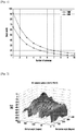
- a space isolation degree formed under a corresponding antenna configuration is determined through analyzing an antenna radiation pattern containing an antenna array gain after beamforming.
- a vertical antenna radiation pattern of each antenna element is A E,V ( ⁇ "), wherein ⁇ " denotes a vertical angle in a local coordinate system of the antenna array.
- a horizontal antenna radiation pattern of each antenna element is A E,H ( ⁇ "), wherein ⁇ " denotes a horizontal angle in the local coordinate system of the antenna array.
- the horizontal dimension of the 2D antenna array includes N antenna elements
- the vertical dimension includes M antenna elements
- the horizontal dimension and the vertical dimension are respectively formed adopting to the beamforming vector WH and WV
- the channel matrix is H
- the antenna radiation pattern after the beamforming is: A " ⁇ " , ⁇ " H ⁇ ( kron W H W V wherein kron denotes matrix direct product calculation,
- the array response in the Line Of Sight (LOS) direction is used to replace the channel matrix H.
- the space isolation degree is relatively low.
- the space isolation degree is relatively high. If two grids are rather far from each other, it may be regarded that users in these two grids do not interfere with each other.
- FIG. 2 shows an antenna radiation pattern with 10 vertical antennas and 1 horizontal antenna. It can be seen that, the antenna radiation concentrates in a relatively small angle (approximately 10 degree) in the vertical dimension, and is distributed in a relatively large area (approximately 65 degree) in the horizontal dimension.
- the beam width becomes narrower and the bean gain is increased, the beam may point to users accurately and avoid interference to other users at the same time.
- the space may be divided into grids. Interference between users in different grids is relatively low but interference between users in the same grids is relatively high.
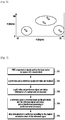
- the present application does not adopt the scheme of the LTE-A system any more, i.e., the scheme in which the same scrambling sequence are adopted for the same cell and the reference signal resources are orthogonal. Instead, a new reference signal transmission method is proposed, as shown in FIG. 3 , the method includes the following:
- a coverage area of the base station is divided into grids, wherein each grid corresponds to a grid index.
- the division of the space may be implemented according to the above-mentioned analysis method.
- the value of 1/X may be configured by considering mobility speed, interference level, complexity, maximum number of users that can be supported, network load and other factors, so as to obtain a reasonable grid size.
- the grids are assigned with the grid indexes according to a certain rule.
- the grid are assigned with the grid indexes according to a space grid sequence (i.e., sequence of the grids in the space), or according to a scrambling sequence of the space grids.
- FIG. 4 is a schematic diagram illustrating a grid division method with fixed size according to an embodiment of the present application. The method includes the following.
- the coverage area of the base station is divided into several grids.
- the whole serving cell may be divided into (Mx, Nx) grids with size( ⁇ X, ⁇ X), wherein
- ⁇ x .
- ⁇ x .
- grid indexes are assigned for the grids.
- the grids may be indexed according to an interference sequence relationship between the grids.
- the corresponding indexes are taken as the grid indexes, e.g., the interference between group 0 and group 1 is larger than that between group 0 and group 2, and so on.
- FIG. 5 is a schematic diagram showing a time-variant and frequency-variant grid division method according to an embodiment of the present application. In this method, the division is performed according to the number of users and data layers multiplexed on the time-frequency resources. As shown in FIG. 5 ,
- the resources in the system bandwidth may be divided into different time-frequency resource blocks.
- the time-frequency resource blocks in the system bandwidth are classified into different types according to different scheduling situations of the UE, e.g., time-frequency resource block supporting single user transmission, time-frequency resource block supporting multi-user single layer transmission, and time-frequency resource block supporting multi-user multi-layer transmission. Different grid divisions are performed on different types of resource blocks.
- the total number of grids may be smaller than or equal to the number of users.
- the total number of grids equals to the number of users.
- FIG. 6 is a schematic diagram illustrating a non-uniform grid division method according to an embodiment of the present application.
- the grids generated in this method are not uniform.
- the grid mentioned in the present application may be regarded as a kind of resource grid.
- the grid division may be dynamic, e.g. according to current user situations in the system, such that more of users are located in central grids.
- users are scheduled according to the grids and user information, and then the grid indexes and reference signal port indexes are assigned to the users.
- the user information may include a Pre-encoding Matrix Index (PMI), Channel Quality Information (CQI), Rank Indication (RI) or user position information reported by the users, or user position information obtained via system positioning.
- PMI information may include a vertical dimension PMI and a horizontal dimension PMI.
- the user information may also be space channel information obtained via uplink channel estimation utilizing channel reciprocity of uplink and downlink channels.
- the user information may be space channel information obtained via uplink channel estimation utilizing uplink and downlink multipath channel dispersion and symmetry of reflection path.
- a horizontal angle and a vertical angle between the grid and the user may be determined according to the user position information.
- the grid where the user is located may be determined directly.
- the horizontal angle and the vertical angle between the grid and the user may be determined according to the PMI and the space channel information. In case that the division is fixed, the grid where the user is located may be determined directly.
- the horizontal angle and the vertical angle between the grid and the user may be determined according to the user position information. According to a horizontal angle and a vertical angle between different users, interference level between different users may be estimated. If the interference level is higher than a predefined threshold, the users are in the same grid. If the interference level is not higher than the predefined threshold, the users are not located in the same grid. As such, it is determined whether users are located in the same grid in case that the division is performed dynamically.
- the interference level between different users may be estimated according to the PMI or the space channel information and the CQI, RI information. If the interference level is higher than the predefined threshold, the users are in the same grid. If the interference level is not higher than the predefined threshold, the users are not in the same grid. As such, it is possible to determine whether users are located in the same grid in case that the division is performed dynamically.
- grid indexes and reference signal port indexes are assigned to the users. For example, users in the same grid are assigned with the same grid index and different reference signal port indexes. Users in different grids are assigned with different grid indexes.
- the UE is notified of the grid index and reference signal port index of the UE.
- the grid index and the reference signal port index may be transmitted via higher layer signaling, or the grid index may be transmitted via downlink control signaling.
- the UE is notified of a grid index and a reference signal port index of a paired user.
- the paired user refers to a user which adopts the same time-frequency resources for MU-MIMO transmission as the UE.
- the base station Since the base station knows distribution of the users in the grids, the base station knows approximate interference situation of each paired user accordingly. Therefore, this block is optional.
- the base station may select a paired user having a high interference level and notify the UE of the grid index and the corresponding reference signal port index, or not notify, or notify the UE of the grid indexes and reference signal ports numbers of multiple paired users.
- the notification may be realized via higher layer signaling or via downlink control signaling.
- the information in the above block 303 and the information in the above optional block 304 may be transmitted to the UE via the same signaling.
- a reference signal is generated based on the grid index.
- the reference signal i.e., reference signal sequence
- the result is, the reference signal sequences corresponding to different grid indexes are different.
- the reference signal sequences corresponding to the same grid index may be the same or different.
- the reference signal is transmitted in corresponding time-frequency resources according to the grid index and the reference signal port index.
- the reference signal sequences corresponding to different grid indexes may be transmitted in the same resources (the resources may include three dimension: time-domain, frequency-domain, code-domain, any one or any combination of the three dimensions may be considered when implementing the technical solution of the present application), the reference signal sequences corresponding to the same grid index may be transmitted using the same resources or different resources.
- the above blocks 301 and 302 describe the grid division, indexing and assignment of grid index for the UE.
- the transmission method of the reference signal merely the interaction between the base station and the user is cared about in the present application, i.e. the part beginning with block 303.
- the present application also provides a reference signal receiving method as shown in FIG. 7 .
- This method is applied to a UE side. It includes the following.
- PMI is reported or signal used by the base station to locate a UE is transmitted.
- the base station may locate the UE via channel reciprocity through the report of the PMI or the transmission of the uplink reference signal, or the locating may be realized by GPRS or transmitting locating reference signal, etc., or by reporting position information by the UE. Whichever manner is adopted, it is merely required to provide certain position information to the network side by the UE.
- This block is a general block about communication between the UE and the base station, but is not a necessary block of the method. Therefore, the omitting of this block does not affect the implementation of the present application.
- a grid index and a reference signal port index are received.
- a grid index and reference signal port index information of a paired user are received.
- Block 703 is an optional block in the present method. That is, the base station may not transmit the grid index and the reference signal port index information of the paired user to the UE. If the base station transmits the grid index and the reference signal port information of the paired user to the UE, the information of blocks 702 and 703 may be transmitted via the same signaling.
- a reference signal is received based on the grid index and the reference signal port index, and an interference processing is performed when necessary.
- a corresponding reference signal may be generated and resources used by the reference signal may be determined.
- the UE knows its grid index and the grid index of the paired user, and is able to determine the interference situation between the UE and the paired user according to a relationship between the grid indexes and the space position of the grids. If it is regarded that the interference is tolerable, no processing may be performed to the interference brought out by the reference signal of the paired user. If it is regarded that the interference is not tolerable, energy estimation may be performed to the reference signal based on the known reference signal information of the interfering user and then determine whether the interference is tolerable according to a result of the energy estimation.
- interference elimination may be performed when estimating the reference signal based on the known reference signal information of the interfering user. Certainly, if the complexity of the interference elimination is acceptable, it is also possible to directly perform the elimination without the determination.
- the following manner may be adopted: first, determine the space position of the present UE according to the grid index of the present UE and the relationship between the grid index and the grid space position, and determine the space position of the paired user according to the grid index of the paired user and the relationship between the grid index and the grid space position, if the spacing is smaller than a predefined distance, the interference processing is required; otherwise, the interference processing is not required.
- the following manner may be adopted: since the UE knows the grid index of the interfering user, the UE is able to obtain the reference signal sequence transmitted by the paired user based on the grid index of the paired user according to the reference signal sequence generating method. At the same time, since the UE knows the grid index of the paired user, the UE is able to determine the space channel direction of the paired user according to a relationship between the grid index and space position of the user, and further determine the pre-encoding vector of the paired user. Then, based on the channel estimation result without considering the interference elimination, the interference signal may be retrieved. After the interference signal is retrieved, the energy of the interference signal may be calculated and the interference signal may be eliminated. As such, the channel estimation result of the UE may be updated. In order to further improve the channel estimation performance, a multiple iterative manner may be adopted.
- the number of pieces of paired user information notified by the base station may be larger than 1.
- the user may process one or more interferences according to a practical situation.
- data demodulation is performed according to the channel estimation result of the reference signal.
- FIG. 8 is a schematic diagram illustrating a scheduling method according to an embodiment of the present application. The method includes the following.
- a grid size is determined.
- the grid size may be determined according to at least one of the following factors: mobility speed, interference level, complexity, maximum number of users that can be supported, and network load, etc.
- the coverage area of the base station is divided into grids.
- grid indexes are assigned for the grids.
- a grid index of the UE is determined.
- a Pre-encoding Matrix Indicator (PMI) or a signal used for locating the UE by the base station reported by the UE may be received, so as to determine the grid index of the UE.
- PMI Pre-encoding Matrix Indicator
- a candidate paired user is determined according to the grid index.
- the space isolation degree is relatively low.
- the space isolation degree is relatively high. If the positions of two grids are rather far from each other, it may regard that users in these two grids do not interfere with each other. Therefore, in this block, it is possible to select a user with a space position farther than a predefined distance as the candidate paired user according to the grid index of the user and the relationship between the grid index and the space position of the grid.
- scheduling is performed within the scope of the candidate paired user.
- the present application further provides a reference signal transmission apparatus. Its structure is as shown in FIG. 9 , including: a notifying module, a reference signal generating module and a reference signal transmitting module; wherein
- the notifying module is adapted to notify a UE of a grid index and a reference signal port index of the UE; wherein a coverage area of a base station is divided into grids, the grid index of the UE is an index of a grid where the UE is located;
- the reference signal generating module is adapted to generate a reference signal based on the grid index
- the reference signal transmitting module is adapted to transmit the reference signal in corresponding time-frequency resources based on the grid index and the reference signal port index.
- apparatus may further include a grid division module, adapted to divide the coverage area of the base station into the grids, each grid respectively corresponds to one grid index; schedule the UE according to the grid index and user information, assign the grid index and the reference signal port index to the UE; wherein UEs in the same grid are assigned with the same grid index and different reference signal port indexes, users in different grids are assigned with different grid indexes.
- a grid division module adapted to divide the coverage area of the base station into the grids, each grid respectively corresponds to one grid index; schedule the UE according to the grid index and user information, assign the grid index and the reference signal port index to the UE; wherein UEs in the same grid are assigned with the same grid index and different reference signal port indexes, users in different grids are assigned with different grid indexes.
- the apparatus may further include a communication module, adapted to receive PMI or a signal used by the base station for positioning the UE reported by the UE before the notifying module notifies the UE of the grid index and the reference signal port index of the UE.
- a communication module adapted to receive PMI or a signal used by the base station for positioning the UE reported by the UE before the notifying module notifies the UE of the grid index and the reference signal port index of the UE.
- the grid division module is further adapted to determine a grid size, divide the coverage area of the base station into the grids of the grid size, and assign grid indexes for the grids.
- the grid division module is further adapted to determine the grid size according to at least one of: mobility speed, interference level, complexity, maximum number of users supported, and network offload.
- the notifying module is further adapted to notify the UE of a grid index and a reference signal port index of at least one paired user.
- the notifying module is further adapted to select at least one paired user according to an interference level between the UE and other users.
- the reference signal generating module is further adapted to generate the reference signal corresponding to the grid index through deriving an initial sequence of the reference signal using the grid index or according to a mapping relationship between the grid index and a reference signal sequence.
- the reference signal transmitting module is further adapted to transmit reference signal sequences corresponding to different grid indexes using the same resources, and transmit reference signal sequences corresponding to the same grid index using the same or different resources.
- the present application further provides a reference signal receiving apparatus, as shown in FIG. 10 .
- the apparatus includes: an index receiving module and a reference signal receiving module, wherein the index receiving module is adapted to receive a grid index and a reference signal port index of a UE, wherein a coverage area of a base station is divided into grids, the grid index of the UE is an index of a grid where the UE is located; and the reference signal receiving module is adapted to receive a reference signal based on the grid index and the reference signal port index.
- the index receiving module is further adapted to receive a grid index and a reference signal port index of at least one paired user.
- the apparatus as shown in FIG. 10 may further include an interference processing module, adapted to determine whether interference between the UE and the paired user requires interference processing according to a grid index of the UE and a grid index of the pair UE, and a relationship between the grid index and grid space position, if the interference processing is required, perform energy estimation to a reference signal of the paired user according to reference signal information of the paired user, if a result of the energy estimation indicates that the interference processing is required, eliminate the interference based on the reference signal information of the user when performing channel estimation according to the reference signal of the UE.
- an interference processing module adapted to determine whether interference between the UE and the paired user requires interference processing according to a grid index of the UE and a grid index of the pair UE, and a relationship between the grid index and grid space position, if the interference processing is required, perform energy estimation to a reference signal of the paired user according to reference signal information of the paired user, if a result of the energy estimation indicates that the interference processing is required, eliminate the interference
- the interference processing module is further adapted to determine a space position of the UE according to the grid index of the UE and the relationship between the grid index and the grid space position, determine a space channel direction of the paired user according to the grid index of the paired user and the relationship between the grid index and the grid space position, determine a pre-encoding vector of the paired user, retrieve an interference signal according to a channel estimation result without considering interference elimination, and calculating energy of the interference signal.
- the present application further provides a scheduling apparatus, as shown in FIG. 11 .
- the apparatus includes: an index determining module, a pairing module and a scheduling module; wherein the index determining module is adapted to determine a grid index of a UE, wherein a coverage area of a base station is divided into grids, the grid index of the UE is an index of a grid where the UE is located; the pairing module is adapted to determine a candidate paired user based on the grid index; and the scheduling module is adapted to schedule the UE with a scope of the candidate paired user.
- the apparatus as shown in FIG. 11 may further include a grid division module, adapted to determine a grid size, divide the coverage area of the base station into the grids of the grid size, and assign grid indexes for the grids.
- a grid division module adapted to determine a grid size, divide the coverage area of the base station into the grids of the grid size, and assign grid indexes for the grids.
- the grid division module is further adapted to determine the grid size according to at least one of: mobility speed, interference level, complexity, maximum number of users supported, and network offload.
- the apparatus may further include a communication module, adapted to receive PMI or a signal used by the base station for positioning the UE reported by the UE.
- the pairing module is further adapted to select a user with a space position farther than a predefined distance as the candidate paired user according to the grid index of the user and the relationship between the grid index and the grid space position.
Landscapes
- Engineering & Computer Science (AREA)
- Signal Processing (AREA)
- Computer Networks & Wireless Communication (AREA)
- Physics & Mathematics (AREA)
- Mathematical Physics (AREA)
- Quality & Reliability (AREA)
- Mobile Radio Communication Systems (AREA)
Claims (12)
- Verfahren zum Betreiben einer Basisstation, BS, in einem drahtlosen Kommunikationssystem, wobei das Verfahren Folgendes umfasst:Übertragen eines Gitterindex und eines Referenzsignalanschlussindex des Endgeräts (303) an ein Endgerät;Erzeugen eines Referenzsignals basierend auf dem Gitterindex (305); undÜbertragen des Referenzsignals auf entsprechenden Zeitfrequenzressourcen basierend auf dem Gitterindex und dem Referenzsignalanschlussindex (306),wobei der Gitterindex eins der Gitter angibt, undwobei jedes der Gitter einem der Bereiche entspricht, die durch Teilen eines Abdeckungsbereichs der Basisstation definiert werden.
- Verfahren nach Anspruch 1, das ferner Folgendes umfasst:Empfangen eines Vorcodierungsmatrixindikators, PMI, oder eines von der Basisstation verwendeten Signals zum Positionieren des Endgeräts, das durch das Endgerät berichtet wird;Teilen des Abdeckungsbereichs der Basisstation in die Gitter, wobei jedes der Gitter jeweils einem Gitterindex entspricht;Planen des Endgeräts gemäß den Gittern und Benutzerinformationen; undZuordnen des Gitterindex und des Referenzsignalanschlussindex zu dem Endgerät,wobei Endgeräte in demselben Gitter mit demselben Gitterindex und unterschiedlichen Referenzsignalanschlussindizes zugeordnet sind und Benutzer in unterschiedlichen Gittern mit unterschiedlichen Gitterindizes zugeordnet sind.
- Verfahren nach Anspruch 2, das ferner Folgendes umfasst:Bestimmen einer Gittergröße;Teilen des Abdeckungsbereichs der Basisstation in die Gitter der Gittergröße; undZuordnen der Gitterindizes für die Gitter, undwobei die Gittergröße gemäß mindestens einem der Folgenden bestimmt wird:
Mobilitätsgeschwindigkeit, Interferenzpegel, Komplexität, Höchstzahl durch Mehrbenutzertechnik unterstützter Benutzer und Netzabladung. - Verfahren nach einem der Ansprüche 1 bis 3, das ferner Folgendes umfasst:Übertragen eines Gitterindex und eines Referenzsignalanschlussindex von mindestens einem gepaarten Benutzer des Endgeräts an das Endgerät; undAuswählen mindestens eines gepaarten Benutzers gemäß einer Interferenzsituation zwischen dem Endgerät und anderen Benutzern.
- Verfahren nach einem der Ansprüche 1 bis 3, das ferner Folgendes umfasst:Ableiten einer anfänglichen Sequenz des Referenzsignals unter Verwendung des Gitterindexes; undErzeugen des Referenzsignals, das dem Gitterindex entspricht, gemäß einer Zuordnungsbeziehung zwischen dem Gitterindex und einer Referenzsignalsequenz.
- Verfahren nach einem der Ansprüche 1 bis 3, das ferner Folgendes umfasst:Übertragen von Referenzsignalsequenzen, die unterschiedlichen Gitterindizes entsprechen, unter Verwendung von selben Ressourcen; undÜbertragen von Referenzsignalsequenzen, die demselben Gitterindex entsprechen, unter Verwendung von selben oder unterschiedlicher Ressourcen.
- Basisstation, BS, in einem drahtlosen Kommunikationssystem, wobei die BS Folgendes umfasst:einen Transceiver, der zum Übertragen eines Gitterindex und eines Referenzsignalanschlussindex des Endgeräts an ein Endgerät konfiguriert ist; undmindestens einen Prozessor, der zum Erzeugen eines Referenzsignals basierend auf dem Gitterindex konfiguriert ist,wobei der Transceiver ferner zum Übertragen des Referenzsignals auf entsprechenden Zeitfrequenzressourcen basierend auf dem Gitterindex und dem Referenzsignalanschlussindex konfiguriert ist,wobei der Gitterindex eins der Gitter angibt, undwobei jedes der Gitter einem der Bereiche entspricht, die durch Teilen eines Abdeckungsbereichs der Basisstation definiert werden.
- Verfahren zum Betreiben eines Endgeräts in einem drahtlosen Kommunikationssystem, wobei das Verfahren Folgendes umfasst:Empfangen eines Gitterindex und eines Referenzsignalanschlussindex des Endgeräts; undEmpfangen eines Referenzsignals auf entsprechenden Zeitfrequenzressourcen basierend auf dem Gitterindex und dem Referenzsignalanschlussindex,wobei das Referenzsignal basierend auf dem Gitterindex erzeugt wird,wobei der Gitterindex eins der Gitter angibt, undwobei jedes der Gitter einem der Bereiche entspricht, die durch Teilen eines Abdeckungsbereichs der Basisstation definiert werden.
- Verfahren nach Anspruch 8, das ferner Folgendes umfasst:Empfangen eines Gitterindex und eines Referenzsignalanschlussindex von mindestens einem gepaarten Benutzer;Bestimmen, ob die Interferenz zwischen dem Endgerät und dem gepaarten Benutzer gemäß dem Gitterindex des Endgeräts und dem Gitterindex des gepaarten Benutzers Interferenzverarbeitung und eine Beziehung zwischen dem Gitterindex und der Gitterplatzposition erfordert;wenn die Interferenzverarbeitung erforderlich ist, Ausführen von Energieschätzung zu einem Referenzsignal des gepaarten Benutzers basierend auf Referenzsignalinformationen des gepaarten Benutzers; undwenn ein Ergebnis der Energieschätzung angibt, dass die Interferenzverarbeitung erforderlich ist, Ausführen einer Interferenzeliminierung basierend auf den Referenzsignalinformationen des gepaarten Benutzers während Kanalschätzung für das Referenzsignal des Endgeräts.
- Verfahren nach Anspruch 9, das ferner Folgendes umfasst:Bestimmen einer Platzposition des Endgeräts gemäß dem Gitterindex des Endgeräts und der Beziehung zwischen dem Gitterindex und der Gitterplatzposition;Bestimmen einer Platzposition des gepaarten Benutzers gemäß dem Gitterindex des gepaarten Benutzers und der Beziehung zwischen dem Gitterindex und der Gitterplatzposition;Bestimmen eines Abstands zwischen dem Endgerät und dem gepaarten Benutzer gemäß den Platzpositionen des Endgeräts und des gepaarten Benutzers, undwenn der Abstand kleiner ist als ein vordefinierter Abstand, Ausführen der Interferenzverarbeitung.
- Verfahren nach Anspruch 9, das ferner Folgendes umfasst:Erhalten einer Referenzsignalsequenz, die durch den gepaarten Benutzer übertragen wird, basierend auf dem Gitterindex des gepaarten Benutzers gemäß einem Referenzsignalsequenzerzeugungsverfahren;Bestimmen einer Platzkanalrichtung des gepaarten Benutzers gemäß der Beziehung zwischen dem Gitterindex und der Gitterplatzposition;Bestimmen eines vorcodierten Vektors des gepaarten Benutzers; undAbrufen eines Interferenzsignals basierend auf einem Kanalschätzungsergebnis ohne Berücksichtigung der Interferenzeliminierung und Berechnen von Energie des Interferenzsignals.
- Endgerät in einem drahtlosen Kommunikationssystem, wobei das Endgerät Folgendes umfasst:
einen Transceiver, der für Folgendes konfiguriert ist:Empfangen eines Gitterindex und eines Referenzsignalanschlussindex des Endgeräts, undEmpfangen eines Referenzsignals auf entsprechenden Zeitfrequenzressourcen basierend auf dem Gitterindex und dem Referenzsignalanschlussindex,wobei das Referenzsignal basierend auf dem Gitterindex erzeugt wird,wobei der Gitterindex eins der Gitter angibt, undwobei jedes der Gitter einem der Bereiche entspricht, die durch Teilen eines Abdeckungsbereichs der Basisstation definiert werden.
Applications Claiming Priority (2)
| Application Number | Priority Date | Filing Date | Title |
|---|---|---|---|
| CN201410665558.1A CN105681007B (zh) | 2014-11-19 | 2014-11-19 | 参考信号的发送、接收方法及装置和调度方法及装置 |
| PCT/KR2015/012451 WO2016080776A1 (en) | 2014-11-19 | 2015-11-19 | Method and apparatus for transmitting and receiving reference signal and for scheduling |
Publications (3)
| Publication Number | Publication Date |
|---|---|
| EP3221994A1 EP3221994A1 (de) | 2017-09-27 |
| EP3221994A4 EP3221994A4 (de) | 2018-02-28 |
| EP3221994B1 true EP3221994B1 (de) | 2020-03-18 |
Family
ID=56014225
Family Applications (1)
| Application Number | Title | Priority Date | Filing Date |
|---|---|---|---|
| EP15861697.9A Active EP3221994B1 (de) | 2014-11-19 | 2015-11-19 | Verfahren und vorrichtung für übertragung und empfang eines referenzsignals |
Country Status (5)
| Country | Link |
|---|---|
| US (1) | US11095354B2 (de) |
| EP (1) | EP3221994B1 (de) |
| KR (1) | KR102418862B1 (de) |
| CN (1) | CN105681007B (de) |
| WO (1) | WO2016080776A1 (de) |
Cited By (1)
| Publication number | Priority date | Publication date | Assignee | Title |
|---|---|---|---|---|
| EP4255005A4 (de) * | 2020-12-23 | 2024-05-15 | ZTE Corporation | Spektrumsressourcenplanungsverfahren und speichermedium |
Families Citing this family (13)
| Publication number | Priority date | Publication date | Assignee | Title |
|---|---|---|---|---|
| KR102188747B1 (ko) * | 2015-10-12 | 2020-12-08 | 에스케이텔레콤 주식회사 | 하이브리드 빔포밍을 이용한 무선 통신 방법 및 장치 |
| US10425140B2 (en) * | 2016-03-09 | 2019-09-24 | Lg Electronics Inc. | Beamforming method and device therefor |
| CN108270470B (zh) * | 2016-12-30 | 2021-02-23 | 华为技术有限公司 | 一种数据传输的方法及发送端设备、接收端设备 |
| US10237754B1 (en) * | 2017-05-12 | 2019-03-19 | Sprint Spectrum L.P. | Minimizing interference in different sectors of wireless networks |
| CN108111271B (zh) * | 2017-06-16 | 2023-09-19 | 中兴通讯股份有限公司 | 参考信号的信令指示、参考信号的发送方法及装置 |
| EP3652906B1 (de) * | 2017-07-13 | 2021-07-28 | Fraunhofer-Gesellschaft zur Förderung der angewandten Forschung e.V. | Interferenzfreie geografische zonale kartierung unter verwendung einer langsam variierenden kanalkovarianzmatrix |
| CN111278116B (zh) | 2018-12-28 | 2022-09-16 | 维沃移动通信有限公司 | 上行信号发送方法及装置 |
| US11476903B1 (en) | 2021-06-17 | 2022-10-18 | Meta Platforms, Inc. | User grouping for multi-user MIMO |
| WO2022265949A1 (en) * | 2021-06-17 | 2022-12-22 | Meta Platforms Technologies, Llc | User grouping for multi-user mimo |
| WO2022266423A1 (en) * | 2021-06-17 | 2022-12-22 | Meta Platforms, Inc. | Hybrid user selection and beamforming method for multi-user mimo |
| CN115733526A (zh) * | 2021-08-31 | 2023-03-03 | 中兴通讯股份有限公司 | 用户配对方法、装置、电子设备和存储介质 |
| CN116054891B (zh) * | 2023-02-13 | 2024-08-16 | 中国联合网络通信集团有限公司 | 多输入多输出系统mu-mimo用户配对方法及装置 |
| CN119835118A (zh) * | 2023-10-13 | 2025-04-15 | 华为技术有限公司 | 一种通信方法及装置 |
Family Cites Families (36)
| Publication number | Priority date | Publication date | Assignee | Title |
|---|---|---|---|---|
| US7363126B1 (en) * | 2002-08-22 | 2008-04-22 | United Parcel Service Of America | Core area territory planning for optimizing driver familiarity and route flexibility |
| US7460583B2 (en) * | 2003-12-15 | 2008-12-02 | Telefonaktiebolaget Lm Ericsson (Publ) | Method for path searching and verification |
| ES2297379T3 (es) * | 2004-02-05 | 2008-05-01 | Telecom Italia S.P.A. | Procedimiento y sistema para la planificacion de la cobertura de radio con enfoque de doble cuadricula local. |
| US7574224B2 (en) * | 2005-06-13 | 2009-08-11 | Qualcomm Incorporated | Methods and apparatus for performing timing synchronization with base stations |
| US7945658B1 (en) * | 2005-12-05 | 2011-05-17 | Narus, Inc. | Method for real-time visualization of BGP analysis and trouble-shooting |
| EP1977563B1 (de) * | 2006-01-11 | 2018-01-03 | QUALCOMM Incorporated | Codierung von bakensignalen zur identifikationsbereitstellung bei der peer-to-peer-kommunikation |
| US7940640B2 (en) | 2006-01-20 | 2011-05-10 | Nortel Networks Limited | Adaptive orthogonal scheduling for virtual MIMO system |
| US7711371B2 (en) * | 2006-06-27 | 2010-05-04 | Motorola, Inc. | Method and system for analysis and visualization of a wireless communications network |
| US8379601B2 (en) | 2007-08-16 | 2013-02-19 | Motorola Mobility Llc | Method and system for selective use of control channel element based implicit pointing |
| DE602008001435D1 (de) * | 2008-03-26 | 2010-07-15 | Ericsson Telefon Ab L M | Verfahren zur Verarbeitung eines Basisbandsignals |
| JP4876100B2 (ja) * | 2008-05-19 | 2012-02-15 | 株式会社エヌ・ティ・ティ・ドコモ | 基地局装置及び方法 |
| US20100172235A1 (en) * | 2009-01-06 | 2010-07-08 | Samsung Electronics Co., Ltd. | System and method for initialization of a scrambling sequence for a downlink reference signal |
| US8321509B2 (en) * | 2009-02-02 | 2012-11-27 | Waldeck Technology, Llc | Handling crowd requests for large geographic areas |
| US20120046995A1 (en) * | 2009-04-29 | 2012-02-23 | Waldeck Technology, Llc | Anonymous crowd comparison |
| US20110019776A1 (en) | 2009-07-24 | 2011-01-27 | Interdigital Patent Holdings, Inc. | Method and apparatus for obtaining port index information |
| US8305987B2 (en) * | 2010-02-12 | 2012-11-06 | Research In Motion Limited | Reference signal for a coordinated multi-point network implementation |
| JP5345111B2 (ja) * | 2010-08-16 | 2013-11-20 | 株式会社エヌ・ティ・ティ・ドコモ | Csi−rsのシグナリング方法及び基地局装置 |
| KR101706040B1 (ko) * | 2010-10-29 | 2017-02-14 | 에스케이 텔레콤주식회사 | 펨토셀 기지국의 커버리지 조절을 위한 시스템 및 방법 |
| US9369885B2 (en) * | 2011-04-12 | 2016-06-14 | Qualcomm Incorporated | Method and apparatus for selecting reference signal tones for decoding a channel |
| US8526961B2 (en) * | 2011-06-29 | 2013-09-03 | Alcatel Lucent | Method and apparatus for mapping operating parameter in coverage area of wireless network |
| CN102883330B (zh) * | 2011-07-13 | 2017-05-31 | 株式会社Ntt都科摩 | 一种异构网络中小区间干扰协调的方法以及异构网络 |
| CN103179658B (zh) * | 2011-12-22 | 2017-04-12 | 华为技术有限公司 | 利用无线信号来定位的方法和定位服务器 |
| KR102133842B1 (ko) * | 2012-02-09 | 2020-07-15 | 엘지전자 주식회사 | 무선 통신 시스템에서 전송 다이버시티 기법을 위한 참조 신호 안테나 포트 할당 방법 및 이를 위한 장치 |
| DE102012202041B4 (de) * | 2012-02-10 | 2022-03-17 | Osram Oled Gmbh | Strahlungsemittierende Vorrichtung |
| US9019924B2 (en) | 2012-04-04 | 2015-04-28 | Samsung Electronics Co., Ltd. | High-order multiple-user multiple-input multiple-output operation for wireless communication systems |
| CN102754475B (zh) * | 2012-04-17 | 2015-04-29 | 华为技术有限公司 | 确定协同多点传输的协作集的方法、装置 |
| CN103581990B (zh) * | 2012-08-08 | 2016-08-10 | 中国移动通信集团河南有限公司 | 一种确定直放站吸收话务量的方法及装置 |
| KR20140067780A (ko) | 2012-11-27 | 2014-06-05 | 삼성전자주식회사 | 무선 통신 시스템에서 간섭 제거를 위한 mimo 전송 방법 및 장치 |
| US9831932B2 (en) | 2013-05-01 | 2017-11-28 | Lg Electronics Inc. | Method for transmitting feedback information through terminal to for split beamforming in wireless communication system and apparatus therefor |
| DE102013013129B4 (de) * | 2013-08-07 | 2023-05-04 | Osram Oled Gmbh | Optoelektronisches Bauelement und Verfahren zur Herstellung eines optoelektronischen Bauelements |
| US10420170B2 (en) * | 2013-10-08 | 2019-09-17 | Parallel Wireless, Inc. | Parameter optimization and event prediction based on cell heuristics |
| CN104009980B (zh) * | 2014-05-13 | 2015-07-22 | 腾讯科技(深圳)有限公司 | 基于社交类应用的通信方法及装置 |
| CN106464319B (zh) * | 2014-05-15 | 2019-09-24 | Lg电子株式会社 | 在无线通信系统中针对3d mimo计算反馈信息的方法和设备 |
| US10028085B2 (en) * | 2014-07-31 | 2018-07-17 | Arizona Board Of Regents On Behalf Of Arizona State University | Distributed location detection in wireless sensor networks |
| US9838847B2 (en) * | 2014-09-11 | 2017-12-05 | Google LLP | Data driven evaluation and rejection of trained Gaussian process-based wireless mean and standard deviation models |
| US10200100B2 (en) * | 2014-11-13 | 2019-02-05 | Lg Electronics Inc. | Method for transmitting and receiving feedback information in wireless communication system and device for same |
-
2014
- 2014-11-19 CN CN201410665558.1A patent/CN105681007B/zh not_active Expired - Fee Related
-
2015
- 2015-11-19 EP EP15861697.9A patent/EP3221994B1/de active Active
- 2015-11-19 WO PCT/KR2015/012451 patent/WO2016080776A1/en not_active Ceased
- 2015-11-19 KR KR1020177016600A patent/KR102418862B1/ko not_active Expired - Fee Related
- 2015-11-19 US US15/528,479 patent/US11095354B2/en not_active Expired - Fee Related
Non-Patent Citations (1)
| Title |
|---|
| None * |
Cited By (1)
| Publication number | Priority date | Publication date | Assignee | Title |
|---|---|---|---|---|
| EP4255005A4 (de) * | 2020-12-23 | 2024-05-15 | ZTE Corporation | Spektrumsressourcenplanungsverfahren und speichermedium |
Also Published As
| Publication number | Publication date |
|---|---|
| CN105681007A (zh) | 2016-06-15 |
| EP3221994A1 (de) | 2017-09-27 |
| KR20170088899A (ko) | 2017-08-02 |
| EP3221994A4 (de) | 2018-02-28 |
| WO2016080776A1 (en) | 2016-05-26 |
| US11095354B2 (en) | 2021-08-17 |
| KR102418862B1 (ko) | 2022-07-08 |
| US20170264355A1 (en) | 2017-09-14 |
| CN105681007B (zh) | 2020-11-06 |
Similar Documents
| Publication | Publication Date | Title |
|---|---|---|
| EP3221994B1 (de) | Verfahren und vorrichtung für übertragung und empfang eines referenzsignals | |
| CN110521135B (zh) | 用于通信波束恢复的系统和方法 | |
| EP3140937B1 (de) | Interferenzmessverfahren und -vorrichtung zur verwendung in einem mobilkommunikationssystem | |
| KR101680400B1 (ko) | 무선 통신 시스템에 있어서 참조 신호를 설치하는 방법 및 시스템 | |
| US9184806B2 (en) | Method for performing hierarchical beamforming in wireless access system and device therefor | |
| CN108886742B (zh) | 5g新无线电中的波束成型公共信道 | |
| EP3522402B1 (de) | Verfahren und vorrichtung zur messung eines kanals in einem drahtloskommunikationssystem | |
| US9148208B2 (en) | Antenna selection codebook for full dimensional MIMO systems | |
| EP3490163B1 (de) | Verfahren und vorrichtung zum empfangen von kanalstatusinformationen in einem mobilkommunikationssystem | |
| US10200100B2 (en) | Method for transmitting and receiving feedback information in wireless communication system and device for same | |
| US10141987B2 (en) | Method for feeding back reference signal information in multi-antenna wireless communication system and apparatus therefor | |
| US8582486B2 (en) | Reference signal transmission method for downlink multiple input multiple output system | |
| EP3200497A1 (de) | Basisstation und benutzervorrichtung | |
| EP3522583B1 (de) | Antennenstrahlverwaltungsverfahren und zugehörige vorrichtung | |
| US20190379433A1 (en) | Methods and devices for feeding back and configuring pilot parameters, user terminal and base station | |
| CN105471552A (zh) | 一种数据传输方法和设备 | |
| KR20160024839A (ko) | 무선 통신 시스템에서 부분 안테나 어레이에 기반한 빔포밍 수행 방법 및 이를 위한 장치 | |
| WO2015064976A2 (ko) | 무선 통신 시스템에서 간섭을 제거하고 신호를 수신하는 방법 및 장치 | |
| WO2014148811A1 (ko) | 무선 통신 시스템에서 간섭을 제거하고 데이터를 수신하는 방법 및 장치 | |
| KR20160114614A (ko) | 무선 통신 시스템에서 대규모 안테나 어레이 기반 빔포밍를 위한 피드백 보고 방법 및 이를 위한 장치 | |
| US20130242896A1 (en) | Method and apparatus for receiving a signal in a wireless communication system that supports mu-mimo scheme | |
| US20140185528A1 (en) | Terminal, base station, communication system, and communication method | |
| KR20150009045A (ko) | 이동 통신 시스템에서 다중 사용자 간섭 측정 방법 및 장치 | |
| US20150245380A1 (en) | Device and Method for Processing Downlink Control Information | |
| CN104284361A (zh) | 一种干扰测量方法、网络侧设备及终端侧设备 |
Legal Events
| Date | Code | Title | Description |
|---|---|---|---|
| STAA | Information on the status of an ep patent application or granted ep patent |
Free format text: STATUS: THE INTERNATIONAL PUBLICATION HAS BEEN MADE |
|
| PUAI | Public reference made under article 153(3) epc to a published international application that has entered the european phase |
Free format text: ORIGINAL CODE: 0009012 |
|
| STAA | Information on the status of an ep patent application or granted ep patent |
Free format text: STATUS: REQUEST FOR EXAMINATION WAS MADE |
|
| 17P | Request for examination filed |
Effective date: 20170614 |
|
| AK | Designated contracting states |
Kind code of ref document: A1 Designated state(s): AL AT BE BG CH CY CZ DE DK EE ES FI FR GB GR HR HU IE IS IT LI LT LU LV MC MK MT NL NO PL PT RO RS SE SI SK SM TR |
|
| AX | Request for extension of the european patent |
Extension state: BA ME |
|
| RIC1 | Information provided on ipc code assigned before grant |
Ipc: H04W 72/04 20090101ALI20171009BHEP Ipc: H04W 72/08 20090101ALI20171009BHEP Ipc: H04W 84/04 20090101ALI20171009BHEP Ipc: H04B 7/0452 20170101ALI20171009BHEP Ipc: H04J 11/00 20060101ALI20171009BHEP Ipc: H04B 7/06 20060101ALI20171009BHEP Ipc: H04L 5/00 20060101AFI20171009BHEP Ipc: H04L 27/26 20060101ALI20171009BHEP |
|
| A4 | Supplementary search report drawn up and despatched |
Effective date: 20180129 |
|
| DAV | Request for validation of the european patent (deleted) | ||
| DAX | Request for extension of the european patent (deleted) | ||
| RIC1 | Information provided on ipc code assigned before grant |
Ipc: H04J 11/00 20060101ALI20180123BHEP Ipc: H04L 27/26 20060101ALI20180123BHEP Ipc: H04W 72/04 20090101ALI20180123BHEP Ipc: H04W 84/04 20090101ALI20180123BHEP Ipc: H04L 5/00 20060101AFI20180123BHEP Ipc: H04B 7/0452 20170101ALI20180123BHEP Ipc: H04W 72/08 20090101ALI20180123BHEP Ipc: H04B 7/06 20060101ALI20180123BHEP |
|
| GRAP | Despatch of communication of intention to grant a patent |
Free format text: ORIGINAL CODE: EPIDOSNIGR1 |
|
| STAA | Information on the status of an ep patent application or granted ep patent |
Free format text: STATUS: GRANT OF PATENT IS INTENDED |
|
| INTG | Intention to grant announced |
Effective date: 20191204 |
|
| GRAS | Grant fee paid |
Free format text: ORIGINAL CODE: EPIDOSNIGR3 |
|
| GRAA | (expected) grant |
Free format text: ORIGINAL CODE: 0009210 |
|
| STAA | Information on the status of an ep patent application or granted ep patent |
Free format text: STATUS: THE PATENT HAS BEEN GRANTED |
|
| AK | Designated contracting states |
Kind code of ref document: B1 Designated state(s): AL AT BE BG CH CY CZ DE DK EE ES FI FR GB GR HR HU IE IS IT LI LT LU LV MC MK MT NL NO PL PT RO RS SE SI SK SM TR |
|
| REG | Reference to a national code |
Ref country code: GB Ref legal event code: FG4D |
|
| REG | Reference to a national code |
Ref country code: DE Ref legal event code: R096 Ref document number: 602015049166 Country of ref document: DE |
|
| REG | Reference to a national code |
Ref country code: AT Ref legal event code: REF Ref document number: 1247146 Country of ref document: AT Kind code of ref document: T Effective date: 20200415 Ref country code: IE Ref legal event code: FG4D |
|
| PG25 | Lapsed in a contracting state [announced via postgrant information from national office to epo] |
Ref country code: NO Free format text: LAPSE BECAUSE OF FAILURE TO SUBMIT A TRANSLATION OF THE DESCRIPTION OR TO PAY THE FEE WITHIN THE PRESCRIBED TIME-LIMIT Effective date: 20200618 Ref country code: FI Free format text: LAPSE BECAUSE OF FAILURE TO SUBMIT A TRANSLATION OF THE DESCRIPTION OR TO PAY THE FEE WITHIN THE PRESCRIBED TIME-LIMIT Effective date: 20200318 Ref country code: RS Free format text: LAPSE BECAUSE OF FAILURE TO SUBMIT A TRANSLATION OF THE DESCRIPTION OR TO PAY THE FEE WITHIN THE PRESCRIBED TIME-LIMIT Effective date: 20200318 |
|
| REG | Reference to a national code |
Ref country code: NL Ref legal event code: MP Effective date: 20200318 |
|
| PG25 | Lapsed in a contracting state [announced via postgrant information from national office to epo] |
Ref country code: GR Free format text: LAPSE BECAUSE OF FAILURE TO SUBMIT A TRANSLATION OF THE DESCRIPTION OR TO PAY THE FEE WITHIN THE PRESCRIBED TIME-LIMIT Effective date: 20200619 Ref country code: BG Free format text: LAPSE BECAUSE OF FAILURE TO SUBMIT A TRANSLATION OF THE DESCRIPTION OR TO PAY THE FEE WITHIN THE PRESCRIBED TIME-LIMIT Effective date: 20200618 Ref country code: LV Free format text: LAPSE BECAUSE OF FAILURE TO SUBMIT A TRANSLATION OF THE DESCRIPTION OR TO PAY THE FEE WITHIN THE PRESCRIBED TIME-LIMIT Effective date: 20200318 Ref country code: SE Free format text: LAPSE BECAUSE OF FAILURE TO SUBMIT A TRANSLATION OF THE DESCRIPTION OR TO PAY THE FEE WITHIN THE PRESCRIBED TIME-LIMIT Effective date: 20200318 Ref country code: HR Free format text: LAPSE BECAUSE OF FAILURE TO SUBMIT A TRANSLATION OF THE DESCRIPTION OR TO PAY THE FEE WITHIN THE PRESCRIBED TIME-LIMIT Effective date: 20200318 |
|
| REG | Reference to a national code |
Ref country code: LT Ref legal event code: MG4D |
|
| PG25 | Lapsed in a contracting state [announced via postgrant information from national office to epo] |
Ref country code: NL Free format text: LAPSE BECAUSE OF FAILURE TO SUBMIT A TRANSLATION OF THE DESCRIPTION OR TO PAY THE FEE WITHIN THE PRESCRIBED TIME-LIMIT Effective date: 20200318 |
|
| PG25 | Lapsed in a contracting state [announced via postgrant information from national office to epo] |
Ref country code: IS Free format text: LAPSE BECAUSE OF FAILURE TO SUBMIT A TRANSLATION OF THE DESCRIPTION OR TO PAY THE FEE WITHIN THE PRESCRIBED TIME-LIMIT Effective date: 20200718 Ref country code: SK Free format text: LAPSE BECAUSE OF FAILURE TO SUBMIT A TRANSLATION OF THE DESCRIPTION OR TO PAY THE FEE WITHIN THE PRESCRIBED TIME-LIMIT Effective date: 20200318 Ref country code: EE Free format text: LAPSE BECAUSE OF FAILURE TO SUBMIT A TRANSLATION OF THE DESCRIPTION OR TO PAY THE FEE WITHIN THE PRESCRIBED TIME-LIMIT Effective date: 20200318 Ref country code: SM Free format text: LAPSE BECAUSE OF FAILURE TO SUBMIT A TRANSLATION OF THE DESCRIPTION OR TO PAY THE FEE WITHIN THE PRESCRIBED TIME-LIMIT Effective date: 20200318 Ref country code: PT Free format text: LAPSE BECAUSE OF FAILURE TO SUBMIT A TRANSLATION OF THE DESCRIPTION OR TO PAY THE FEE WITHIN THE PRESCRIBED TIME-LIMIT Effective date: 20200812 Ref country code: CZ Free format text: LAPSE BECAUSE OF FAILURE TO SUBMIT A TRANSLATION OF THE DESCRIPTION OR TO PAY THE FEE WITHIN THE PRESCRIBED TIME-LIMIT Effective date: 20200318 Ref country code: RO Free format text: LAPSE BECAUSE OF FAILURE TO SUBMIT A TRANSLATION OF THE DESCRIPTION OR TO PAY THE FEE WITHIN THE PRESCRIBED TIME-LIMIT Effective date: 20200318 Ref country code: LT Free format text: LAPSE BECAUSE OF FAILURE TO SUBMIT A TRANSLATION OF THE DESCRIPTION OR TO PAY THE FEE WITHIN THE PRESCRIBED TIME-LIMIT Effective date: 20200318 |
|
| REG | Reference to a national code |
Ref country code: AT Ref legal event code: MK05 Ref document number: 1247146 Country of ref document: AT Kind code of ref document: T Effective date: 20200318 |
|
| REG | Reference to a national code |
Ref country code: DE Ref legal event code: R097 Ref document number: 602015049166 Country of ref document: DE |
|
| PLBE | No opposition filed within time limit |
Free format text: ORIGINAL CODE: 0009261 |
|
| STAA | Information on the status of an ep patent application or granted ep patent |
Free format text: STATUS: NO OPPOSITION FILED WITHIN TIME LIMIT |
|
| PG25 | Lapsed in a contracting state [announced via postgrant information from national office to epo] |
Ref country code: DK Free format text: LAPSE BECAUSE OF FAILURE TO SUBMIT A TRANSLATION OF THE DESCRIPTION OR TO PAY THE FEE WITHIN THE PRESCRIBED TIME-LIMIT Effective date: 20200318 Ref country code: AT Free format text: LAPSE BECAUSE OF FAILURE TO SUBMIT A TRANSLATION OF THE DESCRIPTION OR TO PAY THE FEE WITHIN THE PRESCRIBED TIME-LIMIT Effective date: 20200318 Ref country code: ES Free format text: LAPSE BECAUSE OF FAILURE TO SUBMIT A TRANSLATION OF THE DESCRIPTION OR TO PAY THE FEE WITHIN THE PRESCRIBED TIME-LIMIT Effective date: 20200318 |
|
| 26N | No opposition filed |
Effective date: 20201221 |
|
| PG25 | Lapsed in a contracting state [announced via postgrant information from national office to epo] |
Ref country code: PL Free format text: LAPSE BECAUSE OF FAILURE TO SUBMIT A TRANSLATION OF THE DESCRIPTION OR TO PAY THE FEE WITHIN THE PRESCRIBED TIME-LIMIT Effective date: 20200318 |
|
| PG25 | Lapsed in a contracting state [announced via postgrant information from national office to epo] |
Ref country code: SI Free format text: LAPSE BECAUSE OF FAILURE TO SUBMIT A TRANSLATION OF THE DESCRIPTION OR TO PAY THE FEE WITHIN THE PRESCRIBED TIME-LIMIT Effective date: 20200318 |
|
| PG25 | Lapsed in a contracting state [announced via postgrant information from national office to epo] |
Ref country code: MC Free format text: LAPSE BECAUSE OF FAILURE TO SUBMIT A TRANSLATION OF THE DESCRIPTION OR TO PAY THE FEE WITHIN THE PRESCRIBED TIME-LIMIT Effective date: 20200318 |
|
| REG | Reference to a national code |
Ref country code: CH Ref legal event code: PL |
|
| PG25 | Lapsed in a contracting state [announced via postgrant information from national office to epo] |
Ref country code: LU Free format text: LAPSE BECAUSE OF NON-PAYMENT OF DUE FEES Effective date: 20201119 |
|
| REG | Reference to a national code |
Ref country code: BE Ref legal event code: MM Effective date: 20201130 |
|
| PG25 | Lapsed in a contracting state [announced via postgrant information from national office to epo] |
Ref country code: CH Free format text: LAPSE BECAUSE OF NON-PAYMENT OF DUE FEES Effective date: 20201130 Ref country code: LI Free format text: LAPSE BECAUSE OF NON-PAYMENT OF DUE FEES Effective date: 20201130 |
|
| PG25 | Lapsed in a contracting state [announced via postgrant information from national office to epo] |
Ref country code: IE Free format text: LAPSE BECAUSE OF NON-PAYMENT OF DUE FEES Effective date: 20201119 |
|
| PGFP | Annual fee paid to national office [announced via postgrant information from national office to epo] |
Ref country code: GB Payment date: 20211022 Year of fee payment: 7 |
|
| PGFP | Annual fee paid to national office [announced via postgrant information from national office to epo] |
Ref country code: IT Payment date: 20211025 Year of fee payment: 7 Ref country code: FR Payment date: 20211022 Year of fee payment: 7 |
|
| PG25 | Lapsed in a contracting state [announced via postgrant information from national office to epo] |
Ref country code: TR Free format text: LAPSE BECAUSE OF FAILURE TO SUBMIT A TRANSLATION OF THE DESCRIPTION OR TO PAY THE FEE WITHIN THE PRESCRIBED TIME-LIMIT Effective date: 20200318 Ref country code: MT Free format text: LAPSE BECAUSE OF FAILURE TO SUBMIT A TRANSLATION OF THE DESCRIPTION OR TO PAY THE FEE WITHIN THE PRESCRIBED TIME-LIMIT Effective date: 20200318 Ref country code: CY Free format text: LAPSE BECAUSE OF FAILURE TO SUBMIT A TRANSLATION OF THE DESCRIPTION OR TO PAY THE FEE WITHIN THE PRESCRIBED TIME-LIMIT Effective date: 20200318 |
|
| PG25 | Lapsed in a contracting state [announced via postgrant information from national office to epo] |
Ref country code: MK Free format text: LAPSE BECAUSE OF FAILURE TO SUBMIT A TRANSLATION OF THE DESCRIPTION OR TO PAY THE FEE WITHIN THE PRESCRIBED TIME-LIMIT Effective date: 20200318 Ref country code: AL Free format text: LAPSE BECAUSE OF FAILURE TO SUBMIT A TRANSLATION OF THE DESCRIPTION OR TO PAY THE FEE WITHIN THE PRESCRIBED TIME-LIMIT Effective date: 20200318 |
|
| PG25 | Lapsed in a contracting state [announced via postgrant information from national office to epo] |
Ref country code: BE Free format text: LAPSE BECAUSE OF NON-PAYMENT OF DUE FEES Effective date: 20201130 |
|
| PGFP | Annual fee paid to national office [announced via postgrant information from national office to epo] |
Ref country code: DE Payment date: 20220621 Year of fee payment: 8 |
|
| GBPC | Gb: european patent ceased through non-payment of renewal fee |
Effective date: 20221119 |
|
| PG25 | Lapsed in a contracting state [announced via postgrant information from national office to epo] |
Ref country code: IT Free format text: LAPSE BECAUSE OF NON-PAYMENT OF DUE FEES Effective date: 20221119 Ref country code: GB Free format text: LAPSE BECAUSE OF NON-PAYMENT OF DUE FEES Effective date: 20221119 |
|
| PG25 | Lapsed in a contracting state [announced via postgrant information from national office to epo] |
Ref country code: FR Free format text: LAPSE BECAUSE OF NON-PAYMENT OF DUE FEES Effective date: 20221130 |
|
| REG | Reference to a national code |
Ref country code: DE Ref legal event code: R119 Ref document number: 602015049166 Country of ref document: DE |
|
| PG25 | Lapsed in a contracting state [announced via postgrant information from national office to epo] |
Ref country code: DE Free format text: LAPSE BECAUSE OF NON-PAYMENT OF DUE FEES Effective date: 20240601 |
|
| PG25 | Lapsed in a contracting state [announced via postgrant information from national office to epo] |
Ref country code: DE Free format text: LAPSE BECAUSE OF NON-PAYMENT OF DUE FEES Effective date: 20240601 |