EP3222232B1 - Interspinale prozessfusionsvorrichtung - Google Patents
Interspinale prozessfusionsvorrichtung Download PDFInfo
- Publication number
- EP3222232B1 EP3222232B1 EP17167817.0A EP17167817A EP3222232B1 EP 3222232 B1 EP3222232 B1 EP 3222232B1 EP 17167817 A EP17167817 A EP 17167817A EP 3222232 B1 EP3222232 B1 EP 3222232B1
- Authority
- EP
- European Patent Office
- Prior art keywords
- wings
- movable
- distal tip
- tip member
- actuation
- Prior art date
- Legal status (The legal status is an assumption and is not a legal conclusion. Google has not performed a legal analysis and makes no representation as to the accuracy of the status listed.)
- Active
Links
Images





Classifications
-
- A—HUMAN NECESSITIES
- A61—MEDICAL OR VETERINARY SCIENCE; HYGIENE
- A61B—DIAGNOSIS; SURGERY; IDENTIFICATION
- A61B17/00—Surgical instruments, devices or methods
- A61B17/56—Surgical instruments or methods for treatment of bones or joints; Devices specially adapted therefor
- A61B17/58—Surgical instruments or methods for treatment of bones or joints; Devices specially adapted therefor for osteosynthesis, e.g. bone plates, screws or setting implements
- A61B17/68—Internal fixation devices, including fasteners and spinal fixators, even if a part thereof projects from the skin
- A61B17/70—Spinal positioners or stabilisers, e.g. stabilisers comprising fluid filler in an implant
- A61B17/7062—Devices acting on, attached to, or simulating the effect of, vertebral processes, vertebral facets or ribs ; Tools for such devices
- A61B17/7065—Devices with changeable shape, e.g. collapsible or having retractable arms to aid implantation; Tools therefor
-
- A—HUMAN NECESSITIES
- A61—MEDICAL OR VETERINARY SCIENCE; HYGIENE
- A61B—DIAGNOSIS; SURGERY; IDENTIFICATION
- A61B17/00—Surgical instruments, devices or methods
- A61B17/56—Surgical instruments or methods for treatment of bones or joints; Devices specially adapted therefor
- A61B17/58—Surgical instruments or methods for treatment of bones or joints; Devices specially adapted therefor for osteosynthesis, e.g. bone plates, screws or setting implements
- A61B17/68—Internal fixation devices, including fasteners and spinal fixators, even if a part thereof projects from the skin
- A61B17/70—Spinal positioners or stabilisers, e.g. stabilisers comprising fluid filler in an implant
- A61B17/7071—Implants for expanding or repairing the vertebral arch or wedged between laminae or pedicles; Tools therefor
-
- A—HUMAN NECESSITIES
- A61—MEDICAL OR VETERINARY SCIENCE; HYGIENE
- A61B—DIAGNOSIS; SURGERY; IDENTIFICATION
- A61B17/00—Surgical instruments, devices or methods
- A61B17/56—Surgical instruments or methods for treatment of bones or joints; Devices specially adapted therefor
- A61B17/58—Surgical instruments or methods for treatment of bones or joints; Devices specially adapted therefor for osteosynthesis, e.g. bone plates, screws or setting implements
- A61B17/68—Internal fixation devices, including fasteners and spinal fixators, even if a part thereof projects from the skin
- A61B17/70—Spinal positioners or stabilisers, e.g. stabilisers comprising fluid filler in an implant
- A61B17/7062—Devices acting on, attached to, or simulating the effect of, vertebral processes, vertebral facets or ribs ; Tools for such devices
- A61B17/7067—Devices bearing against one or more spinous processes and also attached to another part of the spine; Tools therefor
-
- A—HUMAN NECESSITIES
- A61—MEDICAL OR VETERINARY SCIENCE; HYGIENE
- A61B—DIAGNOSIS; SURGERY; IDENTIFICATION
- A61B17/00—Surgical instruments, devices or methods
- A61B2017/00831—Material properties
- A61B2017/00858—Material properties high friction or non-slip
Definitions
- the present invention relates to devices implanted between interspinous processes to maintain or reestablish proper spacing within the spine.
- Interspinous process fusion techniques have also been developed. However, these surgical techniques also require moderate to significant soft tissue dissection and there are not true corresponding MIS interspinous process implants. Interspinous process fusion devices are known from US 2009/198337 , US 2011/190816 and US 2009/234389 .
- the disclosed embodiment is designed to enable interspinous process fixation using MIS techniques. In doing so, it will eliminate the technical difficulties inherent to MIS instrumentation with pedicle screws, as well as the soft tissue dissection experienced with ALIF or open interspinous process fixation.
- the present invention provides an interspinous process fusion device that has a distal tip, a middle plate, a proximal plate, an elongate member having a first end and a second end and a longitudinal axis that extends between the first end and the second end, and a plurality of movable wings as defined in independent claim 1.
- Preferred embodiments are set forth in the dependent claims.
- an interspinous process fusion device that typically includes a distal tip, a middle plate, a proximal plate, four fins or wings and three securement screws.
- the terms “interspinous process fusion device”, “device”, “fusion device”, “implant” and “fusion implant” may be used interchangeable as they essentially describe the same type of device. Further, a method of assembling the device is discussed.
- a surgical method for using the interspinous process fusion device to maintain a space between two vertebral bodies within a patient suffering from a diseased or damaged spinal column.
- proximal, distal, anterior, posterior, medial, lateral, superior and inferior are defined by their standard usage for indicating a particular part of a bone or implant according to the relative disposition of the natural bone or directional terms of reference.
- proximal means the portion of an implant nearest the torso
- distal indicates the portion of the implant farthest from the torso.
- anterior is a direction towards the front side of the body
- posterior means a direction towards the back side of the body
- medial means towards the midline of the body
- lateral is a direction towards the sides or away from the midline of the body
- superior means a direction above
- inferior means a direction below another object or structure.
- proximal will mean the portion of the device closest or nearest the insertion instrument.
- distal shall mean the portion of the device farthest away from the insertion instrument.
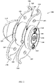
- the device 100 as seen in FIGS. 1 , 2 and 3 has a generally cylindrical geometry with a substantially straight external profile and bulbous or bullet shaped end to facilitate insertion between two spinous processes.
- the implant 100 may likely include a distal tip member 110, a middle plate 120, a plurality of fins or wings 130 and a proximal plate 140.
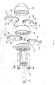
- the device 100 includes in addition to the above noted elements, a locking insert 150, an inner locking screw or central bolt 170 and superior and inferior actuation screws 160.
- FIGS. 1 and 2 also show a means for fixation 180 disposed on the inner surface of wings 130.
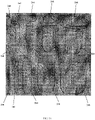
- the means of fixation 180 may include but not be limited to spikes, pins, teeth and a roughed/textured/irregular/grid surface.
- the means for fixation 180 facilitates the capture and securement of the spinous processes between the wings when they are expanded.
- the device 100 includes distal tip member 110, a middle plate 120, a plurality of fins or wings 130 and a proximal plate 140 with a locking insert 150, an inner locking screw 170 and superior and inferior actuation screws 160.
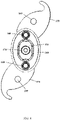
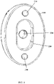
- the distal tip member 110 includes a generally bullet or convex shaped end with a planar surface at the opposite end of the member. The convex end is shaped to facilitate insertion into the body during the operative procedure as well as between the two adjacent spinous processes. The planar end is configured to facilitate the actuation of the two adjacent wings 130 when the device 100 is assembled. As seen in FIG.
- the planar end may include, for example purposes, two outer holes 210 into which the superior and inferior actuation screws may be threaded to actuate and secure the positioning of the wings.
- the central hole 220 is sized to receive the inner locking screw following assembly of the device 100.
- the central depression 230 is configured to receive the locking insert after the locking insert has been positioned through the central aspect of the assembled device 100.
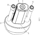
- FIG. 9 shows a perspective view of the device 100 with the wings 130, the middle plate 120 and the proximal plate 140 removed.
- the superior and inferior actuation screws 160 are seen inserted into the corresponding securement holes 210 disposed in the inner planar surface of the distal tip member 110.
- the locking insert 150 is shown positioned within the central depression 230 with the inner locking screw 170 threaded through the locking insert 150 and into the central hole 220 (not shown).
- the middle plate 120 may have two planar ends to facilitate the assembly of the device 100.
- the two ends will articulate with two pairs of wings when the device 100 is constructed.
- the outer shape of the middle plate 120 is oval or oblong to accommodate insertion between the two spinous processes, although other geometric shapes may also be used depending upon the clinical situation.
- the thickness of the middle plate 120 may vary depending upon the clinical situation and patient size. For example purposes, the middle plate thickness may range between 3- 25mm, with a preferred range of 3-15mm.
- Superior and inferior screw holes extend through the entire thickness of the plate to accommodate the passage of the corresponding actuation screws 160. There is a centralized opening that is sized to permit the insertion of the locking insert 150 that then transacts the thickness of the middle plate 120 and extends into the proximately positioned distal tip member 110 for securement.
- device 100 may include more than one intermediate spacer plates as shown. Although the device 100 is described as having a single middle plate 120, a plurality of such plates 120 may be used in the device construct depending upon a presented clinical situation.
- the proximal plate 140 may be similarly constructed to the middle plate 120 in that it may have two planar ends to facilitate the assembly of the device 100.
- the inner end surface of the proximal plate 140 may articulate with one pair of wings when the device 100 is constructed.
- the outer end comprises the end aspect of the device 100.
- the outer shape of the proximal plate 140 is oval or oblong to accommodate placement between the two spinous processes, although other shapes may also be used depending upon the patient's anatomy.
- the thickness of the proximal plate 140 may vary depending upon the clinical situation and patient size. For example purposes, the proximal plate may have a thickness ranging from 2-25mm, with a preferred thickness range of 2-10mm.
- Superior and inferior screw holes extend through the entire thickness of the plate to accommodate the passage of the corresponding actuation screws 160. These holes also may include a counter bore or other like mechanism to accommodate the heads of the actuation screws 160 resulting in the heads being seated below the outer end surface so to eliminate any possible surrounding tissue complications.
- Proximal plate 140 also includes a centralized opening that is sized to permit the insertion of the locking insert 150 that then transacts the thickness through the proximal plate 140 and extends the entire length of the device 100 before seating into the proximately positioned distal tip member 110.
- the outer aspect of the centralized opening may include a counter bore or like configuration that allows the head or end portion of the locking insert to seat below the outer end surface when it has been fully inserted and secured.
- the device 100 typically includes four wings or fins 130 in its structure.
- the fins or wings 130 are movable relative to the proximal plate 140, the middle plate 120 and the distal tip member 110.
- one pair of wings 130 which are in opposing positions are secured between the proximal plate 140 and the middle plate 120.
- a second pair of similarly positioned wings 130 are secured between the middle plate 120 and the distal tip member 110.
- the wings 130 are shown shaped in an arcuate/tear drop configuration to facilitate expansion of the device in vivo. However, other shapes may be used depending upon the given clinical circumstances. Further, the wings 130 are shaped to maximize contact with the spinous processes without interfering with the surrounding soft tissue.
- fixation means 180 Disposed on the outer tip aspect of each wing are fixation means 180, which for example purposes are shown in FIG. 1 as sharpened protrusions. It would be understood that various other means for fixation 180 may be used including spikes, teeth, pins and other heightened surface iterations. Also seen in FIG. 1 are holes 185. Holes 185 may be used to accommodate modular fixation means, including screws, pins and wires as well as being used to facilitate insertion of the device 100. Holes 185 may be numerous for each wing depending upon the given clinical situation. The range of the number of holes in each wing may be between 1-6, with a preferred range of between 1 and 4 holes. Wings 130 also include disposed on the curved inner edge surface, a series of raised teeth or like locking mechanism.
- the teeth are positioned on the inner edge surface of the wing to mechanically interact with a corresponding tooth pattern that is disposed on the top and bottom surface of the locking insert (see FIG. 9 ).
- the top and bottom surfaces of the locking insert 150 each have a corresponding concave trough that runs the length of the insert. Running parallel to and within the trough are a series of raised ribs which will interlock with the teeth of the wings 130.
- the wings 130 may be rotated through the arc of curvature of the inner edge surface and then secured when the appropriate orientation is achieved between the spinous processes.
- the range of rotation as measured from a fully retracted position may be from 0 to 270 degrees, although other degrees of angulation are contemplated.
- each of the wings 130 may also have a plurality of through holes 185 that are used for bone fixation, alignment purposes and securement within the device assembly.
- FIG. 4 shows both the superior and inferior wings 130 locked at 210 degrees from the fully retracted position.
- FIG. 5 shows the superior and inferior wings 130 locked at 150 degrees.
- the locking mechanism for the wings 130 that includes the concave ribbed trough of the locking insert 150 and the teethed portion of the inner edge surface of the wing.
- the superior and inferior wings are generally independent of each allowing the superior and inferior wings 130 to be angled to a different degree to address any anatomical issues or insertion difficulties.
- Wings 130 are moved by a rotation mechanism, which for example purposes may be a press-fit connection between actuation screws 160 and holes 200 in wings 130.
- Other rotation mechanisms are contemplated, including a gear configuration, moveable spline, and camming arrangement.
- FIGS. 10 and 11 show the device 100 following implantation between two spinous processes 300.
- FIG. 10 is a posterior view of the implanted device 100 with the superior spinous process captured between the two superior wings 130 and secured by the means of fixation which contact and grip the bone surface. With the inferior spinous processes, this bone protuberance is also trapped between the two inferior parallel oriented wings 130.
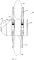
- FIG. 11 is a lateral view showing the device 100 in place following implantation within the spine. Wings 130 are in contact with both lateral surfaces of the two adjacent spinous processes.
- the device 100 is also seen to have an outer configuration such that the external profile of the device 100 does not extend beyond the apex or tip of either of the two processes. Because the device has a low profile, post operative soft tissue complications are decreased or eliminated.
- FIG. 6 shows the locking insert 150 prior to insertion into the centralized opening of the device 100.
- the locking insert 150 may be generally rectangular in shape with an overall length that mirrors the length of the device when assembled. It is contemplated that other cross-sectioned geometrics may also be used in the construction of locking insert 150.
- a central through hole extends the entire length and is sized to allow for the insertion of the inner locking screw 170.
- the entry opening of the centralized hole may include a counter bore or like configuration to accommodate the head of the inner locking screw 170 and avoid potential soft tissue impingement issues.
- the top and bottom surfaces of the locking insert 150 each have a concave trough that runs the length of the insert.
- Running parallel to and within the trough are a series of raised ribs or projections which will interlock with corresponding teeth of the wings 130 to secure the wings position and form a locking mechanism. It is contemplated that other mechanical configurations may be used to accomplish the locking of the wings relative to the locking insert, including possible frictional engagement between the wings 130, and plates 120, 140 and distal tip member 140.
- FIG. 3 also shows inner locking screw 170 and superior and inferior actuation screws 160.
- the inner locking screw 170 is configured to pass through the central portion of the locking insert 150 and then couple to the distal tip member 110.
- the inner locking screw 170 functions to hold all of the components together when the assembly is constructed in a skewer like fashion. It is contemplated that other mechanical fixation devices may be used for this function, including locking pins or rods. For example, a compression o-ring may be used to lock the inner locking screw 170 to the device 100 to prevent backout.
- the superior and inferior actuation screws 160 are positioned above and below the locking insert 150 and may also apply a compressive load on the construct to lock the wings 130 in position.
- the actuation screws 160 extend through all of the elements of the device, including the wings and couple to the distal tip member 110 such that when tightened the actuation screws 160 may apply a compressive load across the entire span of the device 100 to secure all of the elements in position. It should be understood that other alternative modes of fixation may be employed including, but not limited to locking pins and rods.
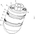
- the device operates in two states, expanded as shown in FIG. 1 and contracted as seen in FIG. 7 .
- the surgeon utilizes the device in its contracted state when it is being implanted during a MIS procedure.
- the device 100 in its contracted position is fully assembled and includes the distal tip member 110, the middle plate 120, the proximal plate 140 with one pair of wings 130 sandwiched between the distal tip member 110 and the middle plate 120 and the second pair of wings 130 between the middle plate 120 and the proximal plate 140.
- Compressing the assembly is a temporary insertion insert 190 that has a configured end that is coupled to an insertion tool (not shown).
- the device 100 In the collapsed state, the device 100 has a uniform or cylindrical like exterior profile that may be described as being bullet shaped.
- the wings 130 have been internally rotated to the extent that the wings outer edges are fully within the outer boundaries/surfaces of the middle and proximal plates, hence producing a uniform outside profile to facilitate implantation.
- a cutting tool 310 may be inserted into the subcutaneous pathway to cut any soft tissue in the path of the wings 130. As illustrated in FIGS. 12 and 13 , the cutting tool 310 may have a handle 312 and a blade 314.
- the method of assembling the device 100 may include the steps of choosing a locking insert 150 sliding the proximal plate 140 over the insert until it abuts the proximal end. A next step may be to insert the superior and inferior actuation screws 160 into the proximal plate 140. The method may then include the step of sliding a first wing 130 onto the superior actuation screw 160 and a first wing 130 onto the inferior actuation screw 160 and sliding both wings 130 until they are adjacent to the proximal plate 140. The method may also include the step of sliding the middle plate along the locking insert 150 and the two actuation screws 160 until the middle plate 120 is adjacent to the previously positioned pair of wings 130.
- the method may also include the step of sliding a second wing 130 onto the superior actuation screw 160 and a second wing 130 onto the inferior actuation screw 160 and sliding both wings 130 until they are adjacent to the middle plate 120.
- the method may include the step of selecting a certain sized distal tip member 110 and sliding this onto the ends of the locking insert 150 and the actuation screws 160. The actuation screws 160 may then be rotated to adjust the angulation of the wings 130 and thereby thread into the distal tip member 110.
- the method may also have the step of inserting the inner locking screw 170 into the centralized hole of the locking insert 150 and then threading the end into corresponding threaded hole disposed within the distal tip member 110 to compress and secure the assembly into one construct.
- biocompatible materials may be used to fabricate the elements, including a myriad of metals, polymers, ceramics and composites. Examples of these include PEEK, titanium and stainless steel.
- the example minimally invasive surgical method for using the device 100 includes the steps of inserting the device subcutaneously between the cephalad or top spinous process and the caudal or bottom spinous process while the device is in its collapsed state with the wings 130 retracted.
- This subcutaneous pathway may be created through an independent incision, or through the DLIF, TLIF, or unilateral decompression of stenosis incision (1 1/2 cm off midline).
- the method may also include the step of positioning the device between the two spinous processes.
- the method may further include the step of deploying the wings 130 in both the cephalad and caudal direction and on both sides of the spinous processes.
- the method may further include the step of compressing the device with the inner locking screw to pressingly engage from a lateral to medial direction the wings 130 with the two sides of the spinous processes. Sharp pins in the wings 130 hold the device in place. Once the device is secured, the tightening instrument is removed and the incision is closed.
- the surgical method for using the device 100 includes the steps of creating an incision at the site where the implant will be inserted. Preparing the site for insertion of the device 100, by for example, chiseling to cut or trim the spinous processes to accept the device 100. Then a series of a plurality of dilators of increasing size may be inserted to expand the space between the spinous processes. For example, a first circular dilator 240 could be inserted into an incision in the patient. Then a second circular dilator 242 with a larger diameter could be inserted over the first dilator 240 to increase the size of the opening. It is also contemplated that only one circular dilator could be used.
- a plurality of circular dilators could be used.
- a third dilator 244 with a slightly oval shape could then be inserted over the second dilator 242 to increase the size of the opening.
- a fourth dilator 246 with a larger oval shape than the third dilator 244 could then be inserted next over the third dilator 244, wherein the first, second, and third dilators 240, 242, 244, respectively, are in a center opening within the fourth dilator 244.
- a plurality of additional dilators could then be inserted over the prior dilator until a dilator having a size that matches the size of the device 100 has been used.
- the dilators may be removed and trials of the device 100 may be inserted through the pathway to a space between the two spinous processes 300 to determine the desired size of the device 100.
- the trials will have exterior sizes that are equivalent to the sizes of the device 100 and may contain a handle for ease of insertion and removal from the patient.
- the trials may have a height of approximately 8 to 16 mm, a width of approximately 4 to 8 mm, and a length of approximately 20mm.
- the plurality of movable wings 130 may be expanded to engage the spinous processes 300. After the plurality of movable wings 130 are expanded the device 100 may be locked in the desired position and the patient may be closed up.
Landscapes
- Health & Medical Sciences (AREA)
- Orthopedic Medicine & Surgery (AREA)
- Life Sciences & Earth Sciences (AREA)
- Neurology (AREA)
- Surgery (AREA)
- Heart & Thoracic Surgery (AREA)
- Engineering & Computer Science (AREA)
- Biomedical Technology (AREA)
- Nuclear Medicine, Radiotherapy & Molecular Imaging (AREA)
- Medical Informatics (AREA)
- Molecular Biology (AREA)
- Animal Behavior & Ethology (AREA)
- General Health & Medical Sciences (AREA)
- Public Health (AREA)
- Veterinary Medicine (AREA)
- Prostheses (AREA)
- Surgical Instruments (AREA)
Claims (15)
- Dornfortsatzfusionsvorrichtung (100), wobei die Vorrichtung Folgendes umfasst:ein distales Spitzenelement (110) mit einem konvex geformten Ende;eine proximale Platte (140);eine mittlere Platte (120), die zwischen dem distalen Spitzenelement (110) und der proximalen Platte (140) angeordnet ist;ein erstes Paar beweglicher Flügel (130), die zwischen dem distalen Spitzenelement (110) und der mittleren Platte (120) positionierbar sind, wobei das erstes Paar beweglicher Flügel (130) einen superioren ersten beweglichen Flügel (130) und einen inferioren ersten beweglichen Flügel (130) aufweist; undein zweites Paar beweglicher Flügel (130), die zwischen der proximalen Platte (140) und der mittleren Platte (120) positionierbar sind, wobei das zweite Paar beweglicher Flügel (130) einen superioren zweiten beweglichen Flügel (130) und einen inferioren zweiten beweglichen Flügel (130) aufweist; undeine erste Betätigungsschraube (160), die mit dem superioren ersten beweglichen Flügel (130) und mit dem superioren zweiten beweglichen Flügel (130) durch ein erstes Loch (200) in dem superioren ersten beweglichen Flügel (130) und in dem superioren zweiten beweglichen Flügel (130) direkt verbunden ist; undeine zweite Betätigungsschraube (160), die mit dem inferioren ersten beweglichen Flügel (130) und dem inferioren zweiten beweglichen Flügel (130) durch ein zweites Loch (200) in dem inferioren ersten beweglichen Flügel (130) und in dem inferioren zweiten beweglichen Flügel (130) direkt verbunden ist,Betrieb der ersten und der zweiten Betätigungsschraube (160), was bewirkt, dass sich jeder der beweglichen Flügel (130) aus einer Einsatzausgestaltung, in der die Vorrichtung eine zylindrische Form aufweist, das erste Paar beweglicher Flügel (130) primär zwischen dem distalen Spitzenelement (110) und der mittleren Platte (120) positioniert ist und das zweite Paar beweglicher Flügel (130) primär zwischen der proximalen Platte (140) und der mittleren Platte (120) positioniert ist, in eine ausgefahrene Ausgestaltung dreht, in der sich die beweglichen Flügel (130) von der proximalen Platte (140), der mittleren Platte (120) und dem distalen Spitzenelement (110) erstrecken.
- Dornfortsatzfusionsvorrichtung (100) nach Anspruch 1, ferner umfassend:
einen Verriegelungseinsatz (150), der ein erstes Ende und ein zweites Ende und eine Längsachse, die sich zwischen dem ersten Ende und dem zweiten Ende erstreckt, aufweist, und eine mittige Bohrung aufweist, die sich zwischen dem ersten Ende und dem zweiten Ende erstreckt. - Dornfortsatzfusionsvorrichtung (100) nach Anspruch 2, ferner umfassend:
eine innere Verriegelungsschraube (170), die in die mittige Bohrung des Verriegelungseinsatzes (150) entlang der Längsachse eingesetzt ist und mit dem distalen Spitzenelement (110) gekoppelt ist. - Dornfortsatzfusionsvorrichtung (100) nach Anspruch 2, ferner umfassend:
einen Verriegelungsmechanismus, der Folgendes umfasst:den Verriegelungseinsatz (150), der eine erste konkave Vertiefung auf einer oberen Oberfläche und eine zweite konkave Vertiefung auf einer unteren Oberfläche aufweist, wobei sich die erste und die zweite konkave Vertiefung zwischen dem ersten Ende und dem zweiten Ende erstrecken und jeweils eine Reihe erhöhter Rippen umfassen; unddie beweglichen Flügel (130), wobei jeder der beweglichen Flügel (130) Zähne aufweist, die auf einer Innenkantenoberfläche der beweglichen Flügel (130) positioniert sind, und die Zähne der beweglichen Flügel (130) so ausgerichtet sind, dass sie die Reihe erhöhter Rippen in mindestens einer von der ersten und zweiten konkaven Vertiefung in Eingriff nehmen. - Dornfortsatzfusionsvorrichtung (100) nach Anspruch 1, ferner umfassend:einen ersten Betätigungskanal (210), der proximal zu dem Verriegelungseinsatz (150) positioniert ist, und wobei der erste Betätigungskanal (210) eine Öffnung in der proximalen Platte (140) aufweist und durch die proximale Platte (140), die mittlere Platte (120), die beweglichen Flügel (130) und in das distale Spitzenelement (110) verläuft; undeinen zweiten Betätigungskanal (210), der distal des Verriegelungseinsatzes (150) positioniert ist, und wobei der zweite Betätigungskanal (210) eine Öffnung in der proximalen Platte (140) aufweist und durch die proximale Platte (140), die mittlere Platte (120), die beweglichen Flügel (130) und in das distale Spitzenelement (110) verläuft.
- Dornfortsatzfusionsvorrichtung (100) nach Anspruch 5, wobei die erste Betätigungsschraube (160) in den ersten Betätigungskanal (210) eingesetzt ist und ein erstes Ende, ein zweites Ende und eine Längsachse, die sich zwischen dem ersten Ende und dem zweiten Ende erstreckt, aufweist, wobei das distale Spitzenelement (110) mit dem ersten Ende der ersten Betätigungsschraube (160) verbunden ist und die proximale Platte (140) mit dem zweiten Ende der ersten Betätigungsschraube (160) und der mittleren Platte (120) verbunden ist, und der superiore erste und der superiore zweite bewegliche Flügel (130) zwischen dem distalen Spitzenelement (110) und der proximalen Platte (140) entlang der Längsachse positioniert sind; und
wobei die zweite Betätigungsschraube (160) in den zweiten Betätigungskanal (210) eingesetzt ist und ein erstes Ende, ein zweites Ende und eine Längsachse, die sich zwischen dem ersten Ende und dem zweiten Ende erstreckt, aufweist, wobei das distale Spitzenelement (110) mit dem ersten Ende der zweiten Betätigungsschraube (160) verbunden ist und die proximale Platte (140) mit dem zweiten Ende der zweiten Betätigungsschraube (160) verbunden ist und die mittlere Platte (120) und der inferiore erste und der inferiore zweite bewegliche Flügel (130) zwischen dem distalen Spitzenelement (110) und der proximalen Platte (140) entlang der Längsachse positioniert sind. - Dornfortsatzfusionsvorrichtung (100) nach Anspruch 6, wobei die erste Betätigungsschraube (160) mit dem superioren ersten und dem superioren zweiten beweglichen Flügel (130) auf einer proximalen Seite der Dornfortsatzfusionsvorrichtung (100) gekoppelt ist und die zweite Betätigungsschraube (160) mit dem inferioren ersten und dem inferioren zweiten beweglichen Flügel (130) auf einer distalen Seite der Dornfortsatzfusionsvorrichtung (100) gekoppelt ist.
- Dornfortsatzfusionsvorrichtung (100) nach Anspruch 7, wobei die erste Betätigungsschraube (160) und die zweite Betätigungsschraube (160) die beweglichen Flügel (130) in Eingriff nehmen, um die Winkelung der beweglichen Flügel (130) in Bezug auf die proximale Platte (140), die mittlere Platte (120) und das distale Spitzenelement (110) anzupassen.
- Dornfortsatzfusionsvorrichtung (100) nach Anspruch 1, wobei die beweglichen Flügel (130) mindestens ein Befestigungsmittel (180) aufweisen.
- Dornfortsatzfusionsvorrichtung (100) nach Anspruch 9, wobei das mindestens eine Befestigungsmittel (180) ausgewählt ist aus der Gruppe bestehend aus geschärften Vorsprüngen, Stacheln, Zähnen, Stiften und einer Wiederholung erhöhter Oberflächen.
- Dornfortsatzfusionsvorrichtung (100) nach Anspruch 1, wobei jeder bewegliche Flügel (130) ein Loch (200) dort hindurch aufweist, das dazu ausgestaltet ist, eine Betätigungsschraube (160) dort hindurch aufzunehmen; und
wobei in der ausgefahrenen Ausgestaltung der superiore erste bewegliche Flügel (130) des ersten Paars Flügel (130) von dem superioren zweiten beweglichen Flügel (130) des zweiten Paars Flügel (130) beabstandet ist, um einen ersten Dornfortsatz dazwischen aufzunehmen, wobei der inferiore erste bewegliche Flügel (130) des ersten Paars Flügel (130) von dem inferioren zweiten beweglichen Flügel (130) des zweiten Paars Flügel (130) beabstandet ist, um einen zweiten Dornfortsatz dazwischen aufzunehmen, wobei das Loch (200) in dem superioren ersten beweglichen Flügel (130) des ersten Paars Flügel (130) an dem Loch (200) in dem superioren zweiten beweglichen Flügel (130) des zweiten Paars Flügel (130) ausgerichtet ist und das Loch (200) in dem inferioren ersten beweglichen Flügel (130) des ersten Paars Flügel (130) an dem Loch (200) in dem inferioren zweiten beweglichen Flügel (130) des zweiten Paars Flügel (130) ausgerichtet ist. - Dornfortsatzfusionsvorrichtung (100) nach Anspruch 11, wobei die beweglichen Flügel (130) mindestens ein Befestigungsmittel (180) aufweisen.
- Dornfortsatzfusionsvorrichtung (100) nach Anspruch 12, wobei das mindestens eine Befestigungsmittel (180) ausgewählt ist aus der Gruppe bestehend aus geschärften Vorsprüngen, Stacheln, Zähnen, Stiften und einer Wiederholung erhöhter Oberflächen.
- Dornfortsatzfusionsvorrichtung (100) nach Anspruch 11, wobei ein erster Betätigungskanal (210) proximal zu dem Verriegelungseinsatz (150) positioniert ist und eine Öffnung in der proximalen Platte (140) aufweist und durch die proximale Platte (140), die mittlere Platte (120), den superioren ersten und den superioren zweiten beweglichen Flügel (130) und in das distale Spitzenelement (110) verläuft und ein zweiter Betätigungskanal (210) distal des Verriegelungseinsatzes (150) positioniert ist und eine Öffnung in der proximalen Platte (140) aufweist und durch die proximale Platte (140), die mittlere Platte (120), den inferioren ersten und den inferioren zweiten beweglichen Flügel (130) und in das distale Spitzenelement (110) verläuft, und wobei die Dornfortsatzfusionsvorrichtung (100) ferner Folgendes umfasst:eine erste Betätigungsschraube (160), die in den ersten Betätigungskanal (210) eingesetzt ist und ein erstes Ende, ein zweites Ende und eine Längsachse, die sich zwischen dem ersten Ende und dem zweiten Ende erstreckt, aufweist, wobei das distale Spitzenelement (110) mit dem ersten Ende der ersten Betätigungsschraube (160) verbunden ist und die proximale Platte (140) mit dem zweiten Ende der ersten Betätigungsschraube (160) und der mittleren Platte (120) verbunden ist und der superiore erste und der superiore zweite bewegliche Flügel (130) zwischen dem distalen Spitzenelement (110) und der proximalen Platte (140) entlang der Längsachse positioniert sind; undeine zweite Betätigungsschraube (160), die in den zweiten Betätigungskanal (210) eingesetzt ist und ein erstes Ende, ein zweites Ende und eine Längsachse, die sich zwischen dem ersten Ende und dem zweiten Ende erstreckt, aufweist, wobei das distale Spitzenelement (110) mit dem ersten Ende der zweiten Betätigungsschraube (160) verbunden ist und die proximale Platte (140) mit dem zweiten Ende der zweiten Betätigungsschraube (160) und der mittleren Platte (120) verbunden ist und der inferiore erste und der inferiore zweite bewegliche Flügel (130) zwischen dem distalen Spitzenelement (110) und der proximalen Platte (140) entlang der Längsachse positioniert sind.
- Dornfortsatzfusionsvorrichtung (100) nach Anspruch 14, wobei die erste Betätigungsschraube (160) den superioren ersten und den superioren zweiten beweglichen Flügel (130) in Eingriff nimmt, um die Winkelung des superioren ersten und des superioren zweiten beweglichen Flügels (130) in Bezug auf die proximale Platte (140), die mittlere Platte (120) und das distale Spitzenelement (110) anzupassen, und wobei die zweite Betätigungsschraube (160) den inferioren ersten und den inferioren zweiten beweglichen Flügel (130) in Eingriff nimmt, um die Winkelung des inferioren ersten und des inferioren zweiten beweglichen Flügels (130) in Bezug auf die proximale Platte (140), die mittlere Platte (120) und das distale Spitzenelement (110) anzupassen.
Applications Claiming Priority (3)
| Application Number | Priority Date | Filing Date | Title |
|---|---|---|---|
| US201161542512P | 2011-10-03 | 2011-10-03 | |
| PCT/US2012/058478 WO2013052496A2 (en) | 2011-10-03 | 2012-10-02 | Interspinous process fusion device and method of use |
| EP12839130.7A EP2763614B1 (de) | 2011-10-03 | 2012-10-02 | Interspinale prozessfusionsvorrichtung |
Related Parent Applications (1)
| Application Number | Title | Priority Date | Filing Date |
|---|---|---|---|
| EP12839130.7A Division EP2763614B1 (de) | 2011-10-03 | 2012-10-02 | Interspinale prozessfusionsvorrichtung |
Publications (2)
| Publication Number | Publication Date |
|---|---|
| EP3222232A1 EP3222232A1 (de) | 2017-09-27 |
| EP3222232B1 true EP3222232B1 (de) | 2022-08-10 |
Family
ID=48044376
Family Applications (2)
| Application Number | Title | Priority Date | Filing Date |
|---|---|---|---|
| EP12839130.7A Active EP2763614B1 (de) | 2011-10-03 | 2012-10-02 | Interspinale prozessfusionsvorrichtung |
| EP17167817.0A Active EP3222232B1 (de) | 2011-10-03 | 2012-10-02 | Interspinale prozessfusionsvorrichtung |
Family Applications Before (1)
| Application Number | Title | Priority Date | Filing Date |
|---|---|---|---|
| EP12839130.7A Active EP2763614B1 (de) | 2011-10-03 | 2012-10-02 | Interspinale prozessfusionsvorrichtung |
Country Status (4)
| Country | Link |
|---|---|
| US (4) | US9393053B2 (de) |
| EP (2) | EP2763614B1 (de) |
| AU (2) | AU2012318811B2 (de) |
| WO (1) | WO2013052496A2 (de) |
Families Citing this family (14)
| Publication number | Priority date | Publication date | Assignee | Title |
|---|---|---|---|---|
| KR20110055608A (ko) | 2008-08-13 | 2011-05-25 | 신세스 게엠바하 | 극돌기간 스페이서 조립체 |
| BR112012010592A2 (pt) * | 2009-11-06 | 2016-03-22 | Synthes Gmbh | implantes e métodos de espaçador de processo interespinhal minimamente invasivo. |
| EP2763614B1 (de) * | 2011-10-03 | 2017-04-26 | In Queue Innovations, LLC | Interspinale prozessfusionsvorrichtung |
| US11812923B2 (en) * | 2011-10-07 | 2023-11-14 | Alan Villavicencio | Spinal fixation device |
| WO2015138948A1 (en) | 2014-03-14 | 2015-09-17 | In Queue Innovations, Llc | Interspinous process fixation devices, systems, instruments and methods of assembly and use |
| ES2955469T3 (es) | 2015-07-31 | 2023-12-01 | Surgalign Spv Inc | Dispositivo de estabilización y fusión interespinosa |
| WO2018035175A1 (en) | 2016-08-15 | 2018-02-22 | In Queue Innovations, Llc | Bone fusion device, system and methods |
| EP3856042B1 (de) | 2018-09-27 | 2025-07-02 | Triqueue Holdings, Llc | Implantatsysteme, platten, knochenfusionssysteme |
| US11723778B1 (en) | 2021-09-23 | 2023-08-15 | Nofusco Corporation | Vertebral implant system and methods of use |
| US12144742B2 (en) | 2020-06-15 | 2024-11-19 | Foundation Surgical Group, Inc. | Implant system and methods of use |
| AU2021292075B2 (en) | 2020-06-15 | 2025-12-18 | Foundation Surgical Group, Inc. | Intravertebral implant system and methods of use |
| US11883300B2 (en) | 2020-06-15 | 2024-01-30 | Nofusco Corporation | Orthopedic implant system and methods of use |
| CN113827379B (zh) | 2020-06-24 | 2025-05-02 | 好喜欢妮有限公司 | 棘突间固定装置 |
| TWI819504B (zh) * | 2022-02-25 | 2023-10-21 | 寶億生技股份有限公司 | 棘突間撐開固定裝置及其穩定裝置 |
Family Cites Families (18)
| Publication number | Priority date | Publication date | Assignee | Title |
|---|---|---|---|---|
| US5390683A (en) * | 1991-02-22 | 1995-02-21 | Pisharodi; Madhavan | Spinal implantation methods utilizing a middle expandable implant |
| US5658335A (en) * | 1995-03-09 | 1997-08-19 | Cohort Medical Products Group, Inc. | Spinal fixator |
| US7008431B2 (en) * | 2001-10-30 | 2006-03-07 | Depuy Spine, Inc. | Configured and sized cannula |
| US9055981B2 (en) * | 2004-10-25 | 2015-06-16 | Lanx, Inc. | Spinal implants and methods |
| FR2887434B1 (fr) * | 2005-06-28 | 2008-03-28 | Jean Taylor | Materiel de traitement chirurgical de deux vertebres |
| US8221462B2 (en) * | 2005-08-01 | 2012-07-17 | Globus Medical, Inc. | Interspinous internal fixation/distraction device |
| US7753938B2 (en) | 2005-08-05 | 2010-07-13 | Synthes Usa, Llc | Apparatus for treating spinal stenosis |
| US20080108990A1 (en) * | 2006-11-02 | 2008-05-08 | St. Francis Medical Technologies, Inc. | Interspinous process implant having a fixed wing and a deployable wing and method of implantation |
| US8142479B2 (en) * | 2007-05-01 | 2012-03-27 | Spinal Simplicity Llc | Interspinous process implants having deployable engagement arms |
| US8105358B2 (en) * | 2008-02-04 | 2012-01-31 | Kyphon Sarl | Medical implants and methods |
| TW200938157A (en) * | 2008-03-11 | 2009-09-16 | Fong-Ying Chuang | Interspinous spine fixing device |
| US8523910B2 (en) * | 2008-04-22 | 2013-09-03 | Globus Medical, Inc. | Lateral spinous process spacer |
| US8945184B2 (en) | 2009-03-13 | 2015-02-03 | Spinal Simplicity Llc. | Interspinous process implant and fusion cage spacer |
| US8157842B2 (en) * | 2009-06-12 | 2012-04-17 | Kyphon Sarl | Interspinous implant and methods of use |
| US8388656B2 (en) * | 2010-02-04 | 2013-03-05 | Ebi, Llc | Interspinous spacer with deployable members and related method |
| EP2763614B1 (de) * | 2011-10-03 | 2017-04-26 | In Queue Innovations, LLC | Interspinale prozessfusionsvorrichtung |
| US11672562B2 (en) * | 2015-09-04 | 2023-06-13 | Medos International Sarl | Multi-shield spinal access system |
| EP3856042B1 (de) * | 2018-09-27 | 2025-07-02 | Triqueue Holdings, Llc | Implantatsysteme, platten, knochenfusionssysteme |
-
2012
- 2012-10-02 EP EP12839130.7A patent/EP2763614B1/de active Active
- 2012-10-02 US US14/349,118 patent/US9393053B2/en active Active
- 2012-10-02 AU AU2012318811A patent/AU2012318811B2/en active Active
- 2012-10-02 EP EP17167817.0A patent/EP3222232B1/de active Active
- 2012-10-02 WO PCT/US2012/058478 patent/WO2013052496A2/en not_active Ceased
-
2016
- 2016-07-15 US US15/211,600 patent/US10154860B2/en active Active
-
2017
- 2017-08-18 AU AU2017216554A patent/AU2017216554B2/en active Active
-
2018
- 2018-12-10 US US16/214,894 patent/US11103289B2/en active Active
-
2021
- 2021-08-30 US US17/446,391 patent/US12156680B2/en active Active
Also Published As
| Publication number | Publication date |
|---|---|
| EP3222232A1 (de) | 2017-09-27 |
| EP2763614A2 (de) | 2014-08-13 |
| US9393053B2 (en) | 2016-07-19 |
| US20190105084A1 (en) | 2019-04-11 |
| US12156680B2 (en) | 2024-12-03 |
| US20140243898A1 (en) | 2014-08-28 |
| WO2013052496A3 (en) | 2013-06-20 |
| EP2763614B1 (de) | 2017-04-26 |
| AU2017216554A1 (en) | 2017-09-07 |
| US10154860B2 (en) | 2018-12-18 |
| US11103289B2 (en) | 2021-08-31 |
| US20210386459A1 (en) | 2021-12-16 |
| US20160317194A1 (en) | 2016-11-03 |
| AU2012318811B2 (en) | 2017-05-18 |
| AU2017216554B2 (en) | 2020-02-06 |
| AU2012318811A1 (en) | 2014-04-24 |
| WO2013052496A2 (en) | 2013-04-11 |
| EP2763614A4 (de) | 2015-12-23 |
Similar Documents
| Publication | Publication Date | Title |
|---|---|---|
| US12156680B2 (en) | Interspinous process fusion device and method of use | |
| US12569282B2 (en) | Tissue retraction and vertebral displacement devices, systems, and methods for posterior spinal fusion | |
| TWI851790B (zh) | 脊柱設備及脊柱系統 | |
| CN103841926B (zh) | 用于颈椎外侧固定的装置 | |
| CN104220017B (zh) | 可套入的棘突间固定装置及使用方法 | |
| JP2022544680A (ja) | 変換式の二軸の調整可能な椎体間固定術の脊椎システム | |
| US20120265301A1 (en) | Intraosseous fixation assembly for an osteotomy and method of use | |
| US20100057127A1 (en) | Expandable Laminoplasty Fixation System | |
| US20080097486A1 (en) | Systems and Methods for Direct Restoration of Foraminal Volume | |
| WO2006118999A2 (en) | Orthopedic instrument | |
| EP1427341A1 (de) | System und verfahren zur stabilisierung des rückgrates | |
| US20220395301A1 (en) | Laminoplasty plates, systems, and devices, and methods relating to the same | |
| US9820864B2 (en) | Disc replacement device and method of use | |
| JP7137792B2 (ja) | 棘突起を治療する装置 | |
| CN112168318A (zh) | 一种胸腰椎侧方可调固定板系统 | |
| EP3116421B1 (de) | Interspinale prozessfixierungsvorrichtungen | |
| CN213641138U (zh) | 一种胸腰椎侧方可调固定板系统 | |
| US8535328B2 (en) | Medical device insertion instrument | |
| AU2002322554A1 (en) | Spinal stabilization system and method |
Legal Events
| Date | Code | Title | Description |
|---|---|---|---|
| PUAI | Public reference made under article 153(3) epc to a published international application that has entered the european phase |
Free format text: ORIGINAL CODE: 0009012 |
|
| STAA | Information on the status of an ep patent application or granted ep patent |
Free format text: STATUS: THE APPLICATION HAS BEEN PUBLISHED |
|
| AC | Divisional application: reference to earlier application |
Ref document number: 2763614 Country of ref document: EP Kind code of ref document: P |
|
| AK | Designated contracting states |
Kind code of ref document: A1 Designated state(s): AL AT BE BG CH CY CZ DE DK EE ES FI FR GB GR HR HU IE IS IT LI LT LU LV MC MK MT NL NO PL PT RO RS SE SI SK SM TR |
|
| STAA | Information on the status of an ep patent application or granted ep patent |
Free format text: STATUS: REQUEST FOR EXAMINATION WAS MADE |
|
| 17P | Request for examination filed |
Effective date: 20180327 |
|
| RBV | Designated contracting states (corrected) |
Designated state(s): AL AT BE BG CH CY CZ DE DK EE ES FI FR GB GR HR HU IE IS IT LI LT LU LV MC MK MT NL NO PL PT RO RS SE SI SK SM TR |
|
| STAA | Information on the status of an ep patent application or granted ep patent |
Free format text: STATUS: EXAMINATION IS IN PROGRESS |
|
| 17Q | First examination report despatched |
Effective date: 20210719 |
|
| GRAP | Despatch of communication of intention to grant a patent |
Free format text: ORIGINAL CODE: EPIDOSNIGR1 |
|
| STAA | Information on the status of an ep patent application or granted ep patent |
Free format text: STATUS: GRANT OF PATENT IS INTENDED |
|
| INTG | Intention to grant announced |
Effective date: 20220406 |
|
| GRAS | Grant fee paid |
Free format text: ORIGINAL CODE: EPIDOSNIGR3 |
|
| GRAA | (expected) grant |
Free format text: ORIGINAL CODE: 0009210 |
|
| STAA | Information on the status of an ep patent application or granted ep patent |
Free format text: STATUS: THE PATENT HAS BEEN GRANTED |
|
| AC | Divisional application: reference to earlier application |
Ref document number: 2763614 Country of ref document: EP Kind code of ref document: P |
|
| AK | Designated contracting states |
Kind code of ref document: B1 Designated state(s): AL AT BE BG CH CY CZ DE DK EE ES FI FR GB GR HR HU IE IS IT LI LT LU LV MC MK MT NL NO PL PT RO RS SE SI SK SM TR |
|
| REG | Reference to a national code |
Ref country code: AT Ref legal event code: REF Ref document number: 1509932 Country of ref document: AT Kind code of ref document: T Effective date: 20220815 Ref country code: CH Ref legal event code: EP |
|
| REG | Reference to a national code |
Ref country code: DE Ref legal event code: R096 Ref document number: 602012078602 Country of ref document: DE |
|
| REG | Reference to a national code |
Ref country code: IE Ref legal event code: FG4D |
|
| REG | Reference to a national code |
Ref country code: NL Ref legal event code: MP Effective date: 20220810 |
|
| REG | Reference to a national code |
Ref country code: LT Ref legal event code: MG9D |
|
| PG25 | Lapsed in a contracting state [announced via postgrant information from national office to epo] |
Ref country code: SE Free format text: LAPSE BECAUSE OF FAILURE TO SUBMIT A TRANSLATION OF THE DESCRIPTION OR TO PAY THE FEE WITHIN THE PRESCRIBED TIME-LIMIT Effective date: 20220810 Ref country code: RS Free format text: LAPSE BECAUSE OF FAILURE TO SUBMIT A TRANSLATION OF THE DESCRIPTION OR TO PAY THE FEE WITHIN THE PRESCRIBED TIME-LIMIT Effective date: 20220810 Ref country code: PT Free format text: LAPSE BECAUSE OF FAILURE TO SUBMIT A TRANSLATION OF THE DESCRIPTION OR TO PAY THE FEE WITHIN THE PRESCRIBED TIME-LIMIT Effective date: 20221212 Ref country code: NO Free format text: LAPSE BECAUSE OF FAILURE TO SUBMIT A TRANSLATION OF THE DESCRIPTION OR TO PAY THE FEE WITHIN THE PRESCRIBED TIME-LIMIT Effective date: 20221110 Ref country code: NL Free format text: LAPSE BECAUSE OF FAILURE TO SUBMIT A TRANSLATION OF THE DESCRIPTION OR TO PAY THE FEE WITHIN THE PRESCRIBED TIME-LIMIT Effective date: 20220810 Ref country code: LV Free format text: LAPSE BECAUSE OF FAILURE TO SUBMIT A TRANSLATION OF THE DESCRIPTION OR TO PAY THE FEE WITHIN THE PRESCRIBED TIME-LIMIT Effective date: 20220810 Ref country code: LT Free format text: LAPSE BECAUSE OF FAILURE TO SUBMIT A TRANSLATION OF THE DESCRIPTION OR TO PAY THE FEE WITHIN THE PRESCRIBED TIME-LIMIT Effective date: 20220810 Ref country code: FI Free format text: LAPSE BECAUSE OF FAILURE TO SUBMIT A TRANSLATION OF THE DESCRIPTION OR TO PAY THE FEE WITHIN THE PRESCRIBED TIME-LIMIT Effective date: 20220810 Ref country code: ES Free format text: LAPSE BECAUSE OF FAILURE TO SUBMIT A TRANSLATION OF THE DESCRIPTION OR TO PAY THE FEE WITHIN THE PRESCRIBED TIME-LIMIT Effective date: 20220810 |
|
| REG | Reference to a national code |
Ref country code: AT Ref legal event code: MK05 Ref document number: 1509932 Country of ref document: AT Kind code of ref document: T Effective date: 20220810 |
|
| PG25 | Lapsed in a contracting state [announced via postgrant information from national office to epo] |
Ref country code: PL Free format text: LAPSE BECAUSE OF FAILURE TO SUBMIT A TRANSLATION OF THE DESCRIPTION OR TO PAY THE FEE WITHIN THE PRESCRIBED TIME-LIMIT Effective date: 20220810 Ref country code: IS Free format text: LAPSE BECAUSE OF FAILURE TO SUBMIT A TRANSLATION OF THE DESCRIPTION OR TO PAY THE FEE WITHIN THE PRESCRIBED TIME-LIMIT Effective date: 20221210 Ref country code: HR Free format text: LAPSE BECAUSE OF FAILURE TO SUBMIT A TRANSLATION OF THE DESCRIPTION OR TO PAY THE FEE WITHIN THE PRESCRIBED TIME-LIMIT Effective date: 20220810 Ref country code: GR Free format text: LAPSE BECAUSE OF FAILURE TO SUBMIT A TRANSLATION OF THE DESCRIPTION OR TO PAY THE FEE WITHIN THE PRESCRIBED TIME-LIMIT Effective date: 20221111 |
|
| PG25 | Lapsed in a contracting state [announced via postgrant information from national office to epo] |
Ref country code: SM Free format text: LAPSE BECAUSE OF FAILURE TO SUBMIT A TRANSLATION OF THE DESCRIPTION OR TO PAY THE FEE WITHIN THE PRESCRIBED TIME-LIMIT Effective date: 20220810 Ref country code: RO Free format text: LAPSE BECAUSE OF FAILURE TO SUBMIT A TRANSLATION OF THE DESCRIPTION OR TO PAY THE FEE WITHIN THE PRESCRIBED TIME-LIMIT Effective date: 20220810 Ref country code: DK Free format text: LAPSE BECAUSE OF FAILURE TO SUBMIT A TRANSLATION OF THE DESCRIPTION OR TO PAY THE FEE WITHIN THE PRESCRIBED TIME-LIMIT Effective date: 20220810 Ref country code: CZ Free format text: LAPSE BECAUSE OF FAILURE TO SUBMIT A TRANSLATION OF THE DESCRIPTION OR TO PAY THE FEE WITHIN THE PRESCRIBED TIME-LIMIT Effective date: 20220810 Ref country code: AT Free format text: LAPSE BECAUSE OF FAILURE TO SUBMIT A TRANSLATION OF THE DESCRIPTION OR TO PAY THE FEE WITHIN THE PRESCRIBED TIME-LIMIT Effective date: 20220810 |
|
| REG | Reference to a national code |
Ref country code: DE Ref legal event code: R097 Ref document number: 602012078602 Country of ref document: DE |
|
| PG25 | Lapsed in a contracting state [announced via postgrant information from national office to epo] |
Ref country code: SK Free format text: LAPSE BECAUSE OF FAILURE TO SUBMIT A TRANSLATION OF THE DESCRIPTION OR TO PAY THE FEE WITHIN THE PRESCRIBED TIME-LIMIT Effective date: 20220810 Ref country code: MC Free format text: LAPSE BECAUSE OF FAILURE TO SUBMIT A TRANSLATION OF THE DESCRIPTION OR TO PAY THE FEE WITHIN THE PRESCRIBED TIME-LIMIT Effective date: 20220810 Ref country code: EE Free format text: LAPSE BECAUSE OF FAILURE TO SUBMIT A TRANSLATION OF THE DESCRIPTION OR TO PAY THE FEE WITHIN THE PRESCRIBED TIME-LIMIT Effective date: 20220810 |
|
| REG | Reference to a national code |
Ref country code: CH Ref legal event code: PL |
|
| PLBE | No opposition filed within time limit |
Free format text: ORIGINAL CODE: 0009261 |
|
| STAA | Information on the status of an ep patent application or granted ep patent |
Free format text: STATUS: NO OPPOSITION FILED WITHIN TIME LIMIT |
|
| REG | Reference to a national code |
Ref country code: BE Ref legal event code: MM Effective date: 20221031 |
|
| PG25 | Lapsed in a contracting state [announced via postgrant information from national office to epo] |
Ref country code: LU Free format text: LAPSE BECAUSE OF NON-PAYMENT OF DUE FEES Effective date: 20221002 Ref country code: AL Free format text: LAPSE BECAUSE OF FAILURE TO SUBMIT A TRANSLATION OF THE DESCRIPTION OR TO PAY THE FEE WITHIN THE PRESCRIBED TIME-LIMIT Effective date: 20220810 |
|
| 26N | No opposition filed |
Effective date: 20230511 |
|
| PG25 | Lapsed in a contracting state [announced via postgrant information from national office to epo] |
Ref country code: LI Free format text: LAPSE BECAUSE OF NON-PAYMENT OF DUE FEES Effective date: 20221031 Ref country code: FR Free format text: LAPSE BECAUSE OF NON-PAYMENT OF DUE FEES Effective date: 20221010 Ref country code: CH Free format text: LAPSE BECAUSE OF NON-PAYMENT OF DUE FEES Effective date: 20221031 |
|
| PG25 | Lapsed in a contracting state [announced via postgrant information from national office to epo] |
Ref country code: SI Free format text: LAPSE BECAUSE OF FAILURE TO SUBMIT A TRANSLATION OF THE DESCRIPTION OR TO PAY THE FEE WITHIN THE PRESCRIBED TIME-LIMIT Effective date: 20220810 |
|
| PG25 | Lapsed in a contracting state [announced via postgrant information from national office to epo] |
Ref country code: BE Free format text: LAPSE BECAUSE OF NON-PAYMENT OF DUE FEES Effective date: 20221031 |
|
| PG25 | Lapsed in a contracting state [announced via postgrant information from national office to epo] |
Ref country code: IE Free format text: LAPSE BECAUSE OF NON-PAYMENT OF DUE FEES Effective date: 20221002 |
|
| PG25 | Lapsed in a contracting state [announced via postgrant information from national office to epo] |
Ref country code: HU Free format text: LAPSE BECAUSE OF FAILURE TO SUBMIT A TRANSLATION OF THE DESCRIPTION OR TO PAY THE FEE WITHIN THE PRESCRIBED TIME-LIMIT; INVALID AB INITIO Effective date: 20121002 |
|
| PG25 | Lapsed in a contracting state [announced via postgrant information from national office to epo] |
Ref country code: CY Free format text: LAPSE BECAUSE OF FAILURE TO SUBMIT A TRANSLATION OF THE DESCRIPTION OR TO PAY THE FEE WITHIN THE PRESCRIBED TIME-LIMIT Effective date: 20220810 |
|
| PG25 | Lapsed in a contracting state [announced via postgrant information from national office to epo] |
Ref country code: MK Free format text: LAPSE BECAUSE OF FAILURE TO SUBMIT A TRANSLATION OF THE DESCRIPTION OR TO PAY THE FEE WITHIN THE PRESCRIBED TIME-LIMIT Effective date: 20220810 Ref country code: IT Free format text: LAPSE BECAUSE OF FAILURE TO SUBMIT A TRANSLATION OF THE DESCRIPTION OR TO PAY THE FEE WITHIN THE PRESCRIBED TIME-LIMIT Effective date: 20220810 |
|
| PG25 | Lapsed in a contracting state [announced via postgrant information from national office to epo] |
Ref country code: BG Free format text: LAPSE BECAUSE OF FAILURE TO SUBMIT A TRANSLATION OF THE DESCRIPTION OR TO PAY THE FEE WITHIN THE PRESCRIBED TIME-LIMIT Effective date: 20220810 |
|
| PG25 | Lapsed in a contracting state [announced via postgrant information from national office to epo] |
Ref country code: MT Free format text: LAPSE BECAUSE OF FAILURE TO SUBMIT A TRANSLATION OF THE DESCRIPTION OR TO PAY THE FEE WITHIN THE PRESCRIBED TIME-LIMIT Effective date: 20220810 |
|
| PGFP | Annual fee paid to national office [announced via postgrant information from national office to epo] |
Ref country code: GB Payment date: 20250923 Year of fee payment: 14 |
|
| PG25 | Lapsed in a contracting state [announced via postgrant information from national office to epo] |
Ref country code: TR Free format text: LAPSE BECAUSE OF FAILURE TO SUBMIT A TRANSLATION OF THE DESCRIPTION OR TO PAY THE FEE WITHIN THE PRESCRIBED TIME-LIMIT Effective date: 20220810 |
|
| PGFP | Annual fee paid to national office [announced via postgrant information from national office to epo] |
Ref country code: DE Payment date: 20250923 Year of fee payment: 14 |