EP3222256A1 - Umhüllende schiene - Google Patents
Umhüllende schiene Download PDFInfo
- Publication number
- EP3222256A1 EP3222256A1 EP17162425.7A EP17162425A EP3222256A1 EP 3222256 A1 EP3222256 A1 EP 3222256A1 EP 17162425 A EP17162425 A EP 17162425A EP 3222256 A1 EP3222256 A1 EP 3222256A1
- Authority
- EP
- European Patent Office
- Prior art keywords
- fold line
- along
- iii
- splint
- extending
- Prior art date
- Legal status (The legal status is an assumption and is not a legal conclusion. Google has not performed a legal analysis and makes no representation as to the accuracy of the status listed.)
- Granted
Links
- 239000000463 material Substances 0.000 claims abstract description 16
- 230000002787 reinforcement Effects 0.000 claims description 69
- 230000003014 reinforcing effect Effects 0.000 claims description 31
- 230000001681 protective effect Effects 0.000 claims description 2
- 230000003100 immobilizing effect Effects 0.000 abstract description 6
- 210000003414 extremity Anatomy 0.000 description 32
- 210000001513 elbow Anatomy 0.000 description 8
- 210000003141 lower extremity Anatomy 0.000 description 7
- 210000002105 tongue Anatomy 0.000 description 6
- 210000003423 ankle Anatomy 0.000 description 4
- 210000002414 leg Anatomy 0.000 description 4
- 239000004033 plastic Substances 0.000 description 4
- 229920003023 plastic Polymers 0.000 description 4
- 210000001364 upper extremity Anatomy 0.000 description 4
- 230000000295 complement effect Effects 0.000 description 3
- 210000002683 foot Anatomy 0.000 description 3
- 239000003292 glue Substances 0.000 description 3
- 238000004519 manufacturing process Methods 0.000 description 3
- 229920000742 Cotton Polymers 0.000 description 2
- 238000004026 adhesive bonding Methods 0.000 description 2
- 210000000988 bone and bone Anatomy 0.000 description 2
- 239000011505 plaster Substances 0.000 description 2
- 210000000689 upper leg Anatomy 0.000 description 2
- 235000013311 vegetables Nutrition 0.000 description 2
- 206010024453 Ligament sprain Diseases 0.000 description 1
- 229920000297 Rayon Polymers 0.000 description 1
- 208000010040 Sprains and Strains Diseases 0.000 description 1
- 229920002472 Starch Polymers 0.000 description 1
- 229920002522 Wood fibre Polymers 0.000 description 1
- 210000001361 achilles tendon Anatomy 0.000 description 1
- 239000000853 adhesive Substances 0.000 description 1
- 230000001070 adhesive effect Effects 0.000 description 1
- 230000002421 anti-septic effect Effects 0.000 description 1
- 210000000544 articulatio talocruralis Anatomy 0.000 description 1
- 238000001266 bandaging Methods 0.000 description 1
- 244000309466 calf Species 0.000 description 1
- 229920002678 cellulose Polymers 0.000 description 1
- 239000001913 cellulose Substances 0.000 description 1
- 150000001875 compounds Chemical class 0.000 description 1
- 238000007596 consolidation process Methods 0.000 description 1
- 210000002310 elbow joint Anatomy 0.000 description 1
- 230000008030 elimination Effects 0.000 description 1
- 238000003379 elimination reaction Methods 0.000 description 1
- 239000000835 fiber Substances 0.000 description 1
- 210000000245 forearm Anatomy 0.000 description 1
- 230000014509 gene expression Effects 0.000 description 1
- 230000035876 healing Effects 0.000 description 1
- 230000000774 hypoallergenic effect Effects 0.000 description 1
- 208000014674 injury Diseases 0.000 description 1
- 210000000629 knee joint Anatomy 0.000 description 1
- 239000003562 lightweight material Substances 0.000 description 1
- 238000003754 machining Methods 0.000 description 1
- 239000002184 metal Substances 0.000 description 1
- 239000007769 metal material Substances 0.000 description 1
- 238000000034 method Methods 0.000 description 1
- 239000000123 paper Substances 0.000 description 1
- 229920000728 polyester Polymers 0.000 description 1
- 230000002035 prolonged effect Effects 0.000 description 1
- 238000002601 radiography Methods 0.000 description 1
- 238000011084 recovery Methods 0.000 description 1
- 230000002940 repellent Effects 0.000 description 1
- 239000005871 repellent Substances 0.000 description 1
- 239000011347 resin Substances 0.000 description 1
- 229920005989 resin Polymers 0.000 description 1
- 235000019698 starch Nutrition 0.000 description 1
- 238000003860 storage Methods 0.000 description 1
- 238000001356 surgical procedure Methods 0.000 description 1
- 210000002435 tendon Anatomy 0.000 description 1
- 210000003371 toe Anatomy 0.000 description 1
- 230000007704 transition Effects 0.000 description 1
- 230000008733 trauma Effects 0.000 description 1
- 238000009423 ventilation Methods 0.000 description 1
- 239000002699 waste material Substances 0.000 description 1
- XLYOFNOQVPJJNP-UHFFFAOYSA-N water Substances O XLYOFNOQVPJJNP-UHFFFAOYSA-N 0.000 description 1
- 238000003466 welding Methods 0.000 description 1
- 239000002025 wood fiber Substances 0.000 description 1
- 210000003857 wrist joint Anatomy 0.000 description 1
Images


Classifications
-
- A—HUMAN NECESSITIES
- A61—MEDICAL OR VETERINARY SCIENCE; HYGIENE
- A61F—FILTERS IMPLANTABLE INTO BLOOD VESSELS; PROSTHESES; DEVICES PROVIDING PATENCY TO, OR PREVENTING COLLAPSING OF, TUBULAR STRUCTURES OF THE BODY, e.g. STENTS; ORTHOPAEDIC, NURSING OR CONTRACEPTIVE DEVICES; FOMENTATION; TREATMENT OR PROTECTION OF EYES OR EARS; BANDAGES, DRESSINGS OR ABSORBENT PADS; FIRST-AID KITS
- A61F5/00—Orthopaedic methods or devices for non-surgical treatment of bones or joints; Nursing devices ; Anti-rape devices
- A61F5/01—Orthopaedic devices, e.g. long-term immobilising or pressure directing devices for treating broken or deformed bones such as splints, casts or braces
- A61F5/04—Devices for stretching or reducing fractured limbs; Devices for distractions; Splints
- A61F5/05—Devices for stretching or reducing fractured limbs; Devices for distractions; Splints for immobilising
- A61F5/058—Splints
- A61F5/05841—Splints for the limbs
- A61F5/0585—Splints for the limbs for the legs
Definitions
- the present invention relates, in general, a splint, more particularly in the form of "L", disposable for immobilization by wrapping of a human limb and more particularly of a leg or an arm.
- the immobilization of the limb allows, alone or associated with other care, bone consolidation and tendon healing.
- the immobilization is traditionally achieved by the production of an enveloping plaster made using strips coated with plaster wrapped around the limb. Strips of air-curable resin or thermoformable plastics are also commonly used.
- plasters remain widely used for lack of alternative solutions presenting an equivalent result.
- the prior art also contains Russian patent 2,150,918 which proposes the production of a splint obtained from corrugated cardboard.
- This splint is composed of several sections of rectangular section sliding into each other. This device is enveloping and provides significant rigidity. However, this is obtained by the collaboration of different sliding profiles, and therefore necessarily linear, and metal reinforcements. The use of these means limits the use of this splint to the only non-bent part of a limb. It also prohibits X-ray radiography.
- the present invention aims to overcome this lack of the prior art by providing an enveloping splint for immobilizing a member forming an angle, for example at the elbow or the ankle, the establishment of which is easy and fast, the production and elimination of are inexpensive and provides immobilization equivalent to that of a cast.
- such a splint should also be able to be stored easily and therefore have a reduced footprint.
- the splint is substantially L-shaped.
- the surgeon knows the optimal angle of immobilization. For example, for a large number of indications, the ankle will be immobilized at a 90 ° angle. This same joint can also be immobilized at 110 ° for surgery of the Achilles tendon. For a sprain of the elbow the angle of immobilization may be 60 °. These immobilization angles are very limited in number and it is therefore not necessary to have a variable angle splint, a small number of splints designed with different angles to treat all cases.
- Immobilization of the limb is ensured on the one hand, by the rigidity of the assembly which allows in particular a blockage of the joints, elbow, wrist, knee and ankle and, on the other hand, by the wrapping of the limb.
- the limb wrap requires some flexibility.
- the problem of the skilled person is to combine flexibility and rigidity along the axis.
- a splint according to the invention can perfectly be designed so as to be foldable and therefore storable flat in a small space and then unfolded - or assembled if it consists of separate parts - in a very short time and without the use of premises or equipment. tools.
- Member means, except where otherwise stated, the lower human limb extending from the top of the thigh to the end of the foot or the upper human limb extending from the upper arm to the end of the hand.
- the references to the member in the space correspond to the member of a standing subject.
- “Upper part of the limb” means (i) the part, or a substantial part of it, extending from the heel to the top of the thigh when reference is made to the lower limb and (ii) the part that is extends from the elbow to the upper arm or a substantial portion of it when referring to the upper limb.
- “Substantial” means: (i) a portion extending from the heel to at least the birth of the calf when reference is made to the lower limb or (ii) a portion extending from the elbow to mid-biceps when reference is made to the upper limb.
- “Lower limb” means (i) the foot or a substantial portion of it when referring to the lower limb and (ii) the portion extending from the elbow to the fingertips or a substantial portion of it when referring to the upper limb.
- “Substantial” means a portion that i) extends from the heel to at least the birth of the toes when referring to the lower limb or ii) a part of extending from the elbow to the middle of the forearm when referring to the upper limb.
- articulation is meant either the articulation of the ankle or the articulation of the elbow.
- Cardboard means paper, recycled or not, presented in a form whose mass is greater than 224g / square meter, made from vegetable fiber cellulose or any other compound of vegetable origin, presented in the form of single sheet or corrugated cardboard having one or more thicknesses of fluting between sheets of light cardboard.
- Cardboard-like material means non-metallic materials which can be machined in sheet form and have characteristics in terms of mass / volume ratio and stiffness, similar to those of cardboard, for example plastics or materials obtained from starches.
- locking device is meant a device for securing two parts of the splint together, respectively performed in the same room as each of these parts and cooperating two elements designated by convention “male” and “female”.
- This may be for example a tongue and a slot, the tongue may advantageously be provided with foldable appendages so that once unfolded the tongue is wider than the slot in which it is inserted.
- This can also be a notch cooperating with a slot or two notches cooperating with each other or any other means known to those skilled in the art.
- Such a device has the advantage of being easy to implement and not requiring the use of glue, staples or other similar means.
- Sheet means a single sheet or an assembly of sheets of cardboard or equivalent material with or without one or more thicknesses of groove or corrugation.
- fold line is understood an alignment of perforations, a continuous or discontinuous linear incision of depth less than the thickness of the sheet, a pre-folding or any other equivalent means known to those skilled in the art and allowing folding of the leaf in two planes extending on both sides of the line. In other words, it's about having a hinge edge.
- “Wadding” means any wad, for example cotton, polyester, viscose medically acceptable for performing dressings.
- a first part of the channel (part I) is intended to accommodate the lower part of the member while the second part of the channel (part II) is intended to accommodate the upper part of the member.
- the flaps are two in number, arranged along each sidewall.
- the flaps may have one or more longitudinal fold lines.
- the front panels are two in number, arranged respectively along each side panel.
- the splint according to the invention may also comprise intermediate panels arranged between the side panels and the front panels.
- the posterior rod may have one or more longitudinal fold lines.
- the splint according to the invention has the advantage of being light and of having the rigidity necessary to ensure the immobilization of the member.
- the splint is made of double layer corrugated cardboard - that is to say two layers of corrugations taken between three sheets - with a total thickness of between 2mm and 5mm. Even more preferably this thickness is 3mm.
- variable carton and their rigidity is not necessarily proportional to their thickness.
- the person skilled in the art will know by drawing from his general knowledge to adapt the thickness of the board according to its quality to obtain the desired rigidity. This remark also applies to similar materials.
- the cardboard or the analogous material used to achieve the invention can be surface treated or lined with a sheet for example to confer a quality water repellent, antiseptic or hypoallergenic.
- the caregiver lays the splint according to the invention by calling the patient's limb by means of cotton wool and simply closes it by folding the flaps along the fold lines and immobilizing the assembly for example by gouging it by means of sticky tape or Velcro® tape placed at regular intervals.
- the wedging of the member can of course be obtained by any means known to those skilled in the art such as in particular the bandage of the member.
- stapling the flaps at their flaps in facing relation is another means of closing the splint.
- the flaps and anterior panels can be re-cut by the carer for example with a pair of scissors to adapt their size. They can also be simply positioned in recovery of their vis-à-vis.
- all or part of the splint according to the invention can be resized very easily to adjust the dimensions of the member, which does not exclude of course to achieve different sizes of splints to avoid precisely having to practice such adjustment.
- the splint according to the invention may be decorated for example with different designs or decorable, which may allow a better acceptance of its port for example by a young patient.
- the presence of flat cardboard surfaces allows all kinds of printing.
- the splint according to the invention can be made with different reinforcements, of different sizes and placed in different places.
- the material chosen to make the splint according to the invention allows such reinforcements.
- Such reinforcements may for example be arranged by extending at 90 ° the flanks and / or the side panels in their end on the side of the bend of the channel to form brackets ensuring the rigidity of this bend.
- the reinforcement serves to increase the rigidity of Parts I and II of the splint to avoid any movement or stress (including shear or torsion) imposed on one of the parts of the member.
- the reinforcement according to the invention can be indifferently placed inside the splint or outside the splint.
- the cardboard or the like material used to make the reinforcement may be of greater thickness insofar as this reinforcement does not compete with the space intended to accommodate the member.
- the reinforcement itself may be of varying thickness and be made from one or more sheets.
- the reinforced splint according to the invention may advantageously be provided with a locking device making it possible to maintain the lower inner reinforcing portion (III) or the lower outer reinforcing portion (III ') in place.
- a splint which is characterized in that the lower reinforcement portion selected between the lower inner reinforcing portion (III) and the outer lower reinforcing portion (III ') comprises at least one locking means adapted to cooperate with a locking means positioned substantially on the fold line between the part (I) and the part (II) or on the part (II).
- the reinforced splint according to the invention may advantageously be provided with a locking device making it possible to maintain the inner upper reinforcement portion (IV) or the outer upper reinforcement portion (IV ') in place.
- a splint which is characterized in that the upper reinforcing portion chosen between the upper inner reinforcing portion (IV) and the upper outer reinforcing portion (IV ') comprises at least one locking means. adapted to cooperate with a locking means positioned substantially on the fold line between the part (I) and the part (II) or on the part (I).
- the splint according to the invention may be provided with an internal lining integral with the splint so as to prevent it from slipping.
- a splint which is characterized in that its internal faces accommodating all or part of the member are lined with a protective wadding.
- Such an embodiment makes it possible to position a complete splint with a minimum of gestures and in a minimum time. This presents a significant advantage in an emergency situation.
- such a lining may be completed by the caregiver, in particular by bandaging around the limb.
- a splint which is characterized in that it is provided with at least one adjustable strap means arranged around the circumference of the channel.
- Said webbing can be obtained for example by means of strips having at least one adhesive or Velcro® part or any other similar means known to those skilled in the art for holding the two ends of the strip together. It may of course be envisaged according to the invention to practice loops for example in the sole, flanks or side panels, to maintain the band or bands in place. According to the invention at least one band is positioned to maintain the splint at the upper part of the immobilized limb and at least a second band at its lower part. The number of bands will vary according to their width. If several bands are used to immobilize a part of the member they are ideally arranged at regular intervals.
- the invention relates to a kit for making a splint as described above, said kit being in a flat or substantially flat after machining, and can be stored flat to be folded, unfolded or assembled in the form of a splint - if it consists of different parts - only at the time of its use.
- splint when the splint is unfolded or assembled as opposed to a “kit” when said splint is not yet folded, unfolded or assembled, but is in a flat shape or substantially flat.
- the kit according to the invention is composed of at least two parts machined in the same sheet of cardboard or similar material.
- a first part (“Part I”) protecting the lower part of the limb and a second part (“Part II”) protecting the upper part of the limb are delimited by a fold line.
- To these two parts can be added at least one reinforcement, all cut in one piece or at least one reinforcement cut in a separate room.
- the splint according to the invention may comprise one or more other parts intended to improve its ergonomics. It can thus be envisaged to integrate in Parts I and II different appendages, such as in particular side tabs forming integrated straps. It can also be practiced different cuts or additional fold lines in the kit according to the invention so as to facilitate its folding and / or to make it more ergonomic and / or improve the wrapping of the member.
- the kit can be folded on itself, Part I covering part II.
- the splint according to the invention may also be provided with means for immobilizing the part I with respect to the part II after folding.
- These means may for example consist of male elements arranged at the end of the flanks and engaging in female elements located on the side panels or at the junction thereof with the rear rod.
- Part I Protection of the lower part of the limb.
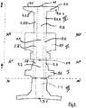
- intermediate panels (2.3; 2.3 ') laterally extend the lateral panels (2.2; 2.2') over all or part of their length and are adapted to flex along a fold line oriented along a longitudinal axis ( y, y ') and front panels (2.4; 2.4') laterally extend the intermediate panels (2.3; 2.3 ') over all or a portion of their length and are adapted to flex along a fold line oriented along a longitudinal axis ( y, y ').
- the additional intermediate panels (2.5) and (2.5 ') can be arranged between the front panels (2.4; 2.4') and the intermediate panels (2.3; 2.3 ').
- the reinforced splint can also be presented flat in the form of a kit.
- the kit for the reinforced splint according to the invention may comprise one or two reinforcements placed respectively in the extension of part I protecting the lower part of the limb and / or part II protecting the upper part of the limb. member.
- the inner lower reinforcement (III) is adapted to fold at 180 ° and to lodge inside the part I once its different parts are folded to form a channel.
- the outer lower reinforcement (III ') is adapted to fold back to 180 ° and insert the part I once its different parts are folded to form a channel.
- the inner upper reinforcement (IV) is adapted to fold at 180 ° and to lodge inside the part II once its different parts are folded to form a channel.
- the outer upper reinforcement (IV ') is adapted to fold back to 180 ° and insert the part II once its different parts are folded to form a channel.
- the establishment of the lower inner reinforcement (III) is effected by tilting at 180 ° along the axis (x, x ') of the part III thus formed so that it comes to be housed inside the L formed in step a), the central part (3.3) covering the sole (1.2), the horizontal branches of the brackets (3.2.2) and (3.2.2 ') superimposed on the inside of the flanks respectively (1.4) and (1.4 ') and the vertical branches of the brackets (3.2.1) and (3.2.1') superimposed inside the side panels respectively (2.2) and (2.2 ').
- the splint is provided with an external lower reinforcement (III ') its implementation is effected by tilting at 180 ° along the axis (x, x') of the outer lower reinforcement (III ') so formed so that it comes to insert the L formed in step a), the central part (3.3 ') being placed under the sole (1.2), the horizontal branches of the brackets (3.2.2) and (3.2.2') superimposed on the outside of the flanks respectively (1.4) and (1.4 ') and the vertical branches of the brackets (3.2.1) and (3.2.1') superimposed on the outside of the side panels respectively (2.2) and (2.2 ').
- the splint is provided with an inner upper reinforcement (IV) it is mounted similarly to the lower inner reinforcement (III) these two reinforcements being of generally identical design.
- junction between the part (I) and the part (II), at an angle between 45 ° and 135 ° relative to each other may take different forms according to the invention.
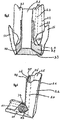
- the ends of the lateral panels (2.2) and (2.2 ') located at the joint come after folding in superposition of the end of the flanks (1.4) and (1.4'). They can be assembled by those skilled in the art using any known means of it, such as glues, staples, etc. It can also be envisaged among the many possible embodiments to reduce the end of the flanks (1.4) and (1.4 ') to each provide a tongue or any other means locking described above cooperating with another locking means made at the end of the side panels (2.2) and (2.2 '). According to another embodiment, the flanks (1.4) and (1.4 ') are not reduced and the locking means of each lateral panel then cooperates with a locking means placed opposite the junction of the side panels ( 2.2) and (2.2 ') and the posterior stem.
- the junction (1.5; 1.5 ') between Part I and Part II of the splint according to the invention can also be produced in the form of a bellows.
- the proposed invention also covers a similar bellows made on the side panels (2.2) and (2.2 ').
- a kit characterized in that a fold line is formed on each side (1.4; 1.4 ') extending diagonally respectively from the junction between the sole (1.2 ), the rod (2.1) and each said flank (1.4) and (1.4 ') to the opposite edge of said flank forming a bisector at the angle formed by the line delimiting the sole (1.2) of said flank and the fold line (x ", x '").
- junction triangles (1.5) and (1.5 ') are placed overlapping triangles complementary junctions (1.6) and (1.6'). Folding can be completed by a glue point, or any other means of equivalent fixation, applied between the triangles of junctions (1.5) and (1.5 ') and the complementary triangles of junctions (1.6) and (1.6').
- a fold line is formed on the side panels (2.2) and (2.2 ') extending diagonally respectively from the junction between the sole (1.2), the rod (2.1) and each said side panel (2.2) and (2.2 ') to the opposite edge of said side panel forming a bisector at the angle formed by the line delimiting the sole ( 1.2) of said side panel and the fold line (x ", x '").
Landscapes
- Health & Medical Sciences (AREA)
- Nursing (AREA)
- Orthopedic Medicine & Surgery (AREA)
- Engineering & Computer Science (AREA)
- Biomedical Technology (AREA)
- Heart & Thoracic Surgery (AREA)
- Vascular Medicine (AREA)
- Life Sciences & Earth Sciences (AREA)
- Animal Behavior & Ethology (AREA)
- General Health & Medical Sciences (AREA)
- Public Health (AREA)
- Veterinary Medicine (AREA)
- Orthopedics, Nursing, And Contraception (AREA)
Applications Claiming Priority (1)
| Application Number | Priority Date | Filing Date | Title |
|---|---|---|---|
| FR1670132A FR3049189B1 (fr) | 2016-03-24 | 2016-03-24 | Attelle enveloppante |
Publications (2)
| Publication Number | Publication Date |
|---|---|
| EP3222256A1 true EP3222256A1 (de) | 2017-09-27 |
| EP3222256B1 EP3222256B1 (de) | 2019-02-20 |
Family
ID=57681667
Family Applications (1)
| Application Number | Title | Priority Date | Filing Date |
|---|---|---|---|
| EP17162425.7A Not-in-force EP3222256B1 (de) | 2016-03-24 | 2017-03-22 | Umhüllende schiene |
Country Status (2)
| Country | Link |
|---|---|
| EP (1) | EP3222256B1 (de) |
| FR (1) | FR3049189B1 (de) |
Cited By (2)
| Publication number | Priority date | Publication date | Assignee | Title |
|---|---|---|---|---|
| CN109350060A (zh) * | 2018-10-17 | 2019-02-19 | 四川大学华西医院 | 一种核磁共振踝关节线圈装置 |
| US20230122424A1 (en) * | 2018-07-27 | 2023-04-20 | Leg Defender, Llc | Non-water-activated cast |
Citations (9)
| Publication number | Priority date | Publication date | Assignee | Title |
|---|---|---|---|---|
| US2700383A (en) | 1951-11-15 | 1955-01-25 | Moodie Virginia Boyle | Limb splint |
| US3232289A (en) * | 1963-03-22 | 1966-02-01 | Charles E Zimmerman | Temporary splint |
| US3496934A (en) | 1967-12-04 | 1970-02-24 | Chester S Anderson | Disposable immobilizing splint |
| US3624745A (en) | 1970-01-28 | 1971-11-30 | Don Bowers | Disposable splint |
| EP0004204A2 (de) * | 1978-03-14 | 1979-09-19 | Eric Gozna | Schiene und Streckverband |
| US4383526A (en) * | 1981-05-06 | 1983-05-17 | Seymour Robins | Disposable traction splint |
| FR2530946A3 (fr) * | 1982-07-28 | 1984-02-03 | Pepin Martine | Attelle orthopedique |
| EP0359635A1 (de) * | 1988-09-08 | 1990-03-21 | SOCIETE D'ETUDES ET DE RECHERCHES CREATIVITY Société Civile | Gelenkige Stabilisierungsvorrichtung |
| RU2150918C1 (ru) | 1998-05-15 | 2000-06-20 | ЗАО "НПП Экомедсервис" | Шина для транспортной иммобилизации травмированного при чрезвычайных ситуациях и дорожно-транспортных происшествиях человека |
-
2016
- 2016-03-24 FR FR1670132A patent/FR3049189B1/fr not_active Expired - Fee Related
-
2017
- 2017-03-22 EP EP17162425.7A patent/EP3222256B1/de not_active Not-in-force
Patent Citations (9)
| Publication number | Priority date | Publication date | Assignee | Title |
|---|---|---|---|---|
| US2700383A (en) | 1951-11-15 | 1955-01-25 | Moodie Virginia Boyle | Limb splint |
| US3232289A (en) * | 1963-03-22 | 1966-02-01 | Charles E Zimmerman | Temporary splint |
| US3496934A (en) | 1967-12-04 | 1970-02-24 | Chester S Anderson | Disposable immobilizing splint |
| US3624745A (en) | 1970-01-28 | 1971-11-30 | Don Bowers | Disposable splint |
| EP0004204A2 (de) * | 1978-03-14 | 1979-09-19 | Eric Gozna | Schiene und Streckverband |
| US4383526A (en) * | 1981-05-06 | 1983-05-17 | Seymour Robins | Disposable traction splint |
| FR2530946A3 (fr) * | 1982-07-28 | 1984-02-03 | Pepin Martine | Attelle orthopedique |
| EP0359635A1 (de) * | 1988-09-08 | 1990-03-21 | SOCIETE D'ETUDES ET DE RECHERCHES CREATIVITY Société Civile | Gelenkige Stabilisierungsvorrichtung |
| RU2150918C1 (ru) | 1998-05-15 | 2000-06-20 | ЗАО "НПП Экомедсервис" | Шина для транспортной иммобилизации травмированного при чрезвычайных ситуациях и дорожно-транспортных происшествиях человека |
Cited By (4)
| Publication number | Priority date | Publication date | Assignee | Title |
|---|---|---|---|---|
| US20230122424A1 (en) * | 2018-07-27 | 2023-04-20 | Leg Defender, Llc | Non-water-activated cast |
| US12213901B2 (en) * | 2018-07-27 | 2025-02-04 | Leg Defender, Llc | Non-water-activated cast |
| CN109350060A (zh) * | 2018-10-17 | 2019-02-19 | 四川大学华西医院 | 一种核磁共振踝关节线圈装置 |
| CN109350060B (zh) * | 2018-10-17 | 2023-12-05 | 四川大学华西医院 | 一种核磁共振踝关节线圈装置 |
Also Published As
| Publication number | Publication date |
|---|---|
| EP3222256B1 (de) | 2019-02-20 |
| FR3049189B1 (fr) | 2018-04-20 |
| FR3049189A1 (fr) | 2017-09-29 |
Similar Documents
| Publication | Publication Date | Title |
|---|---|---|
| EP0359635B1 (de) | Gelenkige Stabilisierungsvorrichtung | |
| CH654478A5 (fr) | Panneau pour la confection d'articles de maintien de la tete ou de membres de l'homme ou des animaux. | |
| EP2544637B1 (de) | Orthopädische vorrichtung zur mechanischen behandlung von hallux valgus | |
| EP1191912A1 (de) | Elastische hülse mit einen viskoelastischen polster zum schutz oder pflege der finger oder zehen | |
| EP0098983A2 (de) | Windel | |
| CA2166481A1 (fr) | Article d'hygiene absorbant jetable | |
| EP0732910A1 (de) | Wegwerfbarer absorbierender hygieneartikel mit einer eine stuhlaufnehmenden öffnung aufweisenden oberflächenlage | |
| EP3222256B1 (de) | Umhüllende schiene | |
| NO170258B (no) | Anordning ved engangsbleie | |
| NO138270B (no) | Festeanordning for engangsbleier | |
| MXPA00003402A (es) | Articulo absorbente. | |
| FR2648344A1 (fr) | Couche-culotte a ceinture elastique | |
| EP3294234B1 (de) | Vorrichtung zur unterstützung und/oder zum schutz von fingern oder zehen | |
| EP2134264B1 (de) | Vorrichtung für aktiven schutz der inzisionsränder | |
| US8257290B2 (en) | Temporary splint assembly with semi-rigid wrap around supports in combination with intermediately positioned joint cast | |
| FR2572649A1 (fr) | Garniture absorbante pour incontinents legers | |
| FR2654614A1 (fr) | Appareil destine a immobiliser un membre, a base de materiau cellulosique. | |
| EP0625345B1 (de) | Eine Monatsbinde, die vor der Anwendung zu einem Umschlag gefaltet ist | |
| WO2013001210A1 (fr) | Pansement pour recouvrir une partie saillante | |
| FR2807939A1 (fr) | Couche-culotte a pattes d'attache laterales du type autoagrippant | |
| FR2990344A1 (fr) | Attelle de poignet, procede de configuration d'une telle attelle et procede de pose d'une telle attelle | |
| FR2867969A1 (fr) | Dispositif de soutien ou de maintien pour le corps humain ou animal et son procede d'application | |
| FR2580591A1 (fr) | Poignee d'emballage | |
| FR2771627A1 (fr) | Bande adhesive et elastique pour la contention de la cheville ou du tendon d'achille et ensemble de contention comportant une telle bande | |
| EP2455433A1 (de) | Verstärkungsklebeband |
Legal Events
| Date | Code | Title | Description |
|---|---|---|---|
| PUAI | Public reference made under article 153(3) epc to a published international application that has entered the european phase |
Free format text: ORIGINAL CODE: 0009012 |
|
| STAA | Information on the status of an ep patent application or granted ep patent |
Free format text: STATUS: THE APPLICATION HAS BEEN PUBLISHED |
|
| AK | Designated contracting states |
Kind code of ref document: A1 Designated state(s): AL AT BE BG CH CY CZ DE DK EE ES FI FR GB GR HR HU IE IS IT LI LT LU LV MC MK MT NL NO PL PT RO RS SE SI SK SM TR |
|
| AX | Request for extension of the european patent |
Extension state: BA ME |
|
| STAA | Information on the status of an ep patent application or granted ep patent |
Free format text: STATUS: REQUEST FOR EXAMINATION WAS MADE |
|
| 17P | Request for examination filed |
Effective date: 20180327 |
|
| RBV | Designated contracting states (corrected) |
Designated state(s): AL AT BE BG CH CY CZ DE DK EE ES FI FR GB GR HR HU IE IS IT LI LT LU LV MC MK MT NL NO PL PT RO RS SE SI SK SM TR |
|
| GRAP | Despatch of communication of intention to grant a patent |
Free format text: ORIGINAL CODE: EPIDOSNIGR1 |
|
| STAA | Information on the status of an ep patent application or granted ep patent |
Free format text: STATUS: GRANT OF PATENT IS INTENDED |
|
| RIC1 | Information provided on ipc code assigned before grant |
Ipc: A61F 5/058 20060101AFI20180803BHEP |
|
| INTG | Intention to grant announced |
Effective date: 20180907 |
|
| GRAS | Grant fee paid |
Free format text: ORIGINAL CODE: EPIDOSNIGR3 |
|
| GRAA | (expected) grant |
Free format text: ORIGINAL CODE: 0009210 |
|
| STAA | Information on the status of an ep patent application or granted ep patent |
Free format text: STATUS: THE PATENT HAS BEEN GRANTED |
|
| AK | Designated contracting states |
Kind code of ref document: B1 Designated state(s): AL AT BE BG CH CY CZ DE DK EE ES FI FR GB GR HR HU IE IS IT LI LT LU LV MC MK MT NL NO PL PT RO RS SE SI SK SM TR |
|
| REG | Reference to a national code |
Ref country code: GB Ref legal event code: FG4D Free format text: NOT ENGLISH |
|
| REG | Reference to a national code |
Ref country code: CH Ref legal event code: EP |
|
| REG | Reference to a national code |
Ref country code: DE Ref legal event code: R096 Ref document number: 602017002164 Country of ref document: DE |
|
| REG | Reference to a national code |
Ref country code: AT Ref legal event code: REF Ref document number: 1097211 Country of ref document: AT Kind code of ref document: T Effective date: 20190315 |
|
| REG | Reference to a national code |
Ref country code: IE Ref legal event code: FG4D Free format text: LANGUAGE OF EP DOCUMENT: FRENCH |
|
| REG | Reference to a national code |
Ref country code: LT Ref legal event code: MG4D Ref country code: NL Ref legal event code: MP Effective date: 20190220 |
|
| PG25 | Lapsed in a contracting state [announced via postgrant information from national office to epo] |
Ref country code: FI Free format text: LAPSE BECAUSE OF FAILURE TO SUBMIT A TRANSLATION OF THE DESCRIPTION OR TO PAY THE FEE WITHIN THE PRESCRIBED TIME-LIMIT Effective date: 20190220 Ref country code: NO Free format text: LAPSE BECAUSE OF FAILURE TO SUBMIT A TRANSLATION OF THE DESCRIPTION OR TO PAY THE FEE WITHIN THE PRESCRIBED TIME-LIMIT Effective date: 20190520 Ref country code: PT Free format text: LAPSE BECAUSE OF FAILURE TO SUBMIT A TRANSLATION OF THE DESCRIPTION OR TO PAY THE FEE WITHIN THE PRESCRIBED TIME-LIMIT Effective date: 20190620 Ref country code: SE Free format text: LAPSE BECAUSE OF FAILURE TO SUBMIT A TRANSLATION OF THE DESCRIPTION OR TO PAY THE FEE WITHIN THE PRESCRIBED TIME-LIMIT Effective date: 20190220 Ref country code: LT Free format text: LAPSE BECAUSE OF FAILURE TO SUBMIT A TRANSLATION OF THE DESCRIPTION OR TO PAY THE FEE WITHIN THE PRESCRIBED TIME-LIMIT Effective date: 20190220 Ref country code: ES Free format text: LAPSE BECAUSE OF FAILURE TO SUBMIT A TRANSLATION OF THE DESCRIPTION OR TO PAY THE FEE WITHIN THE PRESCRIBED TIME-LIMIT Effective date: 20190220 |
|
| PG25 | Lapsed in a contracting state [announced via postgrant information from national office to epo] |
Ref country code: RS Free format text: LAPSE BECAUSE OF FAILURE TO SUBMIT A TRANSLATION OF THE DESCRIPTION OR TO PAY THE FEE WITHIN THE PRESCRIBED TIME-LIMIT Effective date: 20190220 Ref country code: GR Free format text: LAPSE BECAUSE OF FAILURE TO SUBMIT A TRANSLATION OF THE DESCRIPTION OR TO PAY THE FEE WITHIN THE PRESCRIBED TIME-LIMIT Effective date: 20190521 Ref country code: HR Free format text: LAPSE BECAUSE OF FAILURE TO SUBMIT A TRANSLATION OF THE DESCRIPTION OR TO PAY THE FEE WITHIN THE PRESCRIBED TIME-LIMIT Effective date: 20190220 Ref country code: NL Free format text: LAPSE BECAUSE OF FAILURE TO SUBMIT A TRANSLATION OF THE DESCRIPTION OR TO PAY THE FEE WITHIN THE PRESCRIBED TIME-LIMIT Effective date: 20190220 Ref country code: LV Free format text: LAPSE BECAUSE OF FAILURE TO SUBMIT A TRANSLATION OF THE DESCRIPTION OR TO PAY THE FEE WITHIN THE PRESCRIBED TIME-LIMIT Effective date: 20190220 Ref country code: BG Free format text: LAPSE BECAUSE OF FAILURE TO SUBMIT A TRANSLATION OF THE DESCRIPTION OR TO PAY THE FEE WITHIN THE PRESCRIBED TIME-LIMIT Effective date: 20190520 Ref country code: IS Free format text: LAPSE BECAUSE OF FAILURE TO SUBMIT A TRANSLATION OF THE DESCRIPTION OR TO PAY THE FEE WITHIN THE PRESCRIBED TIME-LIMIT Effective date: 20190620 |
|
| REG | Reference to a national code |
Ref country code: AT Ref legal event code: MK05 Ref document number: 1097211 Country of ref document: AT Kind code of ref document: T Effective date: 20190220 |
|
| REG | Reference to a national code |
Ref country code: DE Ref legal event code: R119 Ref document number: 602017002164 Country of ref document: DE |
|
| PG25 | Lapsed in a contracting state [announced via postgrant information from national office to epo] |
Ref country code: SK Free format text: LAPSE BECAUSE OF FAILURE TO SUBMIT A TRANSLATION OF THE DESCRIPTION OR TO PAY THE FEE WITHIN THE PRESCRIBED TIME-LIMIT Effective date: 20190220 Ref country code: RO Free format text: LAPSE BECAUSE OF FAILURE TO SUBMIT A TRANSLATION OF THE DESCRIPTION OR TO PAY THE FEE WITHIN THE PRESCRIBED TIME-LIMIT Effective date: 20190220 Ref country code: DK Free format text: LAPSE BECAUSE OF FAILURE TO SUBMIT A TRANSLATION OF THE DESCRIPTION OR TO PAY THE FEE WITHIN THE PRESCRIBED TIME-LIMIT Effective date: 20190220 Ref country code: EE Free format text: LAPSE BECAUSE OF FAILURE TO SUBMIT A TRANSLATION OF THE DESCRIPTION OR TO PAY THE FEE WITHIN THE PRESCRIBED TIME-LIMIT Effective date: 20190220 Ref country code: IT Free format text: LAPSE BECAUSE OF FAILURE TO SUBMIT A TRANSLATION OF THE DESCRIPTION OR TO PAY THE FEE WITHIN THE PRESCRIBED TIME-LIMIT Effective date: 20190220 Ref country code: AL Free format text: LAPSE BECAUSE OF FAILURE TO SUBMIT A TRANSLATION OF THE DESCRIPTION OR TO PAY THE FEE WITHIN THE PRESCRIBED TIME-LIMIT Effective date: 20190220 Ref country code: CZ Free format text: LAPSE BECAUSE OF FAILURE TO SUBMIT A TRANSLATION OF THE DESCRIPTION OR TO PAY THE FEE WITHIN THE PRESCRIBED TIME-LIMIT Effective date: 20190220 |
|
| PG25 | Lapsed in a contracting state [announced via postgrant information from national office to epo] |
Ref country code: PL Free format text: LAPSE BECAUSE OF FAILURE TO SUBMIT A TRANSLATION OF THE DESCRIPTION OR TO PAY THE FEE WITHIN THE PRESCRIBED TIME-LIMIT Effective date: 20190220 Ref country code: SM Free format text: LAPSE BECAUSE OF FAILURE TO SUBMIT A TRANSLATION OF THE DESCRIPTION OR TO PAY THE FEE WITHIN THE PRESCRIBED TIME-LIMIT Effective date: 20190220 Ref country code: LU Free format text: LAPSE BECAUSE OF NON-PAYMENT OF DUE FEES Effective date: 20190322 |
|
| REG | Reference to a national code |
Ref country code: BE Ref legal event code: MM Effective date: 20190331 |
|
| PLBE | No opposition filed within time limit |
Free format text: ORIGINAL CODE: 0009261 |
|
| STAA | Information on the status of an ep patent application or granted ep patent |
Free format text: STATUS: NO OPPOSITION FILED WITHIN TIME LIMIT |
|
| PG25 | Lapsed in a contracting state [announced via postgrant information from national office to epo] |
Ref country code: AT Free format text: LAPSE BECAUSE OF FAILURE TO SUBMIT A TRANSLATION OF THE DESCRIPTION OR TO PAY THE FEE WITHIN THE PRESCRIBED TIME-LIMIT Effective date: 20190220 Ref country code: MC Free format text: LAPSE BECAUSE OF FAILURE TO SUBMIT A TRANSLATION OF THE DESCRIPTION OR TO PAY THE FEE WITHIN THE PRESCRIBED TIME-LIMIT Effective date: 20190220 |
|
| 26N | No opposition filed |
Effective date: 20191121 |
|
| PG25 | Lapsed in a contracting state [announced via postgrant information from national office to epo] |
Ref country code: DE Free format text: LAPSE BECAUSE OF NON-PAYMENT OF DUE FEES Effective date: 20191001 Ref country code: IE Free format text: LAPSE BECAUSE OF NON-PAYMENT OF DUE FEES Effective date: 20190322 |
|
| PG25 | Lapsed in a contracting state [announced via postgrant information from national office to epo] |
Ref country code: FR Free format text: LAPSE BECAUSE OF NON-PAYMENT OF DUE FEES Effective date: 20190420 Ref country code: BE Free format text: LAPSE BECAUSE OF NON-PAYMENT OF DUE FEES Effective date: 20190331 Ref country code: SI Free format text: LAPSE BECAUSE OF FAILURE TO SUBMIT A TRANSLATION OF THE DESCRIPTION OR TO PAY THE FEE WITHIN THE PRESCRIBED TIME-LIMIT Effective date: 20190220 |
|
| PG25 | Lapsed in a contracting state [announced via postgrant information from national office to epo] |
Ref country code: TR Free format text: LAPSE BECAUSE OF FAILURE TO SUBMIT A TRANSLATION OF THE DESCRIPTION OR TO PAY THE FEE WITHIN THE PRESCRIBED TIME-LIMIT Effective date: 20190220 |
|
| PG25 | Lapsed in a contracting state [announced via postgrant information from national office to epo] |
Ref country code: MT Free format text: LAPSE BECAUSE OF FAILURE TO SUBMIT A TRANSLATION OF THE DESCRIPTION OR TO PAY THE FEE WITHIN THE PRESCRIBED TIME-LIMIT Effective date: 20190220 |
|
| REG | Reference to a national code |
Ref country code: CH Ref legal event code: PL |
|
| PG25 | Lapsed in a contracting state [announced via postgrant information from national office to epo] |
Ref country code: LI Free format text: LAPSE BECAUSE OF NON-PAYMENT OF DUE FEES Effective date: 20200331 Ref country code: CH Free format text: LAPSE BECAUSE OF NON-PAYMENT OF DUE FEES Effective date: 20200331 |
|
| PG25 | Lapsed in a contracting state [announced via postgrant information from national office to epo] |
Ref country code: CY Free format text: LAPSE BECAUSE OF FAILURE TO SUBMIT A TRANSLATION OF THE DESCRIPTION OR TO PAY THE FEE WITHIN THE PRESCRIBED TIME-LIMIT Effective date: 20190220 |
|
| PG25 | Lapsed in a contracting state [announced via postgrant information from national office to epo] |
Ref country code: HU Free format text: LAPSE BECAUSE OF FAILURE TO SUBMIT A TRANSLATION OF THE DESCRIPTION OR TO PAY THE FEE WITHIN THE PRESCRIBED TIME-LIMIT; INVALID AB INITIO Effective date: 20170322 |
|
| GBPC | Gb: european patent ceased through non-payment of renewal fee |
Effective date: 20210322 |
|
| PG25 | Lapsed in a contracting state [announced via postgrant information from national office to epo] |
Ref country code: GB Free format text: LAPSE BECAUSE OF NON-PAYMENT OF DUE FEES Effective date: 20210322 |
|
| PG25 | Lapsed in a contracting state [announced via postgrant information from national office to epo] |
Ref country code: MK Free format text: LAPSE BECAUSE OF FAILURE TO SUBMIT A TRANSLATION OF THE DESCRIPTION OR TO PAY THE FEE WITHIN THE PRESCRIBED TIME-LIMIT Effective date: 20190220 |