EP3222409B1 - Procédé de mise en forme tridimensionnelle - Google Patents
Procédé de mise en forme tridimensionnelle Download PDFInfo
- Publication number
- EP3222409B1 EP3222409B1 EP16200646.4A EP16200646A EP3222409B1 EP 3222409 B1 EP3222409 B1 EP 3222409B1 EP 16200646 A EP16200646 A EP 16200646A EP 3222409 B1 EP3222409 B1 EP 3222409B1
- Authority
- EP
- European Patent Office
- Prior art keywords
- multilayers
- coordinates
- cross sections
- thickness
- shaping method
- Prior art date
- Legal status (The legal status is an assumption and is not a legal conclusion. Google has not performed a legal analysis and makes no representation as to the accuracy of the status listed.)
- Active
Links
Images


Classifications
-
- B—PERFORMING OPERATIONS; TRANSPORTING
- B29—WORKING OF PLASTICS; WORKING OF SUBSTANCES IN A PLASTIC STATE IN GENERAL
- B29C—SHAPING OR JOINING OF PLASTICS; SHAPING OF MATERIAL IN A PLASTIC STATE, NOT OTHERWISE PROVIDED FOR; AFTER-TREATMENT OF THE SHAPED PRODUCTS, e.g. REPAIRING
- B29C64/00—Additive manufacturing, i.e. manufacturing of three-dimensional [3D] objects by additive deposition, additive agglomeration or additive layering, e.g. by 3D printing, stereolithography or selective laser sintering
- B29C64/10—Processes of additive manufacturing
- B29C64/141—Processes of additive manufacturing using only solid materials
- B29C64/153—Processes of additive manufacturing using only solid materials using layers of powder being selectively joined, e.g. by selective laser sintering or melting
-
- B—PERFORMING OPERATIONS; TRANSPORTING
- B22—CASTING; POWDER METALLURGY
- B22F—WORKING METALLIC POWDER; MANUFACTURE OF ARTICLES FROM METALLIC POWDER; MAKING METALLIC POWDER; APPARATUS OR DEVICES SPECIALLY ADAPTED FOR METALLIC POWDER
- B22F10/00—Additive manufacturing of workpieces or articles from metallic powder
-
- B—PERFORMING OPERATIONS; TRANSPORTING
- B22—CASTING; POWDER METALLURGY
- B22F—WORKING METALLIC POWDER; MANUFACTURE OF ARTICLES FROM METALLIC POWDER; MAKING METALLIC POWDER; APPARATUS OR DEVICES SPECIALLY ADAPTED FOR METALLIC POWDER
- B22F10/00—Additive manufacturing of workpieces or articles from metallic powder
- B22F10/20—Direct sintering or melting
- B22F10/28—Powder bed fusion, e.g. selective laser melting [SLM] or electron beam melting [EBM]
-
- B—PERFORMING OPERATIONS; TRANSPORTING
- B22—CASTING; POWDER METALLURGY
- B22F—WORKING METALLIC POWDER; MANUFACTURE OF ARTICLES FROM METALLIC POWDER; MAKING METALLIC POWDER; APPARATUS OR DEVICES SPECIALLY ADAPTED FOR METALLIC POWDER
- B22F10/00—Additive manufacturing of workpieces or articles from metallic powder
- B22F10/30—Process control
- B22F10/36—Process control of energy beam parameters
-
- B—PERFORMING OPERATIONS; TRANSPORTING
- B22—CASTING; POWDER METALLURGY
- B22F—WORKING METALLIC POWDER; MANUFACTURE OF ARTICLES FROM METALLIC POWDER; MAKING METALLIC POWDER; APPARATUS OR DEVICES SPECIALLY ADAPTED FOR METALLIC POWDER
- B22F10/00—Additive manufacturing of workpieces or articles from metallic powder
- B22F10/80—Data acquisition or data processing
-
- B—PERFORMING OPERATIONS; TRANSPORTING
- B29—WORKING OF PLASTICS; WORKING OF SUBSTANCES IN A PLASTIC STATE IN GENERAL
- B29C—SHAPING OR JOINING OF PLASTICS; SHAPING OF MATERIAL IN A PLASTIC STATE, NOT OTHERWISE PROVIDED FOR; AFTER-TREATMENT OF THE SHAPED PRODUCTS, e.g. REPAIRING
- B29C64/00—Additive manufacturing, i.e. manufacturing of three-dimensional [3D] objects by additive deposition, additive agglomeration or additive layering, e.g. by 3D printing, stereolithography or selective laser sintering
- B29C64/30—Auxiliary operations or equipment
- B29C64/386—Data acquisition or data processing for additive manufacturing
- B29C64/393—Data acquisition or data processing for additive manufacturing for controlling or regulating additive manufacturing processes
-
- B—PERFORMING OPERATIONS; TRANSPORTING
- B33—ADDITIVE MANUFACTURING TECHNOLOGY
- B33Y—ADDITIVE MANUFACTURING, i.e. MANUFACTURING OF THREE-DIMENSIONAL [3D] OBJECTS BY ADDITIVE DEPOSITION, ADDITIVE AGGLOMERATION OR ADDITIVE LAYERING, e.g. BY 3D PRINTING, STEREOLITHOGRAPHY OR SELECTIVE LASER SINTERING
- B33Y10/00—Processes of additive manufacturing
-
- B—PERFORMING OPERATIONS; TRANSPORTING
- B33—ADDITIVE MANUFACTURING TECHNOLOGY
- B33Y—ADDITIVE MANUFACTURING, i.e. MANUFACTURING OF THREE-DIMENSIONAL [3D] OBJECTS BY ADDITIVE DEPOSITION, ADDITIVE AGGLOMERATION OR ADDITIVE LAYERING, e.g. BY 3D PRINTING, STEREOLITHOGRAPHY OR SELECTIVE LASER SINTERING
- B33Y50/00—Data acquisition or data processing for additive manufacturing
- B33Y50/02—Data acquisition or data processing for additive manufacturing for controlling or regulating additive manufacturing processes
-
- B—PERFORMING OPERATIONS; TRANSPORTING
- B29—WORKING OF PLASTICS; WORKING OF SUBSTANCES IN A PLASTIC STATE IN GENERAL
- B29K—INDEXING SCHEME ASSOCIATED WITH SUBCLASSES B29B, B29C OR B29D, RELATING TO MOULDING MATERIALS OR TO MATERIALS FOR MOULDS, REINFORCEMENTS, FILLERS OR PREFORMED PARTS, e.g. INSERTS
- B29K2105/00—Condition, form or state of moulded material or of the material to be shaped
- B29K2105/25—Solid
- B29K2105/251—Particles, powder or granules
-
- Y—GENERAL TAGGING OF NEW TECHNOLOGICAL DEVELOPMENTS; GENERAL TAGGING OF CROSS-SECTIONAL TECHNOLOGIES SPANNING OVER SEVERAL SECTIONS OF THE IPC; TECHNICAL SUBJECTS COVERED BY FORMER USPC CROSS-REFERENCE ART COLLECTIONS [XRACs] AND DIGESTS
- Y02—TECHNOLOGIES OR APPLICATIONS FOR MITIGATION OR ADAPTATION AGAINST CLIMATE CHANGE
- Y02P—CLIMATE CHANGE MITIGATION TECHNOLOGIES IN THE PRODUCTION OR PROCESSING OF GOODS
- Y02P10/00—Technologies related to metal processing
- Y02P10/25—Process efficiency
Definitions
- the present invention relates to a method of manufacturing a three-dimensional shaped article in which when a step of forming a powder layer and a sintering step using a laser beam or an electron beam on the powder layer are repeated, the thickness of each multilayer unit can be selected.
- each multilayer unit is constant in most cases, as for example in document US 6084980 .
- Patent Document 1 Although consideration is given to the optimization of the thickness of the outermost surface layer in three-dimensional shaping, the thickness is not changed for each multilayer unit.
- Patent Document 2 discloses that, when in a multilayer operation in a predetermined stage, a convex portion exceeding the thickness of multilayers is detected, the thickness of multilayers in the subsequent stage is set to exceed the height of the convex portion.
- the thickness is not selected based on unified criteria corresponding to the overall shape of a shaped object.
- each multilayer cross section when the shape of each multilayer cross section is significantly varied along the height direction, the thickness of each multilayer unit is decreased such that the original shape of the shaped object can be accurately realized whereas when only a slight variation in the thickness along the up/down direction is produced, even if the thickness of each multilayer unit is set larger, the original shape of the shaped object does not necessarily become inaccurate.
- An object of the present invention is to provide, in a three-dimensional shaping method, a configuration in which the thickness of each multilayer unit is appropriately set according to the degree of variation in the cross section of a shaped object in a horizontal direction along a height direction.
- the number of multilayers (N) in each of the divided regions is set according to a variation in the cross-sectional shape of each of the divided regions in the boundary in the horizontal direction, that is, the variation in the average distance from the center in the case of the basic configuration (1), the variation in the sum of the maximum widths in the lateral direction and the vertical direction in the Cartesian coordinates in the case of the basic configuration (2) and the variation in the maximum distance from the center position in the rotational coordinates in the case of the basic configuration (3), and the coordinates of the periphery of each of the cross sections based on the appropriate thickness and the number of multilayers (N) are set according to a variation in the surface in each multilayer unit in the horizontal direction, with the result that it is possible to realize the accurate shape of the shaped object.
- the basic configurations (1), (2) and (3) are common in that a plurality of divided regions 2 are set in the multilayer region 4 along the height region of the shaping.
- each of the divided regions 2 On both the upper and lower sides of each of the divided regions 2, the boundaries are always present, however, in each of the divided regions 2, as a larger variation is produced between the shape of the cross section 3 of the boundary on the upper side and the shape of the cross section 3 of the boundary on the lower side, a large state of variation conditions is produced in the outer periphery 6 along the length direction.
- the number of multilayers N is selected according to the variation conditions described above.
- the average distance of the cross section 3 is selected as a parameter
- the sum of the maximum width of the cross section 3 in the lateral direction and the maximum width thereof in the vertical direction is selected as a parameter
- the maximum distance from the center position 5 is selected as a parameter.
- These parameters are selected based on the fact that, in each of the equal-width divided regions 2, a larger difference of the each parameters is produced between the cross section 3 on the upper side and the cross section 3 on the lower side, a larger variation condition is produced among respective parameters in the multilayer cross sections 3 along the height direction.
- the center position 5 of each of the cross sections 3 and the average distance from the center position 5 to the outer periphery 6 are calculated, and for each of the equal-width divided regions 2, the absolute value d of a difference between the average distance of the respective cross sections 3 in the boundary on the upper side and the average distance of the respective cross sections 3 in the boundary on the lower side is calculated, and in the basic configuration (2), the Cartesian coordinates, that is, the (x, y) coordinates are adopted, and then in the respective cross sections 3 forming boundaries of both the upper and lower sides in the equal-width divided regions 2 of a model which is to be shaped, with a CAM or a computer controller, as shown in Figs.
- the sum of the maximum widths of the respective cross sections 3 in the lateral direction and the maximum widths thereof in the vertical direction are calculated and, for each of the equal-width divided regions 2, the absolute value d of a difference between the sum of the respective cross sections 3 in the boundary on the upper side and the sum of the respective cross sections 3 in the boundary on the lower side is calculated, and then in the basic configuration (3), the rotational coordinates, that is, the (r, ⁇ ) coordinates are adopted, and then in the respective cross sections 3 forming the boundaries of both the upper and lower sides in the equal-width divided regions 2 of a model which is to be shaped, with a CAM or a computer controller, as shown in Figs.
- the center position 5 of each of the cross sections 3 and the maximum distance from the center position 5 to the outer periphery 6 are calculated and, for each of the equal-width divided regions 2, the absolute value d of a difference between the maximum distance of the respective cross sections 3 in the boundary on the upper side and the maximum distance of the respective cross sections 3 in the boundary on the lower side is calculated.
- the calculations of the parameters in the respective cross section 3 are realized with a CAM or a computer controller, when as in the basic configuration (1), the average distance from the center position 5 is selected as the parameter, the parameter can reflect the shape of the cross section 3 extremely accurately, whereas when as in the basic configuration (2), the maximum width in the lateral direction and the maximum width in the vertical direction are selected as the parameters and when as in the basic configuration (3), the maximum distance from the center position 5 is selected as the parameter, it is impossible to deny the fact that the basic configurations (2) and (3) are inferior to the basic configuration (1) in the accurate reflection of the shape of the cross section 3.
- the process 1 in the basic configuration (1) is suitable for a case where the shaping is previously realized according to the model of each shaped object 1.
- a size relationship between r l and r m is based on a criterion in which the cross section in the boundary on the upper side is common to the cross section in the boundary on the lower side, and this is because it is naturally assumed that the number h of coordinates in the cross section in the boundary on the upper side and the cross section in the boundary on the lower side in each of the equal-width divided regions is set such that the division which is so fine as not to reverse the size relationship between r l and r m in the cross section in the boundary on the upper side and the cross section in the boundary on the lower side can be performed.
- the minimum number of multilayers N 1 is set, this is because in some shaped objects 1, a region is present in which at a predetermined height and a predetermined width, the shape of the cross section 3 is not varied according to the height direction.
- the maximum value D is always present, and in this case, since the largest variation in the shape of the cross section 3 within the equal-width divided region 2 is produced, the maximum number of multilayers N 2 is set.
- the number of multilayers N reflecting the size relationship between the minimum value N 1 and the maximum value N 2 is selected, this selection is not particularly limited, and the order of the variations of the shape of the cross section 3 needs to reflect the order of the number of multilayers.
- each of the equal-width divided regions 2 according to the process 1 is further equally divided along the up/down direction into N regions, and then in the process 1 of the equally divided N cross sections 3, the coordinates of the outer periphery 6 corresponding to a model which is to be shaped are set.
- the setting of the coordinates of the outer periphery 6 can be realized by recording the shape of the model described above in the memory of the CAM and then the respective coordinates of the outer periphery regions 6 corresponding to the model described above in the cross section 3 by the further equal-width division of each of the equal-width divided regions 2 into the N regions can be calculated with the CAM.
- N 1 ⁇ d D N 1 + d D N 2
- N N 1 1 ⁇ d D ⁇ N 2 d D
- Example 1 is characterized in that the amount of laser beam or electron beam applied per unit area is adjusted according to the thickness of each of the multilayers.
- the degree of sintering is adjusted according to the function of each region as a matter of course.
- Example 1 in order to avoid such a disadvantage, the degree of sintering is adjusted according to the variation in the thickness, it is made possible to satisfy the requirement for the function in each region.
- Example 2 is characterized in that when the cross sections 3 of the respective multilayer units are located in the same position in a direction perpendicular to the height direction, as the thickness of each multilayer unit is increased, the amount of radiation applied per unit area is set larger.
- Example 2 consideration is given to such a condition, and as the thickness of each multilayer unit is increased, the amount of radiation applied per unit area is increased, with the result that it is made possible to realize a uniform degree of sintering.
- the present invention it is made possible to set the appropriate thickness of each multilayer unit according to the variation in the cross-sectional shape of the shaped object in the up/down direction, and the present invention can be utilized for all three-dimensional shaping.
Landscapes
- Engineering & Computer Science (AREA)
- Chemical & Material Sciences (AREA)
- Materials Engineering (AREA)
- Manufacturing & Machinery (AREA)
- Physics & Mathematics (AREA)
- Optics & Photonics (AREA)
- Mechanical Engineering (AREA)
- Automation & Control Theory (AREA)
- Plasma & Fusion (AREA)
- Powder Metallurgy (AREA)
Claims (17)
- Méthode de mise en forme tridimensionnelle dans laquelle une étape de formation d'une couche de poudre et une étape de frittage de la couche de poudre par application d'un faisceau laser mobile ou d'un faisceau d'électrons mobile sont répétées en alternance afin d'accomplir une opération multicouche au sein d'un récipient,
dans laquelle, par adoption de coordonnées cartésiennes, à savoir des coordonnées (x, y, z), la coordonnée z définissant une direction de hauteur, un modèle d'un objet (1) à mettre en forme est divisé en une pluralité de régions (2) d'épaisseur égale le long de la direction z, et dans laquelle un nombre N de multicouches (4) pour chaque région (2) divisée et une épaisseur de chaque multicouche (4) dans chaque région (2) divisée sont sélectionnés, dans laquelle la sélection du nombre N et de l'épaisseur de multicouches (4) comprend les étapes suivantes :1. un procédé de calcul en coordonnées (x, y) des éléments suivants :dans des sections transversales (3) respectives formant des frontières des deux côtés supérieur et inférieur dans les régions (2) divisées du modèle de l'objet (1) qui doit être mis en forme, à partir de chaque position de coordonnées (x1, y1) ... (xi, yi) ... (xh, yh) formant une périphérie externe (6) de chaque section transversale (3) et enregistrée dans une fabrication assistée par ordinateur (CAM) ou une commande par ordinateur, une position centrale (x0, y0) (5) de chacune des sections transversales (3) est calculée selon
 et concernant une distance moyenne r de la position centrale (x0, y0) (5) à chaque position de coordonnées (x1, y1) ... (xi, yi) ... (xh, yh) dans la périphérie externe (6), de calcul et d'enregistrement avec une mise en page assistée par ordinateur ou un contrôleur d'ordinateur de
 , et ensuite de calcul de
 de calcul, pour chacune des régions (2) divisées, d'une valeur absolue d d'une différence entre une distance moyenne des sections transversales (3) respectives dans la frontière sur le côté supérieur et une distance moyenne des sections transversales (3) respectives dans la frontière sur le côté inférieur ;2. un procédé pour, lorsque l'on part de l'hypothèse que d est 0, fixer un nombre minimal N1 de multicouches (4), détecter une valeur maximale D de d et fixer un nombre maximal N2 de multicouches (4) dans la région (2) divisée où la valeur maximale D est formée ;3. un procédé pour fixer un nombre n croissant au fur et à mesure que d augmente entre la valeur minimale N1 et la valeur maximale N2, et sélectionner un nombre N de multicouches (4) dans lequel N = [n], dans lequel [] est un symbole gaussien indiquant une unité d'un nombre entier ;4. un procédé pour fixer, lorsque dans chacune des régions (2) divisées dans l'étape 1 ci-dessus, une division d'épaisseur égale de la région (2) le long de la direction de hauteur est en outre accomplie avec le nombre N de multicouches (4) dans l'étape 3 ci-dessus, des coordonnées de la périphérie externe (6) correspondant au modèle de l'objet (1) dans l'étape 1 ci-dessus dans chacune des sections transversales (3) du nombre N ; et5. un procédé pour commander, en mise en forme réelle, la formation et le frittage de la couche de poudre sur la base du nombre N de multicouches (4) sélectionné dans l'étape 3 ci-dessus dans chacune des régions (2) divisées et le déplacement d'un outil de coupe dans lequel une position des coordonnées de la périphérie externe (6) fixées dans l'étape 4 ci-dessus est une position de coupe finale.
 - Méthode de mise en forme tridimensionnelle selon la revendication 1, dans laquelle, lorsque le nombre de multicouches (4) est N, une moyenne arithmétique entre la valeur minimale N1 et la valeur maximale N2 indiquée ci-dessous est adoptée.

- Méthode de mise en forme tridimensionnelle selon la revendication 1, dans laquelle, lorsque le nombre de multicouches (4) est N, une moyenne géométrique entre la valeur minimale N1 et la valeur maximale N2 indiquée ci-dessous est adoptée.
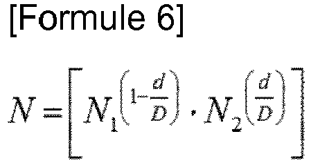
- Méthode de mise en forme tridimensionnelle selon les revendications 1 à 3,
dans laquelle, lorsque le nombre de multicouches (4) est N, une valeur moyenne de la moyenne arithmétique selon la revendication 2 et de la moyenne géométrique selon la revendication 3 est adoptée. - Méthode de mise en forme tridimensionnelle selon la revendication 1, dans laquelle, pour d dans chaque région de K régions (2) divisées, un ordre de d1 ≤ d2 ≤ ... ≤ di ≤ ... ≤ dk est détecté, et
ensuite, la formule 7 suivante reflétant un ordre de grandeur de d indiquée ci-dessous est adoptée.
- Méthode de mise en forme tridimensionnelle dans laquelle une étape de formation d'une couche de poudre et une étape de frittage de la couche de poudre par application d'un faisceau laser mobile ou d'un faisceau d'électrons mobile sont répétées en alternance afin d'accomplir une opération multicouche au sein d'un récipient,
dans laquelle, par adoption de coordonnées cartésiennes, à savoir des coordonnées (x, y, z), la coordonnée z définissant une direction de hauteur, un modèle d'un objet (1) à mettre en forme est divisé en une pluralité de régions (2) d'épaisseur égale le long de la direction z, et dans laquelle un nombre N de multicouches (4) pour chaque région (2) divisée et une épaisseur de chaque multicouche (4) dans chaque région (2) divisée sont sélectionnés, dans laquelle la sélection du nombre N et de l'épaisseur de multicouches (4) comprend les étapes suivantes :1. un procédé de calcul en coordonnées (x, y) des éléments suivants :dans des sections transversales (3) respectives formant des frontières des deux côtés supérieur et inférieur dans les régions (2) divisées du modèle de l'objet (1) qui doit être mis en forme, d'une somme de largeurs maximales des sections transversales (3) respectives dans une direction latérale et de largeurs maximales de celles-ci dans une direction verticale avec une fabrication assistée par ordinateur ou une commande par ordinateur etde calcul, pour chacune des régions (2) divisées, d'une valeur absolue d d'une différence entre une somme des sections transversales (3) respectives dans la frontière sur le côté supérieur et une somme des sections transversales (3) respectives dans la frontière sur le côté inférieur ;2. un procédé pour, lorsque l'on part de l'hypothèse que d est 0, fixer un nombre minimal N1 de multicouches (4), détecter une valeur maximale D de d et fixer un nombre maximal N2 de multicouches (4) dans la région (2) divisée où la valeur maximale D est formée ;3. un procédé pour fixer un nombre n croissant au fur et à mesure que d augmente entre la valeur minimale N1 et la valeur maximale N2, et sélectionner un nombre N de multicouches (4), dans lequel N = [n], dans lequel [] est un symbole gaussien indiquant une unité d'un nombre entier ;4. un procédé pour fixer, lorsque dans chacune des régions (2) divisées dans l'étape 1 ci-dessus, une division d'épaisseur égale de la région (2) le long de la direction de hauteur est en outre accomplie avec le nombre N de multicouches (4) dans l'étape 3 ci-dessus, des coordonnées de la périphérie externe (6) correspondant au modèle de l'objet (1) dans l'étape 1 ci-dessus dans chacune des sections transversales (3) du nombre N ; et5. un procédé pour commander, en mise en forme réelle, la formation et le frittage de la couche de poudre sur la base du nombre N de multicouches (4) sélectionné dans l'étape 3 ci-dessus dans chacune des régions (2) divisées et le déplacement d'un outil de coupe dans lequel une position des coordonnées de la périphérie externe (6) fixées dans l'étape 4 ci-dessus est une position de coupe finale. - Méthode de mise en forme tridimensionnelle selon la revendication 6, dans laquelle, lorsque le nombre de multicouches (4) est N, une moyenne arithmétique entre la valeur minimale N1 et la valeur maximale N2 indiquée ci-dessous est adoptée.

- Méthode de mise en forme tridimensionnelle selon la revendication 6, dans laquelle, lorsque le nombre de multicouches (4) est N, une moyenne géométrique entre la valeur minimale N1 et la valeur maximale N2 indiquée ci-dessous est adoptée.

- Méthode de mise en forme tridimensionnelle selon les revendications 6 à 8,
dans laquelle, lorsque le nombre de multicouches (4) est N, une valeur moyenne de la moyenne arithmétique selon la revendication 7 et de la moyenne géométrique selon la revendication 8 est adoptée. - Méthode de mise en forme tridimensionnelle selon la revendication 6, dans laquelle, pour d dans chaque région de K régions (2) divisées, un ordre de d1 ≤ d2 ≤ ... ≤ di ≤ ... ≤ dk est détecté, et
ensuite, la formule 10 suivante reflétant un ordre de grandeur de d indiquée ci-dessous est adoptée.
- Méthode de mise en forme tridimensionnelle dans laquelle une étape de formation d'une couche de poudre et une étape de frittage de la couche de poudre par application d'un faisceau laser mobile ou d'un faisceau d'électrons mobile sont répétées en alternance afin d'accomplir une opération multicouche au sein d'un récipient,
dans laquelle, par adoption de coordonnées rotationnelles, à savoir des coordonnées (r, θ, z), la coordonnée z définissant une direction de hauteur, un modèle d'un objet (1) à mettre en forme est divisé en une pluralité de régions (2) d'épaisseur égale le long de la direction z, et dans laquelle un nombre N de multicouches (4) dans chaque région (2) divisée et une épaisseur de chaque multicouche (4) dans chaque région (2) divisée sont sélectionnés, dans laquelle la sélection du nombre N et de l'épaisseur de multicouches (4) comprend les étapes suivantes :1. un procédé de calcul en coordonnées (r, θ) des éléments suivants :dans des sections transversales (3) respectives formant des frontières des deux côtés supérieur et inférieur dans les régions (2) divisées du modèle de l'objet (1) qui doit être mis en forme à partir d'une position de coordonnées (r1, θ1) ... (ri, θi) ... (rh, θh) formant une périphérie externe (6), et enregistrée dans fabrication assistée par ordinateur ou une commande par ordinateur, une position centrale (ro, θ0) (5) de chacune des sections transversales (3) est calculée par
 et concernant chaque distance de la position centrale (ro, θ0) (5) à chaque position de coordonnées (r1, θ1) ... (ri, θi) ... (rh, θh) formant la périphérie externe (6), de décalage du point central (0, 0) déjà fixé en coordonnées (r, θ) vers ladite position (r0, θ0), et de calcul de r1' ... ri' ... rh' à partir d'une nouvelle position centrale (0, 0) (5) se fondant sur le décalage vers chaque position de coordonnées de la périphérie externe (6), et de sélection d'une distance maximale à partir de chaque distance calculée et de calcul, pour chacune des régions (2) divisées, d'une valeur absolue d d'une différence entre une distance maximale des sections transversales (3) respectives dans la frontière sur le côté supérieur et une distance maximale des sections transversales (3) respectives dans la frontière sur le côté inférieur ;2. un procédé pour, lorsque l'on part de l'hypothèse que d est 0, fixer un nombre minimal N1 de multicouches (4), détecter une valeur maximale D de d et fixer un nombre maximal N2 de multicouches (4) dans la région (2) divisée où la valeur maximale D est formée ;3. un procédé pour fixer un nombre n croissant au fur et à mesure que d augmente entre la valeur minimale N1 et la valeur maximale N2, et sélectionner un nombre N de multicouches (4), dans lequel N = [n], dans lequel [] est un symbole gaussien indiquant une unité d'un nombre entier ;4. un procédé pour fixer, lorsque dans chacune des régions (2) divisées dans l'étape 1 ci-dessus, une division d'épaisseur égale de la région (2) le long de la direction de hauteur est en outre accomplie avec le nombre N de multicouches (4) dans l'étape 3 ci-dessus, des coordonnées de la périphérie externe (6) correspondant au modèle de l'objet (1) dans l'étape 1 ci-dessus dans chacune des sections transversales (3) du nombre N ; et5. un procédé pour commander, en mise en forme réelle, la formation et le frittage de la couche de poudre sur la base du nombre N de multicouches (4) sélectionné dans l'étape 3 ci-dessus dans chacune des régions (2) divisées et le déplacement d'un outil de coupe dans lequel une position des coordonnées de la périphérie externe (6) fixées dans l'étape 4 ci-dessus est une position de coupe finale.
 - Méthode de mise en forme tridimensionnelle selon la revendication 11, dans laquelle, lorsque le nombre de multicouches (4) est N, une moyenne arithmétique entre la valeur minimale N1 et la valeur maximale N2 indiquée ci-dessous est adoptée.

- Méthode de mise en forme tridimensionnelle selon la revendication 11, dans laquelle, lorsque le nombre de multicouches (4) est N, une moyenne géométrique entre la valeur minimale N1 et la valeur maximale N2 indiquée ci-dessous est adoptée.
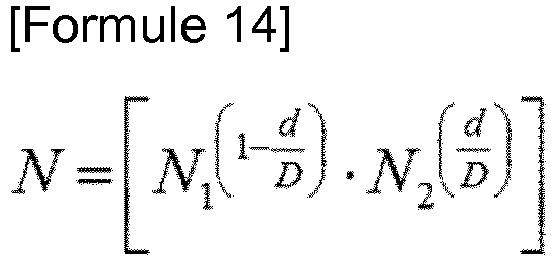
- Méthode de mise en forme tridimensionnelle selon les revendications 11 à 13,
dans laquelle, lorsque le nombre de multicouches (4) est N, une valeur moyenne de la moyenne arithmétique selon la revendication 12 et de la moyenne géométrique selon la revendication 13 est adoptée. - Méthode de mise en forme tridimensionnelle selon la revendication 11, dans laquelle, pour d dans chaque région de K régions (2) divisées, un ordre de d1 ≤ d2 ≤ ... ≤ di ≤ ... ≤ dk est détecté, et
ensuite, la formule 15 suivante reflétant un ordre de grandeur de d indiquée ci-dessous est adoptée.
- Méthode de mise en forme tridimensionnelle selon l'une quelconque des revendications 1, 6 et 11,
dans laquelle une quantité du faisceau laser ou du faisceau d'électrons appliqué par aire unitaire est ajustée en fonction de l'épaisseur de chacune des multicouches (4). - Méthode de mise en forme tridimensionnelle selon la revendication 16, dans laquelle, lorsque les sections transversales (3) des multicouches (4) respectives sont situées dans une même position dans une direction perpendiculaire à la direction de hauteur, au fur et à mesure que l'épaisseur de chacune des multicouches (4) est augmentée, la quantité de rayonnement appliqué par aire unitaire est fixée pour être plus importante.
Applications Claiming Priority (1)
| Application Number | Priority Date | Filing Date | Title |
|---|---|---|---|
| JP2016059848A JP6026688B1 (ja) | 2016-03-24 | 2016-03-24 | 三次元造形方法 |
Publications (2)
| Publication Number | Publication Date |
|---|---|
| EP3222409A1 EP3222409A1 (fr) | 2017-09-27 |
| EP3222409B1 true EP3222409B1 (fr) | 2018-05-16 |
Family
ID=57326521
Family Applications (1)
| Application Number | Title | Priority Date | Filing Date |
|---|---|---|---|
| EP16200646.4A Active EP3222409B1 (fr) | 2016-03-24 | 2016-11-25 | Procédé de mise en forme tridimensionnelle |
Country Status (7)
| Country | Link |
|---|---|
| US (1) | US9908319B2 (fr) |
| EP (1) | EP3222409B1 (fr) |
| JP (1) | JP6026688B1 (fr) |
| KR (1) | KR101752126B1 (fr) |
| CN (1) | CN106984810B (fr) |
| CA (1) | CA2949819C (fr) |
| ES (1) | ES2673818T3 (fr) |
Families Citing this family (12)
| Publication number | Priority date | Publication date | Assignee | Title |
|---|---|---|---|---|
| CN109304870B (zh) * | 2017-07-27 | 2020-03-24 | 珠海赛纳打印科技股份有限公司 | 3d打印方法及设备 |
| JP6349561B1 (ja) * | 2017-07-31 | 2018-07-04 | 福井県 | 三次元造形方法 |
| KR102151445B1 (ko) | 2017-08-30 | 2020-09-03 | 가부시키가이샤 소딕 | 적층 조형 장치 및 적층 조형물의 제조 방법 |
| EP3680294A4 (fr) | 2017-09-06 | 2020-08-12 | Mitsubishi Chemical Corporation | Copolymère de macromonomère, composition de résine époxyde, adhésif, matériau de moulage et produit durci |
| EP3511163B1 (fr) * | 2018-01-12 | 2024-03-20 | Concept Laser GmbH | Procédé de fonctionnement d'un appareil de fabrication additive d'objets tridimensionnels |
| EP3511151A1 (fr) * | 2018-01-12 | 2019-07-17 | CL Schutzrechtsverwaltungs GmbH | Procédé de fonctionnement d'au moins un appareil de fabrication additive d'objets tridimensionnels |
| KR102035454B1 (ko) * | 2019-04-24 | 2019-10-22 | 전자부품연구원 | 양자화 오류 문제를 해결하기 위한 3d 프린팅 슬라이싱 방법 |
| JP2022092076A (ja) * | 2019-04-25 | 2022-06-22 | パナソニックIpマネジメント株式会社 | 三次元形状造形物の製造方法 |
| CN110696366B (zh) * | 2019-10-21 | 2020-08-07 | 浙江大学 | 一种增材制造技术成型倾斜面的表面形貌调控方法 |
| CN113091656B (zh) * | 2021-03-25 | 2022-09-30 | 中国航发南方工业有限公司 | 一种封闭异型窄通道类零件的截面面积测量方法及系统 |
| CN113290243B (zh) * | 2021-05-31 | 2022-06-21 | 西北有色金属研究院 | 一种金属多孔材料烧结用下装式料舟 |
| CN119747660B (zh) * | 2024-12-14 | 2025-11-25 | 北京星航机电装备有限公司 | 一种用于薄壁板状结构的金属增材制造方法 |
Family Cites Families (19)
| Publication number | Priority date | Publication date | Assignee | Title |
|---|---|---|---|---|
| US4247508B1 (en) * | 1979-12-03 | 1996-10-01 | Dtm Corp | Molding process |
| JP3458593B2 (ja) * | 1996-04-23 | 2003-10-20 | 松下電工株式会社 | 三次元形状の形成方法 |
| US6084980A (en) * | 1997-05-13 | 2000-07-04 | 3D Systems, Inc. | Method of and apparatus for deriving data intermediate to cross-sectional data descriptive of a three-dimensional object |
| JP3446733B2 (ja) | 2000-10-05 | 2003-09-16 | 松下電工株式会社 | 三次元形状造形物の製造方法及びその装置 |
| EP1441897B1 (fr) * | 2001-10-30 | 2006-08-09 | CL Schutzrechtsverwaltungs GmbH | Procede de production de pieces frittees tridimensionnelles |
| SE524421C2 (sv) * | 2002-12-19 | 2004-08-10 | Arcam Ab | Anordning samt metod för framställande av en tredimensionell produkt |
| US7497977B2 (en) * | 2003-01-29 | 2009-03-03 | Hewlett-Packard Development Company, L.P. | Methods and systems for producing an object through solid freeform fabrication by varying a concentration of ejected material applied to an object layer |
| JP2004284025A (ja) | 2003-03-19 | 2004-10-14 | Hitachi Ltd | 積層造形法および積層造形装置 |
| CN101835554B (zh) * | 2007-10-26 | 2012-08-22 | 松下电器产业株式会社 | 金属粉末烧结部件的制造装置及制造方法 |
| JP5186306B2 (ja) * | 2008-08-25 | 2013-04-17 | パナソニック株式会社 | 三次元形状造形物の製造方法 |
| JP5543740B2 (ja) * | 2009-08-07 | 2014-07-09 | 株式会社コンピュータシステム研究所 | 立体模型製造方法および立体模型 |
| JP2012162025A (ja) * | 2011-02-08 | 2012-08-30 | Dainippon Printing Co Ltd | Ledリフレクタの成型方法 |
| JP2013067036A (ja) | 2011-09-21 | 2013-04-18 | Keyence Corp | 3次元造形装置 |
| US20130186549A1 (en) * | 2011-09-23 | 2013-07-25 | Stratasys, Inc. | Layer transfusion for additive manufacturing |
| CH705750A1 (de) * | 2011-10-31 | 2013-05-15 | Alstom Technology Ltd | Verfahren zur Herstellung von Komponenten oder Abschnitten, die aus einer Hochtemperatur-Superlegierung bestehen. |
| JP2015030883A (ja) * | 2013-08-02 | 2015-02-16 | 株式会社ソディック | 三次元形状の積層造形物の製造方法およびその製造装置 |
| EP2865465B1 (fr) * | 2013-09-27 | 2018-01-17 | Ansaldo Energia IP UK Limited | Procédé de fabrication d'un composant métallique par fabrication laser d'un additif |
| JP6241244B2 (ja) | 2013-12-10 | 2017-12-06 | セイコーエプソン株式会社 | 三次元造形物製造装置、三次元造形物の製造方法および三次元造形物 |
| US20160282848A1 (en) * | 2015-03-27 | 2016-09-29 | Arcam Ab | Method for additive manufacturing |
-
2016
- 2016-03-24 JP JP2016059848A patent/JP6026688B1/ja active Active
- 2016-11-24 CA CA2949819A patent/CA2949819C/fr active Active
- 2016-11-25 EP EP16200646.4A patent/EP3222409B1/fr active Active
- 2016-11-25 ES ES16200646.4T patent/ES2673818T3/es active Active
- 2016-12-21 US US15/386,559 patent/US9908319B2/en active Active
-
2017
- 2017-01-12 KR KR1020170004963A patent/KR101752126B1/ko not_active Expired - Fee Related
- 2017-01-19 CN CN201710043260.0A patent/CN106984810B/zh active Active
Non-Patent Citations (1)
| Title |
|---|
| None * |
Also Published As
| Publication number | Publication date |
|---|---|
| US9908319B2 (en) | 2018-03-06 |
| EP3222409A1 (fr) | 2017-09-27 |
| ES2673818T3 (es) | 2018-06-25 |
| CN106984810B (zh) | 2018-08-28 |
| KR101752126B1 (ko) | 2017-06-28 |
| US20170274597A1 (en) | 2017-09-28 |
| CA2949819C (fr) | 2018-04-10 |
| CN106984810A (zh) | 2017-07-28 |
| CA2949819A1 (fr) | 2017-01-25 |
| JP6026688B1 (ja) | 2016-11-16 |
| JP2017170771A (ja) | 2017-09-28 |
Similar Documents
| Publication | Publication Date | Title |
|---|---|---|
| EP3222409B1 (fr) | Procédé de mise en forme tridimensionnelle | |
| US20230280714A1 (en) | Computerized tool path generation | |
| Kulkarni et al. | A review of process planning techniques in layered manufacturing | |
| Jin et al. | A parallel-based path generation method for fused deposition modeling | |
| Mohan Pandey et al. | Slicing procedures in layered manufacturing: a review | |
| EP3613995B1 (fr) | Procédé de conception de pale de machine à fluide à écoulement axial, et pale | |
| CN109434104B (zh) | 一种用于金属激光选区熔化成形工艺的扫描方法 | |
| JP6458182B1 (ja) | 三次元造形方法 | |
| Qin et al. | Adaptive toolpath generation for distortion reduction in laser powder bed fusion process | |
| Behera et al. | Tool path generation for single point incremental forming using intelligent sequencing and multi-step mesh morphing techniques | |
| CN114265367B (zh) | 一种高精度参数路径插补方法及系统 | |
| CN103464560A (zh) | 具有纹理表面的成形工具 | |
| WO2020033932A2 (fr) | Procédé d'évaluation et de reconception automatisées de la qualité d'impression 3d | |
| Kumar et al. | Volume deviation in direct slicing | |
| Tarabanis | Path planning in the Proteus rapid prototyping system | |
| EP3441222A1 (fr) | Procédé de réglage d'angle de façonnage pour un produit moulé tridimensionnel | |
| CN113369497A (zh) | 一种用于厚度变化较大零件的粉末床增材制造的分区方法 | |
| US7920140B2 (en) | System for controlling deformation | |
| US8325183B2 (en) | System and method for determining a position for an addendum mesh node | |
| CN104820744A (zh) | 一种曲面数控加工中面向nurbs刀具路径的生成方法 | |
| Park et al. | A surface area calculation and CAPP system for non-axisymmetric deep drawing products | |
| Im et al. | A CNC cutting trajectory algorithm for profiled edge lamination tooling | |
| JP5453022B2 (ja) | Camシステム | |
| JP5489589B2 (ja) | Camシステム | |
| HK1240888A1 (en) | Three-dimensional shaping method |
Legal Events
| Date | Code | Title | Description |
|---|---|---|---|
| PUAI | Public reference made under article 153(3) epc to a published international application that has entered the european phase |
Free format text: ORIGINAL CODE: 0009012 |
|
| AK | Designated contracting states |
Kind code of ref document: A1 Designated state(s): AL AT BE BG CH CY CZ DE DK EE ES FI FR GB GR HR HU IE IS IT LI LT LU LV MC MK MT NL NO PL PT RO RS SE SI SK SM TR |
|
| AX | Request for extension of the european patent |
Extension state: BA ME |
|
| 17P | Request for examination filed |
Effective date: 20171103 |
|
| RBV | Designated contracting states (corrected) |
Designated state(s): AL AT BE BG CH CY CZ DE DK EE ES FI FR GB GR HR HU IE IS IT LI LT LU LV MC MK MT NL NO PL PT RO RS SE SI SK SM TR |
|
| REG | Reference to a national code |
Ref country code: DE Ref legal event code: R079 Ref document number: 602016003116 Country of ref document: DE Free format text: PREVIOUS MAIN CLASS: B29C0067000000 Ipc: B33Y0050020000 |
|
| GRAP | Despatch of communication of intention to grant a patent |
Free format text: ORIGINAL CODE: EPIDOSNIGR1 |
|
| RIC1 | Information provided on ipc code assigned before grant |
Ipc: B33Y 10/00 20150101ALI20171221BHEP Ipc: B29C 64/386 20170101ALI20171221BHEP Ipc: B33Y 50/02 20150101AFI20171221BHEP Ipc: B22F 3/105 20060101ALN20171221BHEP Ipc: B29C 64/153 20170101ALI20171221BHEP |
|
| RIC1 | Information provided on ipc code assigned before grant |
Ipc: B29C 64/386 20170101ALI20180111BHEP Ipc: B29C 64/153 20170101ALI20180111BHEP Ipc: B33Y 50/02 20150101AFI20180111BHEP Ipc: B33Y 10/00 20150101ALI20180111BHEP Ipc: B22F 3/105 20060101ALN20180111BHEP |
|
| INTG | Intention to grant announced |
Effective date: 20180124 |
|
| RIN1 | Information on inventor provided before grant (corrected) |
Inventor name: AMAYA, KOUICHI Inventor name: ISHIMOTO, KOUSUKE |
|
| GRAS | Grant fee paid |
Free format text: ORIGINAL CODE: EPIDOSNIGR3 |
|
| GRAA | (expected) grant |
Free format text: ORIGINAL CODE: 0009210 |
|
| AK | Designated contracting states |
Kind code of ref document: B1 Designated state(s): AL AT BE BG CH CY CZ DE DK EE ES FI FR GB GR HR HU IE IS IT LI LT LU LV MC MK MT NL NO PL PT RO RS SE SI SK SM TR |
|
| REG | Reference to a national code |
Ref country code: GB Ref legal event code: FG4D |
|
| REG | Reference to a national code |
Ref country code: CH Ref legal event code: EP |
|
| REG | Reference to a national code |
Ref country code: IE Ref legal event code: FG4D |
|
| REG | Reference to a national code |
Ref country code: DE Ref legal event code: R096 Ref document number: 602016003116 Country of ref document: DE |
|
| REG | Reference to a national code |
Ref country code: AT Ref legal event code: REF Ref document number: 999171 Country of ref document: AT Kind code of ref document: T Effective date: 20180615 |
|
| REG | Reference to a national code |
Ref country code: ES Ref legal event code: FG2A Ref document number: 2673818 Country of ref document: ES Kind code of ref document: T3 Effective date: 20180625 |
|
| REG | Reference to a national code |
Ref country code: NL Ref legal event code: MP Effective date: 20180516 |
|
| REG | Reference to a national code |
Ref country code: LT Ref legal event code: MG4D |
|
| PG25 | Lapsed in a contracting state [announced via postgrant information from national office to epo] |
Ref country code: NO Free format text: LAPSE BECAUSE OF FAILURE TO SUBMIT A TRANSLATION OF THE DESCRIPTION OR TO PAY THE FEE WITHIN THE PRESCRIBED TIME-LIMIT Effective date: 20180816 Ref country code: FI Free format text: LAPSE BECAUSE OF FAILURE TO SUBMIT A TRANSLATION OF THE DESCRIPTION OR TO PAY THE FEE WITHIN THE PRESCRIBED TIME-LIMIT Effective date: 20180516 Ref country code: SE Free format text: LAPSE BECAUSE OF FAILURE TO SUBMIT A TRANSLATION OF THE DESCRIPTION OR TO PAY THE FEE WITHIN THE PRESCRIBED TIME-LIMIT Effective date: 20180516 Ref country code: LT Free format text: LAPSE BECAUSE OF FAILURE TO SUBMIT A TRANSLATION OF THE DESCRIPTION OR TO PAY THE FEE WITHIN THE PRESCRIBED TIME-LIMIT Effective date: 20180516 Ref country code: BG Free format text: LAPSE BECAUSE OF FAILURE TO SUBMIT A TRANSLATION OF THE DESCRIPTION OR TO PAY THE FEE WITHIN THE PRESCRIBED TIME-LIMIT Effective date: 20180816 |
|
| PG25 | Lapsed in a contracting state [announced via postgrant information from national office to epo] |
Ref country code: GR Free format text: LAPSE BECAUSE OF FAILURE TO SUBMIT A TRANSLATION OF THE DESCRIPTION OR TO PAY THE FEE WITHIN THE PRESCRIBED TIME-LIMIT Effective date: 20180817 Ref country code: NL Free format text: LAPSE BECAUSE OF FAILURE TO SUBMIT A TRANSLATION OF THE DESCRIPTION OR TO PAY THE FEE WITHIN THE PRESCRIBED TIME-LIMIT Effective date: 20180516 Ref country code: LV Free format text: LAPSE BECAUSE OF FAILURE TO SUBMIT A TRANSLATION OF THE DESCRIPTION OR TO PAY THE FEE WITHIN THE PRESCRIBED TIME-LIMIT Effective date: 20180516 Ref country code: HR Free format text: LAPSE BECAUSE OF FAILURE TO SUBMIT A TRANSLATION OF THE DESCRIPTION OR TO PAY THE FEE WITHIN THE PRESCRIBED TIME-LIMIT Effective date: 20180516 Ref country code: RS Free format text: LAPSE BECAUSE OF FAILURE TO SUBMIT A TRANSLATION OF THE DESCRIPTION OR TO PAY THE FEE WITHIN THE PRESCRIBED TIME-LIMIT Effective date: 20180516 |
|
| REG | Reference to a national code |
Ref country code: AT Ref legal event code: MK05 Ref document number: 999171 Country of ref document: AT Kind code of ref document: T Effective date: 20180516 |
|
| PG25 | Lapsed in a contracting state [announced via postgrant information from national office to epo] |
Ref country code: CZ Free format text: LAPSE BECAUSE OF FAILURE TO SUBMIT A TRANSLATION OF THE DESCRIPTION OR TO PAY THE FEE WITHIN THE PRESCRIBED TIME-LIMIT Effective date: 20180516 Ref country code: RO Free format text: LAPSE BECAUSE OF FAILURE TO SUBMIT A TRANSLATION OF THE DESCRIPTION OR TO PAY THE FEE WITHIN THE PRESCRIBED TIME-LIMIT Effective date: 20180516 Ref country code: AT Free format text: LAPSE BECAUSE OF FAILURE TO SUBMIT A TRANSLATION OF THE DESCRIPTION OR TO PAY THE FEE WITHIN THE PRESCRIBED TIME-LIMIT Effective date: 20180516 Ref country code: EE Free format text: LAPSE BECAUSE OF FAILURE TO SUBMIT A TRANSLATION OF THE DESCRIPTION OR TO PAY THE FEE WITHIN THE PRESCRIBED TIME-LIMIT Effective date: 20180516 Ref country code: DK Free format text: LAPSE BECAUSE OF FAILURE TO SUBMIT A TRANSLATION OF THE DESCRIPTION OR TO PAY THE FEE WITHIN THE PRESCRIBED TIME-LIMIT Effective date: 20180516 Ref country code: PL Free format text: LAPSE BECAUSE OF FAILURE TO SUBMIT A TRANSLATION OF THE DESCRIPTION OR TO PAY THE FEE WITHIN THE PRESCRIBED TIME-LIMIT Effective date: 20180516 Ref country code: SK Free format text: LAPSE BECAUSE OF FAILURE TO SUBMIT A TRANSLATION OF THE DESCRIPTION OR TO PAY THE FEE WITHIN THE PRESCRIBED TIME-LIMIT Effective date: 20180516 |
|
| REG | Reference to a national code |
Ref country code: DE Ref legal event code: R097 Ref document number: 602016003116 Country of ref document: DE |
|
| PG25 | Lapsed in a contracting state [announced via postgrant information from national office to epo] |
Ref country code: SM Free format text: LAPSE BECAUSE OF FAILURE TO SUBMIT A TRANSLATION OF THE DESCRIPTION OR TO PAY THE FEE WITHIN THE PRESCRIBED TIME-LIMIT Effective date: 20180516 |
|
| PLBE | No opposition filed within time limit |
Free format text: ORIGINAL CODE: 0009261 |
|
| STAA | Information on the status of an ep patent application or granted ep patent |
Free format text: STATUS: NO OPPOSITION FILED WITHIN TIME LIMIT |
|
| 26N | No opposition filed |
Effective date: 20190219 |
|
| PG25 | Lapsed in a contracting state [announced via postgrant information from national office to epo] |
Ref country code: LU Free format text: LAPSE BECAUSE OF NON-PAYMENT OF DUE FEES Effective date: 20181125 Ref country code: MC Free format text: LAPSE BECAUSE OF FAILURE TO SUBMIT A TRANSLATION OF THE DESCRIPTION OR TO PAY THE FEE WITHIN THE PRESCRIBED TIME-LIMIT Effective date: 20180516 |
|
| REG | Reference to a national code |
Ref country code: BE Ref legal event code: MM Effective date: 20181130 |
|
| REG | Reference to a national code |
Ref country code: IE Ref legal event code: MM4A |
|
| PG25 | Lapsed in a contracting state [announced via postgrant information from national office to epo] |
Ref country code: IE Free format text: LAPSE BECAUSE OF NON-PAYMENT OF DUE FEES Effective date: 20181125 |
|
| PG25 | Lapsed in a contracting state [announced via postgrant information from national office to epo] |
Ref country code: BE Free format text: LAPSE BECAUSE OF NON-PAYMENT OF DUE FEES Effective date: 20181130 Ref country code: AL Free format text: LAPSE BECAUSE OF FAILURE TO SUBMIT A TRANSLATION OF THE DESCRIPTION OR TO PAY THE FEE WITHIN THE PRESCRIBED TIME-LIMIT Effective date: 20180516 |
|
| PG25 | Lapsed in a contracting state [announced via postgrant information from national office to epo] |
Ref country code: MT Free format text: LAPSE BECAUSE OF NON-PAYMENT OF DUE FEES Effective date: 20181125 |
|
| PG25 | Lapsed in a contracting state [announced via postgrant information from national office to epo] |
Ref country code: TR Free format text: LAPSE BECAUSE OF FAILURE TO SUBMIT A TRANSLATION OF THE DESCRIPTION OR TO PAY THE FEE WITHIN THE PRESCRIBED TIME-LIMIT Effective date: 20180516 |
|
| PG25 | Lapsed in a contracting state [announced via postgrant information from national office to epo] |
Ref country code: PT Free format text: LAPSE BECAUSE OF FAILURE TO SUBMIT A TRANSLATION OF THE DESCRIPTION OR TO PAY THE FEE WITHIN THE PRESCRIBED TIME-LIMIT Effective date: 20180516 |
|
| PG25 | Lapsed in a contracting state [announced via postgrant information from national office to epo] |
Ref country code: CY Free format text: LAPSE BECAUSE OF FAILURE TO SUBMIT A TRANSLATION OF THE DESCRIPTION OR TO PAY THE FEE WITHIN THE PRESCRIBED TIME-LIMIT Effective date: 20180516 Ref country code: MK Free format text: LAPSE BECAUSE OF NON-PAYMENT OF DUE FEES Effective date: 20180516 Ref country code: HU Free format text: LAPSE BECAUSE OF FAILURE TO SUBMIT A TRANSLATION OF THE DESCRIPTION OR TO PAY THE FEE WITHIN THE PRESCRIBED TIME-LIMIT; INVALID AB INITIO Effective date: 20161125 |
|
| PG25 | Lapsed in a contracting state [announced via postgrant information from national office to epo] |
Ref country code: IS Free format text: LAPSE BECAUSE OF FAILURE TO SUBMIT A TRANSLATION OF THE DESCRIPTION OR TO PAY THE FEE WITHIN THE PRESCRIBED TIME-LIMIT Effective date: 20180916 |
|
| PG25 | Lapsed in a contracting state [announced via postgrant information from national office to epo] |
Ref country code: SI Free format text: LAPSE BECAUSE OF NON-PAYMENT OF DUE FEES Effective date: 20181125 |
|
| PGFP | Annual fee paid to national office [announced via postgrant information from national office to epo] |
Ref country code: CH Payment date: 20241201 Year of fee payment: 9 |
|
| PGFP | Annual fee paid to national office [announced via postgrant information from national office to epo] |
Ref country code: DE Payment date: 20251029 Year of fee payment: 10 |
|
| PGFP | Annual fee paid to national office [announced via postgrant information from national office to epo] |
Ref country code: GB Payment date: 20251125 Year of fee payment: 10 |
|
| PGFP | Annual fee paid to national office [announced via postgrant information from national office to epo] |
Ref country code: IT Payment date: 20251127 Year of fee payment: 10 |
|
| PGFP | Annual fee paid to national office [announced via postgrant information from national office to epo] |
Ref country code: FR Payment date: 20251128 Year of fee payment: 10 |
|
| PGFP | Annual fee paid to national office [announced via postgrant information from national office to epo] |
Ref country code: ES Payment date: 20251201 Year of fee payment: 10 |