EP3222540A1 - Dispositif de stérilisation à faisceaux d'électrons - Google Patents
Dispositif de stérilisation à faisceaux d'électrons Download PDFInfo
- Publication number
- EP3222540A1 EP3222540A1 EP15861399.2A EP15861399A EP3222540A1 EP 3222540 A1 EP3222540 A1 EP 3222540A1 EP 15861399 A EP15861399 A EP 15861399A EP 3222540 A1 EP3222540 A1 EP 3222540A1
- Authority
- EP
- European Patent Office
- Prior art keywords
- electron beam
- power supply
- units
- rotational
- beam emission
- Prior art date
- Legal status (The legal status is an assumption and is not a legal conclusion. Google has not performed a legal analysis and makes no representation as to the accuracy of the status listed.)
- Withdrawn
Links
Images






Classifications
-
- A—HUMAN NECESSITIES
- A61—MEDICAL OR VETERINARY SCIENCE; HYGIENE
- A61L—METHODS OR APPARATUS FOR STERILISING MATERIALS OR OBJECTS IN GENERAL; DISINFECTION, STERILISATION OR DEODORISATION OF AIR; CHEMICAL ASPECTS OF BANDAGES, DRESSINGS, ABSORBENT PADS OR SURGICAL ARTICLES; MATERIALS FOR BANDAGES, DRESSINGS, ABSORBENT PADS OR SURGICAL ARTICLES
- A61L2/00—Disinfection or sterilisation of materials or objects, in general; Accessories therefor
- A61L2/02—Disinfection or sterilisation of materials or objects, in general; Accessories therefor using physical processes
- A61L2/08—Radiation
- A61L2/087—Particle radiation, e.g. electron-beam, alpha or beta radiation
-
- A—HUMAN NECESSITIES
- A61—MEDICAL OR VETERINARY SCIENCE; HYGIENE
- A61L—METHODS OR APPARATUS FOR STERILISING MATERIALS OR OBJECTS IN GENERAL; DISINFECTION, STERILISATION OR DEODORISATION OF AIR; CHEMICAL ASPECTS OF BANDAGES, DRESSINGS, ABSORBENT PADS OR SURGICAL ARTICLES; MATERIALS FOR BANDAGES, DRESSINGS, ABSORBENT PADS OR SURGICAL ARTICLES
- A61L2103/00—Materials or objects being the target of disinfection or sterilisation
- A61L2103/23—Containers other than laboratory or medical, e.g. bottles or mail
-
- A—HUMAN NECESSITIES
- A61—MEDICAL OR VETERINARY SCIENCE; HYGIENE
- A61L—METHODS OR APPARATUS FOR STERILISING MATERIALS OR OBJECTS IN GENERAL; DISINFECTION, STERILISATION OR DEODORISATION OF AIR; CHEMICAL ASPECTS OF BANDAGES, DRESSINGS, ABSORBENT PADS OR SURGICAL ARTICLES; MATERIALS FOR BANDAGES, DRESSINGS, ABSORBENT PADS OR SURGICAL ARTICLES
- A61L2202/00—Aspects relating to methods or apparatus for disinfecting or sterilising materials or objects
- A61L2202/10—Apparatus features
- A61L2202/12—Apparatus for isolating biocidal substances from the environment
- A61L2202/121—Sealings, e.g. doors, covers, valves, sluices
Definitions
- the present invention relates to an electron beam sterilization device for applying an electron beam onto an inner surface of containers for foods, liquid drugs or the like being conveyed, thereby to sterilize the containers.
- Such electron beam sterilization devices have conventionally been configured as shown in Fig. 12 , in which a plurality of electron beam emission units 101 have nozzles 102, and containers 104 retained by a plurality of retaining devices 103 are moved vertically to insert the nozzles 102 into the containers 104, and electron beams are emitted from emission windows of the nozzles 102 to sterilize the interiors of the containers 104.
- Such electron beam sterilization devices 100 include a rotational member 108 to be rotationally driven around a vertical rotational axis 107 by a rotational drive unit.
- the rotational member 108 includes upper and lower rotational tables 109, 110 having a disk shape.
- the electron beam emission units 101 are arranged on the outer peripheral portion of the upper rotational table 109 at regular angular intervals in the circumferential direction.
- Each of the electron beam emission units 101 includes a nozzle 102 projecting downward.
- the retaining devices 103 are provided on the lower rotational table 110 of the rotational member 108 so as to be capable of elevation and are opposed to the associated nozzles 102 from below.
- the power supply units 112 and the electron beam emission units 101 are electrically connected to each other via power supply cables 113.
- the rotational member 108 rotates while the containers 104 are retained by the retaining devices 103, and as shown by the virtual line in Fig. 12 , the retaining devices 103 are elevated so as to elevate the containers 104 and insert the nozzles 102 into the containers 104. Electron beams 105 are emitted from the emission windows of the nozzles 102 to sterilize the interiors of the containers 104.
- the electron beam sterilization devices 100 including the rotational member 108 as described above are disclosed in, for example, Patent Literature 1.
- Patent Literature 1 Japanese Patent Application Publication No. 2013-86822
- the power supply units 112 are provided on the upper rotational table 109, and thus are positioned in an upper portion of the rotational member 108. Since the power supply units 112 have a large weight, the upper portion of the rotational member 108 has a large weight due to the weight of the power supply units 112. The center of gravity of the whole rotational member 108 is positioned high, and therefore, the rotational member 108 tends to rotate unstably.
- One object of the present invention is to provide an electron beam sterilization device in which the rotational member rotates stably.
- the first aspect of the present invention pertains to an electron beam sterilization device in which at least one of nozzles of electron beam emission units and containers are moved relative to the other so as to insert the nozzles into the containers through opening portions thereof, and interiors of the containers are sterilized by electron beams emitted from emission windows of the nozzles
- the electron beam sterilization device comprising: an upper stage, a middle stage, and a lower stage provided in a rotational member configured to be rotated around a vertical rotational shaft; a plurality of electron beam emission units arranged on the upper stage along a circumferential direction and having the nozzles projected downward; a plurality of retaining devices arranged on the middle stage in association with the nozzles and configured to retain the containers; a plurality of power supply units arranged on the lower stage and configured to supply power to the electron beam emission units, respectively; and a plurality of power supply cables extending from the power supply units to the upper stage along the rotational shaft and connected to the plurality of electron beam emission units, respectively.
- the power supply units are provided on the lower stage of the rotational member, and therefore, the center of gravity of the whole rotational member is lowered, thereby stabilizing the rotation of the rotational member.
- the electron beam emission units and the power supply units are arranged in phase, and the electron beam emission units and the power supply units connected via same power supply cables are arranged in phases differentiated in a circumferential direction of the rotational member, whereby at least portions of the power supply cables extending from the power supply units toward the rotational shaft in the lower stage have a large radius of curvature.
- the electron beam emission units and the power supply units connected via same power supply cables are arranged at positions differentiated in the circumferential direction of the rotational member. Therefore, the power supply cables extending from the power supply units can be bent along the circumferential direction of the rotational member toward the rotational shaft, whereby the power supply cables can have a large radius of curvature in the lower stage. This enables a thick power supply cable to be bent easily and facilitates wiring of the power supply cable.
- the middle stage of the rotational member has a plurality of elevation units for elevating and lowering the containers so as to insert the nozzles into the opening portions.
- the containers are elevated and lowered by the elevation units so as to insert the nozzles of the electron beam emission units into the containers, and electron beams are emitted from the emission windows of the nozzles to sterilize the interiors of the containers.
- the rotational member includes a blocking cylinder
- the power cables extend from the power supply units through the blocking cylinder and are connected to the electron beam emission units
- the blocking cylinder is made of a blocking member configured to block at least one of a magnetic field generated from the power supply cables and radiations generated from the electron beam emission units.
- the blocking cylinder blocks at least one of a magnetic field generated from the power supply cables and radiations generated from the electron beam emission units. Therefore, when the magnetic field is blocked, the electron beams emitted from the nozzles of the electron beam emission units can be prevented from being bent by the magnetic field generated from the power supply cables, and it can be ensured that the electron beams are applied to the interiors of the containers and the interiors of the containers are sterilized.
- the power supply cables can be prevented from being deteriorated due to the radiations.
- the rotational member rotates stably, ensuring that the electron beams are emitted into the containers and the interiors of the containers are sterilized.
- an electron beam sterilization device 1 may apply electron beams to plastic bottles 2 (an example of bottles) for sterilization, as shown in Figs. 1 and 2 .
- the plastic bottles 2 may be formed from, for example, a preform product having a test tube shape (with a U-shaped longitudinal section opened at the upper end thereof) subjected to blow molding.
- the electron beam sterilization device 1 may generally include four chambers 5 to 8 in a cover member 4.
- the chambers 5 to 8, which may be arranged from the upstream side of the conveyance path of the plastic bottles 2, may include an outer surface sterilization chamber 5 in which electron beams are applied to outer surfaces of the plastic bottles 2 fed from outside so as to perform sterilization, an inner surface sterilization chamber 6 in which electron beams are applied to inner surfaces of the plastic bottles 2 so as to perform sterilization, a blocking chamber 7 for blocking radiations produced by application of the electron beams to the plastic bottles 2, and a sorting chamber 8 in which the plastic bottles 2 that are insufficiently sterilized (hereinafter referred to simply as "defective products") are ejected.
- the cover member 4 there may be provided a plurality of partition walls 9 for defining the chambers 5 to 8 and an intermediate frame 10 (see Figs. 1 and 4 ) positioned horizontally.
- the outer surface sterilization chamber 5 may include an input portion 11 through which plastic bottles 2 are put in from outside, a conveyor portion 12 for conveying the plastic bottles 2 having been put in, and an outer-surface electron beam emission unit 13 for applying electron beams to outer surfaces of the plastic bottles 2 being conveyed by the conveyor portion 12.
- the plastic bottles 2 retained by the clamp units 17 may be moved vertically with respect to the nozzles 16 of the electron beam emission units 15, so as to insert the nozzles 16 into the plastic bottles 2 through the opening portions 18, and electron beams may be emitted from emission windows 19 of the nozzles 16 to sterilize the interiors of the plastic bottles 2.
- the inner surface sterilization chamber 6 may include the rotational member 22 that may be rotationally driven around a vertical rotational axis 24 by the rotational drive unit 23.
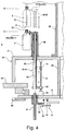
- the rotational member 22 may include an upper rotational table 25 (an example of the upper stage), a lower rotational table 26 (an example of the lower stage), an intermediate rotational table 27 (an example of the middle stage) provided between the upper rotational table 25 and the lower rotational table 26, a blocking cylinder 29 having a circular shape and provided between the upper rotational table 25 and the intermediate rotational table 27, a mounting cylinder 30 having a circular shape and provided on the lower surface of the intermediate rotational table 27, an intermediate mounting table 31 (an example of the middle stage) having a ring shape and provided on the lower end of the mounting cylinder 30, first and second rotational shafts 33, 34 having a cylindrical shape, a lower cylindrical frame 35, and a connection unit 39.
- the first and second rotational shafts 33, 34 may be provided in the central portion of the rotational member 22 at an upper and lower positions, respectively.
- a fixed shaft 36 may extend through the first and second rotational shafts 33, 34 and may be mounted to a bottom frame 37 of the inner surface sterilization chamber 6. Both the first and second rotational shafts 33, 34 may be rotatably supported by the fixed shaft 36 via a bearing 38.
- the upper rotational table 25 may have a disk shape.
- a plurality of electron beam emission units 15, each projecting the nozzle 16 downward, may be arranged on the outer peripheral portion of the upper rotational table 25 at regular angular intervals.
- An upper blocking member 40 may be provided on the upper rotational table 25, and the electron beam emission units 15 may be positioned inside the upper blocking member 40.
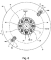
- the intermediate rotational table 27 may have a disk shape. As shown in Fig. 8 , there may be provided a plurality of partition plates 41 inside the blocking cylinder 29 at regular intervals in the circumferential direction A. As shown in Figs. 1 and 3 , the clamp units 17 may be provided on the outer peripheral portion of the intermediate rotational table 27 at regular intervals. Further, on the outer peripheral portion of the intermediate rotational table 27, there may be provided a plurality of elevation units 43 for elevating and lowering the clamp units 17, and opening/closing mechanisms 44.
- the clamp units 17 may be provided in association with the nozzles 16 and may each include a pair of clamp arms 46a, 46b capable of opening and closing and a spring 47 (an example of biasing member) that biases the pair of clamp arms 46a, 46b toward the respective closing directions.
- the elevation unit 43 may include a shaft sleeve 50 guided by a guide member 49 so as to be capable of elevation, a screw shaft 51 arranged in parallel with the shaft sleeve 50, an internal thread member 52 provided on a lower portion of the shaft sleeve 50 and threadably engaged with the screw shaft 51, and a servomotor 53 for rotationally driving the screw shaft 51.
- the servomotor 53 may be mounted on the intermediate mounting table 31 of the rotational member 22.
- the clamp arms 46a, 46b may be provided on the upper end of the shaft sleeve 50.
- the internal thread member 52 may be moved in the axial direction of the screw shaft 51, and the clamp arms 46a, 46b may be elevated or lowered along with the shaft sleeve 50.
- the opening/closing mechanism 44 may operate to open and close the clamp arms 46a, 46b.
- the opening/closing mechanism 44 may include an inner shaft 55 inserted in the shaft sleeve 50 and capable of rotating around the axis thereof, a cam 56 provided on the upper end of the inner shaft 55, and a cam unit 57 for rotating the inner shaft 55.
- the cam unit 57 may include a cam lever 58 and a cam roller 59.
- the cam lever 58 may be fitted on a lower portion of the inner shaft 55 via a spline 61.
- the cam roller 59 may be provided on a distal end portion of the cam lever 58.
- the cam lever 58 may be mounted to the intermediate mounting table 31 so as to be capable of swinging.
- the inner shaft 55 can be elevated and lowered along with the shaft sleeve 50 with respect to the cam lever 58.
- the inner surface sterilization chamber 6 may include a fixed cam member 60.
- the cam roller 59 may contact with the fixed cam member 60 to cause the cam lever 58 to swing.
- the inner shaft 55 may rotate and the cam 56 may swing, causing the clamp arms 46a, 46b to open or close.
- the lower rotational table 26 may have a disk shape and may be rotatably supported on the bottom frame 37 via a support member 62.
- the lower cylindrical frame 35 may be mounted on the lower rotational table 26.
- the lower end of the second rotational shaft 34 and the upper end of the lower cylindrical frame 35 may be connected via the connection unit 39.
- the connection unit 39 may absorb the misalignment of the lower rotational table 26.
- the lower rotational table 26 there may be provided a plurality of power supply units 71 for supplying power to the electron beam emission units 15.
- the electron beam emission units 15 and the power supply units 71 may be associated with each other in one-to-one relationship and may be opposed to each other in the vertical direction. Since the power supply units 71 have a large weight, the rotational accuracy of the lower rotational table 26 may be maintained to be low, whereas the rotational accuracy of the intermediate rotational table 27 may be maintained to be high. The difference in the rotational accuracy may enable the connection unit 39 to absorb the misalignment occurring to the lower rotational table 26. As a result, the rotation of the rotational member 22 may not be hindered.
- the electron beam emission units 15 and the power supply units 71 may be connected via the power supply cables 72.
- Each of the power supply cables 72 may include a lower wire portion 72a, a vertical wire portion 72b, and an upper wire portion 72c.
- the lower wire portion 72a may extend from the power supply unit 71 toward the rotational axis 24 and reach the second rotational shaft 34.
- the vertical wire portion 72b may extend upward from the lower wire portion 72a along the first and second rotational shafts 33, 34.
- the upper wire portion 72c may have a semicircular shape and may be curved from the upper end of the vertical wire portion 72b toward the outer periphery and connected to the electron beam emission unit 15.
- FIG. 5 shows eight electron beam emission units 15 and eight power supply units 71.
- this configuration is not limitative, and actually a larger number of electron beam emission units 15 and power supply units 71 may be provided.
- the vertical wire portion 72b of the power supply cable 72 may extend through the blocking cylinder 29 and the mounting cylinder 30.
- the partition wall 41 may be interposed between one vertical wire portion 72b and another adjacent thereto.
- the blocking cylinder 29 may include an outer member 29a having a high corrosion resistance and a magnetic field blocking member 29b and a radiation blocking member 29c provided inside the outer member 29a.
- the outer member 29a may be made of, e.g., stainless steel.
- the magnetic field blocking member 29b may be made of a material that can well block the magnetic field generated from the power supply cable 72, e.g., Mu-Metal having a high magnetic permeability (e.g., a permalloy having Mo, Mn, Cu, or Cr added thereto or 78Ni-5Mo-4Cu-Fe and 36Ni-Fe) or a high magnetic permeability metal (e.g., an alloy of iron and nickel).
- the radiation blocking member 29c may be made of a material that can well block the radiations generated from the electron beam emission unit 15. One example of such material is lead.
- the electron beam emission units 15 and the power supply units 71 may be arranged in phase. More specifically, as shown in Fig. 5 , the electron beam emission units 15 and the power supply units 71 provided therebelow may be arranged in the same positions in the circumferential direction A of the rotational member 22. However, the electron beam emission unit 15 and the power supply unit 71 connected via the same power supply cable 72 may be arranged in phases differentiated in the circumferential direction A of the rotational member 22. More specifically, as shown in Figs. 6 and 7 , the electron beam emission unit 15 and the power supply unit 71 connected via the same power supply cable 72 may be arranged at positions differentiated by an angle B in the circumferential direction A of the rotational member 22.
- the distance E from the power supply unit 71 to the vertical wire portion 72b of the power supply cable 72 may be larger.
- the lower wire portion 72a may be bent in an arc shape in the circumferential direction A of the rotational member 22 in a plan view, and may also be bent upward and continuous to the vertical wire portion 72b, as shown in Figs. 1 and 7 .
- a ring gear 64 may be provided in the outer periphery of the intermediate mounting table 31 over the whole circumference thereof.
- the rotational drive unit 23 may include a drive gear 65 meshing with the ring gear 64, a motor 66, a transmission mechanism 67 that transmits the rotation of the motor 66 to the drive gear 65.
- the transmission mechanism 67 may include a pair of sprockets 68, 69 and a chain 70 wound around the sprockets 68, 69.
- the drive gear 65 and the motor 66 may be provided on the intermediate frame 10.
- the inner surface sterilization chamber 6 may include a turn rotation table 76 for receiving plastic bottles 2 conveyed from the outer surface sterilization chamber 5 and conveying them to the clamp units 17 of the rotational member 22.
- the blocking chamber 7 may include a sterilized rotation table 77 for receiving the plastic bottles 2 from the rotational member 22 of the inner surface sterilization chamber 6.
- Both the turn rotation table 76 and the sterilized rotation table 77 may be rotationally driven around the respective vertical rotational axes 24, as with the rotational member 22.
- each of the turn rotation table 76 and the sterilized rotation table 77 may be provided with a plurality of clamp units 17 (see the virtual lines in Fig. 9 ). While the turn rotation table 76, the rotational member 22, and the sterilized rotation table 77 rotate, the plastic bottles 2 can be passed from the clamp units 17 of the turn rotation table 76 to the clamp units 17 of the rotational member 22, and the plastic bottles 2 can also be passed from the clamp units 17 of the rotational member 22 to the clamp units 17 of the sterilized rotation table 77.
- the rotation of the motor 66 may be transmitted to the ring gear 64 on the intermediate mounting table 31 via the transmission mechanism 67, and the rotational member 22 may be rotated.
- the turn rotation table 76 and the rotational member 22 in the inner surface sterilization chamber 6 and the sterilized rotation table 77 in the blocking chamber 7 rotate, and the plastic bottles 2 are put into the outer surface sterilization chamber 5 and conveyed, electron beams may be applied from the outer-surface electron beam emission unit 13 to the outer surfaces of the plastic bottles 2, thereby to sterilize the outer surfaces of the plastic bottles 2.
- the rotation of the rotational member 22 may be integrated with the rotation of the clamp units 17, the elevation units 43, the opening/closing mechanisms 44, the electron beam emission units 15, the power supply units 71, and the power supply cables 72.
- the plastic bottles 2 may be conveyed from the outer surface sterilization chamber 5, retained by the clamp units 17 of the turn rotation table 76 of the inner surface sterilization chamber 6, and passed from the clamp units 17 of the turn rotation table 76 to the clamp units 17 of the rotational member 22.
- the clamp arms 46a, 46b of the turn rotation table 76 may switch from the closed state and open, while the clamp arms 46a, 46b of the rotational member 22 may switch from the opened state and close, whereby the plastic bottles 2 may be retained by the clamp units 17 of the rotational member 22.
- the servomotor 53 of the elevation unit 43 may operate to rotate the screw shaft 51, and the shaft sleeve 50 and the inner shaft 55 may be moved upward along with the internal thread member 52.
- the clamp arms 46a, 46b may be moved from the lowest position C to the highest position D.
- the plastic bottle 2 retained by the clamp arms 46a, 46b may be raised to the highest position D, such that the nozzle 16 of the electron beam emission unit 15 is inserted into the plastic bottle 2 through the opening portion 18 thereof.
- the interior of the plastic bottle 2 may be sterilized by the electron beam emitted from the emission window 19 of the nozzle 16.
- the servomotor 53 of the elevation unit 43 may operate reversely to rotate the screw shaft 51 reversely, and the shaft sleeve 50 and the inner shaft 55 may be moved downward along with the internal thread member 52.
- the clamp arms 46a, 46b may be moved from the highest position D to the lowest position C.
- the plastic bottle 2 retained by the clamp arms 46a, 46b may be lowered to the lowest position C, such that the nozzle 16 of the electron beam emission unit 15 is separated upward from the plastic bottle 2.
- the plastic bottles 2 may be passed from the clamp units 17 of the rotational member 22 to the clamp units 17 of the sterilized rotation table 77.
- the clamp arms 46a, 46b of the rotational member 22 may switch from the closed state and open, while the clamp arms 46a, 46b of the sterilized rotation table 77 may switch from the opened state and close, whereby the plastic bottles 2 may be retained by the clamp units 17 of the sterilized rotation table 77.
- the power supply unit 71 having a large weight may be provided on the lower rotational table 26 of the rotational member 22, and therefore, the center of gravity of the whole rotational member 22 may be lowered, thereby stabilizing the rotation of the rotational member 22.
- the vertical wire portions 72b of the power supply cables 72 may extend through the blocking cylinder 29 and the mounting cylinder 30, and therefore, the magnetic fields generated from the vertical wire portions 72b may be blocked by the magnetic field blocking member 29b of the blocking cylinder 29, and the electron beams emitted from the nozzles 16 of the electron beam emission units 15 can be prevented from being bent by the magnetic field generated from the power supply cable 72.
- the electron beams are applied to the interiors of the plastic bottles 2 and the interiors of the plastic bottles 2 are sterilized.
- the radiations generated from the electron beam emission units 15 may be blocked by the radiation blocking member 29c of the blocking cylinder 29, and therefore, the vertical wire portions 72b of the power supply cables 72 can be prevented from being deteriorated by the radiations.
- the electron beam emission unit 15 and the power supply unit 71 connected via the same power supply cable 72 may be arranged at positions differentiated by an angle B in the circumferential direction A of the rotational member 22, and the lower wire portion 72a of the power supply cable 72 may be bent in an arc shape in the circumferential direction A, and also bent upward and continuous to the vertical wire portion 72b. Therefore, the portion of the power supply cable 72 connecting between the lower wire portion 72a and the vertical wire portion 72b can have a large radius of curvature. This may enable a thick power supply cable 72 to be bent easily and may facilitate wiring of the power supply cable 72.
- the blocking cylinder 29 may include the outer member 29a, the magnetic field blocking member 29b, and the radiation blocking member 29c. It may also be possible that the blocking cylinder 29 does not include the magnetic field blocking member 29b or the radiation blocking member 29c.
- the above embodiment is used for plastic bottles 2 formed from preform products subjected to blow molding, as an example of containers.
- the containers are not limited to the plastic bottles 2.
- the containers are preform products 80 having a test tube shape prior to blow molding, bags, or the like.
- the electron beam emission units 15 may be fixed in the vertical direction, and the plastic bottles are elevated and lowered by the elevation units 43, so as to insert the nozzles 16 of the electron beam emission units 15 into the plastic bottles 2 and pull it out. It may also be possible that the plastic bottles 2 are fixed in the vertical direction, and the electron beam emission units 2 are elevated and lowered by the elevation units 43, so as to insert the nozzles 16 of the electron beam emission units 15 into the plastic bottles 2 and pull it out. Further, it may also be possible that both the plastic bottles 2 and the electron beam emission units 2 are elevated and lowered by the elevation units 43, so as to insert the nozzles 16 of the electron beam emission units 15 into the plastic bottles 2 and pull it out.
- the lower wire portions 72a of the power supply cables 72 may be bent in an arc shape in the circumferential direction A of the rotational member 22.
- the upper wire portions 72c of the power supply cables 72 are bent in an arc shape in the circumferential direction A of the rotational member 22.
Landscapes
- Health & Medical Sciences (AREA)
- Epidemiology (AREA)
- Life Sciences & Earth Sciences (AREA)
- Animal Behavior & Ethology (AREA)
- General Health & Medical Sciences (AREA)
- Public Health (AREA)
- Veterinary Medicine (AREA)
- Apparatus For Disinfection Or Sterilisation (AREA)
Applications Claiming Priority (2)
| Application Number | Priority Date | Filing Date | Title |
|---|---|---|---|
| JP2014233188A JP6433256B2 (ja) | 2014-11-18 | 2014-11-18 | 電子線滅菌装置 |
| PCT/JP2015/082177 WO2016080365A1 (fr) | 2014-11-18 | 2015-11-17 | Dispositif de stérilisation à faisceaux d'électrons |
Publications (2)
| Publication Number | Publication Date |
|---|---|
| EP3222540A1 true EP3222540A1 (fr) | 2017-09-27 |
| EP3222540A4 EP3222540A4 (fr) | 2017-11-29 |
Family
ID=56013901
Family Applications (1)
| Application Number | Title | Priority Date | Filing Date |
|---|---|---|---|
| EP15861399.2A Withdrawn EP3222540A4 (fr) | 2014-11-18 | 2015-11-17 | Dispositif de stérilisation à faisceaux d'électrons |
Country Status (3)
| Country | Link |
|---|---|
| EP (1) | EP3222540A4 (fr) |
| JP (1) | JP6433256B2 (fr) |
| WO (1) | WO2016080365A1 (fr) |
Families Citing this family (1)
| Publication number | Priority date | Publication date | Assignee | Title |
|---|---|---|---|---|
| KR102686970B1 (ko) | 2022-12-30 | 2024-07-22 | 율촌화학 주식회사 | 고성형성 및 안전성을 가지는 이차전지용 파우치 필름, 이를 이용한 이차전지 및 그 제조 방법 |
Family Cites Families (6)
| Publication number | Priority date | Publication date | Assignee | Title |
|---|---|---|---|---|
| EP1982920A1 (fr) * | 2007-04-19 | 2008-10-22 | Krones AG | Dispositif de stérilisation de récipients |
| WO2009139074A1 (fr) * | 2008-05-12 | 2009-11-19 | 株式会社日本Aeパワーシステムズ | Dispositif d'irradiation par faisceau d'électrons pour récipient à ouverture |
| DE102008045187A1 (de) * | 2008-08-30 | 2010-03-04 | Krones Ag | Elektronenstrahlsterilisation für Behältnisse |
| US20110012030A1 (en) * | 2009-04-30 | 2011-01-20 | Michael Lawrence Bufano | Ebeam sterilization apparatus |
| US8293173B2 (en) * | 2009-04-30 | 2012-10-23 | Hitachi Zosen Corporation | Electron beam sterilization apparatus |
| JP5738148B2 (ja) * | 2011-10-17 | 2015-06-17 | 日立造船株式会社 | 旋回搬送装置を用いた容器の電子線殺菌設備 |
-
2014
- 2014-11-18 JP JP2014233188A patent/JP6433256B2/ja active Active
-
2015
- 2015-11-17 EP EP15861399.2A patent/EP3222540A4/fr not_active Withdrawn
- 2015-11-17 WO PCT/JP2015/082177 patent/WO2016080365A1/fr not_active Ceased
Also Published As
| Publication number | Publication date |
|---|---|
| JP6433256B2 (ja) | 2018-12-05 |
| JP2016097970A (ja) | 2016-05-30 |
| WO2016080365A1 (fr) | 2016-05-26 |
| EP3222540A4 (fr) | 2017-11-29 |
Similar Documents
| Publication | Publication Date | Title |
|---|---|---|
| EP3375459B1 (fr) | Machine et procédé de lavage et/ou de stérilisation de produits en vrac | |
| DE102014100496B4 (de) | Behälterbehandlungsmaschine sowie Verfahren zum Behandeln von Behältern | |
| JP6900379B2 (ja) | 無菌状態でのパウチ充填方法 | |
| TR201807235T4 (tr) | Bir kapağın bir konteyner üzerine uygulanmasına yönelik bir uygulama ünitesi. | |
| KR102360302B1 (ko) | 충전 시스템 | |
| EP3222540A1 (fr) | Dispositif de stérilisation à faisceaux d'électrons | |
| EP2657160B1 (fr) | Cartouche à distribution pneumatique et appareil de déchargement de celle-ci | |
| EP3208203B1 (fr) | Dispositif de stérilisation par faisceau d'électrons | |
| EP3479848A1 (fr) | Dispositif de décontamination de surface ainsi que procédé de fonctionnement | |
| EP3222539B1 (fr) | Dispositif de stérilisation à faisceau d'électrons | |
| JP6560249B2 (ja) | 搬送ホイールの殺菌装置を有する容器製造設備 | |
| KR102360301B1 (ko) | 충전 시스템 | |
| EP3127859B1 (fr) | Procede de remplissage aseptique d'un recipient, dispositif de remplissage sterile correspondant et machine aseptique | |
| JP6563944B2 (ja) | 殺菌機械及びパッケージ容器を殺菌するための方法 | |
| JP5009264B2 (ja) | 電子線殺菌装置 | |
| JP6988811B2 (ja) | 充填システム | |
| EP2016019A2 (fr) | Appareil de sertissage | |
| ES2989701T3 (es) | Aparato para llenar recipientes en un entorno estéril | |
| DE102014117032A1 (de) | Vorrichtung zum Sterilisieren von Objekten | |
| CN106796823A (zh) | 电子射线杀菌设备 | |
| CN221370543U (zh) | 旋盖设备及旋盖包装系统 |
Legal Events
| Date | Code | Title | Description |
|---|---|---|---|
| STAA | Information on the status of an ep patent application or granted ep patent |
Free format text: STATUS: THE INTERNATIONAL PUBLICATION HAS BEEN MADE |
|
| PUAI | Public reference made under article 153(3) epc to a published international application that has entered the european phase |
Free format text: ORIGINAL CODE: 0009012 |
|
| STAA | Information on the status of an ep patent application or granted ep patent |
Free format text: STATUS: REQUEST FOR EXAMINATION WAS MADE |
|
| 17P | Request for examination filed |
Effective date: 20170612 |
|
| AK | Designated contracting states |
Kind code of ref document: A1 Designated state(s): AL AT BE BG CH CY CZ DE DK EE ES FI FR GB GR HR HU IE IS IT LI LT LU LV MC MK MT NL NO PL PT RO RS SE SI SK SM TR |
|
| AX | Request for extension of the european patent |
Extension state: BA ME |
|
| A4 | Supplementary search report drawn up and despatched |
Effective date: 20171027 |
|
| RIC1 | Information provided on ipc code assigned before grant |
Ipc: B65B 55/08 20060101AFI20171023BHEP Ipc: A61L 2/08 20060101ALI20171023BHEP Ipc: H01J 37/00 20060101ALI20171023BHEP Ipc: G21K 5/00 20060101ALI20171023BHEP Ipc: B65B 55/04 20060101ALI20171023BHEP |
|
| DAV | Request for validation of the european patent (deleted) | ||
| DAX | Request for extension of the european patent (deleted) | ||
| STAA | Information on the status of an ep patent application or granted ep patent |
Free format text: STATUS: EXAMINATION IS IN PROGRESS |
|
| 17Q | First examination report despatched |
Effective date: 20210421 |
|
| STAA | Information on the status of an ep patent application or granted ep patent |
Free format text: STATUS: THE APPLICATION HAS BEEN WITHDRAWN |
|
| 18W | Application withdrawn |
Effective date: 20210812 |