EP3222797B1 - Appareil doté d'une poignée sur lequel l'utilisateur se tient debout et procédé - Google Patents
Appareil doté d'une poignée sur lequel l'utilisateur se tient debout et procédé Download PDFInfo
- Publication number
- EP3222797B1 EP3222797B1 EP17160284.0A EP17160284A EP3222797B1 EP 3222797 B1 EP3222797 B1 EP 3222797B1 EP 17160284 A EP17160284 A EP 17160284A EP 3222797 B1 EP3222797 B1 EP 3222797B1
- Authority
- EP
- European Patent Office
- Prior art keywords
- platform
- slot
- handle
- user
- leg
- Prior art date
- Legal status (The legal status is an assumption and is not a legal conclusion. Google has not performed a legal analysis and makes no representation as to the accuracy of the status listed.)
- Active
Links
Images






Classifications
-
- E—FIXED CONSTRUCTIONS
- E04—BUILDING
- E04G—SCAFFOLDING; FORMS; SHUTTERING; BUILDING IMPLEMENTS OR AIDS, OR THEIR USE; HANDLING BUILDING MATERIALS ON THE SITE; REPAIRING, BREAKING-UP OR OTHER WORK ON EXISTING BUILDINGS
- E04G1/00—Scaffolds primarily resting on the ground
- E04G1/34—Scaffold constructions able to be folded in prismatic or flat parts or able to be turned down
-
- E—FIXED CONSTRUCTIONS
- E04—BUILDING
- E04G—SCAFFOLDING; FORMS; SHUTTERING; BUILDING IMPLEMENTS OR AIDS, OR THEIR USE; HANDLING BUILDING MATERIALS ON THE SITE; REPAIRING, BREAKING-UP OR OTHER WORK ON EXISTING BUILDINGS
- E04G1/00—Scaffolds primarily resting on the ground
- E04G1/15—Scaffolds primarily resting on the ground essentially comprising special means for supporting or forming platforms; Platforms
-
- E—FIXED CONSTRUCTIONS
- E04—BUILDING
- E04G—SCAFFOLDING; FORMS; SHUTTERING; BUILDING IMPLEMENTS OR AIDS, OR THEIR USE; HANDLING BUILDING MATERIALS ON THE SITE; REPAIRING, BREAKING-UP OR OTHER WORK ON EXISTING BUILDINGS
- E04G1/00—Scaffolds primarily resting on the ground
- E04G1/28—Scaffolds primarily resting on the ground designed to provide support only at a low height
- E04G1/30—Ladder scaffolds
-
- E—FIXED CONSTRUCTIONS
- E04—BUILDING
- E04G—SCAFFOLDING; FORMS; SHUTTERING; BUILDING IMPLEMENTS OR AIDS, OR THEIR USE; HANDLING BUILDING MATERIALS ON THE SITE; REPAIRING, BREAKING-UP OR OTHER WORK ON EXISTING BUILDINGS
- E04G1/00—Scaffolds primarily resting on the ground
- E04G1/28—Scaffolds primarily resting on the ground designed to provide support only at a low height
- E04G1/32—Other free-standing supports, e.g. using trestles
-
- E—FIXED CONSTRUCTIONS
- E04—BUILDING
- E04G—SCAFFOLDING; FORMS; SHUTTERING; BUILDING IMPLEMENTS OR AIDS, OR THEIR USE; HANDLING BUILDING MATERIALS ON THE SITE; REPAIRING, BREAKING-UP OR OTHER WORK ON EXISTING BUILDINGS
- E04G5/00—Component parts or accessories for scaffolds
-
- E—FIXED CONSTRUCTIONS
- E04—BUILDING
- E04G—SCAFFOLDING; FORMS; SHUTTERING; BUILDING IMPLEMENTS OR AIDS, OR THEIR USE; HANDLING BUILDING MATERIALS ON THE SITE; REPAIRING, BREAKING-UP OR OTHER WORK ON EXISTING BUILDINGS
- E04G5/00—Component parts or accessories for scaffolds
- E04G5/007—Devices and methods for erecting scaffolds, e.g. automatic scaffold erectors
-
- E—FIXED CONSTRUCTIONS
- E06—DOORS, WINDOWS, SHUTTERS, OR ROLLER BLINDS IN GENERAL; LADDERS
- E06C—LADDERS
- E06C1/00—Ladders in general
- E06C1/02—Ladders in general with rigid longitudinal member or members
- E06C1/38—Special constructions of ladders, e.g. ladders with more or less than two longitudinal members, ladders with movable rungs or other treads, longitudinally-foldable ladders
- E06C1/39—Ladders having platforms; Ladders changeable into platforms
-
- E—FIXED CONSTRUCTIONS
- E06—DOORS, WINDOWS, SHUTTERS, OR ROLLER BLINDS IN GENERAL; LADDERS
- E06C—LADDERS
- E06C7/00—Component parts, supporting parts, or accessories
-
- E—FIXED CONSTRUCTIONS
- E04—BUILDING
- E04G—SCAFFOLDING; FORMS; SHUTTERING; BUILDING IMPLEMENTS OR AIDS, OR THEIR USE; HANDLING BUILDING MATERIALS ON THE SITE; REPAIRING, BREAKING-UP OR OTHER WORK ON EXISTING BUILDINGS
- E04G1/00—Scaffolds primarily resting on the ground
- E04G1/28—Scaffolds primarily resting on the ground designed to provide support only at a low height
- E04G1/30—Ladder scaffolds
- E04G2001/302—Ladder scaffolds with ladders supporting the platform
-
- E—FIXED CONSTRUCTIONS
- E04—BUILDING
- E04G—SCAFFOLDING; FORMS; SHUTTERING; BUILDING IMPLEMENTS OR AIDS, OR THEIR USE; HANDLING BUILDING MATERIALS ON THE SITE; REPAIRING, BREAKING-UP OR OTHER WORK ON EXISTING BUILDINGS
- E04G1/00—Scaffolds primarily resting on the ground
- E04G1/28—Scaffolds primarily resting on the ground designed to provide support only at a low height
- E04G1/30—Ladder scaffolds
- E04G2001/302—Ladder scaffolds with ladders supporting the platform
- E04G2001/307—The ladders being self-supporting folding ladders
Definitions
- the present invention is related to a work platform which has a handle that allows the work platform to be lifted when in the use state without tipping.
- references to the "present invention” or “invention” relate to exemplary embodiments and not necessarily to every embodiment encompassed by the appended claims.
- the present invention is related to a work platform which has a handle that allows the work platform to be lifted when in the use state without tipping where the handle is disposed in the platform and is formed from two adjacent slots.
- Work platforms such as the Werner AP-30 provide end users with a safe and convenient means of reaching work areas (for painting, for example) which are beyond the reach of someone standing on the ground or floor.
- work platforms typically consist of a platform with a pair of legs at each end which are folded up against the platform for transport or storage and are unfolded for use.
- JP 2006 022530 A discloses a work platform with a handle.
- the present invention pertains to an apparatus on which a user with hands stands.
- the apparatus comprises a platform as set out in claim 1 below.
- the present invention pertains to an apparatus on which a user with hands stands.
- the apparatus comprises a platform as set out in claim 8 below.
- the present invention pertains to a method for a user with hands to stand on an apparatus.
- the method comprises the steps of claim 9 below.
- the apparatus 10 comprises a platform 12 having a first end 14 and a second end 16 and a handle 2.
- the apparatus 10 comprises a first leg assembly 20 rotatably attached to the platform 12 in proximity to the first end 14.
- the apparatus 10 comprises a second leg assembly 22 rotatably attached to the platform 12 in proximity to the second end 16.
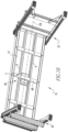
- first and second leg assemblies 20, 22 are essentially in parallel with the platform 12, the apparatus 10 is in a folded state, as shown in figure 6 .
- the apparatus 10 When the first and second leg assemblies 20, 22 are essentially perpendicular to the platform 12, the apparatus 10 is in a use state and the user is able to stand on the platform 12 and be supported by the first and second leg assemblies, as shown in figure 1 .
- the apparatus 10 When the apparatus 10 is in the use state, the user is able to pick up the apparatus 10 by the handle 2 with only one of the hands without tipping the apparatus 10.
- the handle 2 may be disposed in the platform 12.
- the handle 2 may have a first slot 24 and a second slot 26 adjacent the first slot 24, as shown in figure 3 .
- the first and second slots 24, 26 are disposed essentially in the platform's middle 28.
- the handle 2 may have a centerline 30 and a center of gravity, and the first slot 24 is disposed on a first side 32 of the centerline 30 and above the platform's center of gravity and the second slot 26 is disposed on a second side 34 of the centerline 30 and above the platform's center of gravity.
- Each slot may extend through the platform 12 from the platform's top 36 to the platform bottom 38, as shown in figures 3 , 4 and 5 .
- Each slot may have a first elongate side 40 and a second elongate side 42 essentially in parallel and spaced relation with the first elongate side 40, with each elongate side essentially in parallel with the centerline 30, as shown in figure 3 .
- each elongate side is essentially perpendicular with the centerline 30, as shown in figure 16 .
- Each slot may have an oval shape.
- the handle 2 may include a first insert 44 that fits in the first slot 24 and conforms with the oval shape of the first slot 24 and a second insert 46 that fits in the second slot 26 and conforms to the oval shape of the second slot 26.
- Each insert may have holes 5 through which fasteners 50 extend to hold the insert to the slot, as shown in figure 4 .
- the first and second leg assemblies 20, 22 each may be comprised of a first leg 52 and a second leg 54 in spaced relation and in parallel with the first leg 52, as shown in figure 1 .
- Each leg assembly may have a step 56 attached between the first and second legs 52, 54 on which the user can step to reach and stand on the platform 12 when the apparatus 10 is in the use state.
- the present invention pertains to an apparatus 10 on which a user with hands stands, as shown in figures 1 and 3 .
- the apparatus 10 comprises a platform 12 having a first end 14 and a second end 16 and a handle 2 disposed in the platform 12.
- the handle 2 has a first slot 24 and a second slot 26 adjacent the first slot 24.
- the first and second slots 24, 26 are disposed essentially in the platform's middle 28 and have an oval shape.
- the apparatus 10 comprises a support bar 6 attached to the platform's bottom 38 extending along the platform's centerline 30, as shown in figures 4 and 5 .
- the apparatus 10 comprises a first insert 44 disposed in the first slot 24 and attached to the support bar 6.
- the first insert 44 having a shape which conforms with the shape of the first slot 24.
- the apparatus 10 comprises a second insert 46 disposed in the second slot 26 and attached to the support bar 6.
- the second insert 46 has a shape which conforms with the shape of the second slot 26.
- the apparatus 10 comprises a first leg assembly 20 rotatably attached to the platform 12 in proximity to the first end 14.
- the apparatus 10 comprises a second leg assembly 22 rotatably attached to the platform 12 in proximity to the second end 16.
- the apparatus 10 is in a folded state, as shown in figure 6 .
- the apparatus 10 is in a use state and the user is able to stand on the platform 12 and be supported by the first and second leg assemblies, as shown in figure 1 .
- the apparatus 10 is in the use state, the user is able to pick up the apparatus 10 by the handle 2 with only one of the hands without tipping the apparatus 10.
- the present invention pertains to a method for a user with hands to stand on an apparatus 10.
- the method comprises the steps of placing the apparatus 10 that is in a use state in a desired location.
- the apparatus 10 comprises a platform 12 having a first end 14 and a second end 16 and a handle 2; a first leg assembly 20 rotatably attached to the platform 12 in proximity to the first end 14, a second leg assembly 22 rotatably attached to the platform 12 in proximity to the second end 16, when the first and second leg assemblies are essentially in parallel with the platform 12, the apparatus 10 is in a folded state, when the first and on leg assemblies are essentially perpendicular to the platform 12, the apparatus 10 is in a use state and the user is able to stand on the platform 12 and be supported by the first and second leg assemblies, when the apparatus 10 is in the use state, the user is able to pick up the apparatus 10 by the handle 2 with only one of the hands without tipping the apparatus 10.
- Each handle 2 insert has a first flange 60 and a second flange 62 that forms an angle, preferably about 90°, as shown in figures 7 and 8 , with the first flange 60.
- the first flange 60 and second flange 62 together form an L shape.
- the second flange 62 has holes 5 that align with holes 5 in a support bar 6, as shown in figures 4 and 5 .
- the support bar 6 extends along the centerline 30 of the platform 12 and is attached to the bottom 38 of the platform 12. Each end of the support bar 6 rests on a lip 64 of an end flange 66 at each end of the platform 12.
- the support bar 6 By resting on a lip 64 of an end flange 66 at each end of the platform 12, the support bar 6 is supported by the leg assemblies which extend down from the end flanges 66.
- the support bar 6 provides support and strength to the platform 12.
- the end of each crossbar is on the lip 64 of a side flange 70 of the platform 12 on each long side of the platform 12.
- the crossbars 68 add even further strength and support to the platform 12.
- the first flange 60 has a first section 72 that extends from the second flange 62 and a second section 74 that has an oval shaped opening, as shown in figures 7 and 8 that fits into and corresponds with the oval shaped opening in the platform 12 of the slot.
- the oval shaped opening in the second section 74 has a ridge 76 extending from the surface of the second section 74 along the perimeter of the oval shaped opening.
- a hinge 78 at each corner of the platform 12 attaches the leg assemblies to the platform 12.
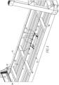
- Fig. 1 shows a perspective view of a work platform 12 with the legs 52, 54 extended and ready for use.
- the legs 52, 54 are designed to fold up under the platform 12 to allow for convenient storage of the work platform 12 when not in use.
- One possible form of handle 2 is shown.
- Fig. 2 shows a top view of the work platform 12, with dimensions regarding the slot positions relative to each other and the platform.
- the handle 2 is formed by having slots 24, 26 in the work platform decking 57.
- the slots are located in the center of the work platform 12 above its center of gravity. These slots are sized to conform to the dimensions of a user's fingers.
- the slots are symmetric so as to be for use with either hand.
- Fig. 3 shows a close up view of the handle 2 construction details.
- Handle inserts 44, 46 are located in the slots. These inserts insure that any potentially rough edges remaining after slots are formed in the work platform 12 decking are covered up. These inserts also provide a deeper gripping surface for the comfort of the user.
- the inserts could be made of molded plastic.
- Fig. 4 shows the underside of the work platform 12 and details of how the inserts 44, 46 might be attached. Holes 5 in the inserts and the central support bar 6 allow for the use of screws or pop rivets, etc.
- Figures 9-11 are overhead, side and underneath views, respectively, of a handle insert with dimensions of a preferred embodiment.
- the dimensions of the insert may me changed depending on the loads and size of the apparatus 10.
- the apparatus 10 is carried by the user to a desired location, where the user unfolds each leg assembly until each leg assembly extends essentially perpendicularly from the platform 12, and is now in the use state.
- the operation of the hinges and the leg assemblies is well known with work platforms.
- the user will then stand on the work platform 12 in conduct whatever actions are necessary.
- the user desires to move the work platform 12 to another location, but does not want to have to fold the work platform 12 up to the folded state, and wants to have use of a hand to be free to hold an object while the user lifts and moves the work platform 12 in the use state
- the user with one hand inserts a sum in the first slot 24 and the four fingers in the second slot 26 and grabs the portion of the platform 12 that is disposed between the first slot 24 and the second slot 26.
- the work platform 12 would not tip since the handle 2 is in the center of the platform 12, and by lifting up the platform 12 basically straight up, with the weight of the platform 12 evenly distributed around the handle 2, there is no unbalanced side that would otherwise cause the platform 12 to tip as it is left and.
- objects on the work platform 12, such as paint cans, or hands with putty or oils can stay in place on the work platform 12 while it is being moved, without having to be removed from the platform 12 are closed up.
- the disclosed handle 2 satisfies the need for a means by which a user can grasp, lift, and move a work platform 12 with one hand while maintaining the work platform 12 in an upright position.
- the handle 2 described is only one of many possible ways to accomplish the goals of this invention. According to embodiments not covered by the present invention the handle could include having straps or handles similar to those used on brief cases or suit cases which are attached to the deck of the work platform 12. These handles could be made to stow flush with the upper surface of the work platform 12 when not needed.
- the apparatus provides means for a user to pick up a work platform with one hand while allowing the work platform to remain in a generally level orientation.
- the apparatus 10 may be a Werner AP-30 work platform, modified to include a handle 2, which has a duty rating or 1 and able to support at least 250 pounds of load.
- the apparatus 10 can support greater loads, such as at least 500 pounds if so desired, with the platform and leg assemblies made thicker in material to support the increased load.
- the handle 2 alternatively is a strap 89 that is attached to the platform 12 at its middle 28 in a longitudinal relationship with the centerline 33 and at the balance point 91 of the apparatus 10.
- the strap 89 has an elongate portion 93 in spaced relationship with the platform 12 which a user grabs to lift the apparatus 10, and opposing connection portions 95 which extend down from the elongate portion 93 of the strap 89 and wrap around the center decking 97 of the platform 12 to attach the strap 89 to the platform 12.
- the opposing connection portions 95 split and form a loop around the center decking 97 to attach the strap 89 to the platform 12.
- the strap 89 is between . 5 inches thick and 3 inches thick and can be made out of cloth, plastic or metal.
- the elongate portion 93 can have chamfered or rounded edges so it is comfortable for the user to grab and limits any rubbing, cutting or pressure points to the user's hand.
- the present invention pertains to an apparatus 10 on which a user with hands stands.
- the apparatus 10 comprises a platform 12 having a length, a width, a first end 14 and a second end 16, a handle 2, a centerline 30 in parallel with the length and a center of gravity, the length longer than the width.
- the apparatus 10 comprises a first leg assembly 20 rotatably attached to the platform 12 in proximity to the first end.
- the apparatus 10 comprises a second leg assembly 22 rotatably attached to the platform 12 in proximity to the second end 16. When the first and second leg assemblies are essentially in parallel with the platform 12, the apparatus 10 is in a folded state.
- the apparatus 10 When the first and on leg assemblies are essentially perpendicular to the platform 12, the apparatus 10 is in a use state and the user is able to stand on the platform 12 and be supported by the first and second leg assemblies. When the apparatus 10 is in the use state, the user is able to pick up the apparatus 10 by the handle 2 with only one of the hands without tipping the apparatus 10.
- the handle 2 is disposed in the platform 12.
- the handle 2 has a first slot 24 and a second slot 26 adjacent the first slot 24.
- the first and second slots 24, 26 are disposed essentially in the platform's 12 middle 28.
- Each slot has a first elongate side and a second elongate side essentially in parallel and spaced relation with the first elongate side, with each elongate side essentially perpendicular with the centerline 30.
- Each slot may extend through the platform 12 from the platform's top to the platform 12 bottom. Each slot may have an oval shape.
- the first slot 24 and the second slot 26 may be disposed in an attachment 102 that fits into an opening 108 in the platform 12.
- the first and second leg assembly 22 each may comprise a first leg and a second leg in spaced relation and in parallel with the first leg. Each leg assembly may have a step attached between the first and second legs on which the user and step to reach and stand on the platform 12 when the apparatus 10 is in the use state.
- the present invention pertains to an apparatus 10 on which a user with hands stands.
- the apparatus 10 comprises a platform 12 having a length, a width, a first end 14 and a second end 16, a centerline 30 in parallel with the length and a handle 2 disposed in the platform 12.
- the handle 2 has a first slot 24 and a second slot 26 adjacent the first slot 24.
- the first and second slots 24, 26 disposed essentially in the platform's middle 28 and each having an oval shape.
- the apparatus 10 comprises a support bar 6 attached to the platform's bottom extending parallel to the platform's centerline 30.
- the apparatus 10 comprises a crossbar 68 attached to the platform's bottom extending perpendicular to the platform's centerline 30.
- the first slot 24 is on a right side 104 of the crossbar 68.
- the second slot 26 is on a left side 106 of the crossbar 68.
- the apparatus 10 comprises a first leg assembly 20 rotatably attached to the platform 12 in proximity to the first end 14.
- the apparatus 10 comprises a second leg assembly 22 rotatably attached to the platform 12 in proximity to the second end 16.
- the apparatus 10 is in a folded state.
- the apparatus 10 is in a use state and the user is able to stand on the platform 12 and be supported by the first and second leg assemblies.
- the apparatus 10 is in the use state, the user is able to pick up the apparatus 10 by the handle 2 with only one of the hands without tipping the apparatus 10.
- the present invention pertains to a method for a user with hands to stand on an apparatus 10.
- the method comprises the steps of placing the apparatus 10 that is in a use state in a desired location.
- the apparatus 10 comprises a platform 12 having a length, a width, a first end 14 and a second end 16 and a handle 2; a first leg assembly 20 rotatably attached to the platform 12 in proximity to the first end 14, a second leg assembly 22 rotatably attached to the platform 12 in proximity to the second end 16.
- the apparatus 10 is in a folded state.
- the apparatus 10 When the first and on leg assemblies are essentially perpendicular to the platform 12, the apparatus 10 is in a use state and the user is able to stand on the platform 12 and be supported by the first and second leg assemblies. When the apparatus 10 is in the use state, the user is able to pick up the apparatus 10 by the handle 2 with only one of the hands without tipping the apparatus 10.
- the handle 2 is disposed in the platform 12.
- the handle 2 has a first slot 24 and a second slot 26 adjacent the first slot 24.
- the first and second slots 24, 26 are disposed essentially in the platform's middle 28, each slot has a first elongate side and a second elongate side essentially in parallel and spaced relation with the first elongate side, with each elongate side essentially perpendicular with the centerline 30.
- the handle 2 is positioned into the platform 12 through a single opening 108 in the surface of the platform 12 which is filled with an attachment 102 that is a piece of plastic that has the first and second slots 24, 26.
- FIGS. 17 and 18 there are two support bars 6 extending in parallel along the length of the platform 12 and under the platform 12.
- the opening 108 in the platform 12 is between these two support bars 6.
- the attachment 102 fits into this opening 108 so the top surface of the attachment 102 is flush and smooth with the top surface of the platform 12. This way, there is nothing sticking up that a user can catch on or trip over when standing on the platform 12 on or about the handle 2. Screws, rivets, or bolts are used to attach the attachment 102 to the support bars 6.
- the attachment 102 has a handle 2 flange along its top surface and about its perimeter that fits onto the support bars 6, and through which the fasteners 50, such as bolts, rivets or screws are inserted to permanently fix the handle 2 to the platform 12.
- the crossbar 68 is disposed under the two support bars 6 and positioned perpendicularly thereto and is riveted with fasteners 50, such as rivets or bolts to the support bars 6.
- fasteners 50 such as rivets or bolts to the support bars 6.
- Each end of the crossbar 68 rests on a side flange 70 on each side of the platform 12 and is bolted or riveted with fasteners 50, such as bolts or rivets to the side flanges 70.
- Each slot of the attachment 102 is oval shaped and is formed from a first wall 112, a second wall 114, a third wall 116 and a fourth wall 118 extending down from the handle 2 flange.
- the first wall 112 is in parallel and spaced relation with the second wall 114 and the third wall 116 is in parallel and spaced relation with the fourth wall 118.
- the first wall 112 is connected with the third wall 116 and the fourth wall 118, and the second wall 114 is connected with the third wall 116 and the fourth wall 118.
- the walls extend down from the handle 2 flange a distance less than the distance the sidebars extend down from the platform 12 and not as far as the distance the crossbar 68 is below the platform 12.
- the first slot 24 and the second slot 26 are spaced apart about the same distance as the width of the crossbar 68 so the user can fit his hand through the first and second slots 24, 26 and grab the crossbar 68.
- the attachment 102 has a center portion 120 disposed between the first and second slots 24, 26.
- the first insert 44 has a first tab 154 located at a first end of the first insert 44 and a second tab 156 located at a second end of the first insert 44 to hold the first insert 44 from lifting up out of the platform 12 when the handle 2 is grabbed by a user to lift the apparatus 10.
- the first insert 44 has a first rivet upset portion 150 extending outwards from the bottom of the first elongate side 40, and a second rivet upset portion 152 extending outwards from the bottom of the second elongate side 42. Each rivet upset portion receives a rivet that extends through the platform 12 from the top 36 of the platform to fix the first insert 44 to the platform 12 in the first slot 24.
- the tabs and the rivet upset portions are disposed on the bottom 38 of the platform 12 when the first insert 44 is in place so the top 36 of the platform 12 is essentially smooth and flat.
- the rivet upset portions have a curved or a bump shape.
- the second insert 46 in this embodiment is designed in the same way.
- the rivet upset portions may also be used with the attachment 102.
Landscapes
- Engineering & Computer Science (AREA)
- Architecture (AREA)
- Mechanical Engineering (AREA)
- Civil Engineering (AREA)
- Structural Engineering (AREA)
- Handcart (AREA)
- Purses, Travelling Bags, Baskets, Or Suitcases (AREA)
- Special Chairs (AREA)
- Rehabilitation Tools (AREA)
- Ladders (AREA)
- Steering Devices For Bicycles And Motorcycles (AREA)
- Toys (AREA)
- Walking Sticks, Umbrellas, And Fans (AREA)
- Motorcycle And Bicycle Frame (AREA)
Claims (9)
- Appareil (10) sur lequel un utilisateur possédant des mains peut se tenir debout, comprenant :une plateforme (12) présentant une première extrémité (14) et une seconde extrémité (16) et une poignée (2), la poignée (2) est disposée dans la plateforme (12), la poignée (2) présente une première fente (24) et une seconde fente (26) adjacente à la première fente (24), les première et seconde fentes (24, 26) étant disposées essentiellement au milieu (28) de la plateforme (12), la plateforme (12) présente une ligne centrale (30) et un centre de gravité, la première fente (24) est disposée sur un premier côté (32) de la ligne centrale (30) et au-dessus du centre de gravité de la plateforme (12) et la seconde fente (26) est disposée sur un second côté (34) de la ligne centrale (30) et au-dessus du centre de gravité de la plateforme (12), les fentes sont dimensionnées pour s'adapter aux dimensions des doigts d'un utilisateur et sont symétriques de manière à pouvoir être utilisées avec l'une ou l'autre main ;un premier ensemble pied (20) fixé de manière rotative à la plateforme (12) à proximité de la première extrémité (14) ; etun second ensemble pied (22) fixé de manière rotative à la plateforme (12) à proximité de la seconde extrémité (16), lorsque les premier et second ensembles pied (20, 22) sont essentiellement parallèles à la plateforme (12), l'appareil (10) est dans un état plié, lorsque les premier et second ensembles pied sont essentiellement perpendiculaires à la plateforme (12), l'appareil (10) est dans un état d'utilisation et l'utilisateur peut se tenir debout sur la plateforme (12) et être supporté par les premier et second ensembles pied (20, 22), lorsque l'appareil (10) est dans l'état d'utilisation, l'utilisateur peut saisir l'appareil (10) par la poignée (2) avec une seule main sans faire basculer l'appareil (10),caractérisé par des inserts de poignée (44, 46) en plastique moulé situés dans les fentes (24, 26), les inserts (44, 46) étant configurés pour couvrir un quelconque bord potentiellement rugueux restant après la formation des fentes dans le tamis de la plateforme de travail et pour fournir une surface de saisie plus profonde pour le confort de l'utilisateur, dans lequel l'appareil peut supporter au moins 250 lbs (113,4 kg) de charge.
- Appareil (10) selon la revendication 1 caractérisé par le fait que chaque fente présente un premier côté allongé (40) et un second côté allongé (42) essentiellement parallèle et espacé du premier côté allongé (40), avec chaque côté allongé essentiellement parallèle à la ligne centrale (30).
- Appareil (10) selon la revendication 1 ou 2 caractérisé par le fait que chaque fente présente une forme ovale.
- Appareil (10) selon la revendication 3 caractérisé par le fait que la poignée (2) comporte un premier insert (44) qui s'insère dans la première fente (24) et s'adapte à la forme ovale de la première fente (24) et un second insert (46) qui s'insère dans la seconde fente (26) et s'adapte à la forme ovale de la seconde fente (26).
- Appareil (10) selon la revendication 4 caractérisé par le fait que chaque insert présente des trous (5) à travers lesquels des attaches (50) s'étendent pour maintenir l'insert à la fente.
- Appareil (10) selon une quelconque revendication précédente caractérisé par le fait que les premier et second ensembles pied (22) comprennent chacun un premier pied (52) et un second pied (54) espacé et parallèle au premier pied (52).
- Appareil (10) selon la revendication 6 caractérisé par le fait que chaque ensemble pied présente une marche (56) fixée entre les premier et second pieds (52, 54) sur laquelle l'utilisateur peut marcher (56) pour atteindre et se tenir debout sur la plateforme (12) lorsque l'appareil (10) est dans l'état d'utilisation.
- Appareil (10) sur lequel un utilisateur possédant des mains peut se tenir debout comprenant :une plateforme (12) présentant une longueur, une largeur, une première extrémité (14) et une seconde extrémité (16), une poignée (2), une ligne centrale (30) parallèle à la longueur et un centre de gravité, la longueur étant plus longue que la largeur ;un premier ensemble pied (20) fixé de manière rotative à la plateforme (12) à proximité de la première extrémité ;un second ensemble pied (22) fixé de manière rotative à la plateforme (12) à proximité de la seconde extrémité (16), lorsque les premier et second ensembles pied sont essentiellement parallèles à la plateforme (12), l'appareil (10) est dans un état plié, lorsque les premier et second ensembles pied sont essentiellement perpendiculaires à la plateforme (12), l'appareil (10) est dans un état d'utilisation et l'utilisateur peut se tenir debout sur la plateforme (12) et être supporté par les premier et second ensembles pied, lorsque l'appareil (10) est dans l'état d'utilisation, l'utilisateur peut saisir l'appareil (10) par la poignée (2) avec une seule main sans faire basculer l'appareil (10), la poignée (2) est disposée dans la plateforme (12), la poignée (2) présente une première fente (24) et une seconde fente (26) adjacente à la première fente (24), les première et seconde fentes (24, 26) sont disposées essentiellement au milieu (28) de la plateforme (12), chaque fente présente un premier côté allongé et un second côté allongé essentiellement parallèle et espacé par rapport au premier côté allongé, chaque fente s'étend à travers la plateforme (12) depuis le haut de la plateforme jusqu'en bas de la plateforme, chaque fente présente une forme ovale,les premier et second ensembles pied (22) comprennent chacun un premier pied et un second pied espacé et parallèle au premier pied, chaque ensemble pied présente une marche fixée entre les premier et second pieds sur laquelle l'utilisateur marche pour atteindre et se tenir debout sur la plateforme (12) lorsque l'appareil (10) est en état d'utilisation,caractérisé par chaque côté allongé desdites fentes (24, 26) étant essentiellement perpendiculaire à la ligne centrale de ladite plateforme (12) ;dans lequel la première fente (24) et la seconde fente (26) sont disposées dans une fixation (102) qui s'insère dans une seule ouverture (108) dans la plateforme (12),dans lequel la poignée (2) est positionnée dans la plateforme (12) à travers la seule ouverture (108) dans la surface de la plateforme (12) qui est remplie de ladite fixation (102) qui est un morceau de plastique qui présente les première et seconde fentes (24, 26),dans lequelil y a une barre transversale (68) qui fait partie de la structure de la plateforme (12) qui n'est pas retirée et la poignée en plastique (2) comporte cette barre transversale (68) comme partie de la prise en main, lorsque l'utilisateur saisit la poignée (2), le pouce de la main de l'utilisateur s'étend à travers la première fente (24) et les doigts de la main de l'utilisateur s'étendent à travers la seconde fente (26), lorsque l'utilisateur forme une prise avec sa main, les doigts et le pouce s'enroulent autour de la barre transversale (68) sous les première et seconde fentes (24, 26) pour saisir l'appareil (10) et le soulever,dans lequel il y a deux barres de support (6) s'étendant parallèlement le long de la plateforme (12) et sous la plateforme (12), la seule ouverture (108) dans la plateforme (12) se trouve entre ces deux barres de support (6), la fixation (102) s'insère dans cette seule ouverture (108) de sorte que la surface supérieure de la fixation (102) est lisse et s'aligne avec la surface supérieure de la plateforme (12), de sorte qu'il n'y ait rien qui dépasse sur lequel un utilisateur puisse s'accrocher ou trébucher lorsqu'il se tient debout sur la plateforme (12) sur ou autour de la poignée (2), des vis, des rivets ou des boulons sont utilisés pour fixer la fixation (102) aux barres de support (6), la fixation (102) présente une bride de poignée le long de sa surface supérieure et autour de son périmètre qui s'adapte aux barres de support (6), et à travers laquelle les attaches (50), telles que des boulons, des rivets ou des vis, sont insérées pour fixer de manière permanente la poignée (2) à la plateforme (12), la barre transversale (68) est disposée sous les deux barres de support (6) et positionnée perpendiculairement à celles-ci et est rivetée avec des attaches (50), telles que des rivets ou des boulons aux barres de support (6), chaque extrémité de la barre transversale (68) repose sur une bride latérale (70) de chaque côté de la plateforme (12) et est boulonnée ou rivetée avec des attaches (50), telles que des boulons ou des rivets aux brides latérales (70), chaque fente de la fixation (102) est de forme ovale et est formé d'une première paroi (112), d'une deuxième paroi (114), d'une troisième paroi (116) et d'une quatrième paroi (118) s'étendant vers le bas depuis la bride de poignée, la première paroi (112) est parallèle à et espacée de la deuxième paroi (114) et la troisième paroi (116) est parallèle à et espacée de la quatrième paroi (118), la première paroi (112) est reliée à la troisième paroi (116) et à la quatrième paroi (118), et la deuxième paroi (114) est reliée à la troisième paroi (116) et à la quatrième paroi (118), les parois s'étendent vers le bas à partir de la bride de poignée sur une distance inférieure à la distance à laquelle les barres latérales s'étendent vers le bas à partir de la plateforme (12) et pas dans la mesure où la barre transversale (68) se trouve en dessous de la plateforme (12), la première fente (24) et la seconde fente (26) sont espacées d'environ la même distance que la largeur de la barre transversale (68) pour que l'utilisateur puisse insérer sa main dans les première et seconde fentes (24, 26) et saisir la barre transversale (68), la fixation (102) présente une partie centrale (120) disposée entre les première et seconde fentes (24, 26).
- Procédé permettant à un utilisateur possédant des mains de se tenir debout sur un appareil (10), comprenant les étapes suivantes :placer l'appareil (10) qui est dans un état d'utilisation dans un emplacement souhaité, l'appareil (10) comprenant une plateforme (12) présentant une première extrémité (14) et une seconde extrémité (16) et une poignée (2) ; un premier ensemble pied (20) fixé de manière rotative à la plateforme (12) à proximité de la première extrémité (14), un second ensemble pied (22) fixé de manière rotative à la plateforme (12) à proximité de la seconde extrémité (16), lorsque les premier et second ensembles pied (20, 22) sont essentiellement parallèles à la plateforme (12), l'appareil (10) est dans un état plié, lorsque les premier et second ensembles pied sont essentiellement perpendiculaires à la plateforme (12), l'appareil (10) est dans un état d'utilisation et l'utilisateur peut se tenir debout sur la plateforme (12) et être supporté par les premier et second ensembles pied (20, 22), lorsque l'appareil (10) est dans l'état d'utilisation, l'utilisateur peut saisir l'appareil (10) par la poignée (2) avec une seule main sans faire basculer l'appareil (10), la poignée (2) est disposée dans la plateforme (12), la poignée (2) présente une première fente (24) et une seconde fente (26) adjacente à la première fente (24), les première et seconde fentes (24, 26) étant disposées essentiellement au milieu (28) de la plateforme (12), la plateforme (12) présente une ligne centrale (30) et un centre de gravité, la première fente (24) est disposée sur un premier côté (32) de la ligne centrale (30) et au-dessus du centre de gravité de la plateforme (12) et la seconde fente (26) est disposée sur un second côté (34) de la ligne centrale (30) et au-dessus du centre de gravité de la plateforme (12), les fentes sont dimensionnées pour s'adapter aux dimensions des doigts d'un utilisateur et sont symétriques de manière à pouvoir être utilisées avec l'une ou l'autre main,caractérisé pardes inserts de poignée en plastique moulé (44, 46) étant situés dans les fentes, les inserts sont configurés pour couvrir un quelconque bord potentiellement rugueux restant après la formation des fentes dans le tamis de la plateforme de travail et pour fournir une surface de saisie plus profonde pour le confort de l'utilisateur ;ledit procédé comprenant en outre les étapes suivantes placer un objet sur la plateforme (12) ;saisir la poignée (2) dans la plateforme (12) pendant que l'appareil (10) est dans l'état d'utilisation ;soulever l'appareil (10) par la poignée (2) d'une main par l'utilisateur pendant que l'autre main de l'utilisateur est libre de sorte que l'appareil (10) ne bascule pas et que l'objet ne se détache pas de la plateforme (12) ; etreplacer l'appareil (10) sur le sol avec l'objet toujours sur la plateforme (12), l'appareil pouvant supporter au moins 250 lbs (113,4 kg) de charge.
Priority Applications (1)
| Application Number | Priority Date | Filing Date | Title |
|---|---|---|---|
| EP18160807.6A EP3372751A1 (fr) | 2017-03-10 | 2018-03-08 | Plateforme de travail et procédé |
Applications Claiming Priority (2)
| Application Number | Priority Date | Filing Date | Title |
|---|---|---|---|
| US15/077,489 US10815680B2 (en) | 2016-03-22 | 2016-03-22 | Apparatus having a handle on which a user stands, and method |
| US15/299,099 US10738487B2 (en) | 2016-03-22 | 2016-10-20 | Apparatus having a handle on which a user stands, and method |
Publications (2)
| Publication Number | Publication Date |
|---|---|
| EP3222797A1 EP3222797A1 (fr) | 2017-09-27 |
| EP3222797B1 true EP3222797B1 (fr) | 2024-08-07 |
Family
ID=58266950
Family Applications (1)
| Application Number | Title | Priority Date | Filing Date |
|---|---|---|---|
| EP17160284.0A Active EP3222797B1 (fr) | 2016-03-22 | 2017-03-10 | Appareil doté d'une poignée sur lequel l'utilisateur se tient debout et procédé |
Country Status (6)
| Country | Link |
|---|---|
| US (1) | US10738487B2 (fr) |
| EP (1) | EP3222797B1 (fr) |
| CN (2) | CN107217828B (fr) |
| AU (3) | AU2017200973A1 (fr) |
| CA (1) | CA2959296C (fr) |
| MX (3) | MX2025011975A (fr) |
Families Citing this family (8)
| Publication number | Priority date | Publication date | Assignee | Title |
|---|---|---|---|---|
| US10815680B2 (en) | 2016-03-22 | 2020-10-27 | Werner Co. | Apparatus having a handle on which a user stands, and method |
| CN207436473U (zh) * | 2017-08-04 | 2018-06-01 | 苏州飞华铝制工业有限公司 | 工作台梯柱的解锁结构 |
| US20190226217A1 (en) * | 2018-01-24 | 2019-07-25 | Tricam Industries, Inc. | Work platform |
| FR3096381B1 (fr) | 2019-05-24 | 2022-03-25 | Cdh Group | Systeme d’assemblage de plateformes sans outils |
| US12497789B2 (en) * | 2021-03-02 | 2025-12-16 | Werner Co. | Interlocking work platform system |
| US12565779B2 (en) | 2021-10-28 | 2026-03-03 | Werner Co. | Work platform and method |
| CN115370114A (zh) * | 2022-08-22 | 2022-11-22 | 库珀新能源股份有限公司 | 一种伸缩式施工凳梯 |
| US12096764B1 (en) * | 2023-08-18 | 2024-09-24 | Keene Outdoors, LLC | Deer stand with fork lift set up |
Citations (1)
| Publication number | Priority date | Publication date | Assignee | Title |
|---|---|---|---|---|
| US5462221A (en) * | 1995-01-04 | 1995-10-31 | Bradford Company | Tote box handle |
Family Cites Families (44)
| Publication number | Priority date | Publication date | Assignee | Title |
|---|---|---|---|---|
| US581727A (en) * | 1897-05-04 | Combination ironing-table | ||
| US2206314A (en) * | 1939-02-20 | 1940-07-02 | Willy W Werner | Box |
| US2771235A (en) * | 1949-07-11 | 1956-11-20 | Robert P Stephenson | Reinforced case |
| US2832648A (en) * | 1956-06-25 | 1958-04-29 | Herman W Goosmann | Trestles |
| US3848700A (en) * | 1973-06-26 | 1974-11-19 | T Davis | Supporting device |
| US4690248A (en) * | 1984-07-18 | 1987-09-01 | Killeen Walter H | Portable hoist |
| GB8811094D0 (en) * | 1988-05-11 | 1988-06-15 | Reed Packaging Ltd | Container |
| US4971201A (en) * | 1989-03-30 | 1990-11-20 | Sathre Robert C | Stacking rim for soft-sided containers |
| US4949649A (en) * | 1989-04-28 | 1990-08-21 | Sico Incorporated | Folding stages |
| US5332062A (en) * | 1991-03-12 | 1994-07-26 | Paul Revere | Simplified scaffold ladder |
| US5282519A (en) * | 1993-03-15 | 1994-02-01 | Venturo Frank J | Combined sawhorse and toolbox apparatus |
| US5746288A (en) * | 1996-08-29 | 1998-05-05 | O'neal; Diana | Walk board |
| DE19714431C2 (de) * | 1997-04-08 | 2002-03-28 | Horst Laug | Mehrzweck-Arbeitsdiele |
| GB2343883B (en) * | 1998-11-20 | 2002-05-29 | Linpac Mouldings Ltd | A plastics component for attachment to sheet material |
| US6017106A (en) * | 1999-02-02 | 2000-01-25 | Gateway 2000, Inc | Removable carry handle and adapter for portable computer |
| GB2358131A (en) * | 2000-01-11 | 2001-07-18 | Innovations For Trade And Tech | Step-stool |
| JP2001224439A (ja) * | 2000-02-18 | 2001-08-21 | Hasegawa Kogyo Co Ltd | 折畳み作業台 |
| WO2002016819A1 (fr) * | 2000-08-22 | 2002-02-28 | Keith David Virtue | Ensemble pieds pivotants |
| US6425520B1 (en) * | 2000-10-24 | 2002-07-30 | International Paper Company | Beverage carrier |
| JP3872274B2 (ja) * | 2000-10-24 | 2007-01-24 | ホリーエンジニアリング株式会社 | 可搬式作業台 |
| US6808105B2 (en) * | 2000-12-30 | 2004-10-26 | Dong-Jin Paper Board Box Co., Ltd. | Box for transportation |
| US20020162841A1 (en) * | 2001-05-01 | 2002-11-07 | Amos Shamir | Single action latch |
| JP2004323036A (ja) * | 2003-04-23 | 2004-11-18 | Toto Ltd | 輸送容器 |
| USD486243S1 (en) * | 2003-05-14 | 2004-02-03 | Alinco, Inc. | Footing platform assembly for working |
| US6902034B2 (en) * | 2003-05-28 | 2005-06-07 | Cosco Management, Inc. | Apparatus with utility tray mounted to scaffold |
| US6892860B2 (en) * | 2003-05-28 | 2005-05-17 | Cosco Management, Inc. | Scaffold with leg lock |
| US7516704B2 (en) * | 2004-01-13 | 2009-04-14 | Black & Decker Inc. | Paint station |
| US7210560B2 (en) * | 2004-03-26 | 2007-05-01 | Brink Daniel J | Folding platform structure |
| JP4098280B2 (ja) | 2004-07-07 | 2008-06-11 | アルインコ株式会社 | 可搬式作業台 |
| KR100714992B1 (ko) * | 2004-12-22 | 2007-05-09 | 임정환 | 절첩식 작업대 |
| US20090123736A1 (en) * | 2005-06-21 | 2009-05-14 | Green Terrell J | Repulpable packaging materials with reinforcement |
| EP1788167A1 (fr) * | 2005-11-18 | 2007-05-23 | Telesteps AB | Plate-forme repliable |
| CN2908669Y (zh) * | 2006-03-20 | 2007-06-06 | 碧卡株式会社 | 便携式操作台 |
| US7797982B2 (en) * | 2006-05-08 | 2010-09-21 | Resource Management International, Llc | Personal breathalyzer having digital circuitry |
| US20090078165A1 (en) * | 2007-09-24 | 2009-03-26 | Yi-Chun Tseng | Multi-function worktable |
| US20100071996A1 (en) * | 2008-09-24 | 2010-03-25 | Wen-Hung Huang | Collapsible platform ladder |
| WO2010129703A2 (fr) * | 2009-05-05 | 2010-11-11 | Wing Enterprises, Incorporated | Echelles, composants d'échelles, accessoires d'échelles, systèmes d'échelles et procédés correspondants |
| US8381873B2 (en) | 2009-07-28 | 2013-02-26 | Affinity Tool Works | Ladder and support stand |
| US8777683B2 (en) * | 2010-10-18 | 2014-07-15 | Matthew J. Friedman | Self-cleansing retractable handle assembly for water craft |
| CN103569460A (zh) * | 2013-10-24 | 2014-02-12 | 青岛海信电器股份有限公司 | 一种塑料扣手以及包装箱 |
| US20150267469A1 (en) * | 2014-03-21 | 2015-09-24 | Joe Markusen | Ladder Plank |
| US9120218B1 (en) * | 2014-05-05 | 2015-09-01 | Robert Arnold Stehlik | Standup paddle board grip handle |
| CN205046823U (zh) * | 2015-08-13 | 2016-02-24 | 唐绪福 | 便携式家装施工脚手架 |
| USD776826S1 (en) * | 2015-08-13 | 2017-01-17 | Tricam Industries, Inc. | Work platform |
-
2016
- 2016-10-20 US US15/299,099 patent/US10738487B2/en active Active
-
2017
- 2017-02-13 AU AU2017200973A patent/AU2017200973A1/en not_active Abandoned
- 2017-02-28 CA CA2959296A patent/CA2959296C/fr active Active
- 2017-03-10 EP EP17160284.0A patent/EP3222797B1/fr active Active
- 2017-03-14 MX MX2025011975A patent/MX2025011975A/es unknown
- 2017-03-14 MX MX2017003349A patent/MX385145B/es unknown
- 2017-03-14 MX MX2021009470A patent/MX2021009470A/es unknown
- 2017-03-20 CN CN201710165927.4A patent/CN107217828B/zh active Active
- 2017-03-20 CN CN202110321882.1A patent/CN113047590B/zh active Active
-
2019
- 2019-01-23 AU AU2019200447A patent/AU2019200447B2/en active Active
-
2021
- 2021-04-26 AU AU2021202564A patent/AU2021202564B2/en active Active
Patent Citations (1)
| Publication number | Priority date | Publication date | Assignee | Title |
|---|---|---|---|---|
| US5462221A (en) * | 1995-01-04 | 1995-10-31 | Bradford Company | Tote box handle |
Also Published As
| Publication number | Publication date |
|---|---|
| MX2021009470A (es) | 2021-11-17 |
| CA2959296C (fr) | 2019-06-11 |
| US10738487B2 (en) | 2020-08-11 |
| CA2959296A1 (fr) | 2017-09-22 |
| CN107217828A (zh) | 2017-09-29 |
| CN113047590B (zh) | 2023-07-18 |
| AU2019200447A1 (en) | 2019-02-14 |
| EP3222797A1 (fr) | 2017-09-27 |
| MX385145B (es) | 2025-03-14 |
| US20170275900A1 (en) | 2017-09-28 |
| MX2025011975A (es) | 2025-11-03 |
| AU2019200447B2 (en) | 2021-01-28 |
| CN113047590A (zh) | 2021-06-29 |
| MX2017003349A (es) | 2018-08-15 |
| AU2021202564B2 (en) | 2023-05-11 |
| AU2021202564A1 (en) | 2021-05-27 |
| AU2017200973A1 (en) | 2017-10-12 |
| CN107217828B (zh) | 2021-04-23 |
Similar Documents
| Publication | Publication Date | Title |
|---|---|---|
| AU2021202564B2 (en) | Apparatus Having a Handle on Which a User Stands, and Method | |
| US10858848B2 (en) | Work platform and method | |
| US12060717B2 (en) | Platform with handle | |
| AU2022202581B2 (en) | Work platform and method | |
| US20220178153A1 (en) | Work Platform and Method | |
| US20240392627A1 (en) | Stepladder tray | |
| US8997930B2 (en) | Ladders, ladder components, ladder accessories, ladder systems and related methods | |
| US10718120B1 (en) | Scaffold tool bucket holder | |
| US20160024844A1 (en) | Safety ladder and work platform for helicopter and aircraft maintenence | |
| EP3290630A1 (fr) | Escabeau hybride et procédé | |
| US5123620A (en) | Accessory container for ladder | |
| US20180179817A1 (en) | Portable ladder and rolling shaft | |
| US20140110410A1 (en) | Device and method for securing tools above ground | |
| US20040163891A1 (en) | Stepladder accessory tray | |
| US20250162851A1 (en) | Storage Tote Lifting Device | |
| US20150023615A1 (en) | Mountable holding bag for an extension ladder stabilizer | |
| ITVR970020A1 (it) | Carrello saliscale con ruote rialzabili o staccabili o riposizionabili e posizionabili sopra l'altezza del gradino o in altro luogo a doppie | |
| WO2017066419A1 (fr) | Système de contenant à usages multiples |
Legal Events
| Date | Code | Title | Description |
|---|---|---|---|
| PUAI | Public reference made under article 153(3) epc to a published international application that has entered the european phase |
Free format text: ORIGINAL CODE: 0009012 |
|
| STAA | Information on the status of an ep patent application or granted ep patent |
Free format text: STATUS: THE APPLICATION HAS BEEN PUBLISHED |
|
| AK | Designated contracting states |
Kind code of ref document: A1 Designated state(s): AL AT BE BG CH CY CZ DE DK EE ES FI FR GB GR HR HU IE IS IT LI LT LU LV MC MK MT NL NO PL PT RO RS SE SI SK SM TR |
|
| AX | Request for extension of the european patent |
Extension state: BA ME |
|
| STAA | Information on the status of an ep patent application or granted ep patent |
Free format text: STATUS: REQUEST FOR EXAMINATION WAS MADE |
|
| 17P | Request for examination filed |
Effective date: 20180326 |
|
| RBV | Designated contracting states (corrected) |
Designated state(s): AL AT BE BG CH CY CZ DE DK EE ES FI FR GB GR HR HU IE IS IT LI LT LU LV MC MK MT NL NO PL PT RO RS SE SI SK SM TR |
|
| STAA | Information on the status of an ep patent application or granted ep patent |
Free format text: STATUS: EXAMINATION IS IN PROGRESS |
|
| 17Q | First examination report despatched |
Effective date: 20210210 |
|
| GRAP | Despatch of communication of intention to grant a patent |
Free format text: ORIGINAL CODE: EPIDOSNIGR1 |
|
| STAA | Information on the status of an ep patent application or granted ep patent |
Free format text: STATUS: GRANT OF PATENT IS INTENDED |
|
| RIC1 | Information provided on ipc code assigned before grant |
Ipc: E04G 1/30 20060101ALN20240307BHEP Ipc: E06C 7/00 20060101ALI20240307BHEP Ipc: E06C 1/39 20060101ALI20240307BHEP Ipc: E04G 1/34 20060101AFI20240307BHEP |
|
| RIC1 | Information provided on ipc code assigned before grant |
Ipc: E04G 1/30 20060101ALN20240319BHEP Ipc: E06C 7/00 20060101ALI20240319BHEP Ipc: E06C 1/39 20060101ALI20240319BHEP Ipc: E04G 1/34 20060101AFI20240319BHEP |
|
| INTG | Intention to grant announced |
Effective date: 20240404 |
|
| GRAS | Grant fee paid |
Free format text: ORIGINAL CODE: EPIDOSNIGR3 |
|
| GRAA | (expected) grant |
Free format text: ORIGINAL CODE: 0009210 |
|
| STAA | Information on the status of an ep patent application or granted ep patent |
Free format text: STATUS: THE PATENT HAS BEEN GRANTED |
|
| AK | Designated contracting states |
Kind code of ref document: B1 Designated state(s): AL AT BE BG CH CY CZ DE DK EE ES FI FR GB GR HR HU IE IS IT LI LT LU LV MC MK MT NL NO PL PT RO RS SE SI SK SM TR |
|
| REG | Reference to a national code |
Ref country code: GB Ref legal event code: FG4D |
|
| REG | Reference to a national code |
Ref country code: CH Ref legal event code: EP |
|
| REG | Reference to a national code |
Ref country code: IE Ref legal event code: FG4D |
|
| REG | Reference to a national code |
Ref country code: DE Ref legal event code: R096 Ref document number: 602017083830 Country of ref document: DE |
|
| REG | Reference to a national code |
Ref country code: LT Ref legal event code: MG9D |
|
| REG | Reference to a national code |
Ref country code: NL Ref legal event code: MP Effective date: 20240807 |
|
| PG25 | Lapsed in a contracting state [announced via postgrant information from national office to epo] |
Ref country code: NO Free format text: LAPSE BECAUSE OF FAILURE TO SUBMIT A TRANSLATION OF THE DESCRIPTION OR TO PAY THE FEE WITHIN THE PRESCRIBED TIME-LIMIT Effective date: 20241107 |
|
| REG | Reference to a national code |
Ref country code: AT Ref legal event code: MK05 Ref document number: 1711085 Country of ref document: AT Kind code of ref document: T Effective date: 20240807 |
|
| PG25 | Lapsed in a contracting state [announced via postgrant information from national office to epo] |
Ref country code: PL Free format text: LAPSE BECAUSE OF FAILURE TO SUBMIT A TRANSLATION OF THE DESCRIPTION OR TO PAY THE FEE WITHIN THE PRESCRIBED TIME-LIMIT Effective date: 20240807 Ref country code: FI Free format text: LAPSE BECAUSE OF FAILURE TO SUBMIT A TRANSLATION OF THE DESCRIPTION OR TO PAY THE FEE WITHIN THE PRESCRIBED TIME-LIMIT Effective date: 20240807 Ref country code: NL Free format text: LAPSE BECAUSE OF FAILURE TO SUBMIT A TRANSLATION OF THE DESCRIPTION OR TO PAY THE FEE WITHIN THE PRESCRIBED TIME-LIMIT Effective date: 20240807 Ref country code: PT Free format text: LAPSE BECAUSE OF FAILURE TO SUBMIT A TRANSLATION OF THE DESCRIPTION OR TO PAY THE FEE WITHIN THE PRESCRIBED TIME-LIMIT Effective date: 20241209 Ref country code: GR Free format text: LAPSE BECAUSE OF FAILURE TO SUBMIT A TRANSLATION OF THE DESCRIPTION OR TO PAY THE FEE WITHIN THE PRESCRIBED TIME-LIMIT Effective date: 20241108 |
|
| PG25 | Lapsed in a contracting state [announced via postgrant information from national office to epo] |
Ref country code: BG Free format text: LAPSE BECAUSE OF FAILURE TO SUBMIT A TRANSLATION OF THE DESCRIPTION OR TO PAY THE FEE WITHIN THE PRESCRIBED TIME-LIMIT Effective date: 20240807 |
|
| PG25 | Lapsed in a contracting state [announced via postgrant information from national office to epo] |
Ref country code: LV Free format text: LAPSE BECAUSE OF FAILURE TO SUBMIT A TRANSLATION OF THE DESCRIPTION OR TO PAY THE FEE WITHIN THE PRESCRIBED TIME-LIMIT Effective date: 20240807 |
|
| PG25 | Lapsed in a contracting state [announced via postgrant information from national office to epo] |
Ref country code: AT Free format text: LAPSE BECAUSE OF FAILURE TO SUBMIT A TRANSLATION OF THE DESCRIPTION OR TO PAY THE FEE WITHIN THE PRESCRIBED TIME-LIMIT Effective date: 20240807 Ref country code: IS Free format text: LAPSE BECAUSE OF FAILURE TO SUBMIT A TRANSLATION OF THE DESCRIPTION OR TO PAY THE FEE WITHIN THE PRESCRIBED TIME-LIMIT Effective date: 20241207 |
|
| PG25 | Lapsed in a contracting state [announced via postgrant information from national office to epo] |
Ref country code: HR Free format text: LAPSE BECAUSE OF FAILURE TO SUBMIT A TRANSLATION OF THE DESCRIPTION OR TO PAY THE FEE WITHIN THE PRESCRIBED TIME-LIMIT Effective date: 20240807 |
|
| PG25 | Lapsed in a contracting state [announced via postgrant information from national office to epo] |
Ref country code: ES Free format text: LAPSE BECAUSE OF FAILURE TO SUBMIT A TRANSLATION OF THE DESCRIPTION OR TO PAY THE FEE WITHIN THE PRESCRIBED TIME-LIMIT Effective date: 20240807 Ref country code: RS Free format text: LAPSE BECAUSE OF FAILURE TO SUBMIT A TRANSLATION OF THE DESCRIPTION OR TO PAY THE FEE WITHIN THE PRESCRIBED TIME-LIMIT Effective date: 20241107 |
|
| PG25 | Lapsed in a contracting state [announced via postgrant information from national office to epo] |
Ref country code: RS Free format text: LAPSE BECAUSE OF FAILURE TO SUBMIT A TRANSLATION OF THE DESCRIPTION OR TO PAY THE FEE WITHIN THE PRESCRIBED TIME-LIMIT Effective date: 20241107 Ref country code: PT Free format text: LAPSE BECAUSE OF FAILURE TO SUBMIT A TRANSLATION OF THE DESCRIPTION OR TO PAY THE FEE WITHIN THE PRESCRIBED TIME-LIMIT Effective date: 20241209 Ref country code: PL Free format text: LAPSE BECAUSE OF FAILURE TO SUBMIT A TRANSLATION OF THE DESCRIPTION OR TO PAY THE FEE WITHIN THE PRESCRIBED TIME-LIMIT Effective date: 20240807 Ref country code: NO Free format text: LAPSE BECAUSE OF FAILURE TO SUBMIT A TRANSLATION OF THE DESCRIPTION OR TO PAY THE FEE WITHIN THE PRESCRIBED TIME-LIMIT Effective date: 20241107 Ref country code: NL Free format text: LAPSE BECAUSE OF FAILURE TO SUBMIT A TRANSLATION OF THE DESCRIPTION OR TO PAY THE FEE WITHIN THE PRESCRIBED TIME-LIMIT Effective date: 20240807 Ref country code: LV Free format text: LAPSE BECAUSE OF FAILURE TO SUBMIT A TRANSLATION OF THE DESCRIPTION OR TO PAY THE FEE WITHIN THE PRESCRIBED TIME-LIMIT Effective date: 20240807 Ref country code: IS Free format text: LAPSE BECAUSE OF FAILURE TO SUBMIT A TRANSLATION OF THE DESCRIPTION OR TO PAY THE FEE WITHIN THE PRESCRIBED TIME-LIMIT Effective date: 20241207 Ref country code: HR Free format text: LAPSE BECAUSE OF FAILURE TO SUBMIT A TRANSLATION OF THE DESCRIPTION OR TO PAY THE FEE WITHIN THE PRESCRIBED TIME-LIMIT Effective date: 20240807 Ref country code: GR Free format text: LAPSE BECAUSE OF FAILURE TO SUBMIT A TRANSLATION OF THE DESCRIPTION OR TO PAY THE FEE WITHIN THE PRESCRIBED TIME-LIMIT Effective date: 20241108 Ref country code: FI Free format text: LAPSE BECAUSE OF FAILURE TO SUBMIT A TRANSLATION OF THE DESCRIPTION OR TO PAY THE FEE WITHIN THE PRESCRIBED TIME-LIMIT Effective date: 20240807 Ref country code: ES Free format text: LAPSE BECAUSE OF FAILURE TO SUBMIT A TRANSLATION OF THE DESCRIPTION OR TO PAY THE FEE WITHIN THE PRESCRIBED TIME-LIMIT Effective date: 20240807 Ref country code: BG Free format text: LAPSE BECAUSE OF FAILURE TO SUBMIT A TRANSLATION OF THE DESCRIPTION OR TO PAY THE FEE WITHIN THE PRESCRIBED TIME-LIMIT Effective date: 20240807 Ref country code: AT Free format text: LAPSE BECAUSE OF FAILURE TO SUBMIT A TRANSLATION OF THE DESCRIPTION OR TO PAY THE FEE WITHIN THE PRESCRIBED TIME-LIMIT Effective date: 20240807 |
|
| PG25 | Lapsed in a contracting state [announced via postgrant information from national office to epo] |
Ref country code: SM Free format text: LAPSE BECAUSE OF FAILURE TO SUBMIT A TRANSLATION OF THE DESCRIPTION OR TO PAY THE FEE WITHIN THE PRESCRIBED TIME-LIMIT Effective date: 20240807 Ref country code: RO Free format text: LAPSE BECAUSE OF FAILURE TO SUBMIT A TRANSLATION OF THE DESCRIPTION OR TO PAY THE FEE WITHIN THE PRESCRIBED TIME-LIMIT Effective date: 20240807 Ref country code: DK Free format text: LAPSE BECAUSE OF FAILURE TO SUBMIT A TRANSLATION OF THE DESCRIPTION OR TO PAY THE FEE WITHIN THE PRESCRIBED TIME-LIMIT Effective date: 20240807 |
|
| PG25 | Lapsed in a contracting state [announced via postgrant information from national office to epo] |
Ref country code: EE Free format text: LAPSE BECAUSE OF FAILURE TO SUBMIT A TRANSLATION OF THE DESCRIPTION OR TO PAY THE FEE WITHIN THE PRESCRIBED TIME-LIMIT Effective date: 20240807 |
|
| PG25 | Lapsed in a contracting state [announced via postgrant information from national office to epo] |
Ref country code: CZ Free format text: LAPSE BECAUSE OF FAILURE TO SUBMIT A TRANSLATION OF THE DESCRIPTION OR TO PAY THE FEE WITHIN THE PRESCRIBED TIME-LIMIT Effective date: 20240807 |
|
| PG25 | Lapsed in a contracting state [announced via postgrant information from national office to epo] |
Ref country code: SK Free format text: LAPSE BECAUSE OF FAILURE TO SUBMIT A TRANSLATION OF THE DESCRIPTION OR TO PAY THE FEE WITHIN THE PRESCRIBED TIME-LIMIT Effective date: 20240807 |
|
| REG | Reference to a national code |
Ref country code: DE Ref legal event code: R097 Ref document number: 602017083830 Country of ref document: DE |
|
| PLBE | No opposition filed within time limit |
Free format text: ORIGINAL CODE: 0009261 |
|
| STAA | Information on the status of an ep patent application or granted ep patent |
Free format text: STATUS: NO OPPOSITION FILED WITHIN TIME LIMIT |
|
| 26N | No opposition filed |
Effective date: 20250508 |
|
| PG25 | Lapsed in a contracting state [announced via postgrant information from national office to epo] |
Ref country code: SE Free format text: LAPSE BECAUSE OF FAILURE TO SUBMIT A TRANSLATION OF THE DESCRIPTION OR TO PAY THE FEE WITHIN THE PRESCRIBED TIME-LIMIT Effective date: 20240807 |
|
| PG25 | Lapsed in a contracting state [announced via postgrant information from national office to epo] |
Ref country code: MC Free format text: LAPSE BECAUSE OF FAILURE TO SUBMIT A TRANSLATION OF THE DESCRIPTION OR TO PAY THE FEE WITHIN THE PRESCRIBED TIME-LIMIT Effective date: 20240807 |
|
| REG | Reference to a national code |
Ref country code: CH Ref legal event code: H13 Free format text: ST27 STATUS EVENT CODE: U-0-0-H10-H13 (AS PROVIDED BY THE NATIONAL OFFICE) Effective date: 20251024 |
|
| PG25 | Lapsed in a contracting state [announced via postgrant information from national office to epo] |
Ref country code: LU Free format text: LAPSE BECAUSE OF NON-PAYMENT OF DUE FEES Effective date: 20250310 |
|
| REG | Reference to a national code |
Ref country code: BE Ref legal event code: MM Effective date: 20250331 |
|
| PGFP | Annual fee paid to national office [announced via postgrant information from national office to epo] |
Ref country code: FR Payment date: 20251231 Year of fee payment: 10 |
|
| PG25 | Lapsed in a contracting state [announced via postgrant information from national office to epo] |
Ref country code: BE Free format text: LAPSE BECAUSE OF NON-PAYMENT OF DUE FEES Effective date: 20250331 |
|
| PG25 | Lapsed in a contracting state [announced via postgrant information from national office to epo] |
Ref country code: CH Free format text: LAPSE BECAUSE OF NON-PAYMENT OF DUE FEES Effective date: 20250331 |
|
| PG25 | Lapsed in a contracting state [announced via postgrant information from national office to epo] |
Ref country code: IE Free format text: LAPSE BECAUSE OF NON-PAYMENT OF DUE FEES Effective date: 20250310 |
|
| PG25 | Lapsed in a contracting state [announced via postgrant information from national office to epo] |
Ref country code: IT Free format text: LAPSE BECAUSE OF FAILURE TO SUBMIT A TRANSLATION OF THE DESCRIPTION OR TO PAY THE FEE WITHIN THE PRESCRIBED TIME-LIMIT Effective date: 20240807 |
|
| PGFP | Annual fee paid to national office [announced via postgrant information from national office to epo] |
Ref country code: GB Payment date: 20260106 Year of fee payment: 10 |
|
| PGFP | Annual fee paid to national office [announced via postgrant information from national office to epo] |
Ref country code: DE Payment date: 20260102 Year of fee payment: 10 |