EP3222877A1 - Pendel-dämpfungsvorrichtung - Google Patents
Pendel-dämpfungsvorrichtung Download PDFInfo
- Publication number
- EP3222877A1 EP3222877A1 EP17161248.4A EP17161248A EP3222877A1 EP 3222877 A1 EP3222877 A1 EP 3222877A1 EP 17161248 A EP17161248 A EP 17161248A EP 3222877 A1 EP3222877 A1 EP 3222877A1
- Authority
- EP
- European Patent Office
- Prior art keywords
- support
- pendulum
- plastic layer
- clamping piece
- axially
- Prior art date
- Legal status (The legal status is an assumption and is not a legal conclusion. Google has not performed a legal analysis and makes no representation as to the accuracy of the status listed.)
- Withdrawn
Links
- 238000013016 damping Methods 0.000 title claims abstract description 54
- 239000004033 plastic Substances 0.000 claims abstract description 65
- 230000005540 biological transmission Effects 0.000 claims abstract description 15
- 239000011248 coating agent Substances 0.000 claims description 14
- 238000000576 coating method Methods 0.000 claims description 14
- 238000006073 displacement reaction Methods 0.000 claims description 14
- 125000006850 spacer group Chemical group 0.000 claims description 10
- 230000001902 propagating effect Effects 0.000 claims description 3
- 238000005096 rolling process Methods 0.000 description 32
- 208000031968 Cadaver Diseases 0.000 description 10
- 230000010355 oscillation Effects 0.000 description 9
- 230000035939 shock Effects 0.000 description 7
- 229920001971 elastomer Polymers 0.000 description 5
- 230000000295 complement effect Effects 0.000 description 4
- 239000000806 elastomer Substances 0.000 description 4
- 229910000831 Steel Inorganic materials 0.000 description 3
- 230000006835 compression Effects 0.000 description 3
- 238000007906 compression Methods 0.000 description 3
- 239000010959 steel Substances 0.000 description 3
- 238000005868 electrolysis reaction Methods 0.000 description 2
- 239000012808 vapor phase Substances 0.000 description 2
- 229940082150 encore Drugs 0.000 description 1
- 238000001914 filtration Methods 0.000 description 1
- 230000005484 gravity Effects 0.000 description 1
- 239000002184 metal Substances 0.000 description 1
- 238000000465 moulding Methods 0.000 description 1
- 210000000056 organ Anatomy 0.000 description 1
- 239000004810 polytetrafluoroethylene Substances 0.000 description 1
- 229920001343 polytetrafluoroethylene Polymers 0.000 description 1
- 230000003014 reinforcing effect Effects 0.000 description 1
- 238000005507 spraying Methods 0.000 description 1
- 239000011800 void material Substances 0.000 description 1
Images

Classifications
-
- F—MECHANICAL ENGINEERING; LIGHTING; HEATING; WEAPONS; BLASTING
- F16—ENGINEERING ELEMENTS AND UNITS; GENERAL MEASURES FOR PRODUCING AND MAINTAINING EFFECTIVE FUNCTIONING OF MACHINES OR INSTALLATIONS; THERMAL INSULATION IN GENERAL
- F16F—SPRINGS; SHOCK-ABSORBERS; MEANS FOR DAMPING VIBRATION
- F16F15/00—Suppression of vibrations in systems; Means or arrangements for avoiding or reducing out-of-balance forces, e.g. due to motion
- F16F15/10—Suppression of vibrations in rotating systems by making use of members moving with the system
- F16F15/14—Suppression of vibrations in rotating systems by making use of members moving with the system using masses freely rotating with the system, i.e. uninvolved in transmitting driveline torque, e.g. rotative dynamic dampers
- F16F15/1407—Suppression of vibrations in rotating systems by making use of members moving with the system using masses freely rotating with the system, i.e. uninvolved in transmitting driveline torque, e.g. rotative dynamic dampers the rotation being limited with respect to the driving means
- F16F15/145—Masses mounted with play with respect to driving means thus enabling free movement over a limited range
Definitions
- the present invention relates to a pendular damping device, in particular for a motor vehicle transmission system.
- the pendulum damping device can be integrated with a torsion damping system of a clutch capable of selectively connecting the heat engine to the gearbox, in order to filter the vibrations due to the acyclisms of the engine.
- a torsion damping system is for example a double damping flywheel.
- the pendulum damping device may be integrated with a friction disc of the clutch or a hydrodynamic torque converter or a flywheel secured to the crankshaft or a double clutch dry or wet.
- Such a pendular damping device conventionally uses a support and one or more pendular bodies movable relative to this support, the displacement relative to the support of each pendulum body being guided by two rolling members cooperating on the one hand with bearing tracks secured to the support, and secondly with rolling tracks secured to the pendulum body.
- the presence of the axially tight plastic layer makes it possible to filter the vibrations resulting from the impact of the pendulum body against the support, such as during a radial drop, and thus reduce or eliminate the noise associated with these vibrations. Frequencies between 1000 Hz and 3000 Hz can for example be filtered.
- the noise attenuation system may be carried by the support, being for example fixed on the support.
- the axial clamping of the plastic layer between the support and the clamping piece can be permanent, as long as the pendulum damping device is assembled.
- the plastic is for example elastomer.
- the clamping piece is for example a sheet, which can be made of steel.
- the axial dimension of the plastic layer is for example greater than that of the clamping piece.
- the plastic layer can extend continuously around the axis of rotation and the clamping piece can also extend continuously about this axis of rotation.
- the plastic layer for example forms a plate extending radially between a radially inner circular contour and a radially outer circular contour.
- the clamping piece may also be defined by a plate extending radially between a radially inner circular contour and a radially outer circular contour.
- the support may also have a radially inner circular contour and the radius of the radially inner contour of the support, the radius of the radially inner contour of the plastic layer, and the radius of the radially inner contour of the clamping piece may be substantially equal.
- the plastic layer may extend discontinuously and the clamping piece may also extend discontinuously.
- the noise attenuation system can then be present in the form of a plurality of studs at a distance from each other, these pads each comprising a plastic portion and a clamping portion axially clamping this plastic portion against the support.
- the axial clamping of the plastic layer can be obtained by screwing or riveting the clamping piece with the support while the plastic layer is positioned between the support and the clamping piece. This ensures an axial compression of the plastic layer.
- the axial clamping of the plastic layer can be obtained by riveting one or more spacers on the support and / or on the clamping piece, the plastic layer having previously been overmoulded on this or these spacers.
- These spacers are for example distributed uniformly on the support, around the axis of rotation. There may thus exist three spacers, each being received in a hole in the support and these three holes making two by two an angle measured from the axis of rotation which is equal to 120 °.
- Over-molding of the plastic layer on the spacer (s) can take place while this or these spacers are already mounted on the support. As a variant, this overmoulding can take place before mounting the spacer (s) on the support.
- the plastic layer is arranged axially only on one side of the support.
- a clamping piece arranged on the first side of the support a plastic layer disposed on the first side of the support, the support, a layer in plastic arranged on the second side of the support, and a clamping piece arranged on the second side of the support.
- the pendulum body may comprise a first pendulum mass arranged axially on the first side of the support and a second pendulum mass arranged axially on the second side of the support, and at least a connecting member of the first pendulum mass and the second pendulum mass.
- the support can then carry at least one axial interposition piece arranged axially facing the first pendulum mass or the second pendulum mass, this axial interposition piece being in particular a coating deposited on the support.
- Such an interposition piece can thus limit the axial displacement of the pendular mass relative to the support, thus reducing the axial shocks between said parts, and thus wear and unwanted noises, especially when the support and / or the pendulum mass are made of metal.
- this coating can participate in the filtration of vibrations due to the shock of the pendular body on the support.
- This coating is for example Deltaflon TM marketed by Fluorotechnique (R) .
- R Fluorotechnique
- Such a coating uses PTFE.
- the coating can be applied to the support by spraying, electrolysis or vapor phase.
- the axial interposition piece may be a pad carried by the support.
- This pad may be plastic and be hooked on the support via one or more fasteners mounted in one or more holes of the support.
- the interposition pieces can be positioned on the support so that there is always at least one interposition piece of which at least part is axially interposed between a pendulum mass and the support, whatever the relative positions. support and said mass.
- this interposition piece can, according to the first example of implementation above, that we observe successively, when moving axially: a clamping piece, a plastic layer, the piece interposition and support.
- the interposition piece may for example be angularly offset.
- a clamping piece arranged on the first side of the support a plastic layer disposed on the first side of the support, a workpiece interposition carried by the support on its first side, the support, if any an interposition piece carried by the support on its second side, a plastic layer disposed on the second side of the support, and a clamping piece arranged second side of the support.
- the plastic layer can be positioned radially inside the pendulum body and form a stop for the displacement radially inwardly of the pendulum body.
- the plastic layer and the pendular body are for example arranged relative to one another so as to prevent any radial overlap between said layer and said pendulum body.
- the plastic layer then plays the additional role of damping member of the abutment of the pendulum body during a radial fall, further reinforcing the attenuation of the noise related to the shock that this plastic layer already allows by its presence in the compressed state between the support and the clamping piece.
- an abutment damping member complementary to the aforementioned action of the plastic layer may be provided for each pendulum body.
- This complementary abutment damping member is then carried by the pendulum body and adapted to come into simultaneous contact with the pendulum body and the support for all or part of the aforementioned relative positions of the pendular body relative to the support.
- Each complementary abutment damping member may be dedicated to a connecting member of the pendular body and carried by the latter.
- Each additional abutment damping member may have elastic properties for damping shocks related to the contact between the support and the pendulum body. This damping is then allowed by a compression of the complementary abutment damping member, the latter being for example elastomer or rubber.
- the displacement of the pendular body relative to the support can be guided by at least one rolling member, in particular two rolling members in which case the damping device is called "two-wire".
- Each rolling member cooperates for example with at least one first running track secured to the support and with at least one second running track integral with the pendulum body.
- Each rolling member cooperates for example with the running track (s) integral with the support and with the running track (s) integral with the pendular body only via its outer surface.
- Each rolling member is for example a roll of circular section in a plane perpendicular to the axis of rotation of the support.
- This roll may comprise several successive cylindrical portions of different radius.
- the axial ends of the roll may be devoid of a thin annular flange.
- the roller is for example made of steel.
- the roll may be hollow or full.
- the rolling member cooperates with a single first raceway and with only one second raceway, and the second raceway is defined by the connecting member of the pendular body.
- a portion of the contour of this connecting member defines for example the second rolling track.
- a coating may be deposited on this portion of the contour of the connecting member to form the second raceway.
- Such a connecting member is for example force-fitted via each of its axial ends into an opening in one of the pendular masses.
- the connecting member may be welded or screwed or riveted via its axial ends on each pendulum mass.
- each pendular body relative to the support can be guided by at least two rolling members, in particular exactly two rolling members.
- Two connecting members each cooperating with a rolling member may be provided.
- Each rolling member can then be stressed only in compression between the first and second raceways mentioned above.
- These first and second raceways cooperating with the same rolling member may be at least partly radially opposite, that is to say that there are plans perpendicular to the axis of rotation in which these tracks both extend.
- each rolling member can be received in a window of the support already receiving a connecting member and receiving no other rolling member.
- This window is for example defined by a closed contour, a portion of which defines the first rolling track secured to the support which cooperates with this rolling member.
- the rolling member cooperates on the one hand with a single first raceway secured to the support, and on the other hand with two second raceways integral with the pendulum body.
- Each pendulum mass then has an opening of which part of the contour defines one of these second raceways.
- each connecting member includes for example several rivets, and this connecting member is received in a window of the support, while the rolling member is received in an opening of the support, distinct from a window receiving a liaison member.
- two rolling members can guide the displacement of the pendular body relative to the support, and each rolling member cooperates with a first raceway dedicated to this rolling member and with two second raceways dedicated to this running gear.
- the pendular damping device may comprise two axially offset and integral supports, and the pendulum body may comprise only one pendulum mass arranged axially between the two supports, or if necessary several pendular masses secured to each other and arranged axially between the two supports.
- each support may comprise a noise attenuation system occurring during an impact of the pendular body against this support, said system comprising a plastic layer axially clamped between this support and a clamping piece.
- Each noise attenuation system can then be carried by a respective support, being for example fixed on this support.
- Each support has, for example, an attenuation system positioned on the opposite side of the other support.
- the clamping piece may then be common to an attenuation system carried by one of these two supports and to an attenuation system carried by the other of these two supports.
- the device comprises for example a number of pendulum bodies between two and eight, including three, four, five or six pendulous bodies. All these pendular bodies may succeed one another circumferentially.
- the device may thus comprise a plurality of planes perpendicular to the axis of rotation in each of which all the pendular bodies are arranged.
- this layer can interact operation with all the pendular bodies.
- first and second runways may be such that each pendular body is only displaced relative to the support in translation about a fictitious axis parallel to the axis of rotation of the support.
- the support can be made in one piece, being for example entirely metallic.
- the coating may be Deltaflon TM sold by the company Fluorotechnique (R) . Similar to what has been mentioned above, this coating can be applied to the support by projection, electrolysis or vapor phase. This coating may then not be associated with the plastic layer and the clamping piece mentioned above. The coating, if any applied on each side of the support, can then form alone the noise attenuation system. Some or all of the features mentioned in the context of the first aspect may still apply to this second aspect.
- the invention further relates, in a third aspect, to a component for a transmission system of a motor vehicle, the component being in particular a double damping flywheel, a hydrodynamic torque converter, a flywheel integral with the crankshaft, or a disc of clutch friction or a wet or dry double clutch, or a hybrid transmission system component, or a simple wet clutch, this component comprising a pendulum damping device as defined above.
- the support can be integral with this flywheel.
- the component is in particular a clutch friction disk or a double damping flywheel.
- the component may comprise a subset capable of transmitting the motor torque propagating in the transmission system.
- the clamping piece may allow connection of the support of the pendulum damping device to this subassembly. This clamping piece is thus assigned an additional function, so that the number of pieces is reduced.
- the clamping piece is for example the end portion of a connecting plate of the pendulum damping device to the sub-element.
- the sub-element may be the secondary flywheel of the double damping flywheel.
- the sub-element is for example the support of the linings.
- the aforementioned screws or rivets which make it possible to axially tighten the plastic layer can also contribute to fixing the support to the sub-element.
- the clamping piece does not allow the connection of the support of the pendular damping device to this subassembly, being connected to nothing other than to the support.
- the device 1 is here part of a component of a transmission system being a double damping flywheel.
- this component could be a hydrodynamic torque converter, a flywheel secured to the crankshaft, a double clutch dry or wet, or a clutch friction disc.
- This component can be part of a propulsion system of a motor vehicle, the latter comprising a thermal engine including two, three or four cylinders.
- the device 1 is at rest, that is to say, it does not filter the torsional oscillations transmitted by the propulsion chain due to the acyclisms of the engine.
- the double damping flywheel in known manner forms a torsion damper having a primary input flywheel, a secondary output flywheel, and circumferentially acting resilient return members which are interposed between said flywheels.
- the terms "entry” and “exit” are defined in relation to the meaning torque transmission from the engine of the vehicle to the wheels of the latter.
- four pendulous bodies 3 are provided, being uniformly distributed around the periphery of the X axis.
- the support 2 is a sail forming part of the secondary flywheel of the double damping flywheel.
- the support 2 is a flange rigidly connected to the web of the secondary flywheel of the double damping flywheel, as will be seen later.
- the support 2 generally has a ring shape having two opposite sides 4 which are here planar faces.
- the connecting members 6, also called “spacers”, are in the example considered angularly offset.
- each end of a connecting member 6 is force-fitted into an opening 17 formed in one of the pendulum masses 5 of the pendulum body 3, so as to secure these two pendular masses 5 to one another.
- Each connecting member 6 extends in part in a window 19 formed in the support.
- the window 19 defines a void space inside the support, this window being delimited by a closed contour 20.
- the support 2 shown in the figures defines tabs 7 interacting with the unrepresented elastic return members of the double damping flywheel.
- the device 1 further comprises in the example considered unrepresented rolling members and guiding the displacement of the pendular bodies 3 relative to the support 2.
- the rolling members are for example rollers.
- each pendulum body 3 is guided by two rolling members, each of them cooperating in the example of the figures with one of the connecting members 6 of the pendulum body 3.
- Each rolling member cooperates here with a single first race 12 secured to the support 2, and with only one second raceway secured to the pendulum body 3 to guide the displacement of the pendulum body 3.
- each second raceway is formed by a portion of the radially outer edge of a connecting member 6.
- Each first rolling track 12 is defined by a portion of the contour of a window 19 formed in the support 2 and receiving one of the connecting members 6.
- Each first raceway is thus arranged radially facing a second raceway, so that the same running surface of a running gear rolls alternately on the first raceway 12 and on the second raceway .
- the rolling surface of the rolling member is here a cylinder of constant radius.
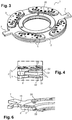
- the Figures 1 and 2 represent a pendular damping device 1 according to a first embodiment of the invention.
- the support 2 comprises a noise attenuation system 30 occurring during an impact of each pendulous body 3 against the support 2.
- This system 30 is disposed here only one side of the support, then comprising a single plastic layer 31 axially clamped between the support 2 and a single clamping piece 32.
- the plastic layer 31 is for example made of elastomer.
- the plastic is for example elastomer.
- the clamping piece 32 is for example a sheet, which can be made of steel.
- the clamping piece 32 has an inner radius substantially equal to the inner radius of the plastic layer 31 and still substantially equal to the inner radius of the support 2.
- the axial clamping of the plastic layer 31 is in the example considered obtained during the fixing of the clamping piece 32 on the support 2 via rivets 33 while the plastic layer 31 has been previously positioned between the support 2 and the clamping piece 32.
- Three rivets 33 distributed uniformly about the axis X are provided here.
- the plastic layer 31 is overmolded on the rivets 33 and the rivets are then riveted on the support 2 and on the clamping piece 32.
- This plastic layer 31 is here positioned radially inwardly relative to the pendulum body 3, forming a stop for the displacement radially inwardly of the pendulum mass 5 arranged on the same side 4 of the support as this plastic layer 31.
- the noise attenuation device 30 extends here on the one hand on the first side of the support 2 and on the other hand on the second side of the support 2.
- each plastic layer 31 can be performed via a single set of rivets 33, the latter being firstly riveted on the first clamping piece 32 and secondly on the second clamping piece 32 .
- each plastic layer 31 can here be positioned radially inwardly relative to the pendulum body 3, forming a stop for the displacement radially inwardly of the pendulum mass. 5 disposed on the same side 4 of the support as this plastic layer 31.
- the pendular bodies 3 are arranged radially inwardly relative to the elastic return members and the connection of the support to the rest of the secondary flywheel is effected via connecting means such as screws or rivets.
- FIG. 5 and 6 which applies both to a pendular damping device according to the first example of implementation that according to the second example of implementation, differs from what has been described in that the clamping piece 32 allows the connection of the support 2 to the rest of the secondary flywheel.
- the clamping piece 32 is for example the end portion of a connecting plate of the pendulum damping device to the rest of the secondary flywheel.
- the pendulum damping device 1 of the Figures 5 and 6 could present pendulum bodies radially at the elastic return members of the double damping flywheel, or arranged radially outwardly relative to these elastic return members.
- the invention is not limited to what has just been described.
- the device 1 is devoid of abutment damping members interposed between each connecting member 6 and the radially inner edge of the corresponding window 19 to come simultaneously in contact with this body 6 and the support 2 in certain relative positions of the support 2 and a pendulum body 3, such as the positions of abutment at the end of a displacement from the rest position to filter a torsional oscillation, such abutment damping members could be provided.
Landscapes
- Engineering & Computer Science (AREA)
- General Engineering & Computer Science (AREA)
- Physics & Mathematics (AREA)
- Acoustics & Sound (AREA)
- Aviation & Aerospace Engineering (AREA)
- Mechanical Engineering (AREA)
- Vibration Prevention Devices (AREA)
Applications Claiming Priority (1)
| Application Number | Priority Date | Filing Date | Title |
|---|---|---|---|
| FR1652374A FR3049032B1 (fr) | 2016-03-21 | 2016-03-21 | Dispositif d'amortissement pendulaire |
Publications (1)
| Publication Number | Publication Date |
|---|---|
| EP3222877A1 true EP3222877A1 (de) | 2017-09-27 |
Family
ID=56990486
Family Applications (1)
| Application Number | Title | Priority Date | Filing Date |
|---|---|---|---|
| EP17161248.4A Withdrawn EP3222877A1 (de) | 2016-03-21 | 2017-03-16 | Pendel-dämpfungsvorrichtung |
Country Status (4)
| Country | Link |
|---|---|
| EP (1) | EP3222877A1 (de) |
| KR (1) | KR102375202B1 (de) |
| CN (1) | CN107218347A (de) |
| FR (1) | FR3049032B1 (de) |
Cited By (1)
| Publication number | Priority date | Publication date | Assignee | Title |
|---|---|---|---|---|
| CN113366243A (zh) * | 2019-01-28 | 2021-09-07 | 舍弗勒技术股份两合公司 | 具有端部止挡件的离心力摆装置 |
Families Citing this family (1)
| Publication number | Priority date | Publication date | Assignee | Title |
|---|---|---|---|---|
| KR102617093B1 (ko) * | 2018-12-24 | 2023-12-26 | 주식회사 카펙발레오 | 내장형 진자를 이용한 진자 댐퍼 및 이를 포함하는 차량용 토크 컨버터 |
Citations (9)
| Publication number | Priority date | Publication date | Assignee | Title |
|---|---|---|---|---|
| DE102009042836A1 (de) * | 2008-11-24 | 2010-05-27 | Luk Lamellen Und Kupplungsbau Beteiligungs Kg | Fliehkraftpendel |
| DE102010034812A1 (de) * | 2009-09-17 | 2011-03-24 | Schaeffler Technologies Gmbh & Co. Kg | Schwungrad und Reibungskupplung |
| DE102011086532A1 (de) | 2010-12-15 | 2012-06-21 | Schaeffler Technologies Gmbh & Co. Kg | Fliehkraftpendel und Kupplungsscheibe mit demselben |
| WO2012150399A1 (fr) * | 2011-05-04 | 2012-11-08 | Valeo Embrayages | Dispositif d'amortissement de torsion a masselottes pendulaires a basculement limite |
| DE102012214996A1 (de) * | 2011-09-23 | 2013-03-28 | Schaeffler Technologies AG & Co. KG | Fliehkraftpendel mit Axialschwingungsdämpfung |
| DE102013204711A1 (de) * | 2013-03-18 | 2014-09-18 | Zf Friedrichshafen Ag | Tilgerschwingungsdämpfer |
| DE102014214712A1 (de) * | 2013-08-07 | 2015-02-12 | Schaeffler Technologies Gmbh & Co. Kg | Drehschwingungsdämpfer |
| DE102014207961A1 (de) * | 2014-04-28 | 2015-10-29 | Zf Friedrichshafen Ag | Tilgerschwingungsdämpfer und Verfahren zum Bereitstellen eines Tilgerschwingungsdämpfers |
| FR3025274A1 (fr) * | 2014-08-28 | 2016-03-04 | Valeo Embrayages | Dispositif d'amortissement d'oscillations de torsion |
Family Cites Families (2)
| Publication number | Priority date | Publication date | Assignee | Title |
|---|---|---|---|---|
| DE102012207862A1 (de) * | 2012-05-11 | 2013-11-14 | Zf Friedrichshafen Ag | Drehschwingungsdämpfungsanordnung, insbesondere für den Antriebsstrang eines Fahrzeugs |
| FR3009853B1 (fr) * | 2013-08-23 | 2015-08-14 | Valeo Embrayages | Procede de montage d'un dispositif d'amortissement pendulaire |
-
2016
- 2016-03-21 FR FR1652374A patent/FR3049032B1/fr not_active Expired - Fee Related
-
2017
- 2017-03-16 EP EP17161248.4A patent/EP3222877A1/de not_active Withdrawn
- 2017-03-20 KR KR1020170034557A patent/KR102375202B1/ko active Active
- 2017-03-21 CN CN201710169115.7A patent/CN107218347A/zh active Pending
Patent Citations (9)
| Publication number | Priority date | Publication date | Assignee | Title |
|---|---|---|---|---|
| DE102009042836A1 (de) * | 2008-11-24 | 2010-05-27 | Luk Lamellen Und Kupplungsbau Beteiligungs Kg | Fliehkraftpendel |
| DE102010034812A1 (de) * | 2009-09-17 | 2011-03-24 | Schaeffler Technologies Gmbh & Co. Kg | Schwungrad und Reibungskupplung |
| DE102011086532A1 (de) | 2010-12-15 | 2012-06-21 | Schaeffler Technologies Gmbh & Co. Kg | Fliehkraftpendel und Kupplungsscheibe mit demselben |
| WO2012150399A1 (fr) * | 2011-05-04 | 2012-11-08 | Valeo Embrayages | Dispositif d'amortissement de torsion a masselottes pendulaires a basculement limite |
| DE102012214996A1 (de) * | 2011-09-23 | 2013-03-28 | Schaeffler Technologies AG & Co. KG | Fliehkraftpendel mit Axialschwingungsdämpfung |
| DE102013204711A1 (de) * | 2013-03-18 | 2014-09-18 | Zf Friedrichshafen Ag | Tilgerschwingungsdämpfer |
| DE102014214712A1 (de) * | 2013-08-07 | 2015-02-12 | Schaeffler Technologies Gmbh & Co. Kg | Drehschwingungsdämpfer |
| DE102014207961A1 (de) * | 2014-04-28 | 2015-10-29 | Zf Friedrichshafen Ag | Tilgerschwingungsdämpfer und Verfahren zum Bereitstellen eines Tilgerschwingungsdämpfers |
| FR3025274A1 (fr) * | 2014-08-28 | 2016-03-04 | Valeo Embrayages | Dispositif d'amortissement d'oscillations de torsion |
Cited By (1)
| Publication number | Priority date | Publication date | Assignee | Title |
|---|---|---|---|---|
| CN113366243A (zh) * | 2019-01-28 | 2021-09-07 | 舍弗勒技术股份两合公司 | 具有端部止挡件的离心力摆装置 |
Also Published As
| Publication number | Publication date |
|---|---|
| KR102375202B1 (ko) | 2022-03-16 |
| FR3049032A1 (fr) | 2017-09-22 |
| KR20170109497A (ko) | 2017-09-29 |
| FR3049032B1 (fr) | 2018-08-17 |
| CN107218347A (zh) | 2017-09-29 |
Similar Documents
| Publication | Publication Date | Title |
|---|---|---|
| EP3380750B1 (de) | Pendeldämpfungsvorrichtung | |
| EP3190310B1 (de) | Pendel-dämpfungsvorrichtung | |
| EP3332147B1 (de) | Vorrichtung zur dämpfung von torsionsschwingungen | |
| EP3153741B1 (de) | Vorrichtung zur torsionsschwingungsdämpfung | |
| EP3026295B1 (de) | Vorrichtung zur torsionsschwingungsdämpfung | |
| FR3070737B1 (fr) | Dispositif damortissement pendulaire | |
| EP3225877A1 (de) | Halterung für pendel-dämpfungsvorrichtung, und pendel-dämpfungsvorrichtung, die so eine halterung umfasst | |
| EP3128204B1 (de) | Vorrichtung zur torsionsschwingungsdämpfung | |
| EP3249258B1 (de) | Pendel-dämpfungsvorrichtung | |
| FR3049033A1 (fr) | Dispositif d'amortissement pendulaire | |
| EP3222876B1 (de) | Tilgerschwingungsdämpfer | |
| FR3050500A1 (fr) | Dispositif d'amortissement pendulaire | |
| EP3222877A1 (de) | Pendel-dämpfungsvorrichtung | |
| FR3047530A1 (fr) | Dispositif d'amortissement pendulaire | |
| FR3051523A1 (fr) | Dispositif d'amortissement d'oscillations de torsion pour systeme de transmission de vehicule | |
| FR3025275A1 (fr) | Dispositif d'amortissement d'oscillations de torsion | |
| FR3050499A1 (fr) | Dispositif d'amortissement pendulaire | |
| FR3049031A1 (fr) | Dispositif d'amortissement pendulaire | |
| FR3048271A1 (fr) | Dispositif d'amortissement pendulaire | |
| FR3033859A1 (fr) | Dispositif d'amortissement d'oscillations de torsion pour systeme de transmission de vehicule | |
| FR3047784A1 (fr) | Dispositif d'amortissement pendulaire | |
| EP3073147B1 (de) | Vorrichtung zur torsionsschwingungsdämpfung für das antriebssystem eines fahrzeugs | |
| FR3047785A1 (fr) | Dispositif d'amortissement pendulaire | |
| FR3029254A1 (fr) | Dispositif d'amortissement d'oscillations de torsion | |
| FR3029253A1 (fr) | Dispositif d'amortissement d'oscillations de torsion |
Legal Events
| Date | Code | Title | Description |
|---|---|---|---|
| PUAI | Public reference made under article 153(3) epc to a published international application that has entered the european phase |
Free format text: ORIGINAL CODE: 0009012 |
|
| 17P | Request for examination filed |
Effective date: 20170316 |
|
| AK | Designated contracting states |
Kind code of ref document: A1 Designated state(s): AL AT BE BG CH CY CZ DE DK EE ES FI FR GB GR HR HU IE IS IT LI LT LU LV MC MK MT NL NO PL PT RO RS SE SI SK SM TR |
|
| AX | Request for extension of the european patent |
Extension state: BA ME |
|
| RIN1 | Information on inventor provided before grant (corrected) |
Inventor name: MAHE, HERVE Inventor name: VERHOOG, ROEL Inventor name: ROUZE, GUILLAUME Inventor name: SALVADORI, DAVID |
|
| INTG | Intention to grant announced |
Effective date: 20190614 |
|
| STAA | Information on the status of an ep patent application or granted ep patent |
Free format text: STATUS: THE APPLICATION IS DEEMED TO BE WITHDRAWN |
|
| 18D | Application deemed to be withdrawn |
Effective date: 20191025 |