EP3223193B1 - Dispositif de traitement d'images, procédé de traitement d'images et programme de traitement d'images - Google Patents
Dispositif de traitement d'images, procédé de traitement d'images et programme de traitement d'images Download PDFInfo
- Publication number
- EP3223193B1 EP3223193B1 EP17160530.6A EP17160530A EP3223193B1 EP 3223193 B1 EP3223193 B1 EP 3223193B1 EP 17160530 A EP17160530 A EP 17160530A EP 3223193 B1 EP3223193 B1 EP 3223193B1
- Authority
- EP
- European Patent Office
- Prior art keywords
- finger
- point
- base
- standard
- straight line
- Prior art date
- Legal status (The legal status is an assumption and is not a legal conclusion. Google has not performed a legal analysis and makes no representation as to the accuracy of the status listed.)
- Not-in-force
Links
Images





Classifications
-
- G—PHYSICS
- G06—COMPUTING OR CALCULATING; COUNTING
- G06V—IMAGE OR VIDEO RECOGNITION OR UNDERSTANDING
- G06V40/00—Recognition of biometric, human-related or animal-related patterns in image or video data
- G06V40/10—Human or animal bodies, e.g. vehicle occupants or pedestrians; Body parts, e.g. hands
- G06V40/12—Fingerprints or palmprints
- G06V40/1347—Preprocessing; Feature extraction
-
- G—PHYSICS
- G06—COMPUTING OR CALCULATING; COUNTING
- G06V—IMAGE OR VIDEO RECOGNITION OR UNDERSTANDING
- G06V10/00—Arrangements for image or video recognition or understanding
- G06V10/20—Image preprocessing
- G06V10/32—Normalisation of the pattern dimensions
-
- G—PHYSICS
- G06—COMPUTING OR CALCULATING; COUNTING
- G06V—IMAGE OR VIDEO RECOGNITION OR UNDERSTANDING
- G06V40/00—Recognition of biometric, human-related or animal-related patterns in image or video data
- G06V40/10—Human or animal bodies, e.g. vehicle occupants or pedestrians; Body parts, e.g. hands
- G06V40/107—Static hand or arm
- G06V40/11—Hand-related biometrics; Hand pose recognition
-
- G—PHYSICS
- G06—COMPUTING OR CALCULATING; COUNTING
- G06V—IMAGE OR VIDEO RECOGNITION OR UNDERSTANDING
- G06V40/00—Recognition of biometric, human-related or animal-related patterns in image or video data
- G06V40/50—Maintenance of biometric data or enrolment thereof
-
- G—PHYSICS
- G06—COMPUTING OR CALCULATING; COUNTING
- G06V—IMAGE OR VIDEO RECOGNITION OR UNDERSTANDING
- G06V40/00—Recognition of biometric, human-related or animal-related patterns in image or video data
- G06V40/10—Human or animal bodies, e.g. vehicle occupants or pedestrians; Body parts, e.g. hands
- G06V40/12—Fingerprints or palmprints
- G06V40/13—Sensors therefor
- G06V40/1312—Sensors therefor direct reading, e.g. contactless acquisition
Definitions
- a certain aspect of embodiments described herein relates to an image processing device, an image processing method and an image processing program.
- a position of input biometric information may be different from that of enrollment biometric information because of inputting condition or environment of a user.
- the difference of the positions may cause an authentication error.
- a guide for guiding a hand posture may be used in order to reduce influence of the position difference.
- an image of a hand without a part thereof may be captured.
- a possibility of the authentication error may be increased. It is difficult to provide a guide to a mobile electronic device. And so, there is disclosed a technology of a palm authentication for reducing influence of the position difference (for example, see Japanese Patent Application Publication No. 2010-26658 ; Japanese Patent Application Publication No.
- the present invention has been made in view of those circumstances, and an object thereof is to provide an image processing device, an image processing method and an image processing program that are capable of correcting position gap with high accuracy.
- an image processing device according to claim 1.
- an image processing device according to claim 3.
- FIG. 1A illustrates a hardware structure of a biometric authentication device 100 in accordance with a first embodiment.
- FIG. 1B illustrates a schematic view of a biometric sensor 105 described later.
- the biometric authentication device 100 has a CPU (Central Processing Unit) 101, a RAM (Random Access Memory) 102, a memory device 103, a display device 104, the biometric sensor 105, a communication device 106, and an attribute information acquirer 107. These components are connected by a bus or the like.
- CPU Central Processing Unit
- RAM Random Access Memory
- the CPU 101 is a central processing unit.
- the CPU 101 includes one or more core.
- the RAM 102 is a volatile memory temporally storing a program executed by the CPU 101, a data processed by the CPU 101, and so on.
- the memory device 103 is a nonvolatile memory device.
- the memory device 103 may be a SSD (Solid State Drive) such as a ROM (Read Only Memory) or a flash memory, or a hard disk driven by a hard disk drive.
- the memory device 103 stores an image processing program in accordance with the first embodiment.
- the display device 104 is such as a liquid crystal display, an electroluminescence panel, or the like and displays a result of each process described later.
- the biometric sensor 105 is a sensor for acquiring biometric information of a user and acquires a palm image of a user without touching in the first embodiment.
- the biometric sensor 105 is such as a CMOS (Complementary Metal Oxide Semiconductor) camera.
- the biometric sensor 105 acquires an outline of a palm, a palm print, a palm shape based on information of visible light.
- the biometric sensor 105 may acquire a blood vessel pattern such as a vein pattern with use of near-infrared light. It is preferable that the palm image includes a whole of a palm including finger tips. However, the palm image may include a part of the palm to a middle of a finger.
- the communication device 106 is a connection interface with LAN (Local Area Network) or the like.
- the attribute information acquirer 107 is such as a keyboard, a mouse or the like and is a device to input ID, a user name, a password or the like for identifying a user.
- a biometric authentication program stored in the memory device 103 is developed to the RAM 102.
- the CPU 101 executes the biometric authentication program developed to the RAM 102.
- each process is executed by the biometric authentication device 100.
- an enrollment process, an authentication process and so on are executed.
- a biometric feature acquired from a palm image captured by the biometric sensor 105 is associated with a user and is stored in a database.
- a palm print, a vessel pattern, a palm shape or the like is extracted from a palm image is enrolled in the database as the biometric feature.
- a biometric feature acquired by the biometric sensor 105 is collated with an enrollment feature enrolled in the database.
- a similarity between a vein pattern acquired in the authentication process and a vein pattern enrolled in the database is equal to or more than a threshold, it is determined that a user of the biometric feature for collation is the same as an enrolled user. Details of the enrollment process and the authentication process will be descried later.
- FIG. 2 illustrates a block diagram of functions achieved by execution of the biometric authentication program.
- a normalized image generator 10 By the execution of the biometric authentication program, a normalized image generator 10, a biometric feature extractor 20, an enroller 30, a collator 40, a database 50 and so on are achieved.
- the normalized image generator 10 has a function as an image processing device. Therefore, a program for achieving the normalized image generator acts as an image processing program.
- the normalized image generator 10 acts as a base point detector 11, a first standard point calculator 12, a second standard point calculator 13, and a convertor 14.
- a stand alone terminal is illustrated in the example of FIG. 1A, FIG. 1B and FIG.2 .
- the structure is not limited to the stand alone terminal.
- the embodiment can be applied to a client server system. In the embodiment, a description will be given of the stand alone terminal for simplification.
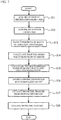
- FIG. 3 illustrates a flowchart of details of the enrollment process. A description will be given of the enrollment process based on FIG. 2 and FIG. 3 .
- the attribute information acquirer 107 acquires attribute information of a user (Step S1).
- the biometric sensor 105 captures a palm image of the user who holds his hand against the biometric sensor 105 (Step S2).
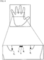
- the base point detector 11 detects positions of base points of two adjacent fingers from the palm image captured in Step S2 (Step S3). For example, as illustrated in FIG. 4 , the base point detector 11 detects base points M 1 and M 2 of a middle finger and base points R 1 and R 2 of a ring finger.
- the base point M 1 of the middle finger is a base point on the side of the ring finger.
- the base point M 2 of the middle finger is a base point on the side of an index finger.
- the base point R 1 of the ring finger is a base point on the side of the middle finger.
- the base point R 2 of the ring finger is a base point on the side of the little finger. It is possible to detect these base points by an edge detection method such as a Laplacian filter, a corner detection method such as a SUSAN (Smallest Univalue Segment Assimilating Nucleus).
- the first standard point calculator 12 calculates a first standard point A of the palm based on the positions of the base points detected in Step S3 (Step S4). For example, the first standard point calculator 12 calculates a top edge point of the palm that is the farthest from a wrist, as the first standard point A, as illustrated in FIG. 4 . For example, the first standard point calculator 12 calculates a midpoint between the base point M 1 and the base point R 1 as the first standard point A. Alternately, the first standard point calculator 12 may calculate a cross point of a straight line M 1 M 2 and a straight line R 1 R 2 as a top edge point A. The first standard point calculator 12 may calculate a point between the base point M 1 and the base point R 1 as the first standard point.
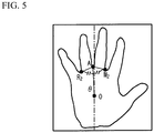
- the second standard point calculator 13 calculates a second standard point O based on the two of the base points detected in Step S3 and the first standard point A calculated in Step S4 (Step S5). For example, as illustrated in FIG. 5 , the second standard point calculator 13 calculates a point on a bisector of ⁇ M 2 AR 2 as the second standard point O, the point indicating a center position of the palm achieving a predetermined length ratio of a line segment AO and a line segment M 1 M 2 . In this case, the length ratio of the line segment AO and the line segment M 1 M 2 may be a simple integer number ratio such as 3:1. Alternately, a plurality of palm images captured in advance may be prepared.
- M 1 , M 2 , A and O may be artificially added to the images. And, statistics information such as an average or a median value of the length ratio of the line segment AO and the line segment M 1 M 2 may be used. Although the length ratio is the line segment AO : the line segment M 1 M 2 in the embodiment, intervals of two base points such as R 1 R 2 or M 2 R 2 may be used.
- the convertor 14 generates a normalized image by applying an affine conversion to the palm image captured in Step S2 (Step S6).
- the convertor 14 converts a palm image I(x, y) into an image I'(x', y') in accordance with the following formula (1) in order to move the first standard point A to a center of a top edge of the image and move the second standard point O(x 0 , y 0 ) to the center of the image.
- a size of the palm image in a horizontal direction is "w”
- a size in a vertical direction is "h”.
- a length of a line segment OA is "d”.
- An inclination of the line segment OA with respect to the vertical direction of the image is " ⁇ ".
- x ' y ' 1 S x cos ⁇ ⁇ sin ⁇ T x sin ⁇ S y cos ⁇ T y 0 0 1 x y 1
- FIG. 6 illustrates a normalized image in which the first standard point A moves to a top edge center of the image and the second standard point O(x 0 , y 0 ) moves to the image center.
- the biometric feature extractor 20 extracts a biometric feature from the normalized image (Step S7).
- a vein pattern is acquired as the biometric feature.
- the vein pattern includes a coordinate or a direction of an edge point or a branch point of a vein, or connection information of two branch points.
- the enroller 30 associates the attribute information acquired in Step S1 with the biometric feature extracted in Step S7 and enrolls the attribute information and the biometric feature in the database 50 (Step S8).
- the biometric feature enrolled in Step S8 is named an enrollment biometric feature. With the processes, the enrollment process is terminated.
- FIG. 7 illustrates a flowchart of details of the authentication process.
- Step S11 to Step S17 are the same as Step S1 to Step S7 of FIG. 3 .
- the biometric feature acquired in Step S17 is referred to as a biometric feature for collation.
- the collator 40 reads the enrollment biometric feature associated with the same attribute information from the database 50 and collates the enrollment biometric feature and the biometric feature for collation (Step S18). In concrete, the collator 40 determines whether a similarity between the enrollment biometric feature and the biometric feature for collation is equal to or more than a threshold and outputs the result.
- two adjacent fingers are a first finger and a second finger.
- a first standard point is a point between a base point of the first finger on the side of the second finger and a base point of the second finer on the side of the first finger.
- a second standard point is on a bisector of an angle between a straight line passing through a base point of the first finger on the opposite side of the second finger and the first standard point and a straight line passing through a base point of the second finger on the opposite side of the first finger and the first standard point.
- the first standard point and the second standard point are uniquely positioned in a hand of each user.
- a palm image is normalized by an affine conversion with use of these standard points as a standard, it is possible to stably make the same normalized images or normalized images similar to each other of the same user. Even if a part of a palm (for example, a lower part) is not included in the palm image, it is possible to make a normalized image. Accordingly, it is possible to correct a position gap with use of position information of a part of the palm image. Moreover, usability can be achieved by reducing the number of cases where a user retries holding of his hand. And a stable authentication can be achieved.
- the base points of the middle finger and the ring finger are used.
- other base points of other two adjacent fingers such as a pair of an index finger and a middle finger or a pair of a thumb and an index finger may be used.
- the base point detector 11 acts as a detector configured to detect a base point of a first finger and a base point of a second finger next to the first finger from the palm image.
- the first standard point calculator 12 acts as a first calculator configured to calculate a first standard point between a base point of the first finger on the second finger side and a base point of the second finger on the first finger side.
- the second standard point calculator 13 acts as a second calculator configured to calculate a second standard point on a bisector of an angle that is formed by a straight line passing through a base point of the first finger on an opposite side of the second finger and the first standard point and a straight line passing through a base point of the second finger on an opposite side of the first finger, and the first standard point.
- the convertor 14 acts as a convertor configured to apply an affine conversion to the palm image so that coordinates of the first standard point and the second standard point are converted into predetermined coordinates.
- a description will be given of a case where a normalized image is generated with use of base points of an index finger, base points of a middle finger, base points of a ring finger and base points of a little finger of a palm image.
- the following process executed by the base point detector 11, the first standard point calculator 12, the second standard point calculator 13 and the convertor 14 is a process executed in Step S1 to Step S6 of FIG. 3 and Step S11 to Step S16 of FIG. 7 .
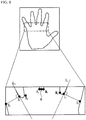
- the base point detector 11 detects the base points M 1 and M 2 of the middle finger, the base points R 1 and R 2 of the ring finger, the base points I 1 of the index finger on the middle finger side and the base point S 1 of the little finger on the ring finger side of the palm image captured by the biometric sensor 105, as illustrated in FIG. 8 .
- the base point detector 11 calculates an index finger vector indicating an edge direction of the middle finger side of the index finger and a little finger vector indicating an edge direction of the ring finger side of the little finger.
- the base point detector 11 calculates a straight line that has a direction of the index finger vector and passes through the base point I 1 as a straight line L 1 and a straight line that has a direction of the little finger vector and passes through the base point S 1 as the straight line L s .
- the base point detector 11 calculates a cross point between a line that passes through the base point I 1 and is vertical to the straight line L 1 and an edge of outside of the index finger as the base point I 2 and a cross point between a line that passes through the base point S 1 and is vertical to the straight line L s and an edge of outside of the little finger as the base point S 2 . It is possible to detect a direction of the index finger vector or the little finger vector by using an edge detection method such as a Laplacian filter.
- the first standard point calculator 12 calculates the first standard point A.
- the first standard point calculator 12 calculates an upper edge point of the palm that is the furthest from the wrist, as the first standard point A, as illustrated in FIG. 8 .
- the first standard point calculator 12 calculates a midpoint between the base point M 1 and the base point R 1 , as the first standard point A.
- the first standard point calculator 12 may calculate a cross point of the straight line M 1 M 2 and the straight line R 1 R 2 , as the first standard point A.
- the first standard point calculator 12 may calculate a cross point of the straight line M 1 I 1 and the straight line R 1 S 1 , as the first standard point A.
- the first standard point calculator 12 may calculate a point between the base point M 1 and the base point R 1 , as the first standard point.
- the second standard point calculator 13 calculates the second standard point W from two base points of a finger and the first standard point A. For example, as illustrated in FIG. 9 , the second standard point calculator 13 calculates the second standard point W that is on a bisector of ⁇ I 2 AS 2 and is a lower edge point of a palm that achieves a predetermined length ratio of a line segment AW and a line segment I 2 S 2 . A ratio for calculating the second standard point W may be determined with the processes that are the same as the first embodiment.
- the convertor 14 makes a normalized biometric image by applying an affine conversion to the palm image.
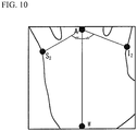
- the convertor 14 converts an image I (x, y) into an image I' (x', y') in accordance with the following formula (2) in order to move the first standard point A to a center of a top edge of the image and move the second standard point W (x 0 , y 0 ) into a center of a lower edge of the image.
- a horizontal size of the palm image is "w”.
- a vertical size of the palm image is "h”.
- a length of the line segment OW is "d”.
- An inclination of the line segment AW with respect to the vertical direction of the image is " ⁇ ".
- x ' y ' 1 S x cos ⁇ ⁇ sin ⁇ T x sin ⁇ S y cos ⁇ T y 0 0 1 x y 1
- FIG. 10 illustrates a normalized image in which the first standard point A moves to a top edge center of the image and the second standard point W(x 0 , y 0 ) moves to the lower edge center of the image.
- the first standard point is a point between the base point of the middle finger on the side of the ring finger and the base point of the ring finger on the side of the middle finger.
- the second standard point is on a bisector of an angle formed by a straight line passing through the base point of the index finger on the side of the thumb and the first standard point, the base point of the little finger on the opposite side of the ring finger, and the first standard point.
- the first standard point and the second standard point are uniquely positioned in a hand of each user. Therefore, when a palm image is normalized by an affine conversion with use of these standard points as a standard, it is possible to stably make the same normalized images or normalized images similar to each other of the same user.
- the base point detector 11 acts as a detector configured to detect a base point of a middle finger, a base point of a ring finger, a base point of an index finger on a thumb side, and a base point of a little finger on an opposite side of the ring finger.
- the first standard point calculator 12 acts as a first calculator configured to calculate a first standard point between a base point of the middle finger on the ring finger side and a base point of the ring finger on the middle finger side.
- the second standard point calculator 13 acts as a second calculator configured to calculate a second standard point on a bisector of an angle that is formed by a straight line passing through a base point of the index finger on the thumb side and the first standard point and a straight line passing through a base point of the little finger on an opposite side of the ring finger, and the first standard point.
- the convertor 14 acts as a convertor configured to apply an affine conversion to the palm image so that coordinates of the first standard point and the second standard point are converted into predetermined coordinates.
- a description will be given of a case where a normalized image is generated with use of base points of the index finger, base points of the middle finger, base points of the ring finger and base points of the little finger of a palm image.
- the base point detector 11 detects the base points M 1 and M 2 of the middle finger, the base points R 1 and R 2 of the ring finger, the base points I 1 and I 2 of the index finger and the base points S1 and S2 of the little finger with the same method as the second embodiment, as illustrated in FIG. 8 .
- the first standard point calculator 12 calculates the first standard point A with the same method as the second embodiment, as illustrated in FIG. 8 .
- the second standard point calculator 13 calculates the standard point O from two base points of a finger and the first standard point A with the same processes as the first embodiment. For example, as illustrated in FIG. 11 , the second standard point calculator 13 calculates a point on a bisector of ⁇ M 2 AR 2 as the standard point O, the point indicating a center position of the palm achieving a predetermined length ratio of a line segment AO and a line segment M 1 M 2 . And the second standard point calculator 13 calculates a point on a bisector of ⁇ I 2 AS 2 , the point indicating a lower edge position of the palm achieving a predetermined length ratio of a line segment AW and a line segment I 2 S 2 .
- the ratio for calculating the first standard point A, the standard point O and the standard point W may be determined with the same method as the first embodiment.
- the convertor 14 generates a normalized biometric image by applying an affine conversion to a palm image. For example, the convertor 14 moves the first standard point A to the center of the top edge of the image, moves the standard point O to the center of the image, and moves the standard point W to the center of the lower edge of the image.
- the convertor 14 divides the palm image into four regions with a straight line t that is a bisector of ZAOW, a half line OA extending toward the first standard point A, and a half line OW extending toward the second standard point W.
- the regions are a region I to a region IV.
- the convertor 14 applies an affine conversion to the regions and combines the affine-converted regions.
- a horizontal size of the palm image is "w”.
- a vertical size of the palm image is "h”.
- a position of the standard point O is (x 0 , y 0 ).
- a length of the line segment OA is “d”.
- An inclination of the line segment OA with respect to the vertical direction of the image is " ⁇ A ".
- An inclination of the straight line t with respect to the horizontal direction is " ⁇ t ".
- An inclination of the line segment OW with respect to the vertical direction of the image is " ⁇ w ".
- An image I 1 of the region I before conversion is (x, y).
- An image I 1 ' of the region I after conversion is (x', y').
- the convertor 14 performs calculation in accordance with the following formula (3), and converts the direction of the line segment OA into the vertical direction with respect to the image and converts the direction of the straight line t into the horizontal direction with respect to the image.
- x ' y ' 1 S x cos ⁇ ⁇ sin ⁇ T x S x cos ⁇ tan ⁇ + sin ⁇ ⁇ sin ⁇ tan ⁇ + S y cos ⁇ T x tan ⁇ + T y 0 0 1 x y 1
- the following relations are satisfied.
- the convertor 14 applies an affine conversion to the regions II to IV.
- a length dW of the lie segment OW and an inclination ⁇ w of the line segment OW with respect to the vertical direction of the image are used instead of the length dA of the line segment OA and the inclination ⁇ A of the line segment OA with respect to the vertical direction of the image.
- the first standard point A, the standard point O and the standard point W are uniquely positioned in a hand of each user. Therefore, when the palm image is normalized by an affine-conversion with used of the standard points as standard, it is possible to stably make the same normalized images or normalized images similar to each other of the same user. Even if a part of a palm (for example, a lower part) is not included in the palm image, it is possible to make a normalized image. Accordingly, it is possible to correct a position gap with use of position information of a part of the palm image. Moreover, usability can be achieved by reducing the number of cases where a user retries holding of his hand. And a stable authentication can be achieved.
- the palm image is divided into the four regions by the bisector of ⁇ AOW, the half straight line OA and the half straight line OW.
- the palm image is divided into a region of which position gap is large and a region of which position gap is small, even if a closing degree of the index finger is larger than those of other fingers and a degree of the position gap differs according to a position of the palm image. Therefore, it is possible to generate a stable normalized biometric image because the position gap of each region can be corrected.
- the base point detector 11 acts as a detector configured to detect a base point of a middle finger, a base point of a ring finger, a base point of an index finger on a thumb side, and a base point of a little finger on an opposite side of the ring finger.
- the first standard point calculator 12 acts as a first calculator configured to calculate a first standard point between a base point of the middle finger on the ring finger side and a base point of the ring finger on the middle finger side.
- the second standard point calculator 13 acts as a second calculator configured to calculate a second standard point on a bisector of an angle that is formed by a straight line passing through a base point of the index finger on the thumb side and the first standard point and a straight line passing through a base point of the little finger on an opposite side of the ring finger, and the first standard point.
- the first standard point A for calculating the standard point O corresponds to a first reference point.
- the standard point O corresponds to a second reference point.
- the convertor 14 acts as a convertor configured to apply an affine conversion to the palm image so that coordinates of the first standard point and the second standard point are converted into predetermined coordinates.
Landscapes
- Engineering & Computer Science (AREA)
- Physics & Mathematics (AREA)
- General Physics & Mathematics (AREA)
- Multimedia (AREA)
- Theoretical Computer Science (AREA)
- Human Computer Interaction (AREA)
- Computer Vision & Pattern Recognition (AREA)
- Collating Specific Patterns (AREA)
- Measurement Of The Respiration, Hearing Ability, Form, And Blood Characteristics Of Living Organisms (AREA)
- Image Processing (AREA)
- Image Analysis (AREA)
Claims (15)
- Dispositif de traitement d'image comprenant :un capteur biométrique (105) configuré pour capturer une image de la paume ;un détecteur (11) configuré pour détecter deux points de base des deux côtés d'un premier doigt et deux points de base des deux côtés d'un deuxième doigt adjacent au premier doigt à partir de l'image de la paume, le point de base du premier doigt du côté du deuxième doigt et le point de base du deuxième doigt du côté du premier doigt étant distincts ;un premier calculateur (12) configuré pour calculer un premier point standard entre un des points de base du premier doigt du côté du deuxième doigt et un des points de base du deuxième doigt du côté du premier doigt en utilisant une position du point de base du premier doigt du côté du deuxième doigt et une position du point de base du deuxième doigt du côté du premier doigt ;un deuxième calculateur (13) configuré pour calculer un deuxième point standard sur une bissectrice d'un angle qui est formé par une droite passant par un des points de base du premier doigt d'un côté opposé du deuxième doigt et le premier point standard et une droite passant par un des points de base du deuxième doigt d'un côté opposé du premier doigt, et le premier point standard ; etun convertisseur (14) configuré pour appliquer une transformation affine à l'image de la paume de sorte que les coordonnées du premier point standard et du deuxième point standard soient transformées en des coordonnées prédéterminées.
- Dispositif de traitement d'image selon la revendication 1, dans lequel le premier calculateur calcule un point médian entre le point de base du premier doigt du côté du deuxième doigt et le point de base du deuxième doigt du côté du premier doigt ou un point d'intersection d'une droite passant par les deux points de base du premier doigt et d'une droite passant par les deux points de base du deuxième doigt, comme premier point standard.
- Dispositif de traitement d'image comprenant :un capteur biométrique (105) configuré pour capturer une image de la paume ;un détecteur (11) configuré pour détecter deux points de base des deux côtés d'un majeur, deux points de base des deux côtés d'un annulaire, un point de base d'un index du côté d'un pouce, et un point de base d'un auriculaire d'un côté opposé de l'annulaire, le point de base de l'annulaire du côté du majeur et le point de base du majeur du côté de l'annulaire étant distincts ;un premier calculateur (12) configuré pour calculer un premier point standard entre un des points de base du majeur du côté de l'annulaire et un des points de base de l'annulaire du côté du majeur en utilisant une position du point de base du majeur du côté de l'annulaire et une position du point de base de l'annulaire du côté du majeur ;un deuxième calculateur (13) configuré pour calculer un deuxième point standard sur une bissectrice d'un angle qui est formé par une droite passant par un des points de base de l'index du côté du pouce et le premier point standard et une droite passant par le point de base de l'auriculaire d'un côté opposé de l'annulaire, et le premier point standard ; etun convertisseur (14) configuré pour appliquer une transformation affine à l'image de la paume de sorte que les coordonnées du premier point standard et du deuxième point standard soient transformées en des coordonnées prédéterminées.
- Dispositif de traitement d'image selon la revendication 3, dans lequel le premier calculateur calcule un point médian entre un point de base du majeur du côté de l'annulaire et un point de base de l'annulaire du côté du majeur, un point d'intersection d'une droite passant par les deux points de base du majeur et d'une droite passant par les deux points de base de l'annulaire, ou un point d'intersection d'une droite passant par un point de base de l'index du côté du majeur et un point de base du majeur du côté de l'annulaire et d'une droite passant par un point de base de l'auriculaire du côté de l'annulaire et un point de base de l'annulaire du côté du majeur, comme premier point standard.
- Dispositif de traitement d'image selon la revendication 3 ou 4, dans lequel :le détecteur est configuré pour détecter des points de base d'un premier doigt et des points de base d'un deuxième doigt adjacent au premier doigt à partir de l'image de la paume ;le deuxième calculateur est configuré pour calculer un deuxième point de référence sur une bissectrice d'un angle qui est formé par une droite passant par un premier point de référence entre un point de base du premier doigt du côté du deuxième doigt et un point de base du deuxième doigt du côté du premier doigt et un point de base du premier doigt d'un côté opposé du deuxième doigt et une droite passant par un point de base du deuxième doigt d'un côté opposé du premier doigt, et le premier point de référence ; etle convertisseur est configuré pour appliquer une transformation affine à l'image de la paume de sorte que les coordonnées du premier point standard, du deuxième point standard et du deuxième point de référence soient transformées en des coordonnées prédéterminées.
- Procédé de traitement d'image comprenant :la capture d'une image de la paume par un capteur biométrique ;la détection de deux points de base des deux côtés d'un premier doigt et de deux points de base des deux côtés d'un deuxième doigt adjacent au premier doigt à partir de l'image de la paume, le point de base du premier doigt du côté du deuxième doigt et le point de base du deuxième doigt du côté du premier doigt étant distincts ;le calcul d'un premier point standard entre un des points de base du premier doigt du côté du deuxième doigt et un des points de base du deuxième doigt du côté du premier doigt en utilisant une position du point de base du premier doigt du côté du deuxième doigt et une position du point de base du deuxième doigt du côté du premier doigt ;le calcul d'un deuxième point standard sur une bissectrice d'un angle qui est formé par une droite passant par un des points de base du premier doigt d'un côté opposé du deuxième doigt et le premier point standard et une droite passant par un des points de base du deuxième doigt d'un côté opposé du premier doigt, et le premier point standard ; etl'application d'une transformation affine à l'image de la paume de sorte que les coordonnées du premier point standard et du deuxième point standard soient transformées en des coordonnées prédéterminées.
- Procédé de traitement d'image selon la revendication 6, dans lequel dans le calcul du premier point standard, un point médian entre le point de base du premier doigt du côté du deuxième doigt et le point de base du deuxième doigt du côté du premier doigt ou un point d'intersection d'une droite passant par les deux points de base du premier doigt et d'une droite passant par les deux points de base du deuxième doigt est calculé comme premier point standard.
- Procédé de traitement d'image comprenant :la capture d'une image de la paume par un capteur biométrique ;la détection de deux points de base des deux côtés d'un majeur, de deux points de base des deux côtés d'un annulaire, d'un point de base d'un index du côté d'un pouce, et d'un point de base d'un auriculaire d'un côté opposé de l'annulaire, le point de base de l'annulaire du côté du majeur et le point de base du majeur du côté de l'annulaire étant distincts ;le calcul d'un premier point standard entre un des points de base du majeur du côté de l'annulaire et un des points de base de l'annulaire du côté du majeur en utilisant une position du point de base du majeur du côté de l'annulaire et une position du point de base de l'annulaire du côté du majeur ;le calcul d'un deuxième point standard sur une bissectrice d'un angle qui est formé par une droite passant par un des points de base de l'index du côté du pouce et le premier point standard et une droite passant par le point de base de l'auriculaire d'un côté opposé de l'annulaire, et le premier point standard ; etl'application d'une transformation affine à l'image de la paume de sorte que les coordonnées du premier point standard et du deuxième point standard soient transformées en des coordonnées prédéterminées.
- Procédé de traitement d'image selon la revendication 8, dans lequel dans le calcul du premier point standard, un point médian entre un point de base du majeur du côté de l'annulaire et un point de base de l'annulaire du côté du majeur, un point d'intersection d'une droite passant par les deux points de base du majeur et d'une droite passant par les deux points de base de l'annulaire, ou un point d'intersection d'une droite passant par un point de base de l'index du côté du majeur et un point de base du majeur du côté de l'annulaire et d'une droite passant par un point de base de l'auriculaire du côté de l'annulaire et un point de base de l'annulaire du côté du majeur est calculé comme premier point standard.
- Procédé de traitement d'image selon les revendications 8 ou 9, dans lequel
dans la détection, des points de base d'un premier doigt et des points de base d'un deuxième doigt adjacent au premier doigt sont détectés à partir de l'image de la paume ;
dans le calcul du deuxième point standard, un deuxième point de référence est calculé sur une bissectrice d'un angle qui est formé par une droite passant par un premier point de référence entre un point de base du premier doigt du côté du deuxième doigt et un point de base du deuxième doigt du côté du premier doigt et un point de base du premier doigt d'un côté opposé du deuxième doigt et une droite passant par un point de base du deuxième doigt d'un côté opposé du premier doigt, et le premier point de référence ; et
dans l'application de la transformation affine, la transformation affine est appliquée à l'image de la paume de sorte que les coordonnées du premier point standard, du deuxième point standard et du deuxième point de référence soient transformées en des coordonnées prédéterminées. - Programme de traitement d'image amenant un ordinateur à exécuter un processus, le processus comprenant :la capture d'une image de la paume par un capteur biométrique ;la détection de deux points de base des deux côtés d'un premier doigt et de deux points de base des deux côtés d'un deuxième doigt adjacent au premier doigt à partir de l'image de la paume, le point de base du premier doigt du côté du deuxième doigt et le point de base du deuxième doigt du côté du premier doigt étant distincts ;le calcul d'un premier point standard entre un des points de base du premier doigt du côté du deuxième doigt et un des points de base du deuxième doigt du côté du premier doigt en utilisant une position du point de base du premier doigt du côté du deuxième doigt et une position du point de base du deuxième doigt du côté du premier doigt ;le calcul d'un deuxième point standard sur une bissectrice d'un angle qui est formé par une droite passant par un des points de base du premier doigt d'un côté opposé du deuxième doigt et le premier point standard et une droite passant par un des points de base du deuxième doigt d'un côté opposé du premier doigt, et le premier point standard ; etl'application d'une transformation affine à l'image de la paume de sorte que les coordonnées du premier point standard et du deuxième point standard soient transformées en des coordonnées prédéterminées.
- Programme de traitement d'image selon la revendication 11, dans lequel dans le calcul du premier point standard, un point médian entre le point de base du premier doigt du côté du deuxième doigt et le point de base du deuxième doigt du côté du premier doigt ou un point d'intersection d'une droite passant par les deux points de base du premier doigt et d'une droite passant par les deux points de base du deuxième doigt est calculé comme premier point standard.
- Programme de traitement d'image comprenant :la capture d'une image de la paume par un capteur biométrique ;la détection de deux points de base des deux côtés d'un majeur, de deux points de base des deux côtés d'un annulaire, d'un point de base d'un index du côté d'un pouce, et d'un point de base d'un auriculaire d'un côté opposé de l'annulaire, le point de base de l'annulaire du côté du majeur et le point de base du majeur du côté de l'annulaire étant distincts ;le calcul d'un premier point standard entre un des points de base du majeur du côté de l'annulaire et un des points de base de l'annulaire du côté du majeur en utilisant une position du point de base du majeur du côté de l'annulaire et une position du point de base de l'annulaire du côté du majeur ;le calcul d'un deuxième point standard sur une bissectrice d'un angle qui est formé par une droite passant par un des points de base de l'index du côté du pouce et le premier point standard et une droite passant par le point de base de l'auriculaire d'un côté opposé de l'annulaire, et le premier point standard ; etl'application d'une transformation affine à l'image de la paume de sorte que les coordonnées du premier point standard et du deuxième point standard soient transformées en des coordonnées prédéterminées.
- Programme de traitement d'image selon la revendication 13, dans lequel dans le calcul du premier point standard, un point médian entre un point de base du majeur du côté de l'annulaire et un point de base de l'annulaire du côté du majeur, un point d'intersection d'une droite passant par les deux points de base du majeur et d'une droite passant par les deux points de base de l'annulaire, ou un point d'intersection d'une droite passant par un point de base de l'index du côté du majeur et un point de base du majeur du côté de l'annulaire et d'une droite passant par un point de base de l'auriculaire du côté de l'annulaire et un point de base de l'annulaire du côté du majeur est calculé comme premier point standard.
- Programme de traitement d'image selon les revendications 13 ou 14, dans lequel
dans la détection, des points de base d'un premier doigt et des points de base d'un deuxième doigt adjacent au premier doigt sont détectés à partir de l'image de la paume ;
dans le calcul du deuxième point standard, un deuxième point de référence est calculé sur une bissectrice d'un angle qui est formé par une droite passant par un premier point de référence entre un point de base du premier doigt du côté du deuxième doigt et un point de base du deuxième doigt du côté du premier doigt et un point de base du premier doigt d'un côté opposé du deuxième doigt et une droite passant par un point de base du deuxième doigt d'un côté opposé du premier doigt, et le premier point de référence ; et
dans l'application de la transformation affine, la transformation affine est appliquée à l'image de la paume de sorte que les coordonnées du premier point standard, du deuxième point standard et du deuxième point de référence soient transformées en des coordonnées prédéterminées.
Applications Claiming Priority (1)
| Application Number | Priority Date | Filing Date | Title |
|---|---|---|---|
| JP2016060784A JP6658188B2 (ja) | 2016-03-24 | 2016-03-24 | 画像処理装置、画像処理方法および画像処理プログラム |
Publications (2)
| Publication Number | Publication Date |
|---|---|
| EP3223193A1 EP3223193A1 (fr) | 2017-09-27 |
| EP3223193B1 true EP3223193B1 (fr) | 2018-12-26 |
Family
ID=58461053
Family Applications (1)
| Application Number | Title | Priority Date | Filing Date |
|---|---|---|---|
| EP17160530.6A Not-in-force EP3223193B1 (fr) | 2016-03-24 | 2017-03-13 | Dispositif de traitement d'images, procédé de traitement d'images et programme de traitement d'images |
Country Status (3)
| Country | Link |
|---|---|
| US (1) | US10438078B2 (fr) |
| EP (1) | EP3223193B1 (fr) |
| JP (1) | JP6658188B2 (fr) |
Families Citing this family (8)
| Publication number | Priority date | Publication date | Assignee | Title |
|---|---|---|---|---|
| CN110349096B (zh) * | 2019-06-14 | 2024-08-02 | 平安科技(深圳)有限公司 | 手掌图像的校正方法、装置、设备及存储介质 |
| CN111160290B (zh) * | 2019-12-31 | 2023-09-01 | 广州微盾科技股份有限公司 | 一种提取手掌静脉有效区域的方法 |
| JP7731362B2 (ja) * | 2020-02-26 | 2025-08-29 | マジック リープ, インコーポレイテッド | ウェアラブルシステムのための手のジェスチャ入力 |
| JP7518748B2 (ja) * | 2020-12-11 | 2024-07-18 | Kddi株式会社 | 画像処理装置、画像処理方法及びコンピュータプログラム |
| CN117173734B (zh) * | 2022-05-27 | 2025-02-18 | 腾讯科技(深圳)有限公司 | 手掌轮廓提取、控制指令生成方法、装置和计算机设备 |
| KR20240017702A (ko) * | 2022-08-01 | 2024-02-08 | 삼성전자주식회사 | 센서를 통해 사용자 제스처를 인식하는 디스플레이 장치 및 그 제어 방법 |
| JP7759007B2 (ja) * | 2022-09-01 | 2025-10-23 | 富士通株式会社 | 検出装置、検出方法、および検出プログラム |
| CN116959038A (zh) * | 2023-06-16 | 2023-10-27 | 腾讯科技(深圳)有限公司 | 掌纹识别方法、相关装置和介质 |
Family Cites Families (9)
| Publication number | Priority date | Publication date | Assignee | Title |
|---|---|---|---|---|
| JP3726714B2 (ja) * | 2001-06-18 | 2005-12-14 | 日本電気株式会社 | 掌紋照合システム、プログラム、および、掌紋照合方法 |
| MX2009004749A (es) * | 2006-11-03 | 2009-09-28 | Snowflake Technologies Corp | Metodo y aparato para extraccion y correspondencia de detalle biometrico. |
| JP5393072B2 (ja) | 2008-07-16 | 2014-01-22 | Kddi株式会社 | 掌位置検出装置、掌紋認証装置、携帯電話端末、プログラム、および掌位置検出方法 |
| JP5747642B2 (ja) | 2011-05-06 | 2015-07-15 | 富士通株式会社 | 生体認証装置、生体認証システム、生体認証サーバ、生体認証クライアント及び生体認証装置制御方法 |
| JP6024141B2 (ja) * | 2012-03-23 | 2016-11-09 | 富士通株式会社 | 生体情報処理装置、生体情報処理方法、および生体情報処理プログラム |
| JP6532642B2 (ja) | 2013-07-30 | 2019-06-19 | 富士通株式会社 | 生体情報認証装置および生体情報処理方法 |
| WO2015015843A1 (fr) | 2013-08-02 | 2015-02-05 | 三菱電機株式会社 | Dispositif et procédé de détermination de geste, dispositif fonctionnant sur la base de geste, programme, et support d'informations |
| KR101526426B1 (ko) * | 2013-12-31 | 2015-06-05 | 현대자동차 주식회사 | 제스처 인식 장치 및 방법 |
| KR102429865B1 (ko) * | 2015-06-17 | 2022-08-05 | 한국전자통신연구원 | 사용자 인증 장치 |
-
2016
- 2016-03-24 JP JP2016060784A patent/JP6658188B2/ja not_active Expired - Fee Related
-
2017
- 2017-03-13 US US15/457,256 patent/US10438078B2/en active Active
- 2017-03-13 EP EP17160530.6A patent/EP3223193B1/fr not_active Not-in-force
Non-Patent Citations (1)
| Title |
|---|
| M.L. ANITHA ET AL: "Extraction of Region of Interest (ROI) for Palm Print and Inner Knuckle Print", INTERNATIONAL JOURNAL OF COMPUTER APPLICATIONS, vol. 124, no. 14, 1 August 2015 (2015-08-01), pages 21 - 26, XP055495358, DOI: 10.5120/ijca2015905784 * |
Also Published As
| Publication number | Publication date |
|---|---|
| JP6658188B2 (ja) | 2020-03-04 |
| JP2017174228A (ja) | 2017-09-28 |
| US20170277963A1 (en) | 2017-09-28 |
| EP3223193A1 (fr) | 2017-09-27 |
| US10438078B2 (en) | 2019-10-08 |
Similar Documents
| Publication | Publication Date | Title |
|---|---|---|
| EP3223193B1 (fr) | Dispositif de traitement d'images, procédé de traitement d'images et programme de traitement d'images | |
| JP6557943B2 (ja) | 画像照合装置、画像センサ、処理システム、画像照合方法 | |
| EP2833294B1 (fr) | Dispositif permettant d'extraire un vecteur de caractéristiques biométriques, procédé pour extraire un vecteur de caractéristiques biométriques et programme pour extraire un vecteur de caractéristiques biométriques | |
| US10733274B2 (en) | Biometric authentication using gesture | |
| JP5930023B2 (ja) | 生体認証装置、生体認証方法及び生体認証用コンピュータプログラム | |
| US10460207B2 (en) | Image processing device, image processing method and computer-readable non-transitory medium | |
| US9418274B2 (en) | Biometric authentication technique utilizing image data of both hands | |
| EP3070631B1 (fr) | Appareil terminal, procédé d'authentification biométrique et programme d'authentification biométrique | |
| CN108230383A (zh) | 手部三维数据确定方法、装置及电子设备 | |
| EP3249576A1 (fr) | Dispositif de traitement d'informations biométriques, procédé de traitement d'informations biométriques et programme de traitement d'informations biométriques | |
| EP3214575B1 (fr) | Dispositif, procédé et programme de traitement d'image biologique | |
| WO2021001322A1 (fr) | Segmentation par division forcée d'images d'empreintes digitales sans contact | |
| US10528805B2 (en) | Biometric authentication apparatus, biometric authentication method, and computer-readable storage medium | |
| US20210383098A1 (en) | Feature point extraction device, feature point extraction method, and program storage medium | |
| JP2015094968A (ja) | 生体情報抽出装置、生体情報抽出方法、および生体情報抽出プログラム | |
| WO2015141007A1 (fr) | Système d'enregistrement/authentification biométrique et procédé d'enregistrement/authentification biométrique | |
| JP2014081877A (ja) | 情報処理装置、サイン情報取得方法、および、プログラム | |
| US20240404317A1 (en) | Image processing apparatus, image processing method, and non-transitory computer-readable storage medium | |
| KR20190028970A (ko) | 손동작 인식을 이용한 보안 시스템 | |
| Msiza et al. | A novel fingerprint re-alignment solution that uses the tfcp as a reference | |
| WO2019021177A1 (fr) | Procédé et système d'appariement des images d'empreintes digitales | |
| Ryu et al. | Individual authentication through hand posture recognition using Multi-Hilbert Scanning Distance | |
| WO2019021173A1 (fr) | Système et procédé de réglage de l'orientation d'une image capturée d'une empreinte digitale oblique |
Legal Events
| Date | Code | Title | Description |
|---|---|---|---|
| PUAI | Public reference made under article 153(3) epc to a published international application that has entered the european phase |
Free format text: ORIGINAL CODE: 0009012 |
|
| STAA | Information on the status of an ep patent application or granted ep patent |
Free format text: STATUS: THE APPLICATION HAS BEEN PUBLISHED |
|
| AK | Designated contracting states |
Kind code of ref document: A1 Designated state(s): AL AT BE BG CH CY CZ DE DK EE ES FI FR GB GR HR HU IE IS IT LI LT LU LV MC MK MT NL NO PL PT RO RS SE SI SK SM TR |
|
| AX | Request for extension of the european patent |
Extension state: BA ME |
|
| STAA | Information on the status of an ep patent application or granted ep patent |
Free format text: STATUS: REQUEST FOR EXAMINATION WAS MADE |
|
| 17P | Request for examination filed |
Effective date: 20180222 |
|
| RBV | Designated contracting states (corrected) |
Designated state(s): AL AT BE BG CH CY CZ DE DK EE ES FI FR GB GR HR HU IE IS IT LI LT LU LV MC MK MT NL NO PL PT RO RS SE SI SK SM TR |
|
| GRAP | Despatch of communication of intention to grant a patent |
Free format text: ORIGINAL CODE: EPIDOSNIGR1 |
|
| STAA | Information on the status of an ep patent application or granted ep patent |
Free format text: STATUS: GRANT OF PATENT IS INTENDED |
|
| RIC1 | Information provided on ipc code assigned before grant |
Ipc: G06K 9/00 20060101AFI20180725BHEP Ipc: G06K 9/42 20060101ALI20180725BHEP |
|
| INTG | Intention to grant announced |
Effective date: 20180815 |
|
| RIN1 | Information on inventor provided before grant (corrected) |
Inventor name: MATSUNAMI, TOMOAKI |
|
| GRAS | Grant fee paid |
Free format text: ORIGINAL CODE: EPIDOSNIGR3 |
|
| GRAA | (expected) grant |
Free format text: ORIGINAL CODE: 0009210 |
|
| STAA | Information on the status of an ep patent application or granted ep patent |
Free format text: STATUS: THE PATENT HAS BEEN GRANTED |
|
| AK | Designated contracting states |
Kind code of ref document: B1 Designated state(s): AL AT BE BG CH CY CZ DE DK EE ES FI FR GB GR HR HU IE IS IT LI LT LU LV MC MK MT NL NO PL PT RO RS SE SI SK SM TR |
|
| REG | Reference to a national code |
Ref country code: GB Ref legal event code: FG4D |
|
| REG | Reference to a national code |
Ref country code: CH Ref legal event code: EP |
|
| REG | Reference to a national code |
Ref country code: AT Ref legal event code: REF Ref document number: 1082436 Country of ref document: AT Kind code of ref document: T Effective date: 20190115 |
|
| REG | Reference to a national code |
Ref country code: IE Ref legal event code: FG4D |
|
| REG | Reference to a national code |
Ref country code: DE Ref legal event code: R096 Ref document number: 602017001511 Country of ref document: DE |
|
| PG25 | Lapsed in a contracting state [announced via postgrant information from national office to epo] |
Ref country code: FI Free format text: LAPSE BECAUSE OF FAILURE TO SUBMIT A TRANSLATION OF THE DESCRIPTION OR TO PAY THE FEE WITHIN THE PRESCRIBED TIME-LIMIT Effective date: 20181226 Ref country code: LV Free format text: LAPSE BECAUSE OF FAILURE TO SUBMIT A TRANSLATION OF THE DESCRIPTION OR TO PAY THE FEE WITHIN THE PRESCRIBED TIME-LIMIT Effective date: 20181226 Ref country code: HR Free format text: LAPSE BECAUSE OF FAILURE TO SUBMIT A TRANSLATION OF THE DESCRIPTION OR TO PAY THE FEE WITHIN THE PRESCRIBED TIME-LIMIT Effective date: 20181226 Ref country code: LT Free format text: LAPSE BECAUSE OF FAILURE TO SUBMIT A TRANSLATION OF THE DESCRIPTION OR TO PAY THE FEE WITHIN THE PRESCRIBED TIME-LIMIT Effective date: 20181226 Ref country code: NO Free format text: LAPSE BECAUSE OF FAILURE TO SUBMIT A TRANSLATION OF THE DESCRIPTION OR TO PAY THE FEE WITHIN THE PRESCRIBED TIME-LIMIT Effective date: 20190326 Ref country code: BG Free format text: LAPSE BECAUSE OF FAILURE TO SUBMIT A TRANSLATION OF THE DESCRIPTION OR TO PAY THE FEE WITHIN THE PRESCRIBED TIME-LIMIT Effective date: 20190326 |
|
| REG | Reference to a national code |
Ref country code: NL Ref legal event code: MP Effective date: 20181226 |
|
| REG | Reference to a national code |
Ref country code: LT Ref legal event code: MG4D |
|
| PG25 | Lapsed in a contracting state [announced via postgrant information from national office to epo] |
Ref country code: GR Free format text: LAPSE BECAUSE OF FAILURE TO SUBMIT A TRANSLATION OF THE DESCRIPTION OR TO PAY THE FEE WITHIN THE PRESCRIBED TIME-LIMIT Effective date: 20190327 Ref country code: RS Free format text: LAPSE BECAUSE OF FAILURE TO SUBMIT A TRANSLATION OF THE DESCRIPTION OR TO PAY THE FEE WITHIN THE PRESCRIBED TIME-LIMIT Effective date: 20181226 Ref country code: SE Free format text: LAPSE BECAUSE OF FAILURE TO SUBMIT A TRANSLATION OF THE DESCRIPTION OR TO PAY THE FEE WITHIN THE PRESCRIBED TIME-LIMIT Effective date: 20181226 Ref country code: AL Free format text: LAPSE BECAUSE OF FAILURE TO SUBMIT A TRANSLATION OF THE DESCRIPTION OR TO PAY THE FEE WITHIN THE PRESCRIBED TIME-LIMIT Effective date: 20181226 |
|
| REG | Reference to a national code |
Ref country code: AT Ref legal event code: MK05 Ref document number: 1082436 Country of ref document: AT Kind code of ref document: T Effective date: 20181226 |
|
| PG25 | Lapsed in a contracting state [announced via postgrant information from national office to epo] |
Ref country code: NL Free format text: LAPSE BECAUSE OF FAILURE TO SUBMIT A TRANSLATION OF THE DESCRIPTION OR TO PAY THE FEE WITHIN THE PRESCRIBED TIME-LIMIT Effective date: 20181226 |
|
| PG25 | Lapsed in a contracting state [announced via postgrant information from national office to epo] |
Ref country code: PT Free format text: LAPSE BECAUSE OF FAILURE TO SUBMIT A TRANSLATION OF THE DESCRIPTION OR TO PAY THE FEE WITHIN THE PRESCRIBED TIME-LIMIT Effective date: 20190426 Ref country code: IT Free format text: LAPSE BECAUSE OF FAILURE TO SUBMIT A TRANSLATION OF THE DESCRIPTION OR TO PAY THE FEE WITHIN THE PRESCRIBED TIME-LIMIT Effective date: 20181226 Ref country code: ES Free format text: LAPSE BECAUSE OF FAILURE TO SUBMIT A TRANSLATION OF THE DESCRIPTION OR TO PAY THE FEE WITHIN THE PRESCRIBED TIME-LIMIT Effective date: 20181226 Ref country code: CZ Free format text: LAPSE BECAUSE OF FAILURE TO SUBMIT A TRANSLATION OF THE DESCRIPTION OR TO PAY THE FEE WITHIN THE PRESCRIBED TIME-LIMIT Effective date: 20181226 Ref country code: PL Free format text: LAPSE BECAUSE OF FAILURE TO SUBMIT A TRANSLATION OF THE DESCRIPTION OR TO PAY THE FEE WITHIN THE PRESCRIBED TIME-LIMIT Effective date: 20181226 |
|
| PG25 | Lapsed in a contracting state [announced via postgrant information from national office to epo] |
Ref country code: SM Free format text: LAPSE BECAUSE OF FAILURE TO SUBMIT A TRANSLATION OF THE DESCRIPTION OR TO PAY THE FEE WITHIN THE PRESCRIBED TIME-LIMIT Effective date: 20181226 Ref country code: EE Free format text: LAPSE BECAUSE OF FAILURE TO SUBMIT A TRANSLATION OF THE DESCRIPTION OR TO PAY THE FEE WITHIN THE PRESCRIBED TIME-LIMIT Effective date: 20181226 Ref country code: SK Free format text: LAPSE BECAUSE OF FAILURE TO SUBMIT A TRANSLATION OF THE DESCRIPTION OR TO PAY THE FEE WITHIN THE PRESCRIBED TIME-LIMIT Effective date: 20181226 Ref country code: RO Free format text: LAPSE BECAUSE OF FAILURE TO SUBMIT A TRANSLATION OF THE DESCRIPTION OR TO PAY THE FEE WITHIN THE PRESCRIBED TIME-LIMIT Effective date: 20181226 Ref country code: IS Free format text: LAPSE BECAUSE OF FAILURE TO SUBMIT A TRANSLATION OF THE DESCRIPTION OR TO PAY THE FEE WITHIN THE PRESCRIBED TIME-LIMIT Effective date: 20190426 |
|
| REG | Reference to a national code |
Ref country code: DE Ref legal event code: R097 Ref document number: 602017001511 Country of ref document: DE |
|
| PG25 | Lapsed in a contracting state [announced via postgrant information from national office to epo] |
Ref country code: MC Free format text: LAPSE BECAUSE OF FAILURE TO SUBMIT A TRANSLATION OF THE DESCRIPTION OR TO PAY THE FEE WITHIN THE PRESCRIBED TIME-LIMIT Effective date: 20181226 Ref country code: DK Free format text: LAPSE BECAUSE OF FAILURE TO SUBMIT A TRANSLATION OF THE DESCRIPTION OR TO PAY THE FEE WITHIN THE PRESCRIBED TIME-LIMIT Effective date: 20181226 Ref country code: AT Free format text: LAPSE BECAUSE OF FAILURE TO SUBMIT A TRANSLATION OF THE DESCRIPTION OR TO PAY THE FEE WITHIN THE PRESCRIBED TIME-LIMIT Effective date: 20181226 |
|
| PLBE | No opposition filed within time limit |
Free format text: ORIGINAL CODE: 0009261 |
|
| STAA | Information on the status of an ep patent application or granted ep patent |
Free format text: STATUS: NO OPPOSITION FILED WITHIN TIME LIMIT |
|
| PG25 | Lapsed in a contracting state [announced via postgrant information from national office to epo] |
Ref country code: LU Free format text: LAPSE BECAUSE OF NON-PAYMENT OF DUE FEES Effective date: 20190313 |
|
| 26N | No opposition filed |
Effective date: 20190927 |
|
| REG | Reference to a national code |
Ref country code: BE Ref legal event code: MM Effective date: 20190331 |
|
| PG25 | Lapsed in a contracting state [announced via postgrant information from national office to epo] |
Ref country code: IE Free format text: LAPSE BECAUSE OF NON-PAYMENT OF DUE FEES Effective date: 20190313 |
|
| PG25 | Lapsed in a contracting state [announced via postgrant information from national office to epo] |
Ref country code: SI Free format text: LAPSE BECAUSE OF FAILURE TO SUBMIT A TRANSLATION OF THE DESCRIPTION OR TO PAY THE FEE WITHIN THE PRESCRIBED TIME-LIMIT Effective date: 20181226 Ref country code: BE Free format text: LAPSE BECAUSE OF NON-PAYMENT OF DUE FEES Effective date: 20190331 |
|
| PG25 | Lapsed in a contracting state [announced via postgrant information from national office to epo] |
Ref country code: TR Free format text: LAPSE BECAUSE OF FAILURE TO SUBMIT A TRANSLATION OF THE DESCRIPTION OR TO PAY THE FEE WITHIN THE PRESCRIBED TIME-LIMIT Effective date: 20181226 |
|
| PG25 | Lapsed in a contracting state [announced via postgrant information from national office to epo] |
Ref country code: MT Free format text: LAPSE BECAUSE OF NON-PAYMENT OF DUE FEES Effective date: 20190313 |
|
| REG | Reference to a national code |
Ref country code: CH Ref legal event code: PL |
|
| PG25 | Lapsed in a contracting state [announced via postgrant information from national office to epo] |
Ref country code: LI Free format text: LAPSE BECAUSE OF NON-PAYMENT OF DUE FEES Effective date: 20200331 Ref country code: CH Free format text: LAPSE BECAUSE OF NON-PAYMENT OF DUE FEES Effective date: 20200331 |
|
| PG25 | Lapsed in a contracting state [announced via postgrant information from national office to epo] |
Ref country code: CY Free format text: LAPSE BECAUSE OF FAILURE TO SUBMIT A TRANSLATION OF THE DESCRIPTION OR TO PAY THE FEE WITHIN THE PRESCRIBED TIME-LIMIT Effective date: 20181226 |
|
| PG25 | Lapsed in a contracting state [announced via postgrant information from national office to epo] |
Ref country code: HU Free format text: LAPSE BECAUSE OF FAILURE TO SUBMIT A TRANSLATION OF THE DESCRIPTION OR TO PAY THE FEE WITHIN THE PRESCRIBED TIME-LIMIT; INVALID AB INITIO Effective date: 20170313 |
|
| REG | Reference to a national code |
Ref country code: DE Ref legal event code: R079 Ref document number: 602017001511 Country of ref document: DE Free format text: PREVIOUS MAIN CLASS: G06K0009000000 Ipc: G06V0010000000 |
|
| PG25 | Lapsed in a contracting state [announced via postgrant information from national office to epo] |
Ref country code: MK Free format text: LAPSE BECAUSE OF FAILURE TO SUBMIT A TRANSLATION OF THE DESCRIPTION OR TO PAY THE FEE WITHIN THE PRESCRIBED TIME-LIMIT Effective date: 20181226 |
|
| PGFP | Annual fee paid to national office [announced via postgrant information from national office to epo] |
Ref country code: FR Payment date: 20230208 Year of fee payment: 7 |
|
| PGFP | Annual fee paid to national office [announced via postgrant information from national office to epo] |
Ref country code: GB Payment date: 20230202 Year of fee payment: 7 Ref country code: DE Payment date: 20230131 Year of fee payment: 7 |
|
| REG | Reference to a national code |
Ref country code: DE Ref legal event code: R119 Ref document number: 602017001511 Country of ref document: DE |
|
| GBPC | Gb: european patent ceased through non-payment of renewal fee |
Effective date: 20240313 |
|
| PG25 | Lapsed in a contracting state [announced via postgrant information from national office to epo] |
Ref country code: DE Free format text: LAPSE BECAUSE OF NON-PAYMENT OF DUE FEES Effective date: 20241001 |
|
| PG25 | Lapsed in a contracting state [announced via postgrant information from national office to epo] |
Ref country code: GB Free format text: LAPSE BECAUSE OF NON-PAYMENT OF DUE FEES Effective date: 20240313 |
|
| PG25 | Lapsed in a contracting state [announced via postgrant information from national office to epo] |
Ref country code: FR Free format text: LAPSE BECAUSE OF NON-PAYMENT OF DUE FEES Effective date: 20240331 |
|
| PG25 | Lapsed in a contracting state [announced via postgrant information from national office to epo] |
Ref country code: GB Free format text: LAPSE BECAUSE OF NON-PAYMENT OF DUE FEES Effective date: 20240313 Ref country code: FR Free format text: LAPSE BECAUSE OF NON-PAYMENT OF DUE FEES Effective date: 20240331 Ref country code: DE Free format text: LAPSE BECAUSE OF NON-PAYMENT OF DUE FEES Effective date: 20241001 |