EP3223242B1 - Mécanisme d'édition de courbe - Google Patents
Mécanisme d'édition de courbe Download PDFInfo
- Publication number
- EP3223242B1 EP3223242B1 EP16305337.4A EP16305337A EP3223242B1 EP 3223242 B1 EP3223242 B1 EP 3223242B1 EP 16305337 A EP16305337 A EP 16305337A EP 3223242 B1 EP3223242 B1 EP 3223242B1
- Authority
- EP
- European Patent Office
- Prior art keywords
- path
- points
- point
- curve
- user
- Prior art date
- Legal status (The legal status is an assumption and is not a legal conclusion. Google has not performed a legal analysis and makes no representation as to the accuracy of the status listed.)
- Not-in-force
Links
Images




Classifications
-
- G—PHYSICS
- G06—COMPUTING OR CALCULATING; COUNTING
- G06T—IMAGE DATA PROCESSING OR GENERATION, IN GENERAL
- G06T11/00—Two-dimensional [2D] image generation
- G06T11/20—Drawing from basic elements
- G06T11/26—Drawing of charts or graphs
-
- G—PHYSICS
- G06—COMPUTING OR CALCULATING; COUNTING
- G06T—IMAGE DATA PROCESSING OR GENERATION, IN GENERAL
- G06T11/00—Two-dimensional [2D] image generation
- G06T11/20—Drawing from basic elements
- G06T11/23—Drawing from basic elements using straight lines or curves
-
- G—PHYSICS
- G06—COMPUTING OR CALCULATING; COUNTING
- G06F—ELECTRIC DIGITAL DATA PROCESSING
- G06F16/00—Information retrieval; Database structures therefor; File system structures therefor
- G06F16/20—Information retrieval; Database structures therefor; File system structures therefor of structured data, e.g. relational data
- G06F16/26—Visual data mining; Browsing structured data
-
- G—PHYSICS
- G06—COMPUTING OR CALCULATING; COUNTING
- G06F—ELECTRIC DIGITAL DATA PROCESSING
- G06F3/00—Input arrangements for transferring data to be processed into a form capable of being handled by the computer; Output arrangements for transferring data from processing unit to output unit, e.g. interface arrangements
- G06F3/01—Input arrangements or combined input and output arrangements for interaction between user and computer
- G06F3/011—Arrangements for interaction with the human body, e.g. for user immersion in virtual reality
-
- G—PHYSICS
- G06—COMPUTING OR CALCULATING; COUNTING
- G06T—IMAGE DATA PROCESSING OR GENERATION, IN GENERAL
- G06T11/00—Two-dimensional [2D] image generation
- G06T11/10—Texturing; Colouring; Generation of textures or colours
Definitions
- the present invention relates to the definition of curves, and their use to manipulate data.
- Figure 1 shows a histogram representing a dataset.
- the histogram comprises an x axis and two y axes 101 and 102. Arranged along the x axis are a series of bars 110, 111, 112, 113, 114, 115, 116, 117.
- Histograms such as that shown in figure 1 are a common way to represent the content of a dataset, in a variety in different contexts.
- the data may be a two dimensional image.
- the first ordinate axis 101 may represent a number of pixels, and the abscissa may reflect pixel intensity, so that each of the bars represents the number of pixels in the image in a particular intensity range.
- Another example may be the representation of a three dimensional volume, for example defined in terms of a collection of voxels, each having a characteristic density or opacity, such that the x axis may reflect voxel density or opacity, so that each of the bars represents the number of voxels in the volume in a particular density or opacity range.
- Volumetric datasets are found in many fields, such as engineering, material sciences, medical imaging, astrophysics. The exploration of volumetric datasets is not trivial, and is heavily impacted by the specific needs of users. In most airports for example, security agents deal with such data exploration in the context of baggage inspections.
- X-ray and tomography are two commonly used fluoroscopic scanning systems. X-ray systems provide a flattened 2D luggage scan while tomography systems produce transversal scans, also called slices. Thanks to data processing techniques such as the Radon transform, these systems can produce a full 3D scan, comprising a set of voxels with corresponding density data. Since the resulting X-ray scanned image only contains voxel or pixel densities, it cannot display the original material colours.
- the standard colour visual mapping uses three different colours (orange, green, and blue) to display the data density.
- Orange colour corresponds to low density (mainly organic items).
- blue colour is used for high density values (i.e. metal).
- green colour corresponds to the superposition of different kinds of materials or average density materials.
- the second Y axis 102 may represent a weighting to be applied to the bars at different positions on the x axis.
- a flat line 120 represents a 100% weighting to all bars equally.
- Figure 2 shows a histogram representing a weighted dataset.
- Figure 2 shows a histogram similar to that of figure 1 , however in this case the line 220 representing the weighting, filter or transfer function while 100% for bars to the left of the x axis, falls to zero for bars to the right of the x axis.
- bars 210, 211, 212, 213, 214, 215, 216, 217 are compared to the bars 110, 111, 112, 113, 114, 115, 116, 117 of figure 1 , where it will be noted that while bars 210, 211, 212 are identical to bars 110, 111, 112, bars 213, 214, 215, 216 and 217 are increasingly attenuated as they approach the right of the x axis, and the filter function 220 falls away to zero.
- the transfer curve may map the voxel density with a specific colour (including its transparency).
- the transfer function can be 1, 2 or n dimensional and can be of great help to isolate structures of interest in the data. Thanks to the colour blending process, suitable transfer function can also reveal iso surfaces, that is, surfaces that represent points of a constant value, or hide density to improve the data visualization.
- a corresponding filter can be applied to the original data, which when displayed in graphical form will exhibit a corresponding shift in appearance.
- the possibility of imposing subtle shifts in the representation in this way on the basis of the underlying properties of the data can be used to highlight or suppress certain parts of the dataset. This may in turn make it easier to interpret the dataset, to identify formations therein, and so on.
- the curve may be defined as a composite bezier curve, which the user can modify by adding or moving control points.
- Generation/modification of the curve is based on an algorithm configured to intuitively and dynamically move control points of the curve in response to the user input.
- the user input may include direct interaction with portions of the curve itself, as well as direct control of the end points and/or control points.
- the algorithm ensures that the generated/modified curve represents a valid mathematical function, while further ensuring that the generated or modified curve appears visually smooth.
- This mechanism provides a subtle and incremental mechanism for developing a path as required, with less tendency for overshoot and oscillation around the desired path. As such, the desired path can be achieved more rapidly, with a lower total demand on system resources, and a reduced likelihood of errors.
- Figure 3 shows a curve to which embodiments may be applied.
- a curve 300 defined by three straight sections 301, 302, 303. Sections 301 and 302 intersect at point 311, and sections 302 and 303 intersect at point 312. Section 301 terminates at anchor point 310, and section 303 terminates at anchor point 313, so that the curve 300 itself also terminates at anchor points 310 and 313.
- This curve may represent a transfer curve as described above.
- Figure 4 shows a set of curves in accordance with an embodiment.
- a curve 300 as described above, and a further curve 400 defined by two straight sections 401, 402. Sections 401 and 402 intersect at point 421. Section 401 terminates at point 420, and section 402 terminates at point 422, so that the curve 400 itself also terminates at anchor points 420 and 422.
- this second curve 400 may be the result of a user interaction.
- This second curve 400 is provided as a means for influencing the first curve 300.
- Figure 5 shows the steps of a method in accordance with an embodiment.
- figure 5 shows the steps of a method of defining a continuous path.
- the method starts at step 500 before proceeding to step 510, at which a first path comprising a plurality of points is defined.
- This first path may correspond for example to the curve 300 of figure 3 .
- the method then proceeds to steps 520 at which a second path comprising a plurality of points is defined.
- This second path may correspond for example to the curve 400 of figure 4 .
- the method proceeds to step 530 at which each point on said first path is moved towards respective points on the second path in a manner analogous to an attractive force, said movement being limited in a manner analogous to an elastic connection between the particles of said first path, where the positions of said second path are fixed, before terminating at step 540.
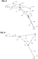
- Figure 6 illustrates step 530 of the method of figure 5 .
- Figure 6 shows a first path 300 and second path 400 as described above with reference to figures 3, 4 and 5 .
- the movement at step 530 of the point 311 will be considered.
- the three points on the second path 420, 421, 422 are each considered to exert an attraction the point 311, represented by the arrows 631, 632, 633.
- the adjacent points 310 and 312 on the first path 300 are considered to be attached to the point 311 by an elastic restraint, such that any deflection of the point 311 towards the second path in response to the attraction it exerts will be resisted by an opposing attraction, represented by the lines 630, 634.
- the terminal points 310, 313 are assumed to be fixed in position.
- Figure 7 further illustrates step 530 of the method of figure 5 .
- Figure 7 shows a first path 300 and second path 400 as described above with reference to figures 3, 4 and 5 .
- the movement at step 530 of the point 312 will be considered.
- the three points on the second path 420, 421, 422 are each considered to exert an attraction the point 312, represented by the arrows 741, 742, 743.
- the adjacent points 311 and 313 on the first path 300 are considered to be attached to the point 312 by an elastic restraint, such that any deflection of the point 312 towards the second path in response to the attraction it exerts will be resisted by an opposing attraction, represented by the lines 740, 744.
- the terminal points 310, 313 are assumed to be fixed in position.
- first path 300 as described above only has two mobile points, it will be appreciated that the same considerations may be applied to a path having any number of points. Furthermore, it will be appreciated that any movement of a point on the first path will modify the direction and magnitude of the attractions experienced by other points in the first path, so that it will be necessary to resolve all of the attractions simultaneously.
- Figure 8 shows the adjusted first curve combining the effects of figures 6 and 7 .
- an adjusted first curve 800 defined by points 210, 811, 812, 213, joined by lines 801, 802, 803.
- the point 211 has been moved under the influence of the attraction of points 320, 321, 322 to the position of 811
- the point 212 has been moved under the influence of the attraction of points 320, 321, 322 to the position of 812.
- Points 210 and 213 are fixed and as such have not moved.
- the attractive force between points of the first path and points of the second may be modelled as diminishing as a function of the distance between two points concerned.
- the attractive force between points of the first path and points of the second may be modelled as being inversely proportional to the square of the distance between two points concerned.
- the attractive force between points of the first path and points of the second may be modelled as being analogous to a magnetic or gravitational attraction.
- the resistive force between adjacent points of the first path may be modelled as being proportional to the increase in distance between the respective points.
- the first path as described above may be used as the transfer curve for application to a dataset as described above.
- the second path may be defined by a user input.
- This user input may be in the form of a gesture.
- This user input may be provided by means of a touch pad, mouse, digital pen or stylus, touch sensitive display, motion controller, eye tracker or any other suitable input system.
- the first path need not be displayed to the user.
- the second path need not be displayed to the user.
- the second path itself may no longer be required, and the new positions of the points 311, 312 may simply be defined.
- the path may continue to be defined in terms of a set of balanced forces, which will generally be susceptible to simplification, for example by defining the equivalent attraction to one or more predefined points required to achieve the same result.
- Figure 9 shows a simplified dynamic path definition.
- the first path may be used as a transfer curve defining a transfer function for use in filtering a colour / intensity histogram for example as described above, this approach affords a particularly refined mechanism for user interactions with the transfer function.
- the user may pull the first path back and forth, providing a mechanism for correcting excessive effects.
- the attraction may be negative (i.e. repulsive) in nature. It may be greater as a function of distance, rather than inversely related as described above. The relationship between attractive effect and distance may be dictated by any function as required.
- a plurality of types of second line each type having a characteristic type of attractive effect, chosen for example from the possibilities outlined above.
- the user may select from a palette of different drawing tools, each of which will affect the first path to a different degree, or in accordance with a different principle.
- the in accordance with the process of figure 5 there may be defined a plurality of types of second line, each associated with a different attractive effect, and the process may comprise the further steps of receiving a user input specifying one of the plurality of types of second line, and at said step of moving each point on first path with respects to points on second path, determining each movement as a function of the attractive effect associated with the selected line type.
- the curve has been presented as a series of straight lines approximating a smooth curve, it will be appreciated that the described approach extends to any convenient manner of defining a line.
- the curve may be defined by a composite Bezier where the points on the line may correspond to the vertices of the composite Bezier.
- the curve may correspond to a bitmap representation of the curve, where each point is a pixel, and the attractive force of each pixel is weighted according to the level of shading after interpolation.
- datasets such as two dimensional raster images or three dimensional voxel based representations are often processed for representation using a transfer function defined by a curve.
- a mechanism for manually adjusting such curves whereby a user adds a second curve.
- the transfer curve is recalculated so as to draw closer to the second curve.
- the attractive effect of the points of the first curve on those of adjacent points on the first curve and on those of the second may be attractive or repellent, may vary in any manner as a function of distance, and in particular may imitate the effects of physical forces such as magnetic, elastic, etc.
- the disclosed methods can take form of an entirely hardware embodiment (e.g.FPGA), an entirely software embodiment (for example to control a system according to the invention) or an embodiment containing both hardware and software elements.
- embodiments may comprise a number of subsystems, functional elements or means adapted to implement the invention in communication with each other, and/or with standard fixed function or programmable elements for example as described below.
- Software embodiments include but are not limited to applications, firmware, resident software, microcode, etc.
- the invention can take the form of a computer program product accessible from a computer-usable or computer-readable medium providing program code for use by or in connection with a computer or an instruction execution system.
- a computer-usable or computer-readable can be any apparatus that can contain, store, communicate, propagate, or transport the program for use by or in connection with the instruction execution system, apparatus, or device.
- the medium can be an electronic, magnetic, optical, electromagnetic, infrared, or semiconductor system (or apparatus or device) or a propagation medium.
- the methods and processes described herein may be implemented in whole or part by a user device. These methods and processes may be implemented by computer-application programs or services, an application-programming interface (API), a library, and/or other computer-program product, or any combination of such entities.
- API application-programming interface
- the user device may be a mobile device such as a smart phone or tablet, a drone, a computer or any other device with processing capability, such as a robot or other connected device.
- these datasets are associated with points on a sliding scale of one, two or three dimensions.
- a point corresponding to a particular dataset is selected by a user via a mouse pointer or the like , it is rendered as a graphical representation and presented to the user.
- an intermediate point is selected, an interpolation of the datasets corresponding to the nearby points is generated and the resulting dataset rendered as a graphical representation and presented to the user.
- the interaction may be implemented with a slider bar type widget having hybrid behaviour such that clicking on the bar causes the button to jump to the nearest point corresponding to a data, while sliding to a chosen intermediate position activates the interpolation of adjacent datasets.
- Figure 10 shows a generic computing system suitable for implementation of embodiments of the invention.
- a system includes a logic device 1001 and a storage device 1002.
- the system may optionally include a display subsystem 1011, input/output subsystem 1003, communication subsystem 1020, and/or other components not shown.
- Logic device 1001 includes one or more physical devices configured to execute instructions.
- the logic device 1001 may be configured to execute instructions that are part of one or more applications, services, programs, routines, libraries, objects, components, data structures, or other logical constructs.
- Such instructions may be implemented to perform a task, implement a data type, transform the state of one or more components, achieve a technical effect, or otherwise arrive at a desired result.
- the logic device 1001 may include one or more processors configured to execute software instructions. Additionally or alternatively, the logic device may include one or more hardware or firmware logic devices configured to execute hardware or firmware instructions. Processors of the logic device may be single-core or multi-core, and the instructions executed thereon may be configured for sequential, parallel, and/or distributed processing. Individual components of the logic device 1001 optionally may be distributed among two or more separate devices, which may be remotely located and/or configured for coordinated processing. Aspects of the logic device 1001 may be virtualized and executed by remotely accessible, networked computing devices configured in a cloud-computing configuration.
- Storage device 1002 includes one or more physical devices configured to hold instructions executable by the logic device to implement the methods and processes described herein. When such methods and processes are implemented, the state of storage 1002 device may be transformed-e.g., to hold different data.
- Storage device 1002 may include removable and/or built-in devices.
- Storage device 602 may comprise one or more types of storage device including optical memory (e.g., CD, DVD, HD-DVD, Blu-Ray Disc, etc.), semiconductor memory (e.g., FLASH, RAM, EPROM, EEPROM, etc.), and/or magnetic memory (e.g., hard-disk drive, floppy-disk drive, tape drive, MRAM, etc.), among others.
- Storage device may include volatile, nonvolatile, dynamic, static, read/write, read-only, random-access, sequential-access, location-addressable, file-addressable, and/or content-addressable devices.
- the system may comprise an interface 1003 adapted to support communications between the Logic device 1001 and further system components.
- additional system components may comprise removable and/or built-in extended storage devices.
- Extended storage devices may comprise one or more types of storage device including optical memory 1032 (e.g., CD, DVD, HD-DVD, Blu-Ray Disc, etc.), semiconductor memory 1033 (e.g., RAM, EPROM, EEPROM, FLASH etc.), and/or magnetic memory 1031 (e.g., hard-disk drive, floppy-disk drive, tape drive, MRAM, etc.), among others.
- Such extended storage device may include volatile, nonvolatile, dynamic, static, read/write, read-only, random-access, sequential-access, location-addressable, file-addressable, and/or content-addressable devices.
- storage device includes one or more physical devices, and excludes propagating signals per se.
- aspects of the instructions described herein alternatively may be propagated by a communication medium (e.g., an electromagnetic signal, an optical signal, etc.), as opposed to being stored on a storage device.
- a communication medium e.g., an electromagnetic signal, an optical signal, etc.
- logic device 1001 and storage device 1002 may be integrated together into one or more hardware-logic components.
- Such hardware-logic components may include field-programmable gate arrays (FPGAs), program- and application-specific integrated circuits (PASIC/ASICs), program- and application-specific standard products (PSSP/ASSPs), system-on-a-chip (SOC), and complex programmable logic devices (CPLDs), for example.
- FPGAs field-programmable gate arrays
- PASIC/ASICs program- and application-specific integrated circuits
- PSSP/ASSPs program- and application-specific standard products
- SOC system-on-a-chip
- CPLDs complex programmable logic devices
- program may be used to describe an aspect of computing system implemented to perform a particular function.
- a program may be instantiated via logic device executing machine-readable instructions held by storage device. It will be understood that different modules may be instantiated from the same application, service, code block, object, library, routine, API, function, etc. Likewise, the same program may be instantiated by different applications, services, code blocks, objects, routines, APIs, functions, etc.
- program may encompass individual or groups of executable files, data files, libraries, drivers, scripts, database records, etc.
- system of figure 10 may be used to implement embodiments of the invention.
- a program implementing the steps described with respect to figure 5 may be stored in storage device 1002 and executed by logic device 1001.
- Data used for the creation of the graphical representation with reference to the transfer function may be stored in storage 1002 or the extended storage devices 1032 or 1031 and the display 1011 used to display the graphical representation.
- the first and second curves may be presented on the display 1011, and the second curve may be defined by means of the mouse 1013, touchpad or touchscreen 1011, digital pen or graphics tablet 1018, or motion controller 1016, etc.
- the computing system may comprise or be in communication with a scanner or other three dimensional imaging system as described above. This communication may be achieved by wired or wireless network, serial bus, firewire, Thunderbolt, SCSI or any other communications means as desired.
- a program for the control of the scanner and/or the retrieval of data therefrom may run concurrently on the logic device 1001, or these features may be implemented in the same program as implementing the steps described with respect to figure 5 .
- the invention may be embodied in the form of a computer program.
- the elements of figure 10 may constitute an apparatus adapted to generate a graphical representation of a dataset, and cause a display device to display said representation; this apparatus may further be adapted to receive data from an eye tracking system indicating a point of regard.
- the apparatus may comprise storage for compiling a record of the point of regard over a duration, and the apparatus may further be adapted to modify the graphical representation to indicate the proportion of the duration for which said point of regard was directed at each point in said representation. This point of regard may then be assimilated to the selected point and/or the cursor as described above.
- a “service”, as used herein, is an application program executable across multiple user sessions.
- a service may be available to one or more system components, programs, and/or other services.
- a service may run on one or more server-computing devices.
- display subsystem 1011 may be used to present a visual representation of data held by a storage device.
- This visual representation may take the form of a graphical user interface (GUI).
- GUI graphical user interface
- the state of display subsystem 1011 may likewise be transformed to visually represent changes in the underlying data.
- Display subsystem 1011 may include one or more display devices utilizing virtually any type of technology for example as discussed above. Such display devices may be combined with logic device and/or storage device in a shared enclosure, or such display devices may be peripheral display devices.
- input subsystem may comprise or interface with one or more user-input devices such as a keyboard 1012, mouse 1011, touch screen 1011, graphics tablet, digital pen 1018, eyetracking system 1019, motion controller 1016 or game controller (not shown).
- user-input devices such as a keyboard 1012, mouse 1011, touch screen 1011, graphics tablet, digital pen 1018, eyetracking system 1019, motion controller 1016 or game controller (not shown).
- the input subsystem may comprise or interface with selected natural user input (NUI) componentry.
- NUI natural user input
- Example NUI componentry may include a microphone for speech and/or voice recognition; an infrared, colour, stereoscopic, and/or depth camera for machine vision and/or gesture recognition; a head tracker, eye tracker, accelerometer, and/or gyroscope for motion detection and/or intent recognition; as well as electric-field sensing componentry for assessing brain activity.
- communication subsystem 1020 may be configured to communicatively couple computing system with one or more other computing devices.
- communication module of may communicatively couple computing device to remote service hosted for example on a remote server 1076 via a network of any size including for example a personal area network, local area network, wide area network, or internet.
- Communication subsystem may include wired and/or wireless communication devices compatible with one or more different communication protocols.
- the communication subsystem may be configured for communication via a wireless telephone network 1074, or a wired or wireless local- or wide-area network.
- the communication subsystem may allow computing system to send and/or receive messages to and/or from other devices via a network such as Internet 1075.
- the communications subsystem may additionally support short range inductive communications with passive devices (NFC, RFID etc).
- the system of figure 10 is intended to reflect a broad range of different types of information handling system. It will be appreciated that many of the subsystems and features described with respect to figure 10 are not required for implementation of the invention, but are included to reflect possible systems in accordance with the present invention. It will be appreciated that system architectures vary widely, and the relationship between the different sub-systems of figure 10 is merely schematic, and is likely to vary in terms of layout and the distribution of roles in systems. It will be appreciated that, in practice, systems are likely to incorporate different subsets of the various features and subsystems described with respect to figure 10 . Figures 11 , 12 and 13 disclose further example devices in accordance with the present invention. Those of ordinary skill in the art will appreciate that systems may be employed in the future which also operate in accordance with the present invention.
- Figure 11 shows a smartphone device adaptable to constitute an embodiment.
- the smartphone device incorporates elements 1001, 1002, 1003, 1020, near field communications interface 1121, flash memory 1133, 1014, 1015, and 1011 as described above. It is in communication with the telephone network 1174 and a server 1076 via the network 1075. Alternative communication mechanisms such as a dedicated network or WiFi may also be used.
- the device may also be in communication with the scanner device when included.
- the features disclosed in this figure may also be included within a tablet device as well.
- Figure 12 shows an object scanner system adaptable to constitute an embodiment. This is representative of the devices used in airports, train stations and the like for scanning baggage and other articles for concealed weapons or contraband.
- object scanner system comprises elements 1001, 1002, 1003, 1020, 1031, 1012, 1013, 1014, and 1017 as described above. It may be in communication with a server 1076 via the network 1075. Alternative communication mechanisms such as a dedicated network or WiFi may also be used. The device is also in communication with the scanner hardware 1280.
- Figure 13 shows a body scanner system adaptable to constitute an embodiment. This is representative of the devices used in airports, train stations and the like for scanning individuals for concealed weapons or contraband.
- object scanner system comprises elements 1001, 1002, 1003, 1020, 1031, 1012, 1013, 1014, and 1017 as described above. It may be in communication with a server 1076 via the network 1075. Alternative communication mechanisms such as a dedicated network or WiFi may also be used. The device is also in communication with the scanner hardware 1280.
- the attractive effect between points of the first path and points of the second path may differs from the attractive effect between points of the first path and other points of the first path.
- the variation of attraction mechanisms can provide more intuitive behaviour by mimicking natural effects appropriate to each aspect of the mechanism.
- the second path may be defined by a gesture from a user. Providing for the direct definition of the second path by a user gesture further enhances the subtlety and intuitive nature of the mechanism, with still less tendency for overshoot and oscillation around the desired path. As such, the desired path can be achieved more rapidly, with a lower total demand on system resources, and a reduced likelihood of errors.
- the gesture may be input by means of a mouse, pen, tracking movements of the user's body, or tracking a user's eye movement.
- Use of these familiar input mechanisms for the capture of user gestures still further enhances the subtlety and intuitive nature of the mechanism, with still less tendency for overshoot and oscillation around the desired path. As such, the desired path can be achieved more rapidly, with a lower total demand on system resources, and a reduced likelihood of errors.
- the attractive effect may be negative in nature. Providing a "push" type effect further enhances the subtlety and intuitive nature of the mechanism, with still less tendency for overshoot and oscillation around the desired path. As such, the desired path can be achieved more rapidly, with a lower total demand on system resources, and a reduced likelihood of errors.
- the method may comprise the further steps of receiving a user input specifying one of said plurality of types of second line, and at said step of moving each point on first path with respect to points on second path, determining each said movement as a function of the attractive effect associated with the selected line type.
- different types of interaction such as "push” and "pull”
- the desired path can be achieved more rapidly, with a lower total demand on system resources, and a reduced likelihood of errors.
- the steps of defining a second path and moving each point on said first path may be repeated iteratively.
- a repetitive or iterative interaction makes it possible for the user to "sketch" the desired shape, still further enhancing the subtlety and intuitive nature of the mechanism, with still less tendency for overshoot and oscillation around the desired path.
- the desired path can be achieved more rapidly, with a lower total demand on system resources, and a reduced likelihood of errors.
Landscapes
- Engineering & Computer Science (AREA)
- Theoretical Computer Science (AREA)
- Physics & Mathematics (AREA)
- General Physics & Mathematics (AREA)
- General Engineering & Computer Science (AREA)
- Databases & Information Systems (AREA)
- Data Mining & Analysis (AREA)
- Human Computer Interaction (AREA)
- Processing Or Creating Images (AREA)
- User Interface Of Digital Computer (AREA)
Claims (12)
- Procédé de définition d'un chemin continu pour l'affichage dans un système informatique, ledit procédé comprenant les étapes de :définition d'un premier chemin comprenant une pluralité de points (311, 312),définition d'un second chemin comprenant une pluralité de points (420, 421, 422), ledit système informatique recalculant ledit premier chemin de façon à déplacer chaque point sur ledit premier chemin (311, 312), relativement à chaque point sur le second chemin (420, 421, 422), ledit procédé étant caractérisé en ce que ladite étape de recalcul dudit premier chemin comprend le déplacement de chaque point sur ledit premier chemin (311, 312) relativement à chaque point sur le second chemin d'une façon modélisant les effets d'une force physique entre lesdits points sur ledit premier chemin vers lesdits points respectifs sur ledit second chemin (420, 421, 422), ledit mouvement étant limité d'une façon modélisant les effets d'une connexion élastique entre les points dudit premier chemin, dans lequel les positions desdits points dudit second chemin sont fixes, dans lequel lesdits points sur le second chemin sont chacun considérés comme exerçant ladite force physique sur un point respectif du premier chemin, et dans lequel des points adjacents sur le premier chemin sont considérés comme étant fixés par ladite connexion élastique, de sorte qu'une attraction opposée résistera à une déflexion du point sur le premier chemin vers le second chemin, en réponse à la force physique supposée exercée par le second chemin.
- Procédé selon la revendication 1, dans lequel l'effet des forces physiques entre des points du premier chemin (311, 312), et des points du second chemin (420, 421, 422) diffèrent de l'effet de la connexion élastique entre des points du premier chemin et d'autres points du premier chemin.
- Procédé selon la revendication 1 ou 2, dans lequel les positions des points terminaux (310, 313) dudit premier chemin sont fixes.
- Procédé selon la revendication 1, 2 ou 3, dans lequel l'effet de la force physique diminue si la distance entre deux points augmente.
- Procédé selon la revendication 1, 2 ou 3, dans lequel l'effet de la force physique augmente si la distance entre deux points augmente.
- Procédé selon l'une quelconque des revendications précédentes, comprenant les étapes ultérieures de définition d'une fonction de transfert par la forme dudit premier chemin (311, 312), et la filtration d'un ensemble de données relativement à ladite fonction de transfert.
- Procédé selon l'une quelconque des revendications précédentes, dans lequel ledit second chemin (420, 421, 422) est défini par un geste d'un utilisateur.
- Procédé selon la revendication 7, dans lequel ledit geste est entré au moyen d'une souris, d'un stylet, d'un suivi des mouvements du corps de l'utilisateur, ou d'un suivi du mouvement des yeux d'un utilisateur.
- Procédé selon l'une quelconque des revendications précédentes, dans lequel une pluralité de types du second chemin est définie, chacun étant associé à un effet différent de la force physique, ledit procédé comprenant les étapes ultérieures de réception d'une entrée d'utilisateur spécifiant un de ladite pluralité de types de second chemin, et de ce fait, dans ladite étape de déplacement de chaque point sur le premier chemin relativement à des points sur ledit second chemin (420, 421, 422), de détermination de chaque mouvement en fonction de l'effet de force physique associé au type de chemin sélectionné.
- Procédé selon l'une quelconque des revendications précédentes, dans lequel ledit premier chemin ou ledit second chemin est défini par une courbe de Bézier composite, dans lequel les points sur le premier chemin ou le second chemin correspondent aux sommets de la courbe de Bézier composite.
- Procédé selon l'une quelconque des revendications précédentes, dans lequel lesdites étapes de définition d'un second chemin et de déplacement de chaque point sur ledit premier chemin sont répétées de manière itérative.
- Programme informatique comprenant des instructions qui, lorsque le programme est exécuté par un ordinateur, amènent l'ordinateur à mettre en application les étapes selon l'une quelconque des revendications 1 à 11.
Priority Applications (3)
| Application Number | Priority Date | Filing Date | Title |
|---|---|---|---|
| EP16305337.4A EP3223242B1 (fr) | 2016-03-24 | 2016-03-24 | Mécanisme d'édition de courbe |
| US15/466,371 US10210637B2 (en) | 2016-03-24 | 2017-03-22 | Curve editing mechanism |
| CN201710177877.1A CN107230238A (zh) | 2016-03-24 | 2017-03-23 | 曲线编辑机制 |
Applications Claiming Priority (1)
| Application Number | Priority Date | Filing Date | Title |
|---|---|---|---|
| EP16305337.4A EP3223242B1 (fr) | 2016-03-24 | 2016-03-24 | Mécanisme d'édition de courbe |
Publications (2)
| Publication Number | Publication Date |
|---|---|
| EP3223242A1 EP3223242A1 (fr) | 2017-09-27 |
| EP3223242B1 true EP3223242B1 (fr) | 2020-08-12 |
Family
ID=56119428
Family Applications (1)
| Application Number | Title | Priority Date | Filing Date |
|---|---|---|---|
| EP16305337.4A Not-in-force EP3223242B1 (fr) | 2016-03-24 | 2016-03-24 | Mécanisme d'édition de courbe |
Country Status (3)
| Country | Link |
|---|---|
| US (1) | US10210637B2 (fr) |
| EP (1) | EP3223242B1 (fr) |
| CN (1) | CN107230238A (fr) |
Families Citing this family (2)
| Publication number | Priority date | Publication date | Assignee | Title |
|---|---|---|---|---|
| EP3489866A1 (fr) * | 2017-11-28 | 2019-05-29 | Ecole Nationale de l'Aviation Civile | Procédé et appareil de gestion d'entités dans un espace |
| CN118781231B (zh) * | 2024-09-10 | 2024-11-29 | 海看网络科技(山东)股份有限公司 | 一种基于贝塞尔曲线的组件位移方法、系统、设备及介质 |
Family Cites Families (12)
| Publication number | Priority date | Publication date | Assignee | Title |
|---|---|---|---|---|
| CN1788284A (zh) * | 2003-05-14 | 2006-06-14 | 西门子共同研究公司 | 对虚拟内窥镜检查进行快速自动中心线提取的方法和设备 |
| JP4472467B2 (ja) * | 2004-08-27 | 2010-06-02 | 任天堂株式会社 | 画像処理プログラムおよび画像処理装置 |
| US9058679B2 (en) * | 2007-09-26 | 2015-06-16 | Koninklijke Philips N.V. | Visualization of anatomical data |
| US9098944B2 (en) * | 2010-03-04 | 2015-08-04 | Pixar | Scale separation in hair dynamics |
| US8538737B2 (en) * | 2010-09-17 | 2013-09-17 | Adobe Systems Incorporated | Curve editing with physical simulation of mass points and spring forces |
| US9153062B2 (en) * | 2012-02-29 | 2015-10-06 | Yale University | Systems and methods for sketching and imaging |
| ES2665535T3 (es) * | 2012-03-20 | 2018-04-26 | Siemens Corporation | Visualización de equipajes y desempaquetado virtual |
| CN103049593A (zh) * | 2012-10-05 | 2013-04-17 | 李英明 | 一种计算两条参数曲线间的Hausdorff距离的方法 |
| US20140098142A1 (en) * | 2012-10-09 | 2014-04-10 | School Yourself, Inc. | System and method for generation and manipulation of a curve in a dynamic graph based on user input |
| AT513617B1 (de) * | 2012-12-21 | 2014-06-15 | Seh Ltd | Magnetvorrichtung umfassend eine auf den Translator wirkende Beschleunigungseinheit |
| WO2016202973A1 (fr) * | 2015-06-19 | 2016-12-22 | Koninklijke Philips N.V. | Sélection de fonctions de transfert pour afficher des images médicales |
| US9589376B2 (en) * | 2015-07-10 | 2017-03-07 | Pixar | Manipulation of splines based on a summary spline |
-
2016
- 2016-03-24 EP EP16305337.4A patent/EP3223242B1/fr not_active Not-in-force
-
2017
- 2017-03-22 US US15/466,371 patent/US10210637B2/en not_active Expired - Fee Related
- 2017-03-23 CN CN201710177877.1A patent/CN107230238A/zh active Pending
Non-Patent Citations (1)
| Title |
|---|
| None * |
Also Published As
| Publication number | Publication date |
|---|---|
| CN107230238A (zh) | 2017-10-03 |
| US20170278284A1 (en) | 2017-09-28 |
| US10210637B2 (en) | 2019-02-19 |
| EP3223242A1 (fr) | 2017-09-27 |
Similar Documents
| Publication | Publication Date | Title |
|---|---|---|
| EP3867882B1 (fr) | Optimisation de vues de données virtuelles à l'aide de commandes vocales et de perspectives définies | |
| US9852544B2 (en) | Methods and systems for providing a preloader animation for image viewers | |
| US10657716B2 (en) | Collaborative augmented reality system | |
| TWI473004B (zh) | 應用程式間的物件拖放 | |
| US10438398B2 (en) | Object definition in virtual 3D environment | |
| US9111327B2 (en) | Transforming graphic objects | |
| EP3223245B1 (fr) | Sélection de point de vue dans un environnement 3d virtuel | |
| CN105074623A (zh) | 在增强的现实图像中呈现对象模型 | |
| US20160179987A1 (en) | 3d modeled object defined by a grid of control points | |
| US20160070460A1 (en) | In situ assignment of image asset attributes | |
| US20150088474A1 (en) | Virtual simulation | |
| US20170278309A1 (en) | Boolean object management in 3d display | |
| EP3223242B1 (fr) | Mécanisme d'édition de courbe | |
| US10769841B2 (en) | Selective display in an environment defined by a data set | |
| US20250045471A1 (en) | Multimodal prompts for machine learning models to generate three-dimensional designs | |
| Giusti et al. | Marf: Representing mars as neural radiance fields | |
| EP3232406B1 (fr) | Affichage sélectif dans un environnement généré par ordinateur | |
| US20140225903A1 (en) | Visual feedback in a digital graphics system output | |
| KR20230159281A (ko) | 3차원 모델링 방법 및 장치 | |
| US20170277418A1 (en) | Discrete and continuous selection interface | |
| Seo et al. | A new perspective on enriching augmented reality experiences: Interacting with the real world | |
| Clarke et al. | Generating Pseudo Random Volumes for Volumetric Research | |
| Oogorah et al. | Mixed Reality in Geology: Supercharging Geological Core Interpretation | |
| Khan et al. | A 3D Classical Object Viewer for Device Compatible Display | |
| Van Aalsburg et al. | Interactive editing of digital fault models |
Legal Events
| Date | Code | Title | Description |
|---|---|---|---|
| PUAI | Public reference made under article 153(3) epc to a published international application that has entered the european phase |
Free format text: ORIGINAL CODE: 0009012 |
|
| STAA | Information on the status of an ep patent application or granted ep patent |
Free format text: STATUS: THE APPLICATION HAS BEEN PUBLISHED |
|
| AK | Designated contracting states |
Kind code of ref document: A1 Designated state(s): AL AT BE BG CH CY CZ DE DK EE ES FI FR GB GR HR HU IE IS IT LI LT LU LV MC MK MT NL NO PL PT RO RS SE SI SK SM TR |
|
| AX | Request for extension of the european patent |
Extension state: BA ME |
|
| STAA | Information on the status of an ep patent application or granted ep patent |
Free format text: STATUS: REQUEST FOR EXAMINATION WAS MADE |
|
| 17P | Request for examination filed |
Effective date: 20180327 |
|
| RBV | Designated contracting states (corrected) |
Designated state(s): AL AT BE BG CH CY CZ DE DK EE ES FI FR GB GR HR HU IE IS IT LI LT LU LV MC MK MT NL NO PL PT RO RS SE SI SK SM TR |
|
| STAA | Information on the status of an ep patent application or granted ep patent |
Free format text: STATUS: EXAMINATION IS IN PROGRESS |
|
| 17Q | First examination report despatched |
Effective date: 20190116 |
|
| GRAP | Despatch of communication of intention to grant a patent |
Free format text: ORIGINAL CODE: EPIDOSNIGR1 |
|
| STAA | Information on the status of an ep patent application or granted ep patent |
Free format text: STATUS: GRANT OF PATENT IS INTENDED |
|
| INTG | Intention to grant announced |
Effective date: 20200226 |
|
| GRAS | Grant fee paid |
Free format text: ORIGINAL CODE: EPIDOSNIGR3 |
|
| GRAA | (expected) grant |
Free format text: ORIGINAL CODE: 0009210 |
|
| STAA | Information on the status of an ep patent application or granted ep patent |
Free format text: STATUS: THE PATENT HAS BEEN GRANTED |
|
| AK | Designated contracting states |
Kind code of ref document: B1 Designated state(s): AL AT BE BG CH CY CZ DE DK EE ES FI FR GB GR HR HU IE IS IT LI LT LU LV MC MK MT NL NO PL PT RO RS SE SI SK SM TR |
|
| REG | Reference to a national code |
Ref country code: CH Ref legal event code: EP |
|
| REG | Reference to a national code |
Ref country code: IE Ref legal event code: FG4D |
|
| REG | Reference to a national code |
Ref country code: DE Ref legal event code: R096 Ref document number: 602016041779 Country of ref document: DE |
|
| REG | Reference to a national code |
Ref country code: AT Ref legal event code: REF Ref document number: 1302295 Country of ref document: AT Kind code of ref document: T Effective date: 20200915 |
|
| REG | Reference to a national code |
Ref country code: LT Ref legal event code: MG4D |
|
| REG | Reference to a national code |
Ref country code: NL Ref legal event code: MP Effective date: 20200812 |
|
| PG25 | Lapsed in a contracting state [announced via postgrant information from national office to epo] |
Ref country code: FI Free format text: LAPSE BECAUSE OF FAILURE TO SUBMIT A TRANSLATION OF THE DESCRIPTION OR TO PAY THE FEE WITHIN THE PRESCRIBED TIME-LIMIT Effective date: 20200812 Ref country code: HR Free format text: LAPSE BECAUSE OF FAILURE TO SUBMIT A TRANSLATION OF THE DESCRIPTION OR TO PAY THE FEE WITHIN THE PRESCRIBED TIME-LIMIT Effective date: 20200812 Ref country code: SE Free format text: LAPSE BECAUSE OF FAILURE TO SUBMIT A TRANSLATION OF THE DESCRIPTION OR TO PAY THE FEE WITHIN THE PRESCRIBED TIME-LIMIT Effective date: 20200812 Ref country code: NO Free format text: LAPSE BECAUSE OF FAILURE TO SUBMIT A TRANSLATION OF THE DESCRIPTION OR TO PAY THE FEE WITHIN THE PRESCRIBED TIME-LIMIT Effective date: 20201112 Ref country code: GR Free format text: LAPSE BECAUSE OF FAILURE TO SUBMIT A TRANSLATION OF THE DESCRIPTION OR TO PAY THE FEE WITHIN THE PRESCRIBED TIME-LIMIT Effective date: 20201113 Ref country code: LT Free format text: LAPSE BECAUSE OF FAILURE TO SUBMIT A TRANSLATION OF THE DESCRIPTION OR TO PAY THE FEE WITHIN THE PRESCRIBED TIME-LIMIT Effective date: 20200812 Ref country code: BG Free format text: LAPSE BECAUSE OF FAILURE TO SUBMIT A TRANSLATION OF THE DESCRIPTION OR TO PAY THE FEE WITHIN THE PRESCRIBED TIME-LIMIT Effective date: 20201112 |
|
| REG | Reference to a national code |
Ref country code: AT Ref legal event code: MK05 Ref document number: 1302295 Country of ref document: AT Kind code of ref document: T Effective date: 20200812 |
|
| PG25 | Lapsed in a contracting state [announced via postgrant information from national office to epo] |
Ref country code: PL Free format text: LAPSE BECAUSE OF FAILURE TO SUBMIT A TRANSLATION OF THE DESCRIPTION OR TO PAY THE FEE WITHIN THE PRESCRIBED TIME-LIMIT Effective date: 20200812 Ref country code: NL Free format text: LAPSE BECAUSE OF FAILURE TO SUBMIT A TRANSLATION OF THE DESCRIPTION OR TO PAY THE FEE WITHIN THE PRESCRIBED TIME-LIMIT Effective date: 20200812 Ref country code: RS Free format text: LAPSE BECAUSE OF FAILURE TO SUBMIT A TRANSLATION OF THE DESCRIPTION OR TO PAY THE FEE WITHIN THE PRESCRIBED TIME-LIMIT Effective date: 20200812 Ref country code: LV Free format text: LAPSE BECAUSE OF FAILURE TO SUBMIT A TRANSLATION OF THE DESCRIPTION OR TO PAY THE FEE WITHIN THE PRESCRIBED TIME-LIMIT Effective date: 20200812 Ref country code: IS Free format text: LAPSE BECAUSE OF FAILURE TO SUBMIT A TRANSLATION OF THE DESCRIPTION OR TO PAY THE FEE WITHIN THE PRESCRIBED TIME-LIMIT Effective date: 20201212 |
|
| PG25 | Lapsed in a contracting state [announced via postgrant information from national office to epo] |
Ref country code: EE Free format text: LAPSE BECAUSE OF FAILURE TO SUBMIT A TRANSLATION OF THE DESCRIPTION OR TO PAY THE FEE WITHIN THE PRESCRIBED TIME-LIMIT Effective date: 20200812 Ref country code: RO Free format text: LAPSE BECAUSE OF FAILURE TO SUBMIT A TRANSLATION OF THE DESCRIPTION OR TO PAY THE FEE WITHIN THE PRESCRIBED TIME-LIMIT Effective date: 20200812 Ref country code: SM Free format text: LAPSE BECAUSE OF FAILURE TO SUBMIT A TRANSLATION OF THE DESCRIPTION OR TO PAY THE FEE WITHIN THE PRESCRIBED TIME-LIMIT Effective date: 20200812 Ref country code: DK Free format text: LAPSE BECAUSE OF FAILURE TO SUBMIT A TRANSLATION OF THE DESCRIPTION OR TO PAY THE FEE WITHIN THE PRESCRIBED TIME-LIMIT Effective date: 20200812 Ref country code: CZ Free format text: LAPSE BECAUSE OF FAILURE TO SUBMIT A TRANSLATION OF THE DESCRIPTION OR TO PAY THE FEE WITHIN THE PRESCRIBED TIME-LIMIT Effective date: 20200812 |
|
| REG | Reference to a national code |
Ref country code: DE Ref legal event code: R097 Ref document number: 602016041779 Country of ref document: DE |
|
| PG25 | Lapsed in a contracting state [announced via postgrant information from national office to epo] |
Ref country code: ES Free format text: LAPSE BECAUSE OF FAILURE TO SUBMIT A TRANSLATION OF THE DESCRIPTION OR TO PAY THE FEE WITHIN THE PRESCRIBED TIME-LIMIT Effective date: 20200812 Ref country code: AL Free format text: LAPSE BECAUSE OF FAILURE TO SUBMIT A TRANSLATION OF THE DESCRIPTION OR TO PAY THE FEE WITHIN THE PRESCRIBED TIME-LIMIT Effective date: 20200812 Ref country code: AT Free format text: LAPSE BECAUSE OF FAILURE TO SUBMIT A TRANSLATION OF THE DESCRIPTION OR TO PAY THE FEE WITHIN THE PRESCRIBED TIME-LIMIT Effective date: 20200812 |
|
| PLBE | No opposition filed within time limit |
Free format text: ORIGINAL CODE: 0009261 |
|
| STAA | Information on the status of an ep patent application or granted ep patent |
Free format text: STATUS: NO OPPOSITION FILED WITHIN TIME LIMIT |
|
| PG25 | Lapsed in a contracting state [announced via postgrant information from national office to epo] |
Ref country code: SK Free format text: LAPSE BECAUSE OF FAILURE TO SUBMIT A TRANSLATION OF THE DESCRIPTION OR TO PAY THE FEE WITHIN THE PRESCRIBED TIME-LIMIT Effective date: 20200812 |
|
| 26N | No opposition filed |
Effective date: 20210514 |
|
| PG25 | Lapsed in a contracting state [announced via postgrant information from national office to epo] |
Ref country code: IT Free format text: LAPSE BECAUSE OF FAILURE TO SUBMIT A TRANSLATION OF THE DESCRIPTION OR TO PAY THE FEE WITHIN THE PRESCRIBED TIME-LIMIT Effective date: 20200812 |
|
| PG25 | Lapsed in a contracting state [announced via postgrant information from national office to epo] |
Ref country code: SI Free format text: LAPSE BECAUSE OF FAILURE TO SUBMIT A TRANSLATION OF THE DESCRIPTION OR TO PAY THE FEE WITHIN THE PRESCRIBED TIME-LIMIT Effective date: 20200812 |
|
| PG25 | Lapsed in a contracting state [announced via postgrant information from national office to epo] |
Ref country code: MC Free format text: LAPSE BECAUSE OF FAILURE TO SUBMIT A TRANSLATION OF THE DESCRIPTION OR TO PAY THE FEE WITHIN THE PRESCRIBED TIME-LIMIT Effective date: 20200812 |
|
| REG | Reference to a national code |
Ref country code: CH Ref legal event code: PL |
|
| REG | Reference to a national code |
Ref country code: BE Ref legal event code: MM Effective date: 20210331 |
|
| PG25 | Lapsed in a contracting state [announced via postgrant information from national office to epo] |
Ref country code: CH Free format text: LAPSE BECAUSE OF NON-PAYMENT OF DUE FEES Effective date: 20210331 Ref country code: LU Free format text: LAPSE BECAUSE OF NON-PAYMENT OF DUE FEES Effective date: 20210324 Ref country code: LI Free format text: LAPSE BECAUSE OF NON-PAYMENT OF DUE FEES Effective date: 20210331 Ref country code: IE Free format text: LAPSE BECAUSE OF NON-PAYMENT OF DUE FEES Effective date: 20210324 |
|
| PGFP | Annual fee paid to national office [announced via postgrant information from national office to epo] |
Ref country code: GB Payment date: 20220303 Year of fee payment: 7 Ref country code: DE Payment date: 20220302 Year of fee payment: 7 |
|
| PGFP | Annual fee paid to national office [announced via postgrant information from national office to epo] |
Ref country code: FR Payment date: 20220308 Year of fee payment: 7 |
|
| PG25 | Lapsed in a contracting state [announced via postgrant information from national office to epo] |
Ref country code: BE Free format text: LAPSE BECAUSE OF NON-PAYMENT OF DUE FEES Effective date: 20210331 |
|
| PG25 | Lapsed in a contracting state [announced via postgrant information from national office to epo] |
Ref country code: PT Free format text: LAPSE BECAUSE OF FAILURE TO SUBMIT A TRANSLATION OF THE DESCRIPTION OR TO PAY THE FEE WITHIN THE PRESCRIBED TIME-LIMIT Effective date: 20201214 |
|
| PG25 | Lapsed in a contracting state [announced via postgrant information from national office to epo] |
Ref country code: HU Free format text: LAPSE BECAUSE OF FAILURE TO SUBMIT A TRANSLATION OF THE DESCRIPTION OR TO PAY THE FEE WITHIN THE PRESCRIBED TIME-LIMIT; INVALID AB INITIO Effective date: 20160324 |
|
| PG25 | Lapsed in a contracting state [announced via postgrant information from national office to epo] |
Ref country code: CY Free format text: LAPSE BECAUSE OF FAILURE TO SUBMIT A TRANSLATION OF THE DESCRIPTION OR TO PAY THE FEE WITHIN THE PRESCRIBED TIME-LIMIT Effective date: 20200812 |
|
| REG | Reference to a national code |
Ref country code: DE Ref legal event code: R119 Ref document number: 602016041779 Country of ref document: DE |
|
| GBPC | Gb: european patent ceased through non-payment of renewal fee |
Effective date: 20230324 |
|
| PG25 | Lapsed in a contracting state [announced via postgrant information from national office to epo] |
Ref country code: GB Free format text: LAPSE BECAUSE OF NON-PAYMENT OF DUE FEES Effective date: 20230324 |
|
| PG25 | Lapsed in a contracting state [announced via postgrant information from national office to epo] |
Ref country code: GB Free format text: LAPSE BECAUSE OF NON-PAYMENT OF DUE FEES Effective date: 20230324 Ref country code: FR Free format text: LAPSE BECAUSE OF NON-PAYMENT OF DUE FEES Effective date: 20230331 Ref country code: DE Free format text: LAPSE BECAUSE OF NON-PAYMENT OF DUE FEES Effective date: 20231003 |
|
| PG25 | Lapsed in a contracting state [announced via postgrant information from national office to epo] |
Ref country code: MK Free format text: LAPSE BECAUSE OF FAILURE TO SUBMIT A TRANSLATION OF THE DESCRIPTION OR TO PAY THE FEE WITHIN THE PRESCRIBED TIME-LIMIT Effective date: 20200812 |
|
| PG25 | Lapsed in a contracting state [announced via postgrant information from national office to epo] |
Ref country code: TR Free format text: LAPSE BECAUSE OF FAILURE TO SUBMIT A TRANSLATION OF THE DESCRIPTION OR TO PAY THE FEE WITHIN THE PRESCRIBED TIME-LIMIT Effective date: 20200812 |
|
| PG25 | Lapsed in a contracting state [announced via postgrant information from national office to epo] |
Ref country code: MT Free format text: LAPSE BECAUSE OF FAILURE TO SUBMIT A TRANSLATION OF THE DESCRIPTION OR TO PAY THE FEE WITHIN THE PRESCRIBED TIME-LIMIT Effective date: 20200812 |