EP3223394A1 - Piece active refroidie par liquide, machine electrique et systeme d'entrainement - Google Patents
Piece active refroidie par liquide, machine electrique et systeme d'entrainement Download PDFInfo
- Publication number
- EP3223394A1 EP3223394A1 EP16161663.6A EP16161663A EP3223394A1 EP 3223394 A1 EP3223394 A1 EP 3223394A1 EP 16161663 A EP16161663 A EP 16161663A EP 3223394 A1 EP3223394 A1 EP 3223394A1
- Authority
- EP
- European Patent Office
- Prior art keywords
- conductor
- fluid
- groove
- active part
- shell
- Prior art date
- Legal status (The legal status is an assumption and is not a legal conclusion. Google has not performed a legal analysis and makes no representation as to the accuracy of the status listed.)
- Withdrawn
Links
- 239000012530 fluid Substances 0.000 title claims abstract description 67
- 239000004020 conductor Substances 0.000 claims abstract description 295
- 238000009413 insulation Methods 0.000 claims abstract description 60
- 238000000034 method Methods 0.000 claims abstract description 39
- 230000008569 process Effects 0.000 claims abstract description 39
- 238000001816 cooling Methods 0.000 claims abstract description 30
- 239000007788 liquid Substances 0.000 claims abstract description 12
- 230000002093 peripheral effect Effects 0.000 claims description 19
- 238000007789 sealing Methods 0.000 claims description 18
- 229920001343 polytetrafluoroethylene Polymers 0.000 claims description 13
- 239000004810 polytetrafluoroethylene Substances 0.000 claims description 13
- 229920001973 fluoroelastomer Polymers 0.000 claims description 9
- -1 polytetrafluoroethylene Polymers 0.000 claims description 5
- 239000007789 gas Substances 0.000 description 26
- 239000000463 material Substances 0.000 description 12
- 239000004696 Poly ether ether ketone Substances 0.000 description 11
- 229920002530 polyetherether ketone Polymers 0.000 description 11
- VNWKTOKETHGBQD-UHFFFAOYSA-N methane Chemical compound C VNWKTOKETHGBQD-UHFFFAOYSA-N 0.000 description 10
- 238000004804 winding Methods 0.000 description 8
- 239000003921 oil Substances 0.000 description 6
- 239000000126 substance Substances 0.000 description 6
- YCKRFDGAMUMZLT-UHFFFAOYSA-N Fluorine atom Chemical compound [F] YCKRFDGAMUMZLT-UHFFFAOYSA-N 0.000 description 5
- 229910052731 fluorine Inorganic materials 0.000 description 5
- 239000011737 fluorine Substances 0.000 description 5
- 239000003345 natural gas Substances 0.000 description 5
- 230000002411 adverse Effects 0.000 description 4
- 230000007613 environmental effect Effects 0.000 description 4
- 230000004048 modification Effects 0.000 description 4
- 238000012986 modification Methods 0.000 description 4
- 230000003068 static effect Effects 0.000 description 4
- 230000008901 benefit Effects 0.000 description 3
- 230000015572 biosynthetic process Effects 0.000 description 3
- 230000015556 catabolic process Effects 0.000 description 3
- 229920001971 elastomer Polymers 0.000 description 3
- 238000010292 electrical insulation Methods 0.000 description 3
- 238000002955 isolation Methods 0.000 description 3
- 125000006850 spacer group Chemical group 0.000 description 3
- 230000002378 acidificating effect Effects 0.000 description 2
- 230000032683 aging Effects 0.000 description 2
- 238000000576 coating method Methods 0.000 description 2
- 230000032798 delamination Effects 0.000 description 2
- 230000000694 effects Effects 0.000 description 2
- 238000005516 engineering process Methods 0.000 description 2
- 230000007062 hydrolysis Effects 0.000 description 2
- 238000006460 hydrolysis reaction Methods 0.000 description 2
- 238000005470 impregnation Methods 0.000 description 2
- 238000004519 manufacturing process Methods 0.000 description 2
- 239000003208 petroleum Substances 0.000 description 2
- 239000004033 plastic Substances 0.000 description 2
- 229920003002 synthetic resin Polymers 0.000 description 2
- 239000000057 synthetic resin Substances 0.000 description 2
- XLYOFNOQVPJJNP-UHFFFAOYSA-N water Substances O XLYOFNOQVPJJNP-UHFFFAOYSA-N 0.000 description 2
- OKTJSMMVPCPJKN-UHFFFAOYSA-N Carbon Chemical compound [C] OKTJSMMVPCPJKN-UHFFFAOYSA-N 0.000 description 1
- RWSOTUBLDIXVET-UHFFFAOYSA-N Dihydrogen sulfide Chemical compound S RWSOTUBLDIXVET-UHFFFAOYSA-N 0.000 description 1
- 238000010521 absorption reaction Methods 0.000 description 1
- 239000011260 aqueous acid Substances 0.000 description 1
- 229910052799 carbon Inorganic materials 0.000 description 1
- 230000008859 change Effects 0.000 description 1
- 239000011248 coating agent Substances 0.000 description 1
- 230000006835 compression Effects 0.000 description 1
- 238000007906 compression Methods 0.000 description 1
- 239000002826 coolant Substances 0.000 description 1
- 239000000112 cooling gas Substances 0.000 description 1
- 230000008878 coupling Effects 0.000 description 1
- 238000010168 coupling process Methods 0.000 description 1
- 238000005859 coupling reaction Methods 0.000 description 1
- 239000010779 crude oil Substances 0.000 description 1
- 230000001351 cycling effect Effects 0.000 description 1
- 230000007423 decrease Effects 0.000 description 1
- 238000013461 design Methods 0.000 description 1
- 238000011161 development Methods 0.000 description 1
- 230000018109 developmental process Effects 0.000 description 1
- 239000004744 fabric Substances 0.000 description 1
- 239000000945 filler Substances 0.000 description 1
- 239000011810 insulating material Substances 0.000 description 1
- 230000010354 integration Effects 0.000 description 1
- 230000013011 mating Effects 0.000 description 1
- 239000007769 metal material Substances 0.000 description 1
- 239000000203 mixture Substances 0.000 description 1
- 239000000615 nonconductor Substances 0.000 description 1
- 230000035699 permeability Effects 0.000 description 1
- 238000003825 pressing Methods 0.000 description 1
- 238000004886 process control Methods 0.000 description 1
- 229920006395 saturated elastomer Polymers 0.000 description 1
- 239000003566 sealing material Substances 0.000 description 1
- 238000003860 storage Methods 0.000 description 1
- 238000012546 transfer Methods 0.000 description 1
Images




Classifications
-
- H—ELECTRICITY
- H02—GENERATION; CONVERSION OR DISTRIBUTION OF ELECTRIC POWER
- H02K—DYNAMO-ELECTRIC MACHINES
- H02K9/00—Arrangements for cooling or ventilating
-
- H—ELECTRICITY
- H02—GENERATION; CONVERSION OR DISTRIBUTION OF ELECTRIC POWER
- H02K—DYNAMO-ELECTRIC MACHINES
- H02K3/00—Details of windings
- H02K3/04—Windings characterised by the conductor shape, form or construction, e.g. with bar conductors
- H02K3/24—Windings characterised by the conductor shape, form or construction, e.g. with bar conductors with channels or ducts for cooling medium between the conductors
-
- H—ELECTRICITY
- H02—GENERATION; CONVERSION OR DISTRIBUTION OF ELECTRIC POWER
- H02K—DYNAMO-ELECTRIC MACHINES
- H02K3/00—Details of windings
- H02K3/32—Windings characterised by the shape, form or construction of the insulation
- H02K3/34—Windings characterised by the shape, form or construction of the insulation between conductors or between conductor and core, e.g. slot insulation
- H02K3/345—Windings characterised by the shape, form or construction of the insulation between conductors or between conductor and core, e.g. slot insulation between conductor and core, e.g. slot insulation
-
- H—ELECTRICITY
- H02—GENERATION; CONVERSION OR DISTRIBUTION OF ELECTRIC POWER
- H02K—DYNAMO-ELECTRIC MACHINES
- H02K9/00—Arrangements for cooling or ventilating
- H02K9/19—Arrangements for cooling or ventilating for machines with closed casing and closed-circuit cooling using a liquid cooling medium, e.g. oil
- H02K9/197—Arrangements for cooling or ventilating for machines with closed casing and closed-circuit cooling using a liquid cooling medium, e.g. oil in which the rotor or stator space is fluid-tight, e.g. to provide for different cooling media for rotor and stator
-
- H—ELECTRICITY
- H02—GENERATION; CONVERSION OR DISTRIBUTION OF ELECTRIC POWER
- H02K—DYNAMO-ELECTRIC MACHINES
- H02K9/00—Arrangements for cooling or ventilating
- H02K9/22—Arrangements for cooling or ventilating by solid heat conducting material embedded in, or arranged in contact with, the stator or rotor, e.g. heat bridges
- H02K9/227—Heat sinks
-
- H—ELECTRICITY
- H02—GENERATION; CONVERSION OR DISTRIBUTION OF ELECTRIC POWER
- H02K—DYNAMO-ELECTRIC MACHINES
- H02K2209/00—Specific aspects not provided for in the other groups of this subclass relating to systems for cooling or ventilating
Definitions
- the invention relates to a drive system comprising such an electric machine and a fluid energy machine for the fluid, wherein the fluid energy machine, for example, as a compressor, in particular for a process gas, or as a pump, in particular for a process liquid configured.
- the fluid energy machine for example, as a compressor, in particular for a process gas, or as a pump, in particular for a process liquid configured.
- Such an active part and such an electric machine are used, for example, in the production of oil and gas.
- a trend in the development of machines for the oil & Gas area is the integration of the drive motor in the housing of the working machine with the primary aim to be able to dispense with the sealing on rotating parts.
- this also creates the possibility that engine components come into contact with the process gas.
- the aim is even to cool the engine directly by the process gas in the primary cooling circuit.
- Process gases can contain chemically aggressive media, which then lead to accelerated aging of the materials.
- process gas has to be understood to mean a little purified natural gas, as it is extracted from a well.
- the gas pressure in the cooling circuit corresponds approximately to the static pressure of the process gas and is subject to strong fluctuations, depending on the process control and special situations. Pressures up to 200 bar may occur.
- a third problem is the often high water content in the gas, which brings about an increased electrical conductivity. In many cases, the incoming cooling gas is saturated with water. Other liquids may be part of the cooling medium.
- Passive parts are usually protected from aging by metallic coatings or the use of alternative materials.
- other material parameters such as magnetic permeability or electrical conductivity are so important that the use of durable metallic materials or the coating of such materials would result in much worse performance.
- film and fabric layers with additional components are traditionally applied and subsequently impregnated with a synthetic resin.
- Many of the materials used are not resistant to the gases or gas-liquid compositions described above.
- a conventional insulation system can already be destroyed by high static pressure.
- a variant of engines for hermetically sealed compressors is designed as a canned motor.
- the can is used to seal between stator and rotor cooling space. While the runner is cooled by the process gas, oil flows through the stand.
- This variant has proved to be technologically complex, and the possible main dimensions are determined by the strength limits of the can.
- the air gap may have to be widened, which in turn leads to a lower power factor and consequently to a larger power converter due to the principle of operation of this type of machine.
- the rotor and the stator are flowed through or overflowed by the process gas.
- the known engines which are cooled with gas under high static pressure, are insulated with resin-impregnated films and tapes, the materials being as little as possible sensitive to the process gas.
- the technology for producing such an insulation system is based on the traditional technology of winding insulation and impregnation in the field of large electric machines and only requires some adjustments due to the materials used.
- the synthetic resin which is usually introduced in a vacuum impregnation process, takes on tasks of insulation, bonding and stiffening of the winding.
- the problem is the susceptibility to moisture absorption, especially after delamination of the main insulation. Delamination can be caused by pressure cycling in the process. The emergence of a single conductive channel between a winding strand to earth potential or to another strand already leads to complete failure of the machine.
- stator assembly for an electric machine is known, which is used for the transport of fluids, such as oil or gas, through pipelines.
- a solution to the problem results for an active part of the type mentioned by a respective cooling channel for guiding the fluid, in particular a process fluid, wherein the respective cooling channel between the respective main insulation and the respective sub-conductor insulation is arranged.
- a solution of the further task results for an electrical machine or a drive system of the aforementioned Kind in that the electrical machine or the drive system such, configured as a stator fluid-cooled active part and / or such, designed as a rotatably mounted rotor ausgestaltetes, fluid-cooled active part or such an electric machine.
- the proposed, fluid-cooled active part is in particular cylindrical in one embodiment as a rotor and hollow cylindrical in one embodiment designed as a stator for an electrical machine. Accordingly, an axial direction along a machine axis and a radial direction from the machine axis are predetermined to the outside. A corresponding cylinder coordinate system is completed by a circumferential direction perpendicular to the radial direction and around the machine axis.
- the active part has axially extending grooves, which are arranged in the embodiment as a rotor or stator for an inner rotor on the radial outside or inside of the active part, in particular as open grooves.
- the grooves can be introduced into a laminated core or the like of the active part.
- at least one electrical conductor is arranged, which is led out in each case via a winding head region at the respective axial end side of the active part of the one groove and is inserted into the next groove.
- the respective conductor is divided into a plurality of sub-conductors, wherein a respective sub-conductor insulation for the individual sub-conductors and a main insulation for the isolation of the respective conductor relative to the respective groove or against the laminated core are provided.
- a so-called high-performance plastic such as polyetheretherketone (PEEK) is used for the respective main insulation and / or the respective sub-conductor insulation.
- Polyetheretherketone has a number of advantages, such as a special chemical and temperature resistance. This makes itself noticeable, for example, in that the material can be used permanently up to a temperature of 250 ° C. and furthermore has a high resistance to chemically aggressive substances, in particular aqueous acids.
- PEEK is particularly suitable for applications with sour gas, such as untreated natural gas, or with acidic liquids, such as untreated oil.
- sour gas such as untreated natural gas
- acidic liquids such as untreated oil.
- the material particularly suitable for use in the proposed electrical active part or the proposed electric machine or with a voltage of a few kV or some 10 kV is operable.
- the proposed active part is characterized inter alia by the respective cooling channel, which is respectively arranged between the respective main insulation and the respective sub-conductor insulation and by means of which the fluid, in particular a process fluid, is guided within the active part.
- the fluid may be liquid or gaseous, and in particular may be a process fluid, such as petroleum, or a process gas, such as natural gas.
- the present invention allows, in particular thanks to the proposed leadership of the respective cooling channel to create a powerful and compact active part.
- the proposed active part with an electrical voltage in the range of at least a few kV, preferably some 10 kV, operable.
- the proposed active part or the proposed electric machine or the proposed drive system can be operated with an electrical power of a few MW to a few 10 MW.
- the electric machine is designed as an electric motor, wherein in principle a design as a generator is conceivable.
- the fluid energy machine can be designed in particular as a thermal or hydraulic flow or piston machine.
- a thermal or hydraulic turbomachine for example, turbo compressors for gases or turbo or centrifugal pumps for liquids come into consideration.
- piston compressors for gases or piston pumps for liquids can be used, for example.
- the process fluid of the fluid energy machine is used as the fluid for cooling the proposed active part or the proposed electric machine.
- the process fluid can be present in gaseous form, in particular as natural gas, or liquid, in particular as crude oil, the fluid energy machine being designed accordingly, as explained above.
- the respective cooling channel has an inlet channel, an outlet channel and a respective connection channel for the fluidic connection of the inlet channel to the outlet channel, wherein the respective groove has a groove base and two groove walls, wherein the respective inlet channel or outlet channel between the respective conductor on the one hand and the groove base or the groove base in the radial direction opposite groove opening on the other hand is arranged, wherein the respective connection channel at least predominantly between the respective conductor on the one hand and one of the two groove walls on the other hand is arranged.
- Such a configuration of the respective cooling channel ensures that the fluid can flow along the surfaces of the respective conductor viewed in the peripheral direction and effects a good removal of the heat loss arising during operation in the respective conductor.
- an inlet channel between the respective conductor and the groove bottom and an outlet channel between the respective conductor and the groove opening are provided, wherein the connecting channel establishes a connection between the inlet channel and the outlet channel.
- the respective inlet channel and the respective outlet channel are configured in the axial direction as far as possible continuously along the respective groove.
- the respective connecting channel ensures in particular that the fluid flows predominantly in the radial direction from the respective inlet channel to the respective outlet channel.
- a flow component along the axial direction can be provided, especially if there is an axial offset between the respective inlet and the respective outlet.
- Such an offset occurs, for example, in that the respective inlet is arranged on one of the end sides of the respective groove and the respective outlet is arranged on the opposite end side or, for example, in the region of the axial center of the respective groove.
- a kind of spacer or other support structure may be provided for the formation of the respective cooling channel.
- the respective main insulation on two substantially C-shaped insulating shells which together substantially surround the respective conductor in a plane perpendicular to the axial direction, wherein the two respective insulating half-shells substantially symmetrical to Nutmitte are arranged in the circumferential direction of the respective groove, wherein the two respective insulating half-shells by means of a respective sealing element, comprising in particular a fluorine rubber, are sealed in the radial direction.
- the respective insulating half-shell has in this plane while a substantially C-shaped cross-section, wherein the two insulating half-shells face each other and are arranged substantially symmetrically to Nutmitte.
- a respective sealing element for sealing the respective main insulation in the radial direction.
- the respective insulating half-shell can each have a type of hook in the region of the support or contact lines, which points in the radial direction to the respective conductor. As a result, an enlarged support or contact surface is formed in each case.
- a sealing material for the respective sealing element here in particular a fluorine rubber is used, which is characterized by its chemical resistance even in adverse environmental conditions and good electrical insulation properties distinguished.
- the fluororubber (FKM) may, for example, also be in the form of a perfluororubber (FFKM).
- the respective main insulation at least largely covers the groove base and the two groove walls of the respective groove, wherein a plurality of channel half-shells arranged in the axial direction one behind the other, wherein the respective channel half-shell in a plane perpendicular to the axial Direction has a substantially U-shaped cross section and the respective conductor in this plane largely encloses.
- the respective main insulation thus clothes the respective groove and ensures a reliable electrical isolation between the respective conductor and, for example, the laminated core of the active part.
- the particular conductor is in particular positioned by the channel half shells within the respective groove, wherein the respective channel half shells in a cross section perpendicular to the axial direction has a substantially U-shaped cross-section.
- the respective channel half shell is arranged such that it largely encloses the respective conductor in this cross section, so that the respective U of the respective channel half shell faces in one or the other circumferential direction.
- some of the channel half-shells are arranged mirror-inverted to other of the channel half-shells with respect to the groove center in the circumferential direction of the respective groove.
- the channel half shells are arranged such that some point in one circumferential direction and some in the other, opposite circumferential direction.
- the guidance of the fluid is ensured by the channel half-shells in addition to the positioning and electrical insulation of the respective conductor.
- the respective channel half shell in a plane considered perpendicular to the axial direction at least one radial ridge, which extends in each case in the radial direction along the respective conductor, and two pairs of circumferentially facing peripheral webs, which are connected by means of the radial web, wherein the one pair of circumferential webs for forming the respective inlet channel and the another pair of circumferential webs is designed to form the respective outlet channel, wherein at least one first channel half shell of at least one of the two central circumferential webs is designed to form at least a part of the respective connecting channel.
- the cross section of the respective channel half-shell perpendicular to the axial direction can be well illustrated, for example, by the letter "E", which consists of a vertical and three horizontal lines.
- the radial web or a peripheral web of the respective channel half-shell corresponds to the vertical line or a horizontal line of the "E".
- the respective channel half shell has two pairs of peripheral webs and thus four peripheral webs instead of just three horizontal lines at the letter "E".
- the respective channel half-shell is configured in such a way that the, for example, radially inner or radially outer pair of circumferential webs largely encloses the respective inlet channel or outlet channel together with the radial web.
- the respective conductor is arranged between the two middle of the circumferential webs.
- the respective radial web extends in the radial direction along the respective conductor and is advantageously arranged between the respective conductor on the one hand and one of the two corresponding groove walls.
- the channel half-shells comprise at least one first channel half-shell, by means of which at least part of the respective connecting channel is configured.
- the respective first channel half shell ensures a sufficient Cavity between the respective conductor on the one hand and the corresponding groove wall on the other hand for the respective connecting channel.
- the respective cavity with respect to the respective Nutmitte arranged in the circumferential direction opposite to the respective radial web.
- the respective first channel half-shell can create a connection of the respective inlet channel and / or the respective outlet channel to the respective connection channel.
- the respective passage opening thus constitutes a part of the respective connection channel, by means of which the fluid can flow from the respective inlet channel into the region laterally of the respective conductor and / or the fluid can flow from the region laterally of the respective conductor into the respective outlet channel.
- the region laterally of the respective conductor is arranged adjacent to the respective conductor in the circumferential direction.
- the respective passage opening is arranged on one or both of the two central circumferential webs of the respective first channel half-shell or remains between one of these peripheral webs on the one hand and the respective main insulation on the other.
- the circumferential webs of at least one of the two pairs of circumferential webs are connected in such a way by means of a respective end web in at least one second channel half-shell, that the respective second channel half-shell in a plane perpendicular Viewed to the axial direction has a rectangular cross section for guiding the respective cooling channel.
- the respective end web is arranged in relation to the respective groove center in the circumferential direction opposite the respective radial web.
- the respective end bar allows on the one hand a good guidance of the flowing fluid and on the other hand an increased mechanical stability, in that in particular the respective conductor is additionally supported in the radial direction.
- At least two electrical conductors in the radial direction are arranged one above the other in the respective groove, wherein a respective intermediate element is provided for sealing and / or tolerance compensation, which in the radial direction between one of the half shells of the upper electrical conductor on the one hand and one of the half-shells of the lower electrical conductor on the other hand is arranged.
- Each of the conductors in the groove are associated with channel half-shells, which largely surround the respective conductor in pairs in a cross-section perpendicular to the axial direction.
- a respective intermediate element is provided between the half-shells of adjacent conductors, which serves for the sealing and / or the tolerance compensation.
- a seal is advantageous in order to avoid undesirable flow losses between the inlet channel and the outlet channel of adjacent conductors.
- Tolerance compensation offers the advantage that manufacturing tolerances can be kept rough, which saves costs.
- the complete, in The arrangement located in the respective groove in the radial direction for example, by means of a slot closure at the respective slot opening, are clamped and thus in particular a wobbling of this arrangement can be reliably prevented.
- a fluororubber for the respective intermediate element, in particular a fluororubber can be used which, as already explained above, is distinguished by its chemical resistance even under adverse environmental conditions and good electrical insulating properties.
- the fluororubber (FKM) may, for example, also be in the form of a perfluororubber (FFKM).
- the respective main insulation covers the groove bottom and the two groove walls of the respective groove at least for the most part, wherein in the respective groove at least two electrical conductors are arranged one above the other in the radial direction, wherein a respective conductor shell is provided which the respective conductor in a plane perpendicular to the axial direction encloses, wherein both the respective groove at least in the region of the lower electrical conductor as well as the respective conductor shell of the lower conductor so taper towards the groove bottom, that the respective conductor shell of the lower conductor is positively fixed to the groove bottom and between the groove bottom and the respective conductor shell of the lower conductor, a first, axially extending cavity, in particular for a first inlet channel, remains.
- the respective main insulation thus clad the respective groove and ensures reliable electrical isolation between the respective electrical conductor and, for example, the laminated core of the active part.
- the respective electrical conductor is in particular positioned by the respective conductor shell within the respective groove, the respective conductor shell largely enclosing the respective conductor in cross-section perpendicular to the axial direction.
- the upper rod or lower rod is that electrical conductor which is arranged closer to the slot opening or groove base.
- the respective groove can have a constant groove width in the circumferential direction from radially inward to radially outward.
- a tapering of the respective groove to the groove bottom is provided, wherein the respective conductor shell of the lower conductor has a corresponding taper to the groove bottom.
- the corresponding tapers are designed such that the respective conductor shell of the lower conductor is positively fixed to the groove bottom in the respective groove and the first cavity between the groove base and the respective conductor shell remains.
- the first cavity in particular for the first inlet channel, is provided and, on the other hand, a mechanically stable positioning of the respective lower conductor in the respective groove is ensured.
- the respective conductor shell can be designed in two parts by comprising a first conductor shell part, which has a substantially U-shaped cross section in a plane perpendicular to the axial direction, and a second conductor shell part.
- the second conductor shell part is designed as a kind of cover for the first conductor shell part, so that the respective conductor arranged in the conductor shell is enclosed by the two conductor shell parts perpendicular to the axial direction.
- a particularly good enclosing of the respective conductor is achieved in particular by the fact that the second conductor shell part has two grooves and the first conductor shell part has two corresponding springs for a respective tongue and groove connection exhibit.
- a fluorororubber for sealing and thus protecting the respective conductor from the fluid flowing in the respective cavity, in particular a fluororubber can be used in the region of the tongue and groove connection on the basis of its advantageous properties explained above. Furthermore, a bias of the respective conductor shell in the circumferential direction can be achieved with this material due to its elasticity, which further improves the fixation of the respective conductor in the respective groove.
- At least a first insert is provided, which in each case has a H-shaped cross-section in a plane perpendicular to the axial direction, wherein the respective, first insert between the respective conductor shell of the lower electrical conductor on the one hand and the respective conductor shell of the upper electrical conductor on the other hand is arranged and configured such that between the respective conductor shell of the lower conductor and the upper conductor on the one hand and the respective first insert on the other hand, a second or third, axially extending cavity, in particular for a first outlet channel and a second inlet channel, respectively.
- the respective first insert part allows a mechanically stable positioning of the respective upper conductor in the respective groove and at the same time provides the second and third cavities, in particular for the first outlet channel and the second inlet channel.
- the respective first insert part is H-shaped in a cross-section perpendicular to the axial direction, wherein the respective first insert part serves as a kind of spacer between the two adjacent conductors and creates the second and third cavities.
- the respective, first insert part in a plane perpendicular to the axial direction of two outer webs, the Have slot opening point and at least partially in the circumferential direction between the respective conductor shell of the upper conductor on the one hand and the respective groove wall on the other hand are arranged, with the two outer webs tapering toward the slot opening and the respective conductor shell of the upper conductor to the groove bottom in such a way, that the respective conductor shell of the upper conductor is non-positively fixed in the radial direction.
- the respective outer web of the H-shaped, first insert part pointing toward the respective groove opening is thus arranged between the respective conductor shell of the upper conductor and the groove wall, the two outer webs tapering towards the groove opening.
- a non-positive fixing of the respective conductor shell of the upper conductor in the radial direction is achieved in particular by a constant groove width in the region of the upper conductor in that the respective conductor shell of the upper conductor tapers in sections towards the groove base.
- At least one second insert is provided, which in each case in a plane perpendicular to the axial direction has a U-shaped cross-section, wherein the respective second insert part is arranged and configured such that between the respective conductor shell of upper conductor on the one hand and the respective second insert part on the other hand, a fourth, axially extending cavity, in particular for a second outlet channel, remains.
- the respective, second insert part is arranged such that its U-shaped cross-section, viewed perpendicular to the axial direction, faces the groove base.
- an arrangement of the respective second insert part is conceivable in which its U-shaped cross-section, viewed perpendicular to the axial direction, points in one of the circumferential directions or to the slot opening. It remains between the respective second insert part and the respective conductor shell of the upper conductor of the fourth cavity, which is provided in particular for the second outlet channel. If the U-shaped cross-section points towards the slot opening, closing the fourth cavity in particular can be achieved by means of a corresponding slot closure.
- the respective second insert part in a plane perpendicular to the axial direction on two inner webs pointing towards the groove bottom and at least partially arranged in the circumferential direction between the respective conductor shell of the upper conductor on the one hand and the respective groove wall on the other are, wherein the two inner webs to the bottom of the groove and the respective conductor shell of the upper conductor partially tapered towards the slot opening in such a way that the respective conductor shell of the upper conductor and the respective second insert are fixed non-positively in the radial direction.
- the respective inner web of the U-shaped, second insert part pointing toward the respective groove base is thus arranged between the respective conductor shell of the upper conductor and the groove wall, with the two inner webs tapering towards the groove base.
- a frictional fixation of the respective conductor shell of the upper conductor in the radial direction is achieved or reinforced, in particular with a relaxed groove width in the region of the upper conductor, in that the respective conductor shell of the upper conductor tapers in sections towards the groove opening.
- two respective inserts are arranged one behind the other in the axial direction, wherein in the region of the axial center between the two respective inserts a respective axial gap remains, wherein the first cavity and the third cavity in the region of the axial center by means of a respective Lids are closed, wherein the second cavity and the fourth cavity are closed at the respective axial end side by means of a respective lid.
- the fluid is supplied in the active part at its two end faces and out in the region of its axial center again from the active part.
- the first and the third cavity serve as an inlet channel and the second and the third cavity as an outlet channel for the lower and the upper conductor.
- respective covers are provided, which close the first and the third cavity in the region of the axial center and the second and the fourth cavity at the respective axial end face.
- the respective conductor shell in the radial direction extending recesses for the formation of the respective connection channel.
- the respective recess runs largely or completely along the side surface of the respective conductor, wherein the side surface extends in the radial direction and in the axial direction.
- the recesses thus ensure a flow around the respective conductor with the fluid, so that a good cooling of the respective conductor can be ensured.
- the respective groove is closed in the radial direction in the region of the slot opening by means of a slot closure element, wherein between the respective slot closure element and the at least one conductor, a tolerance compensation element is arranged.
- a fluororubber for the particular tolerance compensation element, in particular a fluororubber can be used which, as already explained above, is distinguished by its chemical resistance even under adverse environmental conditions and good electrical insulating properties.
- the fluororubber (FKM) may, for example, also be in the form of a perfluororubber (FFKM).
- PTFE polytetrafluoroethylene
- polytetrafluoroethylene for the respective main insulation and / or for the respective sub-conductor insulation offers great advantages, even compared with the use of the above-mentioned polyetheretherketone (PEEK).
- PEEK polyetheretherketone
- PTFE has a continuous service temperature of -200 ° C to + 260 ° C.
- PTFE has almost complete chemical resistance because the linear coupling of fluorine and carbon to polytetrafluoroethylene gives one of the strongest bonds in inorganic chemistry due to the high electronegativity of fluorine.
- PTFE like PEEK, is resistant to hydrolysis, although the creep resistance is similarly good, but it is adjusted in PTFE by the addition of suitable fillers. Due to the closely spaced static and dynamic coefficients of friction of PTFE, excellent sliding properties are achieved, which prevent the "stick-slip effect". H. So an abrupt change of gliding and stopping.
- a process fluid is used as the fluid.
- the process fluid may be liquid or gaseous, and in particular may be a process fluid, such as petroleum, or a process gas, such as natural gas.
- the illustrated, advantageous materials may be used for this purpose, in particular polyetheretherketone (PEEK) or polytetrafluoroethylene (PTFE) for the respective main insulation and / or for the respective sub-conductor insulation and fluororubber (FKM) or perfluororubber (FFKM) for various seals and intermediate parts.
- PEEK polyetheretherketone
- PTFE polytetrafluoroethylene
- FKM sub-conductor insulation and fluororubber
- FFKM perfluororubber
- FIG. 1 shows a first embodiment of the proposed fluid-cooled active part 1, wherein a perspective section of a cross-section perpendicular to the axial direction 50 is shown by the active part 1.
- the active part 1 is substantially hollow cylindrical, so that an axial direction 50, a radial direction 51 and a circumferential direction 52 are defined.
- the active part 1 has axially extending grooves 2 and electrical conductors 3, which are each arranged at least in sections in the respective groove 2. In FIG. 1 For the sake of clarity, only one of the conductors 3 is indicated.
- the respective conductor 3 is composed of a plurality of partial conductors 4. Between the respective conductor 3 and the respective groove 2, a respective main insulation 5 is arranged, wherein the respective sub-conductor 4 is surrounded by a respective sub-conductor insulation 6.
- the active part has a respective cooling channel 7 for guiding the fluid, in particular a process fluid, wherein the respective cooling channel 7 is arranged between the respective main insulation 5 and the respective sub-conductor insulation 6.
- the respective groove 2 has a groove bottom 11, two groove walls 12 and a groove opening 13, wherein the grooves 2 in the context of the embodiment radially are open inside.
- the grooves 2 can also be opened radially outwards.
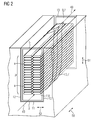
- FIG. 2 shows a second embodiment of the proposed fluid-cooled active part 1.
- the same reference numerals as in FIG. 1 denote the same objects.
- the active part 1 of the second embodiment is characterized i.a. characterized in that a defined flow direction 43 is specified for the fluid within the respective groove 2.
- the respective cooling channel 7 comprises an inlet channel 8, an outlet channel 9 and a respective connecting channel 10, which fluidly connects the inlet channel 8 with the outlet channel 9.
- the inlet channel 8 between the electrical conductor 3 and the groove bottom 11 and the outlet channel 9 between the respective conductor and the slot opening 13 are arranged.
- the respective connecting channel 10 is predominantly arranged between the conductor 3 and one of the two groove walls 12.
- FIG. 3 shows a third embodiment of the proposed fluid-cooled active part 1, wherein a section of a cross section perpendicular to the axial direction 50 is shown by the active part 1.
- two electrical conductors 3A, 3B are provided in the respective groove 2, which are arranged one above the other in the radial direction 51.
- the conductor 3A is the upper conductor facing the slot opening 13 and the conductor 3B is the lower conductor facing the groove base 11.
- only one of the two conductors 3A, 3B may be provided.
- Each of the two conductors 3A, 3B is associated with a respective main insulation 5, which each have two substantially C-shaped Insulating half shells 14 has.
- the two respective insulating half shells 14 enclose together the respective conductor 3A, 3B in a plane perpendicular to the axial direction 50.
- the two insulating half shells 14 are arranged substantially symmetrically to the groove center 15 in the circumferential direction 52 of the respective groove 2.
- the two respective insulating half-shells 14 are sealed by means of a respective sealing element 16, the respective sealing element 16 in particular having a fluorine rubber.
- an inlet channel 8 and an outlet channel 9 are arranged within a pair of insulating half-shells 14.
- the respective insulating half-shell 14 in the region of support or contact lines each have a kind of hook 44 which in the radial direction 51 to the respective conductor 3A, 3B has.
- the mentioned sealing element 16 is, as in FIG. 3 indicated between two hooks 44 of two mating insulating shells 14.
- the hooks 44 are to be regarded as optional.
- Equally optional is a spacer 45, which is arranged between the plurality of sub-conductor 4 and the respective insulating half-shell 14, which, however, creates space for the respective connecting channel 10 within the scope of the exemplary embodiment.
- radial direction 51 may be provided between the insulating half-shells 14 of the upper conductor 3A and the lower conductor 3B, an unspecified intermediate element for sealing or tolerance compensation.
- FIGS. 4 to 8 show a fourth embodiment of the proposed fluid-cooled active part 1, wherein the FIGS. 6 and 7 illustrate some details and otherwise a perspective section of a cross-section perpendicular to the axial direction 50 is shown by the active part 1.
- two electrical conductors 3A, 3B are provided in the respective groove 2, which are arranged one above the other in the radial direction 51.
- the conductor 3A is the upper conductor facing the slot opening 13 and the conductor 3B is the lower conductor facing the groove base 11.
- only one of the two conductors 3A, 3B may be provided.
- the respective main insulation 5 is designed such that it largely covers the groove base 11 and the two groove walls 12 of the respective groove 2.
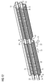
- a plurality of channel half-shells 17 are arranged one behind the other in the axial direction 50, wherein some of the channel half shells 17 are mirror-inverted to other of the channel half shells 17 with respect to the groove center 15 in the circumferential direction 52 of the respective groove 2.
- the respective channel half-shell 17 has a substantially U-shaped cross section in a plane perpendicular to the axial direction 50 and largely encloses the respective conductor 3A, 3B.
- the respective channel half-shell 17 has, viewed in a plane perpendicular to the axial direction 50, a radial web 18 and two pairs of peripheral webs 19.
- the respective radial web 18 extends in the radial direction along the respective conductor 3 and the respective peripheral web 19 points in the circumferential direction 52, wherein the peripheral webs 19 are connected by means of the radial web 18.
- the respective inlet channel 8 and the respective outlet channel 9 are configured as follows. In the area of that pair of circumferential webs 19 which are closer to the groove base 11 (ie in the FIGS. 4 to 8 Below), the inlet channel 8 is arranged and in the region of that pair of peripheral webs 19, which closer to the slot opening 13 (ie in the FIGS. 4 to 8 Above), the outlet channel 9 is arranged.
- the active part 1 in this case has first channel half shells 17A, which, as in FIG. 7 illustrated, have central circumferential webs 19 having a respective passage opening 20 (upper of the central peripheral webs 19 in FIG. 7 ) or form a respective passage opening 20 which remains between the respective central circumferential ridge 19 and the respective main insulation 5 (lower of the central peripheral ridges 19 in FIG FIG. 7 ).
- the latter embodiment is achieved in that the corresponding peripheral web 19 is configured somewhat shorter in the circumferential direction than the remaining peripheral webs 19 and thus the passage opening 20 is formed.
- at least one part of the respective connecting channel 10 is configured by means of at least one of the two central circumferential webs 19.
- the respective first channel half-shell 17A may have or form only one through-opening 20 or two similar ones of the illustrated through-openings 20.
- the active part 1 has second channel half-shells 17B, in each of which the circumferential webs 19 of one pair or both pairs of circumferential webs 19 are connected by means of a respective end web 21, as in FIG FIG. 6 is shown.
- the second channel half shells 17B are configured in such a way that, viewed in a plane perpendicular to the axial direction 50, they each have a rectangular cross section for guiding the respective cooling channel 7.
- two such rectangular cross sections are formed, one for the inlet channel 8 and one for the outlet channel 9.
- an intermediate element 22 provided for sealing or tolerance compensation.
- the fluid is introduced into the respective inlet channel 8 and is there first performed in the axial direction 50 by means of the second channel half shells 17B. Subsequently, the fluid is guided by means of the first channel half shells 17A through corresponding passage openings 20 in the radial direction 51 in the respective connecting channel 10, to then be directed into the respective outlet channel 9 and finally in the axial direction 15 from the arrangement of the channel half shells 17th to be led out.
- FIGS. 9 to 12 show a fifth embodiment of the proposed fluid-cooled active part 1, wherein a cutout or a perspective section of a cross-section perpendicular to the axial direction 50 is shown by the active part 1 and in FIG. 10 Details of a conductor shell 23 for an upper electrical conductor 3A are shown.
- two electrical conductors 3A, 3B are provided in the respective groove 2, which are arranged one above the other in the radial direction 51.
- the conductor 3A is the upper conductor facing the slot opening 13 and the conductor 3B is the lower conductor facing the groove base 11.
- only one of the two conductors 3A, 3B may be provided.
- the respective main insulation 5 is designed such that it largely covers the groove base 11 and the two groove walls 12 of the respective groove 2.
- a respective conductor shell 23 is provided, which encloses the respective conductor 3A, 3B in a plane perpendicular to the axial direction 50.
- the respective groove 2 has a groove region 47, along which the groove width 28 decreases in the radial direction 51 towards the groove base 11, so that the respective groove 2 tapers there towards the groove base 11.
- the respective conductor shell 23 of the lower conductor 3B tapers in the corresponding area also towards the groove base 11, wherein the respective tapers are configured such that the respective conductor shell 23 of the lower conductor 3B is positively fixed to the groove base 11 and between the groove bottom 11 and the respective conductor shell 23 of the lower conductor 3 B, a first, axially extending cavity 24 for the first inlet channel 8A remains.
- the groove width 28 in the region of the first cavity 24 can remain constant.
- a respective first insert part 25 which has a H-shaped cross-section in a plane perpendicular to the axial direction 50.
- the respective first insert part 25 is arranged between the respective conductor shell 23 of the lower conductor 3B and the respective conductor shell 23 of the upper electrical conductor 3A.
- the respective first insert part 25 is configured such that a second, axially extending cavity 26 for a first outlet channel 9A remains between the respective conductor shell 23 of the lower conductor 3B on the one hand and the respective first insert part 25 on the other hand.
- a third, axially extending cavity 27 for a second inlet channel 8B remains between the respective conductor shell 23 of the upper conductor 3A on the one hand and the respective first insert part 25 on the other hand.
- the respective first insert part 25 has two outer webs 29 which point towards the slot opening 13 and are arranged in sections in the circumferential direction 52 between the respective conductor shell 23 of the upper conductor 3A on the one hand and the respective groove wall 12 on the other hand are.
- the two outer webs 29 of the respective first insert 25 are tapered towards the slot opening 13 and the respective conductor shell 23 of the upper conductor 3A tapers in sections toward the groove bottom 11, wherein the tapers are configured such that the respective conductor shell 23 of the upper conductor 3A is fixed non-positively in the radial direction 51.
- a respective second insert 30 is provided, which in each case in a plane perpendicular to the axial direction 50 has a U-shaped cross-section.
- the respective second insert part 30 is arranged and configured such that a fourth, axially extending cavity 31 for a second outlet channel 9B remains between the respective conductor shell 23 of the upper conductor 3A on the one hand and the respective second insert part 30 on the other hand.
- the respective second insert part 30 has, in a plane perpendicular to the axial direction 50, two inner webs 32 facing the groove base 11 and arranged in sections in the circumferential direction between the respective conductor shell 23 of the upper conductor 3A on the one hand and the respective groove wall 12 on the other hand ,
- the two inner webs 32 of the respective second insert 30 taper towards the groove bottom 11, with the respective conductor shell 23 of the upper conductor 3A tapering in sections towards the slot opening 13.
- the tapers are configured in such a way that the respective conductor shell 23 of the upper conductor 3A and the respective second insert part 30 are fixed non-positively in the radial direction 51.
- the respective conductor shell 23 is configured in two parts by comprising a first conductor shell part 23A, which essentially has a U-shaped cross section in a plane perpendicular to the axial direction 50, and a second conductor shell part 23B, like in the Figures 9 and 10 is shown.
- the second conductor shell part 23B is designed as a kind of cover for the first conductor shell part 23A.
- the second conductor shell part 23B has two grooves and the first conductor shell part 23A shows two corresponding springs for a respective tongue and groove connection.
- a fluororubber can be used in the region of the tongue and groove connection on the basis of its advantageous properties explained above
- two respective inserts 15, 30 in the axial direction 50 are arranged behind one another in the context of the embodiment, wherein in the region of the axial center between the two respective inserts 25, 30 a respective axial gap 33 remains.
- the first cavity 24 and the third cavity 27 are closed in the region of the axial center by means of a respective cover 34.
- Further covers 34 are provided for closing the second cavity 26 and the fourth cavity 31 at the respective axial end face.
- the respective conductor shell 23 has recesses 35 which extend in the radial direction 51 and form the respective connection channel 10.
- no such recesses 35 are provided in the respective conductor shell 23 in the immediate vicinity of the respective axial end face. Similarly, no such recesses 35 are provided in the respective conductor shell 23 in the immediate vicinity of the illustrated gap 33.
- FIG. 13 shows an embodiment of the proposed electric machine 38 and the proposed drive system 41, wherein a cross section has long been the axial direction 50 is shown.
- the electric machine 38 has a stator 39 and a rotatably mounted rotor 40, wherein the stator 39 and / or the rotor 40 are designed as the proposed, fluid-cooled active part.
- the electric machine 38 can be operated with an electrical voltage in the range of a few kV, in particular a few 10 kV.
- the electric machine 38 is part of the drive system 41, which furthermore has a fluid energy machine 42 for the fluid, wherein the fluid energy machine 42 is designed as a compressor, in particular for a process gas, or as a pump, in particular for a process fluid.
- the arrows 43 indicate the flows of the fluid in the electric machine 38 and in the fluid energy machine 42.
- the invention relates to a fluid-cooled active part for an electric machine, wherein the active part is configured substantially cylindrical or hollow cylindrical, having axially extending grooves, at least one electrical conductor which is at least partially disposed in the respective groove and which consists of a plurality of Partial conductors composed of a respective main insulation, which is arranged between the respective conductor and the respective groove, and a respective sub-conductor insulation, which surrounds the respective sub-conductor.
- the invention relates to an electrical machine comprising such a configured as a stator, fluid-cooled active part and / or such, designed as a rotatably mounted rotor ausgestaltetes, fluid-cooled active part, wherein the electric machine with an electrical voltage in the range of at least a few kV, preferably some 10th kV, is operable.
- the invention relates to a drive system comprising such an electric machine and a fluid energy machine for the fluid, wherein the fluid energy machine, for example.
- a compressor or, in particular for a process gas, or as a pump, in particular for a process liquid is configured.
- the active part a respective cooling channel for guiding the fluid, in particular a process fluid, wherein the respective cooling channel is arranged between the respective main insulation and the respective sub-conductor insulation. Furthermore, a corresponding electric machine and a corresponding drive system are proposed.
Landscapes
- Engineering & Computer Science (AREA)
- Power Engineering (AREA)
- Motor Or Generator Cooling System (AREA)
Priority Applications (6)
| Application Number | Priority Date | Filing Date | Title |
|---|---|---|---|
| EP16161663.6A EP3223394A1 (fr) | 2016-03-22 | 2016-03-22 | Piece active refroidie par liquide, machine electrique et systeme d'entrainement |
| US16/087,607 US11289975B2 (en) | 2016-03-22 | 2017-01-24 | Fluid-cooled active part, electric machine, and drive system |
| PCT/EP2017/051388 WO2017162348A1 (fr) | 2016-03-22 | 2017-01-24 | Partie active refroidie par fluide, machine électrique et système d'entraînement |
| EP17702559.0A EP3433920B1 (fr) | 2016-03-22 | 2017-01-24 | Piece active refroidie par liquide, machine electrique et systeme d'entrainement |
| CN201780019564.1A CN108886282B (zh) | 2016-03-22 | 2017-01-24 | 流体冷却主动部件、电机和驱动系统 |
| RU2018133483A RU2706349C1 (ru) | 2016-03-22 | 2017-01-24 | Охлаждаемая текучей средой активная часть, электрическая машина и приводная система |
Applications Claiming Priority (1)
| Application Number | Priority Date | Filing Date | Title |
|---|---|---|---|
| EP16161663.6A EP3223394A1 (fr) | 2016-03-22 | 2016-03-22 | Piece active refroidie par liquide, machine electrique et systeme d'entrainement |
Publications (1)
| Publication Number | Publication Date |
|---|---|
| EP3223394A1 true EP3223394A1 (fr) | 2017-09-27 |
Family
ID=55588132
Family Applications (2)
| Application Number | Title | Priority Date | Filing Date |
|---|---|---|---|
| EP16161663.6A Withdrawn EP3223394A1 (fr) | 2016-03-22 | 2016-03-22 | Piece active refroidie par liquide, machine electrique et systeme d'entrainement |
| EP17702559.0A Active EP3433920B1 (fr) | 2016-03-22 | 2017-01-24 | Piece active refroidie par liquide, machine electrique et systeme d'entrainement |
Family Applications After (1)
| Application Number | Title | Priority Date | Filing Date |
|---|---|---|---|
| EP17702559.0A Active EP3433920B1 (fr) | 2016-03-22 | 2017-01-24 | Piece active refroidie par liquide, machine electrique et systeme d'entrainement |
Country Status (5)
| Country | Link |
|---|---|
| US (1) | US11289975B2 (fr) |
| EP (2) | EP3223394A1 (fr) |
| CN (1) | CN108886282B (fr) |
| RU (1) | RU2706349C1 (fr) |
| WO (1) | WO2017162348A1 (fr) |
Cited By (9)
| Publication number | Priority date | Publication date | Assignee | Title |
|---|---|---|---|---|
| US20200161916A1 (en) * | 2018-11-19 | 2020-05-21 | Mahle International Gmbh | Electrical machine, in particular for a vehicle |
| WO2020104425A1 (fr) * | 2018-11-19 | 2020-05-28 | Mahle International Gmbh | Corps isolant pour machine électrique |
| WO2021032238A1 (fr) * | 2019-08-21 | 2021-02-25 | Schaeffler Technologies AG & Co. KG | Refroidissement de stator |
| CN112585845A (zh) * | 2018-06-27 | 2021-03-30 | 通用电气公司 | 用于具有超导定子的风力涡轮发电机的旋转电枢 |
| EP3955424A1 (fr) * | 2020-08-10 | 2022-02-16 | Siemens Aktiengesellschaft | Machine dynamoélectrique à refroidissement par liquide |
| WO2022073536A1 (fr) * | 2020-10-07 | 2022-04-14 | Schaeffler Technologies AG & Co. KG | Machine électrique |
| EP4102684A1 (fr) * | 2021-06-08 | 2022-12-14 | Dr. Ing. h.c. F. Porsche Aktiengesellschaft | Stator pour une machine électrique, machine électrique, véhicule automobile |
| EP4238206A4 (fr) * | 2020-10-27 | 2024-10-23 | Tau Motors, Inc. | Système et procédé de gestion thermique de machines électroniques à l'aide de bidons de liquide de refroidissement |
| WO2025214547A1 (fr) * | 2024-04-11 | 2025-10-16 | Schaeffler Technologies AG & Co. KG | Ensemble rotor, corps de séparation et procédé de production d'un corps de séparation |
Families Citing this family (15)
| Publication number | Priority date | Publication date | Assignee | Title |
|---|---|---|---|---|
| DE102018101640B4 (de) | 2018-01-25 | 2020-11-26 | ATE Antriebstechnik und Entwicklungs GmbH & Co. KG | Elektrische Antriebsvorrichtung |
| US11258325B2 (en) | 2018-10-23 | 2022-02-22 | General Electric Company | Articles including insulated conductors and systems thereof |
| DE102018219816A1 (de) * | 2018-11-19 | 2020-05-20 | Mahle International Gmbh | Elektrische Maschine, insbesondere für ein Fahrzeug |
| DE102018219820A1 (de) * | 2018-11-19 | 2020-06-04 | Mahle International Gmbh | Isolationskörper für eine elektrische Maschine |
| GB201907642D0 (en) * | 2019-05-30 | 2019-07-17 | Cummins Generator Technologies | Rotor cooling |
| EP3820025B1 (fr) * | 2019-11-08 | 2025-10-15 | Hamilton Sundstrand Corporation | Espaceur pour un enroulement de stator |
| US11764629B2 (en) | 2020-12-23 | 2023-09-19 | Delta Electronics, Inc. | In-slot cooling system for an electric machine with hairpin windings |
| DE102021107454B4 (de) * | 2021-03-25 | 2023-02-02 | Dr. Ing. H.C. F. Porsche Aktiengesellschaft | Statoreinrichtung für eine elektrische Maschine und Verfahren zur Herstellung |
| DE102021108957A1 (de) | 2021-04-10 | 2022-10-13 | Schaeffler Technologies AG & Co. KG | Elektrische Maschine |
| DE102021113691A1 (de) * | 2021-05-27 | 2022-12-01 | Dr. Ing. H.C. F. Porsche Aktiengesellschaft | Stator einer elektrischen Antriebsmaschine und Verfahren zum Herstellen desselben |
| DE102021115932A1 (de) * | 2021-06-21 | 2022-12-22 | Dr. Ing. H.C. F. Porsche Aktiengesellschaft | Stator einer elektrischen Maschine und elektrische Maschine |
| DE102021210278A1 (de) | 2021-09-16 | 2023-03-16 | Volkswagen Aktiengesellschaft | Verfahren zur Flüssigkeitsabdichtung einer Statornut eines Stators einer elektrischen Maschine und elektrische Maschine |
| DE102024101873A1 (de) * | 2024-01-23 | 2025-07-24 | Bayerische Motoren Werke Aktiengesellschaft | Anordnung einer Wicklung an einem Blechpaket für eine elektrische Maschine, Verfahren zum Herstellen eines Stators oder eines Rotors für eine elektrische Maschine, Stator für eine elektrische Maschine, Rotor für eine elektrische Maschine sowie elektrische Maschine |
| DE102024104526A1 (de) | 2024-02-19 | 2025-08-21 | Bayerische Motoren Werke Aktiengesellschaft | Fixierungsvorrichtung für ein Aktivteil einer elektrischen Traktionsmaschine, Stator für eine elektrische Traktionsmaschine sowie Kraftfahrzeug |
| FR3161820A1 (fr) * | 2024-04-29 | 2025-10-31 | Valeo Eautomotive Germany Gmbh | Machine électrique tournante |
Citations (11)
| Publication number | Priority date | Publication date | Assignee | Title |
|---|---|---|---|---|
| GB172939A (en) * | 1920-12-16 | 1922-08-03 | Bbc Brown Boveri & Cie | Improvements in the high-voltage slot-windings of electrical machines and in the process for the manufacture of same |
| GB720295A (en) * | 1951-12-12 | 1954-12-15 | Vickers Electrical Co Ltd | Improvements relating to the construction of dynamo electric machines |
| GB722152A (en) * | 1951-09-28 | 1955-01-19 | Westinghouse Electric Int Co | Improvements in or relating to dynamo electric machines |
| CH332979A (de) * | 1955-08-16 | 1958-09-30 | Bbc Brown Boveri & Cie | Statorwicklungsstab für Turbogeneratoren |
| EP0026099A1 (fr) * | 1979-09-25 | 1981-04-01 | Westinghouse Electric Corporation | Machine dynamoélectrique avec enroulement d'excitation cryostable |
| EP1863152A2 (fr) | 2006-06-02 | 2007-12-05 | General Electric Company | Procédés et appareil pour l'utilisation d'une machine électrique pour le transport de fluides dans une conduite |
| DE102009003424A1 (de) | 2008-02-04 | 2009-08-13 | General Electric Co. | Hochfrequenzelektroantrieb mit Multipolmotor für Gaspipeline-und Speicherkompressionsanwendungen |
| US20100264761A1 (en) | 2009-04-09 | 2010-10-21 | Converteam Technology Ltd. | Coil for a rotating electrical machine |
| EP2267869B1 (fr) | 2009-06-25 | 2012-10-24 | General Electric Company | Ensemble de scellement hermétique et dispositif électrique l'incluant |
| EP1967286B1 (fr) | 2007-03-08 | 2014-05-21 | General Electric Company | Ensemble de stator encapsulé et processus de fabrication |
| WO2015021977A2 (fr) * | 2013-08-13 | 2015-02-19 | Schaeffler Technologies Gmbh & Co. Kg | Dispositif de transfert de chaleur, et module enroulement formé en intégrant ce dispositif |
Family Cites Families (12)
| Publication number | Priority date | Publication date | Assignee | Title |
|---|---|---|---|---|
| CA591705A (en) * | 1954-12-28 | 1960-02-02 | M. Willyoung David | Dynamoelectric machine conductor with internal fluid cooling passages |
| US2873393A (en) * | 1957-03-28 | 1959-02-10 | Westinghouse Electric Corp | Dual-ventilation hydrogen-cooled generators |
| US3624432A (en) * | 1969-12-19 | 1971-11-30 | Bbc Brown Boveri & Cie | Arrangement for securing electrical conductor bars within slots to prevent vibration |
| FR2121981A5 (fr) * | 1971-01-13 | 1972-08-25 | Alsthom | |
| US4602180A (en) * | 1985-01-07 | 1986-07-22 | General Electric Company | Insulated armature coil for dynamoelectric machine |
| US7183678B2 (en) * | 2004-01-27 | 2007-02-27 | General Electric Company | AC winding with integrated cooling system and method for making the same |
| US7679242B2 (en) | 2007-10-03 | 2010-03-16 | Baker Hughes Incorporated | Shrink tube encapsulated magnet wire for electrical submersible motors |
| US20100090549A1 (en) * | 2008-10-10 | 2010-04-15 | General Electric Company | Thermal management in a fault tolerant permanent magnet machine |
| US20130002067A1 (en) | 2011-06-30 | 2013-01-03 | Bradfield Michael D | Electric Machine Module Cooling System and Method |
| US20160036277A1 (en) * | 2014-08-04 | 2016-02-04 | Hamilton Sundstrand Corporation | Strand cross-section for high fill-factor electric machine windings |
| DE102017101094A1 (de) * | 2017-01-20 | 2018-07-26 | Dr. Ing. H.C. F. Porsche Aktiengesellschaft | Vorrichtung zur Abdichtung mehrerer Nuten eines Stators einer elektrischen Antriebsmaschine |
| US10784746B2 (en) * | 2017-06-15 | 2020-09-22 | General Electric Company | Systems and method for embedded direct winding cooling for electric machines |
-
2016
- 2016-03-22 EP EP16161663.6A patent/EP3223394A1/fr not_active Withdrawn
-
2017
- 2017-01-24 WO PCT/EP2017/051388 patent/WO2017162348A1/fr not_active Ceased
- 2017-01-24 CN CN201780019564.1A patent/CN108886282B/zh active Active
- 2017-01-24 US US16/087,607 patent/US11289975B2/en active Active
- 2017-01-24 EP EP17702559.0A patent/EP3433920B1/fr active Active
- 2017-01-24 RU RU2018133483A patent/RU2706349C1/ru active
Patent Citations (11)
| Publication number | Priority date | Publication date | Assignee | Title |
|---|---|---|---|---|
| GB172939A (en) * | 1920-12-16 | 1922-08-03 | Bbc Brown Boveri & Cie | Improvements in the high-voltage slot-windings of electrical machines and in the process for the manufacture of same |
| GB722152A (en) * | 1951-09-28 | 1955-01-19 | Westinghouse Electric Int Co | Improvements in or relating to dynamo electric machines |
| GB720295A (en) * | 1951-12-12 | 1954-12-15 | Vickers Electrical Co Ltd | Improvements relating to the construction of dynamo electric machines |
| CH332979A (de) * | 1955-08-16 | 1958-09-30 | Bbc Brown Boveri & Cie | Statorwicklungsstab für Turbogeneratoren |
| EP0026099A1 (fr) * | 1979-09-25 | 1981-04-01 | Westinghouse Electric Corporation | Machine dynamoélectrique avec enroulement d'excitation cryostable |
| EP1863152A2 (fr) | 2006-06-02 | 2007-12-05 | General Electric Company | Procédés et appareil pour l'utilisation d'une machine électrique pour le transport de fluides dans une conduite |
| EP1967286B1 (fr) | 2007-03-08 | 2014-05-21 | General Electric Company | Ensemble de stator encapsulé et processus de fabrication |
| DE102009003424A1 (de) | 2008-02-04 | 2009-08-13 | General Electric Co. | Hochfrequenzelektroantrieb mit Multipolmotor für Gaspipeline-und Speicherkompressionsanwendungen |
| US20100264761A1 (en) | 2009-04-09 | 2010-10-21 | Converteam Technology Ltd. | Coil for a rotating electrical machine |
| EP2267869B1 (fr) | 2009-06-25 | 2012-10-24 | General Electric Company | Ensemble de scellement hermétique et dispositif électrique l'incluant |
| WO2015021977A2 (fr) * | 2013-08-13 | 2015-02-19 | Schaeffler Technologies Gmbh & Co. Kg | Dispositif de transfert de chaleur, et module enroulement formé en intégrant ce dispositif |
Cited By (14)
| Publication number | Priority date | Publication date | Assignee | Title |
|---|---|---|---|---|
| CN112585845B (zh) * | 2018-06-27 | 2024-04-26 | 通用电气可再生能源西班牙有限公司 | 用于具有超导定子的风力涡轮发电机的旋转电枢 |
| CN112585845A (zh) * | 2018-06-27 | 2021-03-30 | 通用电气公司 | 用于具有超导定子的风力涡轮发电机的旋转电枢 |
| US12206306B2 (en) * | 2018-11-19 | 2025-01-21 | Mahle International Gmbh | Electrical machine, in particular for a vehicle with a cooling channel for cooling stator windings |
| WO2020104425A1 (fr) * | 2018-11-19 | 2020-05-28 | Mahle International Gmbh | Corps isolant pour machine électrique |
| US20200161916A1 (en) * | 2018-11-19 | 2020-05-21 | Mahle International Gmbh | Electrical machine, in particular for a vehicle |
| WO2021032238A1 (fr) * | 2019-08-21 | 2021-02-25 | Schaeffler Technologies AG & Co. KG | Refroidissement de stator |
| EP3955424A1 (fr) * | 2020-08-10 | 2022-02-16 | Siemens Aktiengesellschaft | Machine dynamoélectrique à refroidissement par liquide |
| WO2022034105A1 (fr) | 2020-08-10 | 2022-02-17 | Flender Gmbh | Éolienne ayant au moins une machine dynamo-électrique |
| US11885312B2 (en) | 2020-08-10 | 2024-01-30 | Flender Gmbh | Wind turbine with at least one dynamoelectric machine with cooling channel in winding insulation and can |
| WO2022073536A1 (fr) * | 2020-10-07 | 2022-04-14 | Schaeffler Technologies AG & Co. KG | Machine électrique |
| EP4238206A4 (fr) * | 2020-10-27 | 2024-10-23 | Tau Motors, Inc. | Système et procédé de gestion thermique de machines électroniques à l'aide de bidons de liquide de refroidissement |
| US12407206B2 (en) | 2021-06-08 | 2025-09-02 | Dr. Ing. H.C. F. Porsche Aktiengesellschaft | Stator for electric machine, electric machine, and motor vehicle |
| EP4102684A1 (fr) * | 2021-06-08 | 2022-12-14 | Dr. Ing. h.c. F. Porsche Aktiengesellschaft | Stator pour une machine électrique, machine électrique, véhicule automobile |
| WO2025214547A1 (fr) * | 2024-04-11 | 2025-10-16 | Schaeffler Technologies AG & Co. KG | Ensemble rotor, corps de séparation et procédé de production d'un corps de séparation |
Also Published As
| Publication number | Publication date |
|---|---|
| EP3433920B1 (fr) | 2020-07-01 |
| RU2706349C1 (ru) | 2019-11-18 |
| WO2017162348A1 (fr) | 2017-09-28 |
| US11289975B2 (en) | 2022-03-29 |
| EP3433920A1 (fr) | 2019-01-30 |
| US20190109513A1 (en) | 2019-04-11 |
| CN108886282B (zh) | 2020-09-18 |
| CN108886282A (zh) | 2018-11-23 |
Similar Documents
| Publication | Publication Date | Title |
|---|---|---|
| EP3433920B1 (fr) | Piece active refroidie par liquide, machine electrique et systeme d'entrainement | |
| DE3916253C2 (fr) | ||
| DE102013211408B4 (de) | Kühleinrichtung zur Kühlung einer elektrischen Maschine und entsprechende elektrische Maschine mit Kühleinrichtung | |
| DE102006005316B4 (de) | Kühleinrichtung für eine elektrische Maschine, elektrische Maschinen mit einer solchen Kühleinrichtung, Dynamoblech sowie Herstellungsverfahren für solche elektrischen Maschinen | |
| DE602004005235T2 (de) | Verbesserte kühlung eines elektromotors oder generators | |
| DE102013204047B4 (de) | Elektrische Einrichtung mit einer Spule | |
| DE102015207865A1 (de) | Gehäuselose elektrische Maschine | |
| DE102011084296A1 (de) | Gehäuseelement, Statorelement und diesbezügliche Anordnung für eine elektrische Maschine | |
| DE102012207888A1 (de) | Stator für einen Elektromotor | |
| DE102019120824A1 (de) | Spaltrohrmotor mit abstützender Dichtung | |
| EP2499721B1 (fr) | Machine électrique, en particulier moteur électrique à gaine | |
| DE102018131962A1 (de) | Kühlkanal für einen Wickelkopf eines Stators und Stator mit einem derartigen Kühlkanal | |
| WO2006042832A1 (fr) | Boitier pour machine electrique comprenant des canaux de refroidissement qui s'etendent dans une paroi du boitier | |
| DE102009038246B4 (de) | Dichtungen für Getriebeantriebsmotoren | |
| EP0519091A1 (fr) | Machine électrique refroidie par un gaz | |
| EP2365614A2 (fr) | Moteur à gaine avec support de gaine | |
| WO2001063725A1 (fr) | Machine a rotation haute tension et procede de refroidissement des conducteurs de cette machine | |
| DE202005021025U1 (de) | Gekühlte elektrodynamische Maschine mit einem Spaltrohr | |
| DE102022109799A1 (de) | Elektrische Maschine mit einem Stator | |
| EP3431769B1 (fr) | Pompe à vide | |
| DE112024001796T5 (de) | Stator | |
| EP4625766A1 (fr) | Moteur et système d'alimentation de véhicule | |
| EP2022950B1 (fr) | Turbomachine ou machine de refoulement | |
| DE102015222748A1 (de) | Adaptive Dichtungsanordnung sowie Lageranordnung mit adaptiver Dichtungsanordnung | |
| DE102018206401A1 (de) | Elektromotor und Verfahren zur Herstellung desselben |
Legal Events
| Date | Code | Title | Description |
|---|---|---|---|
| PUAI | Public reference made under article 153(3) epc to a published international application that has entered the european phase |
Free format text: ORIGINAL CODE: 0009012 |
|
| AK | Designated contracting states |
Kind code of ref document: A1 Designated state(s): AL AT BE BG CH CY CZ DE DK EE ES FI FR GB GR HR HU IE IS IT LI LT LU LV MC MK MT NL NO PL PT RO RS SE SI SK SM TR |
|
| AX | Request for extension of the european patent |
Extension state: BA ME |
|
| STAA | Information on the status of an ep patent application or granted ep patent |
Free format text: STATUS: THE APPLICATION IS DEEMED TO BE WITHDRAWN |
|
| 18D | Application deemed to be withdrawn |
Effective date: 20180328 |