EP3223441A1 - Satellite de communication à grande capacité utilisant une formation de faisceau optique passive - Google Patents
Satellite de communication à grande capacité utilisant une formation de faisceau optique passive Download PDFInfo
- Publication number
- EP3223441A1 EP3223441A1 EP17162200.4A EP17162200A EP3223441A1 EP 3223441 A1 EP3223441 A1 EP 3223441A1 EP 17162200 A EP17162200 A EP 17162200A EP 3223441 A1 EP3223441 A1 EP 3223441A1
- Authority
- EP
- European Patent Office
- Prior art keywords
- optical
- signals
- multiplicity
- recited
- processing system
- Prior art date
- Legal status (The legal status is an assumption and is not a legal conclusion. Google has not performed a legal analysis and makes no representation as to the accuracy of the status listed.)
- Granted
Links
Images




Classifications
-
- H—ELECTRICITY
- H04—ELECTRIC COMMUNICATION TECHNIQUE
- H04B—TRANSMISSION
- H04B7/00—Radio transmission systems, i.e. using radiation field
- H04B7/14—Relay systems
- H04B7/15—Active relay systems
- H04B7/185—Space-based or airborne stations; Stations for satellite systems
- H04B7/1851—Systems using a satellite or space-based relay
- H04B7/18515—Transmission equipment in satellites or space-based relays
-
- H—ELECTRICITY
- H01—ELECTRIC ELEMENTS
- H01Q—ANTENNAS, i.e. RADIO AERIALS
- H01Q3/00—Arrangements for changing or varying the orientation or the shape of the directional pattern of the waves radiated from an antenna or antenna system
- H01Q3/26—Arrangements for changing or varying the orientation or the shape of the directional pattern of the waves radiated from an antenna or antenna system varying the relative phase or relative amplitude of energisation between two or more active radiating elements; varying the distribution of energy across a radiating aperture
- H01Q3/2676—Optically controlled phased array
-
- H—ELECTRICITY
- H01—ELECTRIC ELEMENTS
- H01Q—ANTENNAS, i.e. RADIO AERIALS
- H01Q3/00—Arrangements for changing or varying the orientation or the shape of the directional pattern of the waves radiated from an antenna or antenna system
- H01Q3/26—Arrangements for changing or varying the orientation or the shape of the directional pattern of the waves radiated from an antenna or antenna system varying the relative phase or relative amplitude of energisation between two or more active radiating elements; varying the distribution of energy across a radiating aperture
- H01Q3/2682—Time delay steered arrays
-
- H—ELECTRICITY
- H04—ELECTRIC COMMUNICATION TECHNIQUE
- H04B—TRANSMISSION
- H04B10/00—Transmission systems employing electromagnetic waves other than radio-waves, e.g. infrared, visible or ultraviolet light, or employing corpuscular radiation, e.g. quantum communication
- H04B10/11—Arrangements specific to free-space transmission, i.e. transmission through air or vacuum
- H04B10/118—Arrangements specific to free-space transmission, i.e. transmission through air or vacuum specially adapted for satellite communication
-
- H—ELECTRICITY
- H01—ELECTRIC ELEMENTS
- H01Q—ANTENNAS, i.e. RADIO AERIALS
- H01Q3/00—Arrangements for changing or varying the orientation or the shape of the directional pattern of the waves radiated from an antenna or antenna system
-
- H—ELECTRICITY
- H04—ELECTRIC COMMUNICATION TECHNIQUE
- H04B—TRANSMISSION
- H04B2210/00—Indexing scheme relating to optical transmission systems
- H04B2210/006—Devices for generating or processing an RF signal by optical means
-
- H—ELECTRICITY
- H04—ELECTRIC COMMUNICATION TECHNIQUE
- H04B—TRANSMISSION
- H04B7/00—Radio transmission systems, i.e. using radiation field
- H04B7/14—Relay systems
- H04B7/15—Active relay systems
- H04B7/185—Space-based or airborne stations; Stations for satellite systems
- H04B7/18502—Airborne stations
- H04B7/18506—Communications with or from aircraft, i.e. aeronautical mobile service
- H04B7/18508—Communications with or from aircraft, i.e. aeronautical mobile service with satellite system used as relay, i.e. aeronautical mobile satellite service
Definitions
- the technology disclosed herein generally relates to communications satellite systems and methods, and more particularly relates to the broadcast of signals on a local-area basis with some of the signal frequency bands being repeated for different areas.
- spot broadcast beams which are smaller than regional beams, have been used for satellite broadcasting.
- a desired region such as a country
- spot beam broadcast a desired region, such as a country
- a uniform grid of evenly spaced spot beams having equal sizes and output power levels.
- adjacent beam spots are overlapped.
- Different and non-overlapping frequency bands are assigned to the signals within each pair of adjacent beams to prevent cross-beam signal interference.
- four different frequency bands are employed, with each beam being separated from the next closest beam with the same frequency band by at least one other beam having a different frequency band.
- the uniform spot beams provide complete coverage of the desired larger regional area without significant interference between beams.
- Uplink and downlink antennas may be implemented with any conventional antennas used in satellite communications.
- antennas are implemented with digital or analog beamforming antennas having any number of independently-addressable transmit/receive elements. Examples of such antennas include various spot beam dishes, multi-beam feed antennas, direct radiating array antennas and/or phased array antennas which are commercially available.
- the optical beamforming is achieved utilizing active units. These units often include lasers, optical receivers and MEMS switching networks. These active units consume large amounts of the satellite's power and mass resources. Active units also greatly reduce the satellite's reliability.
- a communications satellite system that uses passive rather than active optical components to process optical beams received from a ground station would be a welcome advance in the art.
- the subject matter disclosed in detail below is directed to a communications satellite system that provides one terabit/second throughput utilizing passive optical beamforming networks. This greatly reduces the demand on the satellite's power and mass resources, in addition to increasing the reliability of the communications system. Additionally, the disclosed communications satellite system utilizes a method for optically selecting the desired satellite spot beam antenna from which the communications signal will be transmitted. As is the case for beamforming, the beam selection function uses only passive optical components rather than mechanical or electrical optical switches.
- an onboard telescope receives optical beams uplinked from a ground-based gateway.
- the receiver telescope couples the uplinked beams into an onboard optical signal processing system via an optical waveguide.
- the onboard optical signal processing system comprises a passive optical demultiplexer, a multiplicity of passive single-sideband (SSB) filters, and a multiplicity of passive optical beamforming networks.
- the passive optical demultiplexer splits the incoming optical signal into a multiplicity of frequency bandwidths.
- the optical signals of different frequency bandwidths are filtered by respective SSB filters.
- the optical beamforming networks and the SSB filters may comprise optical ring resonators.
- the output of the optical signal processing system is converted into electrical radio frequency (RF) signals which are sent to a phased-array transmit antenna.
- the user links are in the radio-frequency (RF) domain.
- a communications satellite comprising: a lens; a passive optical signal processing system optically coupled to the lens and configured to split modulated optical carrier signals carrying data which pass through the lens into a multiplicity of optical signals and then make time delay adjustments that would enable the formation of optical beams from those optical signals; a multiplicity of photonic sensors for converting the optical signals output by the passive optical signal processing system into electrical signals; and a transmit antenna array comprising a multiplicity of antenna elements electrically coupled to the photonic sensors and configured to broadcast data-carrying radio-frequency signals in a direction which is a function of the time delay adjustments made by the passive optical signal processing system.
- the passive optical signal processing system comprises: a multiplicity of optical beamforming networks, each optical beamforming network being a binary tree-based optical beamforming network comprising optical ring resonators and optical splitters optically coupled by waveguides; an optical demultiplexer having an input coupled to the lens and a multiplicity of outputs equal in number to the number of optical beamforming networks; and a multiplicity of single-sideband filters respectively optically coupled to respective outputs of the optical demultiplexer and to an input of a respective optical beamforming network.
- a method for broadcasting a radio-frequency beam from a satellite in orbit comprising: (a) uplinking an optical beam comprising optical carrier signals of different wavelengths from a ground station to a telescope onboard the satellite, wherein each optical carrier signal is modulated to carry a respective set of data; (b) using passive optical beamforming networks configured with preset time delays for time delaying respective optical beam components for each modulated optical carrier signal of different wavelength; and (c) transmitting a radiofrequency beam at a steering angle specified by the preset time delays in the passive optical beamforming networks, the transmitted radiofrequency beam containing the respective sets of data.
- This method may further comprise demultiplexing the uplinked optical beam to form the modulated optical carrier signals of different wavelengths prior to step (b).
- step (b) comprises time delaying at least some of the modulated optical carrier signals of different wavelengths using one or more optical ring resonators.
- the method may further comprise single-sideband filtering the modulated optical carrier signals of different wavelengths subsequent to demultiplexing and prior to step (b).
- a further aspect of the subject matter disclosed herein is a method for broadcasting a radio-frequency beam from a satellite in orbit, comprising: uplinking a wavelength-division multiplexed optical beam to the satellite, the components of the wavelength-division multiplexed optical beam comprising respective optical carrier signals having different wavelengths which are modulated to carry data; splitting each of the modulated optical carrier signals into a multiplicity of optical signals; making time delay adjustments that would enable the formation of optical beams from those optical signals; converting the optical signals with time delay adjustments into electrical signals; and broadcasting radio-frequency signals in a direction which is a function of the time delay adjustments, the radio-frequency signals being modulated to carry the data contained in the wavelength-division multiplexed optical beam.
- This method may further comprise single-sideband filtering the modulated optical carrier signals of different wavelengths subsequent to splitting and prior to making time delay adjustments.
- a communications satellite system comprising: an optical gateway configured to transmit a wavelength-division multiplexed optical beam, the components of the wavelength-division multiplexed optical beam comprising respective optical carrier signals having different wavelengths which are modulated to carry data; a receive antenna configured to receive radio-frequency signals; and a communications satellite in orbit, wherein the communications satellite comprises: a telescope configured to receive the wavelength-division multiplexed optical beam from the optical gateway; a passive optical signal processing system optically coupled to the telescope and configured to split modulated optical carrier signals carrying data which pass through the lens into a multiplicity of optical signals and then make time delay adjustments that would enable the formation of optical beams from those optical signals; a multiplicity of photonic sensors for converting the optical signals output by the passive optical signal processing system into electrical signals; and a transmit antenna array comprising a multiplicity of antenna elements electrically coupled to the photonic sensors and configured to broadcast data-carrying radio-frequency signals in a direction which is a function of the time delay adjustments made by the passive optical signal processing
- FIG. 1 is a diagram representing a scenario in which a communications satellite 10 receives optical beams from a ground-based gateway 12 via an optical feeder uplink 2 and then broadcasts a uniform grid of evenly spaced spot beams 4 to respective ground-based antennas (e.g., antennas 14a through 14e) located in respective user regions.
- the spot beams 4 comprise RF signals, which are within the K u band, which is the 12-18 GHz portion of the electromagnetic spectrum in the microwave range of frequencies.
- the gateway beam wavelength is preferably about 1550 nm, which is in the infrared range.
- the communications satellite 10 may comprise a pointing/tracking/acquisition (PTA) telescope (not shown in FIG. 1 ).
- PTA pointing/tracking/acquisition
- a typical PTA telescope comprises an optical telescope assembly mounted on a gimbal assembly.
- the pointing, acquisition and tracking system uses two-axis gimbals for coarse pointing control to an accuracy of several hundred micro-radians and a fast steering mirror for fine track control to maintain pointing to within micro-radians.
- Such telescopes are capable of transmitting and receiving free-space optical signals through the atmosphere.
- the satellite 10 is equipped with a phased-array transmit antenna (not shown in FIG. 1 ).
- the payload for a single satellite of the type proposed herein is designed to be capable of producing a throughput of 1 terabit/second.
- Data are multiplexed over several wavelengths around 1550 nm using wavelength-division multiplexing, which is a technology that multiplexes a number of optical carrier signals onto a single optical fiber by using different wavelengths (i.e., colors) of laser light.
- the system proposed herein has the following specifications: (1) the user beams should be within the K u band spectrum (12-18 GHz); (2) the satellite power used should not exceed 20 kW; (3) the gateway beam wavelength may be within the infrared light wavelength range (e.g., 1550 nm); and (4) the optical components must be able to survive in the space environment.
- This disclosure proposes a system that may meet the foregoing specifications.
- the proposed system relies on passive optical beamforming to produce a spot beam in a specified direction (i.e., a specified angle relative to the spacecraft frame of reference) in response to receipt of an uplinked optical beam comprising multiple optical carrier signals having unique wavelengths (i.e., colors) of laser light.
- Each system module comprises a plurality of passive optical beamforming networks, each passive optical beamforming network receiving an optical signal of a respective unique wavelength, the outputs of the plurality of passive optical beamforming networks being multiplexed to form a plurality of elements of one spot beam.
- the time delays in the optical beamforming networks are pre-configured so that respective elements of a transmit antenna array will transmit a spot beam that is steered in the aforementioned specified direction relative to the frame of reference of the satellite.
- the satellite is equipped with a multiplicity of such system modules for transmitting a multiplicity of spot beams that will cover a desired geographical area when the satellite is properly positioned and oriented in geosynchronous orbit.
- FIG. 2 is a block diagram showing the optical beamforming network concept.
- An optical beamforming network 24 receives the optical signal y ( t ) and performs amplitude and time delay adjustment.
- the optical beamforming network 24 utilizes optical couplers for amplitude adjustment and optical ring resonators for time delay.
- the time-delayed and amplitude-adjusted optical signals output by the optical beamforming network 24 are converted into the electrical domain by respective photonic sensors 26 (e.g., photodetectors). Those electrical signals are then amplified by RF power amplifiers 28.
- the amplified RF signals are output to the antenna array elements 30 of the phased-array transmit antenna.
- the optical beamforming network 24 may be a binary tree-based 1 x 8 optical beamforming network having the three-stage structure shown in FIG. 3 .
- This specific implementation consists of eight optical ring resonators (ORRs) designed to provide specified time delays and seven optical splitters.
- the arrow labeled "IN”, the curved lines connecting the splitters and optical ring resonators, and the arrows respectively labeled "OUT 1" through “OUT 8" represent respective waveguides (e.g., optical fibers).
- the waveguide labeled "IN" in FIG. 3 guides an optical signal from the demultiplexer into a first splitter 6a.
- the splitter 6a splits the IN optical beam into two optical signals: one of which propagates into a splitter 6b that is part of Stage 2 and the other of which passes through a cascade of four optical ring resonators (ORRs) 8a, 8b, 8c and 8d, which are part of Stage 1.
- ORRs optical ring resonators
- the optical signal exiting optical ring resonator 8d propagates via a waveguide to splitter 6c of Stage 2.
- the splitter 6b splits the optical signal from splitter 6a into two optical beams: one of which propagates into a splitter 6d that is part of Stage 3 and the other of which passes through a cascade of two optical ring resonators (ORRs) 8e and 8f, which are part of Stage 2.
- the optical signal exiting optical ring resonator 8f propagates via a waveguide to splitter 6e of Stage 3.
- the splitter 6b splits the optical signal from optical ring resonator 8d into two optical beams: one of which propagates into a splitter 6f that is part of Stage 3 and the other of which passes through a cascade of two optical ring resonators (ORRs) 8g and 8h, which are part of Stage 2.
- the optical signal exiting optical ring resonator 8h propagates via a waveguide to splitter 6g of Stage 3.
- the splitter 6d splits the optical signal from splitter 6b into two optical beams: one of which exits the optical beamforming network 24 via a waveguide OUT 1 and the other of which exits the optical beamforming network 24 via a waveguide OUT 2 after passing through a single optical ring resonator 8i which is part of Stage 3.
- the optical signal exiting optical ring resonator 8f is split by splitter 6e which is part of Stage 3.
- the splitter 6e splits the optical signal from optical ring resonator 8f into two optical beams: one of which exits the optical beamforming network 24 via a waveguide OUT 3 and the other of which exits the optical beamforming network 24 via a waveguide OUT 4 after passing through a single optical ring resonator 8j which is part of Stage 3.
- the splitter 6f splits the optical signal from splitter 6c into two optical beams: one of which exits the optical beamforming network 24 via a waveguide OUT 5 and the other of which exits the optical beamforming network 24 via a waveguide OUT 6 after passing through a single optical ring resonator 8k which is part of Stage 3.
- optical signal exiting optical ring resonator 8h is split by splitter 6g which is part of Stage 3.
- the splitter 6g splits the optical signal from optical ring resonator 8h into two optical beams: one of which exits the optical beamforming network 24 via a waveguide OUT 7 and the other of which exits the optical beamforming network 24 via a waveguide OUT 8 after passing through a single optical ring resonator 8l which is part of Stage 3.
- Each of the outputs from the optical beamforming network 24 are then converted into the electrical domain, amplified and sent to the respective elements of the transmit antenna array as previously described with reference to FIG. 2 , which transmit a spot beam having a specified steering angle.
- FIG. 4 shows the structure of a typical optical ring resonator 8.
- An optical ring resonator is a time delay device comprising a circular waveguide 34 that is coupled in parallel to a straight waveguide 32 by means of a power coupler 36. Ignoring propagation losses, an optical ring resonator can be viewed to be an all-pass filter having a periodic, bell-shaped group delay response. The maximum group delay occurs at the resonance frequency, which can be set by tuning the round-trip phase shift of the optical ring resonator 8. Similarly, the maximum delay can be set by designing the power coupler 36 to produce the desired coupling coefficient K of the resonator.
- the power coupler 36 can be realized as a symmetric Mach-Zehnder interferometer with an optical phase shifter in one of its arms.
- a portion of the optical signal propagating through straight waveguide 32 will couple to the circular waveguide 34.
- the circular waveguide supports circulating waves that resonate at the guide wavelength. Resonances are spaced periodically, with a separation between consecutive resonances called free specular range.
- the ORR enhances the physical length of the circular waveguide by forcing the light to traverse the circumference multiple times.
- the length of the optical path of the circular waveguide 34 can be selected to produce a desired resonance frequency of the optical ring resonator 8. As such, a different frequency of light will couple to the optical ring resonator 8.
- the power coupler 36 can be configured to control the power of the optical signal that couples to the optical ring resonator 8.
- group delay is a measure of the time delay of the amplitude envelopes of the various sinusoidal components of a signal through a device and is a function of frequency.
- phase delay is a measure of the time delay of the phase as opposed to the time delay of the amplitude envelope.
- a person skilled in the art has the ability to design optical ring resonators that provide selected time delays with desired performance attributes of maximum delay and delay bandwidth.
- the modulation of the previously discussed PSK gateway signal y ( t ) has a bandwidth of 24 GHz, which is incompatible with the performance of a typical optical ring resonator. Accordingly, there is a need to reduce y ( t )'s modulation bandwidth or increase the optical ring resonator's usable bandwidth or both.
- y ( t )'s modulation bandwidth can be reduced by using amplitude-shift keying, which is a form of amplitude modulation that represents digital data as variations in the amplitude of the carrier wave.
- amplitude-shift keying is a form of amplitude modulation that represents digital data as variations in the amplitude of the carrier wave.
- a four-level encoding scheme can represent two bits with each shift in amplitude, as shown in FIG. 6 .
- the gateway signal's bandwidth can be further reduced using optical single sideband (SSB) modulation.
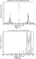
- FIG. 7 is a graph showing the spectrum of a typical double-sideband signal.
- An optical SSB filter can be used to suppress one of the sidebands.
- FIG. 8 shows the spectrum of the resulting single-sideband signal output by an SSB filter.
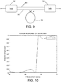
- an optical single-sideband filter 44 comprises a splitter 52 and a coupler (a.k.a. combiner) 54 which are optically coupled by means of a pair of waveguides 48 and 50.
- the waveguide 48 incorporates an asymmetric Mach-Zehnder interferometer (not shown).
- An optical ring resonator 34 is coupled to the waveguide 50 by means of a symmetric Mach-Zehnder interferometer (indicated by an X in FIG. 9 ).
- the power coupling coefficient is indicated by K in FIG. 9 .
- the free spectral range and the widths of the passband and stopband are selected such that one sideband of the modulated optical signal is passed and the other sideband is suppressed.
- the power response shows excellent rejection in the frequency range of 6 to 15 GHz.
- Multiple subsystem modules of the type depicted in FIG. 2 and implemented using optical beamforming networks of the type shown in FIG. 3 can be provided onboard a communications satellite for processing a wavelength-division multiplexed optical beam, each wavelength being processed by a unique one of the multiplicity of optical beamforming networks.
- Multiple optical beamforming networks 24 of the type depicted in FIG. 3 can be connected to the outputs of a common optical demultiplexer, which demultiplexes the wavelength-division multiplexed optical beam into respective beams of different wavelengths.
- FIG. 11 shows an optical demultiplexer 22 which is receiving an uplinked wavelength-division multiplexed composite optical signal.
- the wavelength-division multiplexed composite optical comprises eight different wavelengths ⁇ 1 , ⁇ 2 , ⁇ 3 , ⁇ 4 , ⁇ 5 , ⁇ 6 , ⁇ 7 , and ⁇ 8 .
- the optical demultiplexer 22 comprises optical splitters which separate the multiplexed wavelengths, outputting eight optical beams having respective wavelengths ⁇ 1 through ⁇ 8 to respective optical beamforming networks 24 via respective waveguides (e.g., respective optical fibers).
- Each of eight optical beamforming networks 24 receives an optical beam having one of the respective wavelengths ⁇ 1 , ⁇ 2 , ⁇ 3 , ⁇ 4 , ⁇ 5 , ⁇ 6 , ⁇ 7 , and ⁇ 8 .
- the optical beamforming networks 24 perform amplitude and time delay adjustment of those optical signals to facilitate the formation of a transmit beam by the phased-array transmit antenna (not shown in FIG. 11 ).
- FIG. 12 is a block diagram showing a module of a multi-beam antenna feed system comprising a stack of n passive optical beamforming networks 24, each individual optical beamforming network 24 being configured as seen in FIG. 3 .
- the respective phase shifts applied by each branch of the binary tree are indicated by parallelograms respectively labeled ⁇ 1 , ⁇ 2 , ..., ⁇ m -3 , ⁇ m -2 , ⁇ m -1 , ⁇ m .
- the respective attenuation weights (for amplitude adjustment) are indicated by parallelograms labeled A .
- Each of the n passive optical beamforming networks 24 receives a respective optical beam from a demultiplexer (not shown in FIG.
- Each optical beamforming network 24 processes a unique wavelength.
- Each of the m groups of component signals which are phase shifted by a respective one of the phase shifts ⁇ 1 , ⁇ 2 , ..., ⁇ m -3 , ⁇ m -2 , ⁇ m -1 , ⁇ m are combined by respective multiplexers 42 to form respective composite optical signals.
- Those m composite optical signals are converted into respective 12-GHz composite RF signals by respective photodetectors (not shown in FIG. 12 , but see FIG. 2 ), which composite RF signals are amplified by respective high-power amplifiers 28 on their way to m respective elements 30 of a transmit antenna array.
- FIG. 13 shows an optical multiplexer 42 that is receiving n beamformed component signals of different wavelengths ⁇ 1 through ⁇ n and combines them to form a wavelength-division multiplexed composite optical signal.
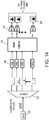
- FIG. 14 shows components of a signal processing system onboard a satellite that converts an uplinked wavelength-division multiplexed composite optical signal into RF signals for a multiplicity of spot beams to be broadcast in accordance with one embodiment.
- the system depicted in FIG. 14 comprises an optical demultiplexer 22 that receives a wavelength-division multiplexed composite optical from a lens 20 of a receiver telescope and splits the composite signal into n components having respective different wavelengths ⁇ 1 through ⁇ n .
- the component optical signals are passed through respective optical single-sideband (SSB) filters 44 and into respective binary tree-based 1 x m optical beamforming networks 24.
- SSB optical single-sideband
- Each optical beamforming network 24 processes a respective component optical signal of a unique wavelength and outputs a set of m beamformed component signals for that respective unique wavelength to respective multiplexers 42.
- Beamformed component signals having different wavelengths ⁇ 1 through ⁇ n but the same time delay are combined into respective wavelength-division multiplexed beamformed composite signals by respective optical multiplexers 42.
- These beamformed composite signals are converted to the electrical domain by respective photonic sensors 26 (e.g., photodetectors).
- the resulting RF electrical signals are amplified by respective RF power amplifiers (not shown in FIG. 14 , but see FIG. 12 ).
- the amplified RF signals are then transmitted by respective elements of the transmit antenna array (not shown in FIG.14 , but see elements 30 in FIG. 12 ).
- the disclosure comprises the following items:
Landscapes
- Engineering & Computer Science (AREA)
- Physics & Mathematics (AREA)
- Astronomy & Astrophysics (AREA)
- General Physics & Mathematics (AREA)
- Computer Networks & Wireless Communication (AREA)
- Signal Processing (AREA)
- Aviation & Aerospace Engineering (AREA)
- Electromagnetism (AREA)
- Optical Communication System (AREA)
Applications Claiming Priority (1)
| Application Number | Priority Date | Filing Date | Title |
|---|---|---|---|
| US15/078,413 US10312999B2 (en) | 2016-03-23 | 2016-03-23 | High-capacity communications satellite using passive optical beamforming |
Publications (2)
| Publication Number | Publication Date |
|---|---|
| EP3223441A1 true EP3223441A1 (fr) | 2017-09-27 |
| EP3223441B1 EP3223441B1 (fr) | 2021-03-10 |
Family
ID=58398119
Family Applications (1)
| Application Number | Title | Priority Date | Filing Date |
|---|---|---|---|
| EP17162200.4A Active EP3223441B1 (fr) | 2016-03-23 | 2017-03-21 | Satellite de communication à grande capacité utilisant une formation de faisceau optique passive |
Country Status (2)
| Country | Link |
|---|---|
| US (1) | US10312999B2 (fr) |
| EP (1) | EP3223441B1 (fr) |
Families Citing this family (21)
| Publication number | Priority date | Publication date | Assignee | Title |
|---|---|---|---|---|
| SG11201807356VA (en) | 2016-03-22 | 2018-09-27 | Lyteloop Technologies Llc | Data in motion storage system and method |
| FR3054670B1 (fr) * | 2016-07-27 | 2019-12-13 | Airbus Defence And Space | Procede et systeme d’estimation de la direction d’un satellite en phase de transfert d’une orbite initiale vers une orbite de mission |
| DE102016213764B4 (de) * | 2016-07-27 | 2018-02-22 | Deutsches Zentrum für Luft- und Raumfahrt e.V. | Verfahren zum Übertragen eines binären Datensignals über einen optischen Feeder-Link zu oder von einem Satelliten |
| US11005178B2 (en) | 2017-11-21 | 2021-05-11 | Phase Sensitive Innovations, Inc. | Antenna and antenna array configurations, antenna systems and related methods of operation |
| US10534110B2 (en) * | 2018-01-09 | 2020-01-14 | Precision Optical Transceivers Inc. | Integrated photonics device for continuous phase-controlled active beam steering and forming |
| US10523331B2 (en) | 2018-01-12 | 2019-12-31 | Precision Optical Transceivers Inc. | Increasing RF power output in photonics-fed phased array antenna systems |
| US10505632B1 (en) | 2018-07-23 | 2019-12-10 | Precision Optical Transceivers Inc. | Fiber bus extender embedment |
| US10629989B2 (en) | 2018-02-23 | 2020-04-21 | Precision Optical Transceivers Inc. | Phased array communication system with remote RF transceiver and antenna beam control |
| EP4068651B1 (fr) | 2018-03-06 | 2025-08-13 | Eutelsat SA | Procédé de démodulation adaptative et satellite mettant en oeuvre un tel procédé |
| WO2020028716A1 (fr) | 2018-08-02 | 2020-02-06 | Lyteloop Technologies, Llc | Procédé et appareil de stockage de signaux d'onde dans une cavité |
| ES2939349T3 (es) | 2018-08-10 | 2023-04-21 | Nkb Properties Man Llc | Sistema y procedimiento para ampliar la longitud de la trayectoria de una señal de onda mediante multiplexación angular |
| BR112021004133A8 (pt) | 2018-11-05 | 2023-05-09 | Lyteloop Tech Llc | Sistemas e métodos para construir, operar e controlar múltiplos amplificadores, regeneradores e transceptores usando os componentes comuns compartilhados |
| US11183770B2 (en) * | 2019-05-17 | 2021-11-23 | Raytheon Company | Dual polarization RF antenna feed module and photonic integrated circuit (PIC) |
| US10749551B1 (en) * | 2019-05-31 | 2020-08-18 | Cox Communications, Inc. | Systems and methods for extended spectrum amplifiers |
| US11368225B2 (en) * | 2019-11-18 | 2022-06-21 | General Electric Company | Satellite relay communication systems |
| JP7323826B2 (ja) * | 2019-11-25 | 2023-08-09 | 日本電信電話株式会社 | 無線送信システム、無線受信システム、基地局装置、及び無線通信システム、並びに無線送信方法、及び無線受信方法 |
| US11105980B1 (en) * | 2020-04-07 | 2021-08-31 | Globalfoundries U.S. Inc. | Demultiplexer and related method to process multiplexed optical inputs |
| US11747376B2 (en) * | 2021-04-01 | 2023-09-05 | City University Of Hong Kong | Photonic device and a terahertz signal generator |
| US20220397596A1 (en) * | 2021-06-15 | 2022-12-15 | Nucrypt, LLC | System and method for multiplexing and demultiplexing rf signals using a plurality of rf-to-optical antennas |
| US12189180B2 (en) * | 2022-06-14 | 2025-01-07 | Raytheon Company | Photonic integrated circuit multi-wavelength phase modulator networks |
| CN117896007A (zh) * | 2022-10-09 | 2024-04-16 | 宁波环球广电科技有限公司 | 集成阵列天线的硅光晶片 |
Citations (3)
| Publication number | Priority date | Publication date | Assignee | Title |
|---|---|---|---|---|
| WO1998002765A1 (fr) * | 1996-07-15 | 1998-01-22 | Mcdonnell Douglas Corporation | Reseau de temporisation optique adressable en longueur d'onde, et antenne reseau a elements en phase pourvue d'un tel reseau |
| EP0871343A2 (fr) * | 1997-04-09 | 1998-10-14 | TRW Inc. | Commutateur optique sans séparateurs avec capacité de diffusion |
| US7084811B1 (en) * | 2004-09-14 | 2006-08-01 | Hrl Laboratories, Llc | Agile optical wavelength selection for antenna beamforming |
Family Cites Families (12)
| Publication number | Priority date | Publication date | Assignee | Title |
|---|---|---|---|---|
| US5424862A (en) | 1994-04-28 | 1995-06-13 | Glynn; Thomas W. | High capacity communications satellite |
| US5659413A (en) | 1995-02-28 | 1997-08-19 | The Mitre Corporation | Laser satellite communication system |
| US6452546B1 (en) * | 2000-06-14 | 2002-09-17 | Hrl Laboratories, Llc | Wavelength division multiplexing methods and apparatus for constructing photonic beamforming networks |
| US6807343B2 (en) * | 2001-05-29 | 2004-10-19 | The United States Of America As Represented By The Secretary Of The Navy | Reconfigurable optical beamformer for simplified time steered arrays |
| US7929864B2 (en) * | 2006-03-02 | 2011-04-19 | Alcatel-Lucent Usa Inc. | Optical beamforming transmitter |
| AU2011223493B2 (en) | 2010-03-02 | 2015-02-05 | The University Of Sydney | Phase shifter and photonic controlled beam former for phased array antennas |
| US9397397B2 (en) | 2011-10-03 | 2016-07-19 | Universiteit Twente | Electronically-steered Ku-band phased array antenna comprising an integrated photonic beamformer |
| US9444502B2 (en) | 2012-05-21 | 2016-09-13 | L-3 Communications Corporation | Interference cancellation system for cancelling interference in the optical domain |
| US9838125B2 (en) * | 2014-08-26 | 2017-12-05 | The Trustees Of Princeton University | Multibeam radio frequency photonic beamformer using a multi-signal slow light time delay unit |
| US9941967B2 (en) * | 2015-03-11 | 2018-04-10 | The Aerospace Corporation | Satellite laser communications relay network |
| US10224628B2 (en) * | 2015-04-20 | 2019-03-05 | Instituto De Telecommunicações | Photonic beamforming system for a phased array antenna receiver |
| US10103812B2 (en) * | 2016-01-27 | 2018-10-16 | The Boeing Company | Satellite communication system |
-
2016
- 2016-03-23 US US15/078,413 patent/US10312999B2/en active Active
-
2017
- 2017-03-21 EP EP17162200.4A patent/EP3223441B1/fr active Active
Patent Citations (3)
| Publication number | Priority date | Publication date | Assignee | Title |
|---|---|---|---|---|
| WO1998002765A1 (fr) * | 1996-07-15 | 1998-01-22 | Mcdonnell Douglas Corporation | Reseau de temporisation optique adressable en longueur d'onde, et antenne reseau a elements en phase pourvue d'un tel reseau |
| EP0871343A2 (fr) * | 1997-04-09 | 1998-10-14 | TRW Inc. | Commutateur optique sans séparateurs avec capacité de diffusion |
| US7084811B1 (en) * | 2004-09-14 | 2006-08-01 | Hrl Laboratories, Llc | Agile optical wavelength selection for antenna beamforming |
Also Published As
| Publication number | Publication date |
|---|---|
| EP3223441B1 (fr) | 2021-03-10 |
| US20190068282A1 (en) | 2019-02-28 |
| US10312999B2 (en) | 2019-06-04 |
Similar Documents
| Publication | Publication Date | Title |
|---|---|---|
| EP3223441B1 (fr) | Satellite de communication à grande capacité utilisant une formation de faisceau optique passive | |
| US6912075B1 (en) | Ring architecture for an optical satellite communication network with passive optical routing | |
| US9768909B2 (en) | Systems and techniques for orbital angular momentum based reconfigurable switching | |
| US11051089B1 (en) | Microwave photonics enabled beam-forming and channelization | |
| US9917651B2 (en) | Feed signal generation for a phased array antenna | |
| EP2723001B1 (fr) | Système de télécommunications par satellite à grande capacité à couverture multifaisceaux et à réutilisation de fréquence | |
| US8400355B1 (en) | Passive photonic dense wavelength-division multiplexing true-time-delay system | |
| JPH07202815A (ja) | 光学・rf信号用光学デマルチプレクサ | |
| EP3183772B1 (fr) | Un transceiver pour un reseau d'antennes à commande de phase | |
| US20130177319A1 (en) | Phased antenna array with electro-optic readout circuit with mll and related methods | |
| US20130202308A1 (en) | Phased antenna array including a plurality of electro-optical circuits having an optical source with an opto-electronic oscillator and associated methods | |
| US9397397B2 (en) | Electronically-steered Ku-band phased array antenna comprising an integrated photonic beamformer | |
| JP2001085925A (ja) | 無線通信システム | |
| US20110091217A1 (en) | Apparatus and method for transporting multiple radio signals over optical fiber | |
| EP3382797B1 (fr) | Antenne réseau à commande de phase | |
| US20130202306A1 (en) | Phased antenna array including a plurality of electro-optical circuits with an electro-optical modulator and associated methods | |
| CN117040575A (zh) | 一种多波长调制的相干光学接收多波束形成装置及方法 | |
| US20130177315A1 (en) | Phased antenna array with electro-optic readout circuit with multiplexing and mll and related methods | |
| Graceffo et al. | Hybrid rf & fso for defense and 5g backhaul | |
| EP3751758B1 (fr) | Commutation lambda photonique pour satellites | |
| US7209079B2 (en) | Beam steering apparatus | |
| CN113541809A (zh) | 一种多波段可调光生毫米波产生系统 | |
| US20130202307A1 (en) | Phased antenna array including a plurality of electro-optical circuits spaced apart from and coupled to a plurality of antenna circuits and associated methods | |
| US7302185B2 (en) | Device and method for millimeter wave detection and block conversion | |
| EP3269053B1 (fr) | Récepteur pour antenne réseau à commande de phase |
Legal Events
| Date | Code | Title | Description |
|---|---|---|---|
| PUAI | Public reference made under article 153(3) epc to a published international application that has entered the european phase |
Free format text: ORIGINAL CODE: 0009012 |
|
| STAA | Information on the status of an ep patent application or granted ep patent |
Free format text: STATUS: REQUEST FOR EXAMINATION WAS MADE |
|
| 17P | Request for examination filed |
Effective date: 20170321 |
|
| AK | Designated contracting states |
Kind code of ref document: A1 Designated state(s): AL AT BE BG CH CY CZ DE DK EE ES FI FR GB GR HR HU IE IS IT LI LT LU LV MC MK MT NL NO PL PT RO RS SE SI SK SM TR |
|
| AX | Request for extension of the european patent |
Extension state: BA ME |
|
| STAA | Information on the status of an ep patent application or granted ep patent |
Free format text: STATUS: EXAMINATION IS IN PROGRESS |
|
| 17Q | First examination report despatched |
Effective date: 20190806 |
|
| GRAP | Despatch of communication of intention to grant a patent |
Free format text: ORIGINAL CODE: EPIDOSNIGR1 |
|
| STAA | Information on the status of an ep patent application or granted ep patent |
Free format text: STATUS: GRANT OF PATENT IS INTENDED |
|
| RIC1 | Information provided on ipc code assigned before grant |
Ipc: H04B 10/118 20130101ALI20200911BHEP Ipc: H04B 10/00 20130101ALN20200911BHEP Ipc: H01Q 3/26 20060101ALI20200911BHEP Ipc: H04B 7/185 20060101AFI20200911BHEP Ipc: H01Q 3/00 20060101ALN20200911BHEP |
|
| RIC1 | Information provided on ipc code assigned before grant |
Ipc: H04B 10/00 20130101ALN20200923BHEP Ipc: H01Q 3/00 20060101ALN20200923BHEP Ipc: H04B 10/118 20130101ALI20200923BHEP Ipc: H01Q 3/26 20060101ALI20200923BHEP Ipc: H04B 7/185 20060101AFI20200923BHEP |
|
| INTG | Intention to grant announced |
Effective date: 20201016 |
|
| GRAS | Grant fee paid |
Free format text: ORIGINAL CODE: EPIDOSNIGR3 |
|
| GRAA | (expected) grant |
Free format text: ORIGINAL CODE: 0009210 |
|
| STAA | Information on the status of an ep patent application or granted ep patent |
Free format text: STATUS: THE PATENT HAS BEEN GRANTED |
|
| AK | Designated contracting states |
Kind code of ref document: B1 Designated state(s): AL AT BE BG CH CY CZ DE DK EE ES FI FR GB GR HR HU IE IS IT LI LT LU LV MC MK MT NL NO PL PT RO RS SE SI SK SM TR |
|
| REG | Reference to a national code |
Ref country code: GB Ref legal event code: FG4D |
|
| REG | Reference to a national code |
Ref country code: AT Ref legal event code: REF Ref document number: 1370987 Country of ref document: AT Kind code of ref document: T Effective date: 20210315 Ref country code: CH Ref legal event code: EP |
|
| REG | Reference to a national code |
Ref country code: IE Ref legal event code: FG4D |
|
| REG | Reference to a national code |
Ref country code: DE Ref legal event code: R096 Ref document number: 602017034149 Country of ref document: DE |
|
| REG | Reference to a national code |
Ref country code: LT Ref legal event code: MG9D |
|
| PG25 | Lapsed in a contracting state [announced via postgrant information from national office to epo] |
Ref country code: NO Free format text: LAPSE BECAUSE OF FAILURE TO SUBMIT A TRANSLATION OF THE DESCRIPTION OR TO PAY THE FEE WITHIN THE PRESCRIBED TIME-LIMIT Effective date: 20210610 Ref country code: HR Free format text: LAPSE BECAUSE OF FAILURE TO SUBMIT A TRANSLATION OF THE DESCRIPTION OR TO PAY THE FEE WITHIN THE PRESCRIBED TIME-LIMIT Effective date: 20210310 Ref country code: FI Free format text: LAPSE BECAUSE OF FAILURE TO SUBMIT A TRANSLATION OF THE DESCRIPTION OR TO PAY THE FEE WITHIN THE PRESCRIBED TIME-LIMIT Effective date: 20210310 Ref country code: GR Free format text: LAPSE BECAUSE OF FAILURE TO SUBMIT A TRANSLATION OF THE DESCRIPTION OR TO PAY THE FEE WITHIN THE PRESCRIBED TIME-LIMIT Effective date: 20210611 Ref country code: BG Free format text: LAPSE BECAUSE OF FAILURE TO SUBMIT A TRANSLATION OF THE DESCRIPTION OR TO PAY THE FEE WITHIN THE PRESCRIBED TIME-LIMIT Effective date: 20210610 Ref country code: LT Free format text: LAPSE BECAUSE OF FAILURE TO SUBMIT A TRANSLATION OF THE DESCRIPTION OR TO PAY THE FEE WITHIN THE PRESCRIBED TIME-LIMIT Effective date: 20210310 |
|
| REG | Reference to a national code |
Ref country code: AT Ref legal event code: MK05 Ref document number: 1370987 Country of ref document: AT Kind code of ref document: T Effective date: 20210310 |
|
| REG | Reference to a national code |
Ref country code: NL Ref legal event code: MP Effective date: 20210310 |
|
| PG25 | Lapsed in a contracting state [announced via postgrant information from national office to epo] |
Ref country code: SE Free format text: LAPSE BECAUSE OF FAILURE TO SUBMIT A TRANSLATION OF THE DESCRIPTION OR TO PAY THE FEE WITHIN THE PRESCRIBED TIME-LIMIT Effective date: 20210310 Ref country code: RS Free format text: LAPSE BECAUSE OF FAILURE TO SUBMIT A TRANSLATION OF THE DESCRIPTION OR TO PAY THE FEE WITHIN THE PRESCRIBED TIME-LIMIT Effective date: 20210310 Ref country code: LV Free format text: LAPSE BECAUSE OF FAILURE TO SUBMIT A TRANSLATION OF THE DESCRIPTION OR TO PAY THE FEE WITHIN THE PRESCRIBED TIME-LIMIT Effective date: 20210310 |
|
| PG25 | Lapsed in a contracting state [announced via postgrant information from national office to epo] |
Ref country code: NL Free format text: LAPSE BECAUSE OF FAILURE TO SUBMIT A TRANSLATION OF THE DESCRIPTION OR TO PAY THE FEE WITHIN THE PRESCRIBED TIME-LIMIT Effective date: 20210310 |
|
| PG25 | Lapsed in a contracting state [announced via postgrant information from national office to epo] |
Ref country code: CZ Free format text: LAPSE BECAUSE OF FAILURE TO SUBMIT A TRANSLATION OF THE DESCRIPTION OR TO PAY THE FEE WITHIN THE PRESCRIBED TIME-LIMIT Effective date: 20210310 Ref country code: EE Free format text: LAPSE BECAUSE OF FAILURE TO SUBMIT A TRANSLATION OF THE DESCRIPTION OR TO PAY THE FEE WITHIN THE PRESCRIBED TIME-LIMIT Effective date: 20210310 Ref country code: AT Free format text: LAPSE BECAUSE OF FAILURE TO SUBMIT A TRANSLATION OF THE DESCRIPTION OR TO PAY THE FEE WITHIN THE PRESCRIBED TIME-LIMIT Effective date: 20210310 Ref country code: SM Free format text: LAPSE BECAUSE OF FAILURE TO SUBMIT A TRANSLATION OF THE DESCRIPTION OR TO PAY THE FEE WITHIN THE PRESCRIBED TIME-LIMIT Effective date: 20210310 |
|
| REG | Reference to a national code |
Ref country code: CH Ref legal event code: PL |
|
| PG25 | Lapsed in a contracting state [announced via postgrant information from national office to epo] |
Ref country code: IS Free format text: LAPSE BECAUSE OF FAILURE TO SUBMIT A TRANSLATION OF THE DESCRIPTION OR TO PAY THE FEE WITHIN THE PRESCRIBED TIME-LIMIT Effective date: 20210710 Ref country code: PL Free format text: LAPSE BECAUSE OF FAILURE TO SUBMIT A TRANSLATION OF THE DESCRIPTION OR TO PAY THE FEE WITHIN THE PRESCRIBED TIME-LIMIT Effective date: 20210310 Ref country code: PT Free format text: LAPSE BECAUSE OF FAILURE TO SUBMIT A TRANSLATION OF THE DESCRIPTION OR TO PAY THE FEE WITHIN THE PRESCRIBED TIME-LIMIT Effective date: 20210712 Ref country code: RO Free format text: LAPSE BECAUSE OF FAILURE TO SUBMIT A TRANSLATION OF THE DESCRIPTION OR TO PAY THE FEE WITHIN THE PRESCRIBED TIME-LIMIT Effective date: 20210310 Ref country code: SK Free format text: LAPSE BECAUSE OF FAILURE TO SUBMIT A TRANSLATION OF THE DESCRIPTION OR TO PAY THE FEE WITHIN THE PRESCRIBED TIME-LIMIT Effective date: 20210310 |
|
| REG | Reference to a national code |
Ref country code: DE Ref legal event code: R097 Ref document number: 602017034149 Country of ref document: DE |
|
| REG | Reference to a national code |
Ref country code: BE Ref legal event code: MM Effective date: 20210331 |
|
| PLBE | No opposition filed within time limit |
Free format text: ORIGINAL CODE: 0009261 |
|
| STAA | Information on the status of an ep patent application or granted ep patent |
Free format text: STATUS: NO OPPOSITION FILED WITHIN TIME LIMIT |
|
| PG25 | Lapsed in a contracting state [announced via postgrant information from national office to epo] |
Ref country code: LI Free format text: LAPSE BECAUSE OF NON-PAYMENT OF DUE FEES Effective date: 20210331 Ref country code: LU Free format text: LAPSE BECAUSE OF NON-PAYMENT OF DUE FEES Effective date: 20210321 Ref country code: MC Free format text: LAPSE BECAUSE OF FAILURE TO SUBMIT A TRANSLATION OF THE DESCRIPTION OR TO PAY THE FEE WITHIN THE PRESCRIBED TIME-LIMIT Effective date: 20210310 Ref country code: AL Free format text: LAPSE BECAUSE OF FAILURE TO SUBMIT A TRANSLATION OF THE DESCRIPTION OR TO PAY THE FEE WITHIN THE PRESCRIBED TIME-LIMIT Effective date: 20210310 Ref country code: CH Free format text: LAPSE BECAUSE OF NON-PAYMENT OF DUE FEES Effective date: 20210331 Ref country code: DK Free format text: LAPSE BECAUSE OF FAILURE TO SUBMIT A TRANSLATION OF THE DESCRIPTION OR TO PAY THE FEE WITHIN THE PRESCRIBED TIME-LIMIT Effective date: 20210310 Ref country code: ES Free format text: LAPSE BECAUSE OF FAILURE TO SUBMIT A TRANSLATION OF THE DESCRIPTION OR TO PAY THE FEE WITHIN THE PRESCRIBED TIME-LIMIT Effective date: 20210310 Ref country code: IE Free format text: LAPSE BECAUSE OF NON-PAYMENT OF DUE FEES Effective date: 20210321 |
|
| 26N | No opposition filed |
Effective date: 20211213 |
|
| PG25 | Lapsed in a contracting state [announced via postgrant information from national office to epo] |
Ref country code: SI Free format text: LAPSE BECAUSE OF FAILURE TO SUBMIT A TRANSLATION OF THE DESCRIPTION OR TO PAY THE FEE WITHIN THE PRESCRIBED TIME-LIMIT Effective date: 20210310 |
|
| PG25 | Lapsed in a contracting state [announced via postgrant information from national office to epo] |
Ref country code: IT Free format text: LAPSE BECAUSE OF FAILURE TO SUBMIT A TRANSLATION OF THE DESCRIPTION OR TO PAY THE FEE WITHIN THE PRESCRIBED TIME-LIMIT Effective date: 20210310 |
|
| PG25 | Lapsed in a contracting state [announced via postgrant information from national office to epo] |
Ref country code: IS Free format text: LAPSE BECAUSE OF FAILURE TO SUBMIT A TRANSLATION OF THE DESCRIPTION OR TO PAY THE FEE WITHIN THE PRESCRIBED TIME-LIMIT Effective date: 20210710 |
|
| PG25 | Lapsed in a contracting state [announced via postgrant information from national office to epo] |
Ref country code: BE Free format text: LAPSE BECAUSE OF NON-PAYMENT OF DUE FEES Effective date: 20210331 |
|
| PG25 | Lapsed in a contracting state [announced via postgrant information from national office to epo] |
Ref country code: HU Free format text: LAPSE BECAUSE OF FAILURE TO SUBMIT A TRANSLATION OF THE DESCRIPTION OR TO PAY THE FEE WITHIN THE PRESCRIBED TIME-LIMIT; INVALID AB INITIO Effective date: 20170321 |
|
| P01 | Opt-out of the competence of the unified patent court (upc) registered |
Effective date: 20230516 |
|
| PG25 | Lapsed in a contracting state [announced via postgrant information from national office to epo] |
Ref country code: CY Free format text: LAPSE BECAUSE OF FAILURE TO SUBMIT A TRANSLATION OF THE DESCRIPTION OR TO PAY THE FEE WITHIN THE PRESCRIBED TIME-LIMIT Effective date: 20210310 |
|
| PG25 | Lapsed in a contracting state [announced via postgrant information from national office to epo] |
Ref country code: MK Free format text: LAPSE BECAUSE OF FAILURE TO SUBMIT A TRANSLATION OF THE DESCRIPTION OR TO PAY THE FEE WITHIN THE PRESCRIBED TIME-LIMIT Effective date: 20210310 |
|
| PG25 | Lapsed in a contracting state [announced via postgrant information from national office to epo] |
Ref country code: MT Free format text: LAPSE BECAUSE OF FAILURE TO SUBMIT A TRANSLATION OF THE DESCRIPTION OR TO PAY THE FEE WITHIN THE PRESCRIBED TIME-LIMIT Effective date: 20210310 |
|
| PG25 | Lapsed in a contracting state [announced via postgrant information from national office to epo] |
Ref country code: TR Free format text: LAPSE BECAUSE OF FAILURE TO SUBMIT A TRANSLATION OF THE DESCRIPTION OR TO PAY THE FEE WITHIN THE PRESCRIBED TIME-LIMIT Effective date: 20210310 |
|
| PGFP | Annual fee paid to national office [announced via postgrant information from national office to epo] |
Ref country code: GB Payment date: 20260327 Year of fee payment: 10 |
|
| PGFP | Annual fee paid to national office [announced via postgrant information from national office to epo] |
Ref country code: DE Payment date: 20260327 Year of fee payment: 10 |
|
| PGFP | Annual fee paid to national office [announced via postgrant information from national office to epo] |
Ref country code: FR Payment date: 20260325 Year of fee payment: 10 |