EP3223982B1 - Mandrin de serrage - Google Patents
Mandrin de serrage Download PDFInfo
- Publication number
- EP3223982B1 EP3223982B1 EP15816374.1A EP15816374A EP3223982B1 EP 3223982 B1 EP3223982 B1 EP 3223982B1 EP 15816374 A EP15816374 A EP 15816374A EP 3223982 B1 EP3223982 B1 EP 3223982B1
- Authority
- EP
- European Patent Office
- Prior art keywords
- sleeve
- bolt
- tool
- recess
- wall
- Prior art date
- Legal status (The legal status is an assumption and is not a legal conclusion. Google has not performed a legal analysis and makes no representation as to the accuracy of the status listed.)
- Active
Links
Images
Classifications
-
- B—PERFORMING OPERATIONS; TRANSPORTING
- B23—MACHINE TOOLS; METAL-WORKING NOT OTHERWISE PROVIDED FOR
- B23B—TURNING; BORING
- B23B31/00—Chucks; Expansion mandrels; Adaptations thereof for remote control
- B23B31/02—Chucks
- B23B31/24—Chucks characterised by features relating primarily to remote control of the gripping means
- B23B31/30—Chucks characterised by features relating primarily to remote control of the gripping means using fluid-pressure means in the chuck
- B23B31/305—Chucks characterised by features relating primarily to remote control of the gripping means using fluid-pressure means in the chuck the gripping means is a deformable sleeve
-
- B—PERFORMING OPERATIONS; TRANSPORTING
- B23—MACHINE TOOLS; METAL-WORKING NOT OTHERWISE PROVIDED FOR
- B23B—TURNING; BORING
- B23B31/00—Chucks; Expansion mandrels; Adaptations thereof for remote control
- B23B31/02—Chucks
- B23B31/10—Chucks characterised by the retaining or gripping devices or their immediate operating means
- B23B31/107—Retention by laterally-acting detents, e.g. pins, screws, wedges; Retention by loose elements, e.g. balls
-
- B—PERFORMING OPERATIONS; TRANSPORTING
- B23—MACHINE TOOLS; METAL-WORKING NOT OTHERWISE PROVIDED FOR
- B23B—TURNING; BORING
- B23B31/00—Chucks; Expansion mandrels; Adaptations thereof for remote control
- B23B31/005—Cylindrical shanks of tools
-
- B—PERFORMING OPERATIONS; TRANSPORTING
- B23—MACHINE TOOLS; METAL-WORKING NOT OTHERWISE PROVIDED FOR
- B23B—TURNING; BORING
- B23B31/00—Chucks; Expansion mandrels; Adaptations thereof for remote control
- B23B31/02—Chucks
- B23B31/028—Chucks the axial positioning of the tool being adjustable
-
- B—PERFORMING OPERATIONS; TRANSPORTING
- B23—MACHINE TOOLS; METAL-WORKING NOT OTHERWISE PROVIDED FOR
- B23B—TURNING; BORING
- B23B2270/00—Details of turning, boring or drilling machines, processes or tools not otherwise provided for
- B23B2270/06—Use of elastic deformation
Definitions
- the invention relates to a chuck according to the preamble of claim 1.
- a chuck is from the document WO2004 / 056279A2 known.
- Chucks of the type mentioned here are known. They have a coupling section and a receiving section, via which the chuck can be acted upon with a machine tool directly or via an intermediate piece or an adapter or the like, in order to set a tool received by it in rotation.
- the receiving section is provided with a recess into which a sleeve can be inserted, which receives the tool. It is provided with a securing device, with the aid of which the tool is axially fixed within the sleeve.
- axial securing of a tool within the sleeve is of crucial importance in many areas of application because, for example, the tool can be pulled out of the sleeve, and thus out of the receiving section of a chuck, during a milling process with a high feed rate.
- Known securing devices have, for example, at least one pin, which preferably penetrates the wall of the sleeve in a plane on which the longitudinal axis of the sleeve is perpendicular. The pin penetrating the sleeve engages with the tool inserted into the sleeve, for example into a transverse groove, that is to say into a groove running perpendicular to the longitudinal extension of the tool.
- the object of the invention is therefore to provide a chuck which avoids this disadvantage.
- a chuck of the type mentioned above which has the features mentioned in claim 1.
- This chuck has a coupling section, via which it can be connected to a machine tool either directly or via an adapter, an intermediate piece or the like, and also a receiving section.
- This has a recess into which a sleeve provided with a wall can be inserted, into which a tool can be inserted.
- the sleeve has a securing device for axially fixing the tool within the sleeve.
- the chuck is characterized in that the securing device has a bolt which is mounted in a recess in the wall of the sleeve and is movable at an acute angle, preferably essentially in the vertical direction, to the longitudinal extent of the sleeve.
- the length of the bolt measured perpendicular to the longitudinal extent of the sleeve is greater than the thickness of the wall of the sleeve.
- the bolt When the sleeve is clamped with the tool within the receiving section, the bolt is pressed into the interior of the sleeve and into a recess provided in the side wall of the tool, so that the tool is secured axially in the sleeve and thus in the chuck.
- a preferred embodiment of the chuck is characterized in that the bolt is held by a holding arm, which is preferably designed as a spring bar and connects the bolt to the sleeve.
- This configuration of the chuck is characterized by a very simple structure and is very reliable.
- An embodiment is particularly preferred which is characterized in that the spring bar extends from the edge of the recess receiving the bolt and is connected to the bolt.
- This type of resilient mounting of the bolt is characterized by an extremely small space requirement, so that no changes need to be made either to the receiving section or to the tool to be accommodated in order to adapt to the resilient mounting.
- a particularly preferred embodiment is characterized in that the spring bar is an integral part of the wall and / or the bolt, so that fastening means for attaching the spring bar to the wall and / or the bolt can be dispensed with.
- the sleeve has a prestressing element which has a tool inserted into the sleeve with a Axial force or biasing force is applied so that it is arranged in a precisely predetermined axial position in the receiving section of the chuck during the clamping of the sleeve.
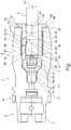
- the chuck 1 shown in the figure has a coupling section 3, which serves to connect the chuck 1 in a known manner to a machine tool, either directly or via an adapter, an intermediate piece or the like, in order to introduce a torque into the chuck 1 to be able to rotate a tool inserted into the chuck 1.
- the tool can be a drill, milling cutter, grinding tool or the like.
- the coupling section 3 has a known hollow shaft 7, via which the chuck 1 can be held securely in the machine tool or an adapter, intermediate piece or the like.
- the chuck 1 also has a receiving section 9 which is provided with a recess 11 which opens toward the free end 13 of the receiving section 9.
- the exemplary embodiment shown here is preferably provided with a central part 15, which comprises, for example, a gripper groove 17 into which a gripping tool for handling the chuck 1 can engage, for example in order to automatically remove it from a machine tool or insert it into it.
- a sleeve 19 is inserted into the recess 11 of the chuck 1, the outer diameter of which is adapted to the inner diameter of the recess 11 such that the sleeve 19 can be securely fixed in the recess 11 of the receiving section 9.
- the receiving section 9 has a hydraulic expansion chuck 21, with the aid of which the sleeve 19 and thus the tool 5 inserted into it can be held securely.
- Hydraulic chucks of the type mentioned here are known. They have a thin-walled wall section 22, which is at least in some areas part of the inner wall 23 of the recess 11.
- a cavity 27 is provided which is filled with a hydraulic fluid which can be acted upon by an overpressure in a suitable and known manner.
- an overpressure is built up in the cavity 27 and thus the elastic wall section 22 pushes into the interior of the recess 11 and thus against the outer wall of the sleeve 19. In this way, the sleeve 19 is held firmly in the receiving section 9.
- the sleeve 19 has a base body 29 which has a wall 33 which laterally surrounds a cavity 31, the outside diameter of which is smaller than the inside diameter of the recess 11 and the inside diameter of which is slightly larger in the region of the cavity 31 than that of the tool 5, which is preferably provided with a shaft 35 is provided, which is arranged inside the sleeve 19 or in the cavity 31.
- a recess 39 is made in the peripheral surface 37 of the shaft 35, which has at least on the end 41 of the shaft 37 lying in the interior of the sleeve 19 an oblique boundary surface which starts from a bottom 43 of the recess 39.
- an oblique boundary surface 45 can also be provided, the two boundary surfaces 41 and 45 enclosing an angle that opens outwards as seen from a longitudinal axis 47 of the chuck 1.
- the chuck 1 has a securing device 49 which serves to fix a tool inserted into the cavity 31 of the sleeve 19 in such a way that it cannot be displaced in the axial direction, that is to say in the direction of the central axis 47.
- the securing device 49 of the exemplary embodiment of a chuck 1 shown here has a bolt 51 which can be displaced at an acute angle, preferably perpendicular to the longitudinal extension of the sleeve 19, the length of which in the radial direction to the central axis 47 is greater than the thickness of the wall which is also measured in this direction 33 of the sleeve 19.
- the chuck 1 is shown so that the sleeve 19 in the recess 11 is firmly clamped, here by the hydraulic expansion chuck 21.
- the elastic wall section 22 of the hydraulic expansion chuck 21 therefore lies firmly on the outside on the peripheral surface 53 of the sleeve 19 and also on the outside 55 of the bolt 51.
- the recess 39 in the shaft 35 of the tool 1, viewed in the direction of the central axis 47, is arranged such that the inner surface 59 of the bolt 51 in this functional position of the chuck 1, that is to say in particular when the hydraulic expansion chuck 21 is activated, preferably at a distance within the recess 39 to the bottom 43 is arranged.
- the bolt 51 has a chamfer 61 facing the oblique boundary surface 41 of the recess 39, which forms a wedge gear together with the oblique boundary surface 41. If the bolt 51 is thus pushed into the recess 39, the tool 1 is subjected to a force which acts in the direction of the central axis 47 in the figure shown here and pulls the tool 5 into the cavity 31 of the sleeve 19.
- the sleeve 19 comprises a prestressing element 63, which acts on the tool 5 inserted into the cavity 31 with a force directed to the right, that is to say acting in the direction of the free end 13 of the receiving section 9. This force causes the tool 5 to bear precisely against the bolt 51 and is thus fixed in the chuck 1 in a precisely predetermined axial starting position.
- the sleeve 19 is provided with a collar 65 which rests on the end face 66 of the chuck 1 provided at the end 13 when the sleeve 19 is in the Recess 11 is inserted. Due to the exactly predetermined starting position of the sleeve 19 in the receiving section 9 and by ensuring the axial position of the tool 5 inside the sleeve 19 by means of the biasing element 63 and the securing device 49, the axial starting position of the tool 5 in the chuck 1 can be exactly can be set.
- the schematic diagram of the chuck 1 shown in the figure shows that the securing device 49 comprises the bolt 51.
- this is held by a holding arm 67 in a recess 69 in the wall 33 of the sleeve 19 at the desired position shown here.
- the holding arm 67 is preferably designed as a spring bar, so that the bolt 51 is held at a desired position in the recess 69.
- the bolt 51 is positioned such that its outside 55 is flush with the peripheral surface 53 of the sleeve 19.
- the outside 55 of the bolt 51 can be ground cylindrically, that is, after the insertion of the sleeve 19, it lies against the inside surface 59 of the cavity 31 over the entire surface.
- the bolt 51 can spring outwards due to the inherent elasticity of the holding arm 67. If the tool 5 is pushed deeply enough into the cavity 31 of the sleeve 19, the bolt 51 is displaced, preferably in a resilient manner, into the recess 39 made in the peripheral surface 37 of the shaft 35 of the tool 5. This allows a user to see that the tool 5 is inserted deep enough into the cavity 31 and rotated so that the bolt 51 can enter the recess 39. If the tool 5 and the sleeve 19 are inserted into the receiving section 9 in the relative position given at this moment, this is possible without any problems because the outside 55 of the bolt 51 does not strike the end face 66.
- the preferably resilient design of the holding arm 67 is therefore advantageous for the insertion of a tool 5 into the sleeve 19, because the desired positioning of the tool 5 within the cavity 31 can be recognized by the deflection of the bolt 51.
- the holding arm 67 is a separate element and to attach it on the one hand to the bolt 51 and on the other hand to the wall 33 of the sleeve 19 in a suitable manner, be it by soldering, welding, laser welding or the like.
- the holding arm 67 which is preferably designed as a spring bar, is very particularly preferably designed as an integral part of the wall 33 and / or the bolt 51.
- the bolt 51 is an integral part of the wall 33, which is indicated here by way of example in the figure by the common hatching of the sleeve 19, the holding arm 67 and the bolt 51.
- the bolt 51 measured in the direction of the central axis 47, is longer than the thickness of the wall 33, it may be advantageous to manufacture the wall 33 and the holding arm 67 acting as a spring bar in one piece, for example by laser machining a sleeve 19 or wire erosion, and then to attach the bolt 51 to the free end of the holding arm 67.
- the bolt 51 springs into the depression 39, so that the sleeve 19 can now easily be inserted into the Cavity 31 can be inserted until it assumes its desired axial position by abutment of the collar 65 on the end face 66 of the receiving section 9.
- the recess 39 has a greater extent than the width of the bolt 51
- Tool 5 is pushed by the biasing element 63 after inserting the sleeve 19 with the oblique boundary surface 41 against the chamfer 61 of the bolt 51 and thus assumes a desired axial position within the sleeve 19.
- the sleeve 19 can now be fixed in the receiving section 9 or in the recess 11 thereof by activating the hydraulic expansion chuck 21. As a result, the tool 5 is then on the chuck 1 fixed.
- the securing device 49 which in the exemplary embodiment shown here has a bolt 51 held by a holding arm 67, which is preferably designed as a spring arm, the following results:
- the holding arm 67 connected to the bolt 51 can be dispensed with. It is crucial for the functioning of the securing device 49 that the bolt 51 in the wall 33 of the sleeve 19 can be displaced at an acute angle, preferably perpendicular to the longitudinal extension of the sleeve 19, and has a length that is greater than the thickness of the wall 33
- the displaceability can also be ensured if the bolt 51 is displaceably housed in a suitable recess, not shown in the figure, for example a bore.
- the bolt 51 it is then possible for the bolt 51 to be displaced outwards when a tool 5 is introduced into the recess 11 of the receiving section 9, that is to say to move away from the central axis 47. If the tool 5 is correctly aligned, as was explained above, the bolt 51 can be moved into the recess 39 made in the tool 5 or its shaft 35 after the tool 5 has been completely inserted into the recess 11. In this position, as in the exemplary embodiment explained above, it is then held in place, for example by the elastic wall section 22, when the hydraulic expansion chuck 21 is activated.
- the bolt 51 can be held in the associated recess or bore in a simple, known manner, for example by an O-ring which is pushed onto the outer surface of the bolt 51.
- the O-ring can also be accommodated in a groove made in the outer surface, or else in a groove which is made in the inner surface of the recess or bore receiving the bolt 51.
- the sleeve 19 can preferably have one or more longitudinal slots, not shown here, in the wall 33. As a result, it can be compressed during clamping, for example when the hydraulic expansion chuck 21 is activated, so that the tool 5 is thereby also fixedly fixed in the receiving section 9.
- the sleeve 19 described here can be used as an adapter sleeve. In this case, it is necessary, for example, to provide sleeves with different inner diameters of the cavity 31 in order to be able to introduce different tool sizes. It is also conceivable to provide different sleeves 19 with bolts 51 arranged at different positions, in order to enable adaptation to different tools 5 with differently positioned recesses 39.
- the chuck 1 can be equipped with a predetermined configuration of the receiving section 9 or the associated recess 11 with different sleeves 19 in order to be able to hold different tools and to be able to fix them in the desired axial position.
Landscapes
- Engineering & Computer Science (AREA)
- Mechanical Engineering (AREA)
- Gripping On Spindles (AREA)
Claims (6)
- Mandrin de serrage (1) avec- une section de couplage (3),- une section de réception (9) présentant un évidement (11),- un manchon (19) présentant une paroi (33), insérable dans l'évidement (11) de la section de réception (9), servant recevoir un outil (5) et avec- un dispositif de sécurité (49) pour la fixation axiale d'un outil (5) à l'intérieur du manchon (19),- le dispositif de sécurité (49) présentant un boulon (51) qui est déplacé dans un évidement (69) dans la paroi (33) du manchon (19) et qui est mobile sous un angle aigu, de préférence essentiellement dans le sens vertical par rapport à l'extension longitudinale du manchon (19) et- la longueur du boulon (51) mesurée perpendiculairement à l'extension longitudinale du manchon (19), étant plus grande que l'épaisseur de la paroi (33),
caractérisé en ce que- une surface extérieure (55) du boulon (51) est alignée avec une surface périphérique extérieure (53) du manchon (19) et que- la surface extérieure (55) du boulon (51) est usinée cylindriquement. - Mandrin de serrage conformément à la revendication 1, caractérisé en ce que le boulon (51) est maintenu par un bras de support (67) formé de préférence comme barrette à ressort, lequel est assemblé d'une part avec le boulon (51) et d'autre part avec le manchon (19).
- Mandrin de serrage conformément à la revendication 2, caractérisé en ce que la barrette à ressort part du bord de l'évidement (69) réceptionnant le boulon (51).
- Mandrin de serrage conformément à la revendication 3, caractérisé en ce que la barrette à ressort fait partie intégrante de la paroi (33) et/ou du boulon (51).
- Mandrin de serrage conformément à l'une des revendications précédentes, caractérisé en ce que le boulon (51) fait partie intégrante de la paroi (33) du manchon (19).
- Mandrin de serrage conformément à l'une des revendications précédentes, caractérisé en ce que le manchon (19) présente un élément de précontrainte (63) qui alimente un outil (5) inséré dans le manchon (19) avec une force axiale.
Priority Applications (1)
| Application Number | Priority Date | Filing Date | Title |
|---|---|---|---|
| PL15816374T PL3223982T3 (pl) | 2014-11-28 | 2015-11-25 | Uchwyt zaciskowy |
Applications Claiming Priority (3)
| Application Number | Priority Date | Filing Date | Title |
|---|---|---|---|
| DE102014224373 | 2014-11-28 | ||
| DE102014226648.3A DE102014226648B4 (de) | 2014-12-19 | 2014-12-19 | Spannfutter |
| PCT/EP2015/077624 WO2016083441A1 (fr) | 2014-11-28 | 2015-11-25 | Mandrin de serrage |
Publications (2)
| Publication Number | Publication Date |
|---|---|
| EP3223982A1 EP3223982A1 (fr) | 2017-10-04 |
| EP3223982B1 true EP3223982B1 (fr) | 2020-02-19 |
Family
ID=55024062
Family Applications (1)
| Application Number | Title | Priority Date | Filing Date |
|---|---|---|---|
| EP15816374.1A Active EP3223982B1 (fr) | 2014-11-28 | 2015-11-25 | Mandrin de serrage |
Country Status (4)
| Country | Link |
|---|---|
| EP (1) | EP3223982B1 (fr) |
| ES (1) | ES2783450T3 (fr) |
| PL (1) | PL3223982T3 (fr) |
| WO (1) | WO2016083441A1 (fr) |
Families Citing this family (1)
| Publication number | Priority date | Publication date | Assignee | Title |
|---|---|---|---|---|
| CN111168449B (zh) * | 2020-03-30 | 2024-08-30 | 广东万博蜗杆传动有限公司 | 一种便于锁合的轴套夹具及其制造方法 |
Family Cites Families (6)
| Publication number | Priority date | Publication date | Assignee | Title |
|---|---|---|---|---|
| FR369159A (fr) * | 1905-08-25 | 1906-12-31 | Siemens Schuckertwerke Gmbh | Pompe à roue à ailettes |
| DE962034C (de) * | 1954-01-20 | 1957-04-18 | Eduard Edlmann | Schnellwechselfutter |
| US3526410A (en) * | 1967-05-19 | 1970-09-01 | Kingsbury Machine Tool Corp | Adjustable arbor chuck |
| CA2414908A1 (fr) * | 2002-12-20 | 2004-06-20 | Derek Turner | Piece a main dentaire |
| US9943946B2 (en) * | 2012-02-15 | 2018-04-17 | Black & Decker Inc. | Tool bits with floating magnet sleeves |
| DE102013203121A1 (de) * | 2013-02-26 | 2014-08-28 | Robert Bosch Gmbh | Handwerkzeugmaschine mit einer Werkzeugaufnahme, die eine Mehrkant-Innenaufnahme und eine Mehrkant-Außenaufnahme aufweist |
-
2015
- 2015-11-25 ES ES15816374T patent/ES2783450T3/es active Active
- 2015-11-25 WO PCT/EP2015/077624 patent/WO2016083441A1/fr not_active Ceased
- 2015-11-25 PL PL15816374T patent/PL3223982T3/pl unknown
- 2015-11-25 EP EP15816374.1A patent/EP3223982B1/fr active Active
Non-Patent Citations (1)
| Title |
|---|
| None * |
Also Published As
| Publication number | Publication date |
|---|---|
| EP3223982A1 (fr) | 2017-10-04 |
| PL3223982T3 (pl) | 2020-07-13 |
| WO2016083441A1 (fr) | 2016-06-02 |
| ES2783450T3 (es) | 2020-09-17 |
Similar Documents
| Publication | Publication Date | Title |
|---|---|---|
| EP2792439B1 (fr) | Système de changement rapide pour un porte-outil | |
| EP2146813B1 (fr) | Adaptateur pour faire fonctionner une scie cloche sur une machine d'entraînement | |
| DE102016105354B4 (de) | Spanabhebendes Werkzeug | |
| WO2013037458A1 (fr) | Système de serrage et corps de base, pince de serrage et outil rotatif associé, et procédé permettant d'installer l'outil rotatif dans le système de serrage | |
| DE4224296A1 (de) | Mechanische Spannvorrichtung mit Adapterteil | |
| DE102014101122B3 (de) | Hydraulik-Dehnspannvorrichtung für ein Werkzeug | |
| DE1224119B (de) | Werkzeugfutter, z. B. Bohrfutter | |
| EP2832478B1 (fr) | Système de connexion et douille intermédiaire et kit doté d'une douille intermédiaire et d'une vis d'arrêt destinée à être utilisée dans un tel système de connexion | |
| DE102008063127A1 (de) | Werkzeug mit einem lösbar gespannten Schneidkörper | |
| DE3816523A1 (de) | Zentrierelement | |
| EP2857127A1 (fr) | Porte-outil avec mandrin pour le serrage d'un outil | |
| DE102012108143B4 (de) | Werkzeughalter mit einer Spannvorrichtung | |
| EP3165310B1 (fr) | Dispositif de serrage | |
| EP2177296B1 (fr) | Dispositif de serrage extensible | |
| DE102014226648B4 (de) | Spannfutter | |
| EP3223982B1 (fr) | Mandrin de serrage | |
| WO2014167049A1 (fr) | Foret étagé | |
| EP3227041B1 (fr) | Mandrin de serrage | |
| DE102019111843B4 (de) | Zerspanungswerkzeug | |
| DE102022117257B4 (de) | Längeneinstellvorrichtung zu einer Einstellung einer Längsposition eines Werkzeugs, Werkzeugspanngerät und System und Verfahren mit der Längeneinstellvorrichtung | |
| DE102011102363B4 (de) | Vorrichtung zum Ausziehen einer Einspritzdüse | |
| DE202013100758U1 (de) | Werkzeugfutter zum Einspannen eines Drehwerkzeugs | |
| EP4155015A1 (fr) | Dispositif de serrage pour un outil ou une pièce à usiner doté d'une pince de serrage et d'un élément de serrage pour un dispositif de serrage et procédé de serrage d'un dispositif de serrage ou de serrage | |
| DE112010000796B4 (de) | Kupplung für ein Rotationswerkzeug | |
| DE102014224556B3 (de) | Spannfutter |
Legal Events
| Date | Code | Title | Description |
|---|---|---|---|
| STAA | Information on the status of an ep patent application or granted ep patent |
Free format text: STATUS: THE INTERNATIONAL PUBLICATION HAS BEEN MADE |
|
| PUAI | Public reference made under article 153(3) epc to a published international application that has entered the european phase |
Free format text: ORIGINAL CODE: 0009012 |
|
| STAA | Information on the status of an ep patent application or granted ep patent |
Free format text: STATUS: REQUEST FOR EXAMINATION WAS MADE |
|
| 17P | Request for examination filed |
Effective date: 20170628 |
|
| AK | Designated contracting states |
Kind code of ref document: A1 Designated state(s): AL AT BE BG CH CY CZ DE DK EE ES FI FR GB GR HR HU IE IS IT LI LT LU LV MC MK MT NL NO PL PT RO RS SE SI SK SM TR |
|
| AX | Request for extension of the european patent |
Extension state: BA ME |
|
| DAV | Request for validation of the european patent (deleted) | ||
| DAX | Request for extension of the european patent (deleted) | ||
| GRAP | Despatch of communication of intention to grant a patent |
Free format text: ORIGINAL CODE: EPIDOSNIGR1 |
|
| STAA | Information on the status of an ep patent application or granted ep patent |
Free format text: STATUS: GRANT OF PATENT IS INTENDED |
|
| INTG | Intention to grant announced |
Effective date: 20190502 |
|
| GRAJ | Information related to disapproval of communication of intention to grant by the applicant or resumption of examination proceedings by the epo deleted |
Free format text: ORIGINAL CODE: EPIDOSDIGR1 |
|
| STAA | Information on the status of an ep patent application or granted ep patent |
Free format text: STATUS: REQUEST FOR EXAMINATION WAS MADE |
|
| GRAP | Despatch of communication of intention to grant a patent |
Free format text: ORIGINAL CODE: EPIDOSNIGR1 |
|
| STAA | Information on the status of an ep patent application or granted ep patent |
Free format text: STATUS: GRANT OF PATENT IS INTENDED |
|
| INTC | Intention to grant announced (deleted) | ||
| INTG | Intention to grant announced |
Effective date: 20190912 |
|
| GRAS | Grant fee paid |
Free format text: ORIGINAL CODE: EPIDOSNIGR3 |
|
| GRAA | (expected) grant |
Free format text: ORIGINAL CODE: 0009210 |
|
| STAA | Information on the status of an ep patent application or granted ep patent |
Free format text: STATUS: THE PATENT HAS BEEN GRANTED |
|
| AK | Designated contracting states |
Kind code of ref document: B1 Designated state(s): AL AT BE BG CH CY CZ DE DK EE ES FI FR GB GR HR HU IE IS IT LI LT LU LV MC MK MT NL NO PL PT RO RS SE SI SK SM TR |
|
| REG | Reference to a national code |
Ref country code: CH Ref legal event code: EP |
|
| REG | Reference to a national code |
Ref country code: DE Ref legal event code: R096 Ref document number: 502015011815 Country of ref document: DE |
|
| REG | Reference to a national code |
Ref country code: AT Ref legal event code: REF Ref document number: 1234366 Country of ref document: AT Kind code of ref document: T Effective date: 20200315 |
|
| REG | Reference to a national code |
Ref country code: IE Ref legal event code: FG4D Free format text: LANGUAGE OF EP DOCUMENT: GERMAN |
|
| REG | Reference to a national code |
Ref country code: NL Ref legal event code: MP Effective date: 20200219 |
|
| PG25 | Lapsed in a contracting state [announced via postgrant information from national office to epo] |
Ref country code: FI Free format text: LAPSE BECAUSE OF FAILURE TO SUBMIT A TRANSLATION OF THE DESCRIPTION OR TO PAY THE FEE WITHIN THE PRESCRIBED TIME-LIMIT Effective date: 20200219 Ref country code: RS Free format text: LAPSE BECAUSE OF FAILURE TO SUBMIT A TRANSLATION OF THE DESCRIPTION OR TO PAY THE FEE WITHIN THE PRESCRIBED TIME-LIMIT Effective date: 20200219 Ref country code: NO Free format text: LAPSE BECAUSE OF FAILURE TO SUBMIT A TRANSLATION OF THE DESCRIPTION OR TO PAY THE FEE WITHIN THE PRESCRIBED TIME-LIMIT Effective date: 20200519 |
|
| REG | Reference to a national code |
Ref country code: LT Ref legal event code: MG4D |
|
| PG25 | Lapsed in a contracting state [announced via postgrant information from national office to epo] |
Ref country code: HR Free format text: LAPSE BECAUSE OF FAILURE TO SUBMIT A TRANSLATION OF THE DESCRIPTION OR TO PAY THE FEE WITHIN THE PRESCRIBED TIME-LIMIT Effective date: 20200219 Ref country code: SE Free format text: LAPSE BECAUSE OF FAILURE TO SUBMIT A TRANSLATION OF THE DESCRIPTION OR TO PAY THE FEE WITHIN THE PRESCRIBED TIME-LIMIT Effective date: 20200219 Ref country code: LV Free format text: LAPSE BECAUSE OF FAILURE TO SUBMIT A TRANSLATION OF THE DESCRIPTION OR TO PAY THE FEE WITHIN THE PRESCRIBED TIME-LIMIT Effective date: 20200219 Ref country code: IS Free format text: LAPSE BECAUSE OF FAILURE TO SUBMIT A TRANSLATION OF THE DESCRIPTION OR TO PAY THE FEE WITHIN THE PRESCRIBED TIME-LIMIT Effective date: 20200619 Ref country code: BG Free format text: LAPSE BECAUSE OF FAILURE TO SUBMIT A TRANSLATION OF THE DESCRIPTION OR TO PAY THE FEE WITHIN THE PRESCRIBED TIME-LIMIT Effective date: 20200519 Ref country code: GR Free format text: LAPSE BECAUSE OF FAILURE TO SUBMIT A TRANSLATION OF THE DESCRIPTION OR TO PAY THE FEE WITHIN THE PRESCRIBED TIME-LIMIT Effective date: 20200520 |
|
| REG | Reference to a national code |
Ref country code: ES Ref legal event code: FG2A Ref document number: 2783450 Country of ref document: ES Kind code of ref document: T3 Effective date: 20200917 |
|
| PG25 | Lapsed in a contracting state [announced via postgrant information from national office to epo] |
Ref country code: NL Free format text: LAPSE BECAUSE OF FAILURE TO SUBMIT A TRANSLATION OF THE DESCRIPTION OR TO PAY THE FEE WITHIN THE PRESCRIBED TIME-LIMIT Effective date: 20200219 |
|
| PG25 | Lapsed in a contracting state [announced via postgrant information from national office to epo] |
Ref country code: RO Free format text: LAPSE BECAUSE OF FAILURE TO SUBMIT A TRANSLATION OF THE DESCRIPTION OR TO PAY THE FEE WITHIN THE PRESCRIBED TIME-LIMIT Effective date: 20200219 Ref country code: CZ Free format text: LAPSE BECAUSE OF FAILURE TO SUBMIT A TRANSLATION OF THE DESCRIPTION OR TO PAY THE FEE WITHIN THE PRESCRIBED TIME-LIMIT Effective date: 20200219 Ref country code: SK Free format text: LAPSE BECAUSE OF FAILURE TO SUBMIT A TRANSLATION OF THE DESCRIPTION OR TO PAY THE FEE WITHIN THE PRESCRIBED TIME-LIMIT Effective date: 20200219 Ref country code: LT Free format text: LAPSE BECAUSE OF FAILURE TO SUBMIT A TRANSLATION OF THE DESCRIPTION OR TO PAY THE FEE WITHIN THE PRESCRIBED TIME-LIMIT Effective date: 20200219 Ref country code: EE Free format text: LAPSE BECAUSE OF FAILURE TO SUBMIT A TRANSLATION OF THE DESCRIPTION OR TO PAY THE FEE WITHIN THE PRESCRIBED TIME-LIMIT Effective date: 20200219 Ref country code: SM Free format text: LAPSE BECAUSE OF FAILURE TO SUBMIT A TRANSLATION OF THE DESCRIPTION OR TO PAY THE FEE WITHIN THE PRESCRIBED TIME-LIMIT Effective date: 20200219 Ref country code: PT Free format text: LAPSE BECAUSE OF FAILURE TO SUBMIT A TRANSLATION OF THE DESCRIPTION OR TO PAY THE FEE WITHIN THE PRESCRIBED TIME-LIMIT Effective date: 20200712 Ref country code: DK Free format text: LAPSE BECAUSE OF FAILURE TO SUBMIT A TRANSLATION OF THE DESCRIPTION OR TO PAY THE FEE WITHIN THE PRESCRIBED TIME-LIMIT Effective date: 20200219 |
|
| REG | Reference to a national code |
Ref country code: DE Ref legal event code: R097 Ref document number: 502015011815 Country of ref document: DE |
|
| PLBE | No opposition filed within time limit |
Free format text: ORIGINAL CODE: 0009261 |
|
| STAA | Information on the status of an ep patent application or granted ep patent |
Free format text: STATUS: NO OPPOSITION FILED WITHIN TIME LIMIT |
|
| 26N | No opposition filed |
Effective date: 20201120 |
|
| PG25 | Lapsed in a contracting state [announced via postgrant information from national office to epo] |
Ref country code: SI Free format text: LAPSE BECAUSE OF FAILURE TO SUBMIT A TRANSLATION OF THE DESCRIPTION OR TO PAY THE FEE WITHIN THE PRESCRIBED TIME-LIMIT Effective date: 20200219 |
|
| PG25 | Lapsed in a contracting state [announced via postgrant information from national office to epo] |
Ref country code: MC Free format text: LAPSE BECAUSE OF FAILURE TO SUBMIT A TRANSLATION OF THE DESCRIPTION OR TO PAY THE FEE WITHIN THE PRESCRIBED TIME-LIMIT Effective date: 20200219 |
|
| PG25 | Lapsed in a contracting state [announced via postgrant information from national office to epo] |
Ref country code: LU Free format text: LAPSE BECAUSE OF NON-PAYMENT OF DUE FEES Effective date: 20201125 |
|
| REG | Reference to a national code |
Ref country code: BE Ref legal event code: MM Effective date: 20201130 |
|
| PG25 | Lapsed in a contracting state [announced via postgrant information from national office to epo] |
Ref country code: IE Free format text: LAPSE BECAUSE OF NON-PAYMENT OF DUE FEES Effective date: 20201125 |
|
| PG25 | Lapsed in a contracting state [announced via postgrant information from national office to epo] |
Ref country code: TR Free format text: LAPSE BECAUSE OF FAILURE TO SUBMIT A TRANSLATION OF THE DESCRIPTION OR TO PAY THE FEE WITHIN THE PRESCRIBED TIME-LIMIT Effective date: 20200219 Ref country code: MT Free format text: LAPSE BECAUSE OF FAILURE TO SUBMIT A TRANSLATION OF THE DESCRIPTION OR TO PAY THE FEE WITHIN THE PRESCRIBED TIME-LIMIT Effective date: 20200219 Ref country code: CY Free format text: LAPSE BECAUSE OF FAILURE TO SUBMIT A TRANSLATION OF THE DESCRIPTION OR TO PAY THE FEE WITHIN THE PRESCRIBED TIME-LIMIT Effective date: 20200219 |
|
| PG25 | Lapsed in a contracting state [announced via postgrant information from national office to epo] |
Ref country code: MK Free format text: LAPSE BECAUSE OF FAILURE TO SUBMIT A TRANSLATION OF THE DESCRIPTION OR TO PAY THE FEE WITHIN THE PRESCRIBED TIME-LIMIT Effective date: 20200219 Ref country code: AL Free format text: LAPSE BECAUSE OF FAILURE TO SUBMIT A TRANSLATION OF THE DESCRIPTION OR TO PAY THE FEE WITHIN THE PRESCRIBED TIME-LIMIT Effective date: 20200219 |
|
| PG25 | Lapsed in a contracting state [announced via postgrant information from national office to epo] |
Ref country code: BE Free format text: LAPSE BECAUSE OF NON-PAYMENT OF DUE FEES Effective date: 20201130 |
|
| REG | Reference to a national code |
Ref country code: DE Ref legal event code: R081 Ref document number: 502015011815 Country of ref document: DE Owner name: MAPAL DR. KRESS SE & CO. KG, DE Free format text: FORMER OWNER: MAPAL FABRIK FUER PRAEZISIONSWERKZEUGE DR. KRESS KG, 73431 AALEN, DE |
|
| REG | Reference to a national code |
Ref country code: CH Ref legal event code: U11 Free format text: ST27 STATUS EVENT CODE: U-0-0-U10-U11 (AS PROVIDED BY THE NATIONAL OFFICE) Effective date: 20251201 |
|
| PGFP | Annual fee paid to national office [announced via postgrant information from national office to epo] |
Ref country code: DE Payment date: 20251127 Year of fee payment: 11 |
|
| PGFP | Annual fee paid to national office [announced via postgrant information from national office to epo] |
Ref country code: GB Payment date: 20251121 Year of fee payment: 11 |
|
| PGFP | Annual fee paid to national office [announced via postgrant information from national office to epo] |
Ref country code: AT Payment date: 20251120 Year of fee payment: 11 |
|
| PGFP | Annual fee paid to national office [announced via postgrant information from national office to epo] |
Ref country code: IT Payment date: 20251121 Year of fee payment: 11 |
|
| PGFP | Annual fee paid to national office [announced via postgrant information from national office to epo] |
Ref country code: FR Payment date: 20251126 Year of fee payment: 11 |
|
| PGFP | Annual fee paid to national office [announced via postgrant information from national office to epo] |
Ref country code: CH Payment date: 20251201 Year of fee payment: 11 |
|
| PGFP | Annual fee paid to national office [announced via postgrant information from national office to epo] |
Ref country code: PL Payment date: 20251031 Year of fee payment: 11 |
|
| PGFP | Annual fee paid to national office [announced via postgrant information from national office to epo] |
Ref country code: ES Payment date: 20251229 Year of fee payment: 11 |