EP3224011B1 - Schlickergussvorrichtung zur auskleidung von rohrleitungen und verfahren zur verwendung davon - Google Patents
Schlickergussvorrichtung zur auskleidung von rohrleitungen und verfahren zur verwendung davon Download PDFInfo
- Publication number
- EP3224011B1 EP3224011B1 EP15819870.5A EP15819870A EP3224011B1 EP 3224011 B1 EP3224011 B1 EP 3224011B1 EP 15819870 A EP15819870 A EP 15819870A EP 3224011 B1 EP3224011 B1 EP 3224011B1
- Authority
- EP
- European Patent Office
- Prior art keywords
- slip
- dispense head
- pipe
- molding apparatus
- lining material
- Prior art date
- Legal status (The legal status is an assumption and is not a legal conclusion. Google has not performed a legal analysis and makes no representation as to the accuracy of the status listed.)
- Active
Links
Images



Classifications
-
- B—PERFORMING OPERATIONS; TRANSPORTING
- B28—WORKING CEMENT, CLAY, OR STONE
- B28B—SHAPING CLAY OR OTHER CERAMIC COMPOSITIONS; SHAPING SLAG; SHAPING MIXTURES CONTAINING CEMENTITIOUS MATERIAL, e.g. PLASTER
- B28B19/00—Machines or methods for applying the material to surfaces to form a permanent layer thereon
- B28B19/0023—Lining the inner wall of hollow objects, e.g. pipes
-
- B—PERFORMING OPERATIONS; TRANSPORTING
- B05—SPRAYING OR ATOMISING IN GENERAL; APPLYING FLUENT MATERIALS TO SURFACES, IN GENERAL
- B05B—SPRAYING APPARATUS; ATOMISING APPARATUS; NOZZLES
- B05B13/00—Machines or plants for applying liquids or other fluent materials to surfaces of objects or other work by spraying, not covered by groups B05B1/00 - B05B11/00
- B05B13/06—Machines or plants for applying liquids or other fluent materials to surfaces of objects or other work by spraying, not covered by groups B05B1/00 - B05B11/00 specially designed for treating the inside of hollow bodies
-
- B—PERFORMING OPERATIONS; TRANSPORTING
- B05—SPRAYING OR ATOMISING IN GENERAL; APPLYING FLUENT MATERIALS TO SURFACES, IN GENERAL
- B05C—APPARATUS FOR APPLYING FLUENT MATERIALS TO SURFACES, IN GENERAL
- B05C7/00—Apparatus specially designed for applying liquid or other fluent material to the inside of hollow work
- B05C7/06—Apparatus specially designed for applying liquid or other fluent material to the inside of hollow work by devices moving in contact with the work
- B05C7/08—Apparatus specially designed for applying liquid or other fluent material to the inside of hollow work by devices moving in contact with the work for applying liquids or other fluent materials to the inside of tubes
-
- F—MECHANICAL ENGINEERING; LIGHTING; HEATING; WEAPONS; BLASTING
- F16—ENGINEERING ELEMENTS AND UNITS; GENERAL MEASURES FOR PRODUCING AND MAINTAINING EFFECTIVE FUNCTIONING OF MACHINES OR INSTALLATIONS; THERMAL INSULATION IN GENERAL
- F16L—PIPES; JOINTS OR FITTINGS FOR PIPES; SUPPORTS FOR PIPES, CABLES OR PROTECTIVE TUBING; MEANS FOR THERMAL INSULATION IN GENERAL
- F16L55/00—Devices or appurtenances for use in, or in connection with, pipes or pipe systems
- F16L55/16—Devices for covering leaks in pipes or hoses, e.g. hose-menders
- F16L55/162—Devices for covering leaks in pipes or hoses, e.g. hose-menders from inside the pipe
- F16L55/1645—Devices for covering leaks in pipes or hoses, e.g. hose-menders from inside the pipe a sealing material being introduced inside the pipe by means of a tool moving in the pipe
- F16L55/16455—Devices for covering leaks in pipes or hoses, e.g. hose-menders from inside the pipe a sealing material being introduced inside the pipe by means of a tool moving in the pipe a part of the tool defining, together with the inner wall of the pipe, an enclosed space into which sealing material is injected
-
- B—PERFORMING OPERATIONS; TRANSPORTING
- B28—WORKING CEMENT, CLAY, OR STONE
- B28B—SHAPING CLAY OR OTHER CERAMIC COMPOSITIONS; SHAPING SLAG; SHAPING MIXTURES CONTAINING CEMENTITIOUS MATERIAL, e.g. PLASTER
- B28B19/00—Machines or methods for applying the material to surfaces to form a permanent layer thereon
Definitions
- the present invention relates generally to lining pipes and, more particularly, to a slip molding apparatus for lining a pipe and method of using same.
- One known method provides a form for producing a lining in a pipe.
- the form includes a body having a leading part and a trailing part, a hole in a leading side of the leading part and a channel in the body communicating with the hole.
- the body has a diameter at the leading part that is greater than the diameter of the trailing part.
- the channel has at least one peripheral opening situated rearwardly of the leading part of the form at a position to discharge lining material from the channel around the trailing part of the form, and a supply tube, or an attachment on the leading side for the supply tube, for supplying flowable settable lining material to and through the hole.
- U.S. 4371569 relates to a method and apparatus for reinforcing and repairing piping for forming a film on the inside of a pipeline.
- U.S. 5309947 discloses an extruder drivable for displacement by moving devices, which is provided for sewer pipe reconstruction and has a radial nozzle applying by extrusion a thermoplastic tube to the inside wall of a sewer pipe to be reconstructed.
- DE4230586 discloses an extrusion head selected to fit a pipline with a preset spacing.
- the present invention provides a slip molding apparatus for lining a pipe.
- the slip molding apparatus includes a dispense head adapted to engage an interior surface of a pipe and to dispense a lining material, a slip mold pulled by the dispense head and having a leading end and a trailing end, wherein the trailing end has a greater diameter than a diameter of the leading end, at least one camera disposed on the dispense head to provide a view of the interior surface of the pipe, a guide connected to the dispense head and the slip mold for guiding the lining material dispensed by the dispense head about the slip mold, and a movable diverter on the slip mold cooperating with the guide to divert a flow of lining material dispensed by the dispense head about the slip mold.
- the present invention provides a method of using a slip molding apparatus to line a pipe with a lining material.
- the method includes the steps of disposing a slip molding apparatus including a dispense head and a slip mold within an interior of a pipe and engaging an interior surface of a pipe with the dispense head and dispensing a lining material.
- the method also includes the steps of pulling a slip mold by the dispense head and having a leading end and a trailing end, wherein the trailing end has a greater diameter than a diameter of the leading end.
- the method includes the steps of viewing the interior surface of the pipe with at least one camera disposed on the dispense head and guiding the lining material dispensed by the dispense head about the slip mold with a guide connected to the dispense head and the slip mold.
- the method further includes the steps of diverting a flow of lining material dispensed by the dispense head about the slip mold with a movable diverter on the slip mold cooperating with the guide.
- a new slip molding apparatus is provided for lining a pipe.
- the slip molding apparatus has the ability to prevent flow into intersecting pipes so that they are not blocked by the lining materials.
- the slip molding apparatus allows for precise flow rate calculations of the rehabilitated pipe.
- the slip molding apparatus has the ability to provide a variety of pipe linings such, but not limited to, concrete, cement, polyurethane, epoxy, etc.
- the slip molding apparatus has the ability to add reinforcing materials to the lining such as, but not limited to, fiberglass windings or pieces, glass microspheres, mesh, wire, etc.
- the slip molding apparatus has the ability to apply leak detection wires during application.
- the slip molding apparatus has full contact to the inner core of the pipe that is being rehabilitated.
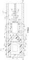
- FIGS. 1 and 2 one embodiment of a slip molding apparatus, according to the present invention, is shown generally at 10 in FIGS. 1 and 2 .
- the slip molding apparatus 10 is configured to be disposed in a pipe, generally indicated at 12, in FIG. 2 .
- the pipe 12 is generally cylindrical in shape and extending axially a predetermined distance.
- the pipe 12 has a generally circular cross-sectional shape, but may be any suitable shape.
- the pipe 12 has an interior surface 14.
- the pipe 12 also has a first open end 16 and a second open end 18 spaced axially from the first open end 16.
- the pipe 12 is made of a material such as metal, plastic, concrete, or the like for conveying a fluid such as water, oil, gas, etc. It should be appreciated that the pipe 12 illustrated in FIG. 2 is known in the art and is commercially available. It should also be appreciated that the pipe 12 illustrated in FIG. 2 is not intended to limit the scope of the present invention. It should further be appreciated that the slip molding apparatus 10 may be used with various other types of pipes, not specifically shown herein, without departing from the scope of the present invention.
- the slip molding apparatus 10 includes a dispense head, generally indicated at 20, for engaging the interior surface 14 of the pipe 12.
- the dispense head 20 has a body 21 that is generally cylindrical in shape. In one embodiment, the body 21 is generally circular in cross-sectional shape, but may be any suitable shape.
- the body 21 has a first or forward end 22 and a second or rearward end 24 spaced axially from the forward end 22. It should be appreciated that the body 21 may have a hollow interior (not shown) for receiving a lining material for lining the pipe 12, a control valve (not shown) to control flow of the lining material, or a mixing head (not shown) for the lining material.
- the body 12 may include a hydraulic or pneumatic piston (not shown) that pulls a rod (not shown) back, allowing multiple chemicals for the lining material to pass through orifices (not shown), at high pressure (approximately 6895 kPa to 17237 kPa) (1000 to 2,500 psi) that atomize the chemicals and enter a mixing chamber (not shown) to mix and be directed out from the dispense head 20.
- a hydraulic or pneumatic piston (not shown) that pulls a rod (not shown) back, allowing multiple chemicals for the lining material to pass through orifices (not shown), at high pressure (approximately 6895 kPa to 17237 kPa) (1000 to 2,500 psi) that atomize the chemicals and enter a mixing chamber (not shown) to mix and be directed out from the dispense head 20.
- the dispense head 20 also has a nozzle 26 extending axially from the rearward end 24 of the body 21 to dispense the material for lining the interior surface 14 of the pipe 12.
- the dispense head 20 also includes one or more arms 28 extending radially from the body 21 and one or more rotatable rollers 30 mounted to the arms 28 for allowing the body 21 to be centered within and roll along the interior surface 14 of the pipe 12.
- the dispense head 20 includes four arms 28 and four rollers 30 with one roller 30 being mounted to one arm 28.
- the arms 28 may be spaced axially and/or circumferentially along the body 21. It should be appreciated that the body 21 rolls along the interior surface 14 of the pipe 12.
- the dispense head 20 further includes an attachment 32 extending axially from the forward end 22 of the body 21 to allow attachment to a retracting cable 34 or the like to allow the dispense head 20 to be pulled along the interior surface 14 of the pipe 12.
- the attachment 32 may be of an eyelet type.
- the dispense head 20 also includes one or more chemical hoses 36 connected to the body 21 to supply the lining material to the dispense head 20. It should be appreciated that the chemical hoses 36 may be attached to the retracting cable 34 to allow the retracting cable 34 and chemical hoses 36 to be pulled together as a unit. It should also be appreciated that the chemical hoses 36 supply the chemicals for lining material to the body 21, which is dispensed from the nozzle 26 of the dispense head 20.
- the slip molding apparatus 10 further includes a slip mold, generally indicated at 38, to form the lining material on the interior surface 14 of the pipe 12.
- the slip mold 38 includes a body 40 having a generally cylindrical shape.
- the body 40 has a generally circular cross-sectional shape, but may be any suitable shape.
- the body 40 has a first or leading end 42 and a second or trailing end 44 spaced axially from the forward end 42.
- the forward end 42 is generally arcuate in shape to allow the lining material to flow over the body 40.
- the trailing end 44 has a diameter greater than a diameter of the leading end 42.
- the body 40 may be solid. It should be appreciated that the body 40 is used for forming the lining material. It should also be appreciated that the final internal diameter of the lining would be the diameter of the body 40 for the slip mold 38 used in the pipe 12. It should further be appreciated that different diameter bodies 40 may be used for the slip mold 38 to vary the thickness of the lining for the pipe 12.
- the slip mold 38 also includes a guide 46 for guiding the lining material dispensed by the dispense head 20 about the body 40.
- the diverter 46 has a generally inverted "V" shape.
- the guide 46 has a narrow or pointed end disposed about the nozzle 26 of the dispense head 20.
- the guide 46 may be connected to the nozzle 26 by a suitable mechanism such as fasteners (not shown), welding, or the like.
- the guide 46 has a wide or open end 48 that engages the interior surface 14 of the pipe 12.
- the guide 46 is supported on the body 40 by a suitable mechanism such as one or more braces 50. It should be appreciated that the braces 50 may be connected to the body 40 by a suitable mechanism such as fasteners (not shown), welding, or the like. It should also be appreciated that the slip mold 38 is pulled by the dispense head 20.
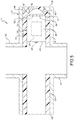
- the slip molding apparatus 10 includes one or more diverters 52 on the slip mold 38 and cooperating with the guide 46 to divert a flow of the lining material dispensed by the dispense head 20 about the slip mold 38.
- the diverters 52 are movable plates connected to the body 40 of the slip mold 38.
- the diverters 52 are operatively connected to an actuator 54 such as, for example, a solenoid having a piston that is extended or retracted. It should be appreciated that the actuator 54 pushes one or more of the diverter plates 52 into the lining material and cooperates with the guide 46 to block the flow of the lining material about a side of the body 40.
- the slip molding apparatus 10 may include a heater 56 attached to the slip mold 38.
- the heater 56 is a heating element disposed within the body 40 of the slip mold 38. It should be appreciated that the heater 56 may be connected by wires (not shown) to the braces 50 and retracting cable 34.
- the slip molding apparatus 10 further includes one or more cameras 58 disposed on the dispense head 20 and slip mold 38 to provide a view of the interior surface 40 of the pipe 12.
- a pair of cameras 58 are mounted to the forward end of the body 21 of the dispense head 20 and one camera 58 is mounted to the rearward end of the body 40 of the slip mold 38.
- the slip molding apparatus 10 also includes a remote controller 59 communicating with the cameras 58 for view by an operator. It should also be appreciated that the cameras 58 are connected by wires (not shown) to the retracting cable 34 and viewed by the operator remotely.
- the lining material could be a variety of materials such as concrete, cement, polyurethane, epoxy, or any polymer, such as one of the following classes of thermoplastic or thermoset polymers: any member from the group of polyesters, polyamide, polyethylene, polyethylene terephthalate, acrylonitrile, butadiene styrene, polymethyl methacrylate, cellulose acetate, cyclic olefin copolymers, fluoropolymers, polyoxymethylene, polyacrylates, polyacrylonitrile, polyaryletherketone, polyamide-imide, polybutylene terephthalate, polyurethanes, polyketone, polyetheretherketone, polyetherimide, polycarbonate, polymethylpentene, polyphenylene sulfide, polyphenylene oxide, polyphthalamide, polystyrene, polysulfone, polyvinyl chloride, and styrene-acrylonitrile, and any combinations thereof.
- the lining material includes reinforcing materials.
- the reinforcing materials include, but are not limited to, fiberglass windings or pieces, glass microspheres, mesh, wire, etc.
- An example of a suitable reinforcing material for the present invention is commercially available from BASF Corporation, 100 Campus Drive, Florham Park, NJ.
- the slip molding apparatus 10 is disposed in the pipe 12 that is being rehabilitated.
- the dispense head 20 and slip mold 38 are placed into the open end 16 of pipe 12.
- the lining material is dispensed through the chemical hoses 36, the dispense head 20, and out the nozzle 26.
- the operator moves the retracting cable 34 toward the other open end 18 of the pipe 12 to pull the dispense head 20.
- the dispense head 20 pulls the slip mold 38.
- the dispensed lining material is guided around the slip mold 38 by the guide 46 as the slip molding apparatus 10 is retracted or pulled along the pipe 12 by the retracting cable 34 and forms a lining 61 on the interior surface 14 of the pipe 12.
- the lining material is formulated such that it will cure while the slip mold 38 slips through the lining material, thereby forming the lining 61.
- the camera 58 on the slip mold 38 can be used by the operator to ensure complete coverage of the lining 61 on the interior surface 14 of the pipe 12.
- the rate of cure can be aided by the heater 56 to the slip mold 38. It should be appreciated that the flow rate of the lining material is controlled by the rate of retracting the slip molding apparatus 10.
- the operator can activate the actuator 54 and push the diverter 52 into the lining material, thereby blocking the lining material from entering the intersecting pipe 60.
- the operator can activate the actuator 54 and pull or retract the diverter 52 and continue to line the full pipe 12 with the lining 61. It should be appreciated that the amount of time the piston of the actuator 54 stays activated is controlled by the rate of the movement of the slip molding apparatus 10.
- the present invention further provides a method of using the slip molding apparatus 10 for lining the pipe 12.
- the method generally includes the steps of disposing the slip molding apparatus 10 including the dispense head 20 and the slip mold 38 within an interior of the pipe 12.
- the method includes the steps of engaging the interior surface 14 of the pipe 12 with the dispense head 20 and dispensing the lining material.
- the method includes the steps of supplying the lining material to and through the dispense head 20 with a supply or chemical hose 36 attached to the dispense head 20.
- the method includes the steps of pulling the slip mold 38 by the dispense head 20.
- the method includes the steps of viewing the interior surface 14 of the pipe 12 with at least one camera 58 disposed on the dispense head 20.
- the method includes the steps of guiding the lining material dispensed by the dispense head 20 about the slip mold 38 with the guide 46 connected to the dispense head 20 and the slip mold 38.
- the method includes the steps of communicating with the actuator 54 with the remote controller 59 and actuating the actuator 54 by an operator with the remote controller 59.
- the method includes the steps of blocking a flow of lining material dispensed by the dispense head 20 with a movable diverter 52 on the slip mold 38 cooperating with the guide 46.
- the method includes the steps of actuating and moving the diverter 52 between a retracted position and an extended position with the actuator 54 on the slip mold 38.
- the method includes the steps of heating the lining material with the heater 56 connected to the slip mold 38 to cure the lining material. It should be appreciated that the slip molding apparatus 10 may be used by various other methods, not specifically described herein.
- the slip molding apparatus 10 of the present invention has the ability to prevent flow into intersecting pipes 60 so that they are not blocked by the lining materials.
- the slip molding apparatus 10 of the present invention allows for precise flow rate calculations of the rehabilitated pipe 12.
- the slip molding apparatus 10 of the present invention has the ability to provide a variety of pipeline linings such, but not limited to, concrete, cement, polyurethane, epoxy, etc.
- the slip molding apparatus 10 of the present invention has the ability to add reinforcing materials to the lining such as, but not limited to, fiberglass windings or pieces, glass microspheres, mesh, wire, etc.
- the slip molding apparatus 10 of the present invention has the ability to apply leak detection wires during application.
- the slip molding apparatus 10 of the present invention has full contact to the inner surface of the pipe 12 that is being rehabilitated.
Landscapes
- Engineering & Computer Science (AREA)
- Mechanical Engineering (AREA)
- General Engineering & Computer Science (AREA)
- Chemical & Material Sciences (AREA)
- Ceramic Engineering (AREA)
- Lining Or Joining Of Plastics Or The Like (AREA)
- Moulds For Moulding Plastics Or The Like (AREA)
Claims (15)
- Gleitformvorrichtung (10) zum Auskleiden eines Rohres (12), umfassend:einen Abgabekopf (20), der angepasst ist, um mit einer Innenfläche (14) eines Rohres (12) in Eingriff zu kommen und ein Auskleidungsmaterial abzugeben;eine Gleitform (38), die von dem Abgabekopf (20) gezogen wird und ein Vorderende (42) und ein Nachlaufende (44) aufweist, wobei das Nachlaufende (44) einen größeren Durchmesser als ein Durchmesser des Vorderendes (42) aufweist;mindestens eine auf dem Abgabekopf (20) angeordnete Kamera (58), um einen Blick auf die Innenfläche (14) des Rohres (12) zu ermöglichen;eine Führung (46), die mit dem Abgabekopf (20) und der Gleitform (38) verbunden ist, um das vom Abgabekopf (20) abgegebene Auskleidungsmaterial um die Gleitform (38) zu führen; undgekennzeichnet durcheinen beweglichen Umlenker (52) auf der Gleitform (38), der mit der Führung (46) zusammenwirkt, um einen Fluss von Auskleidungsmaterial, das durch den Abgabekopf (20) abgegeben wird, um die Gleitform (38) herum umzuleiten.
- Gleitformvorrichtung (10) nach Anspruch 1, die einen Zuführschlauch (36) enthält, der an dem Abgabekopf (20) befestigt ist, um das Auskleidungsmaterial zu und durch den Abgabekopf (20) zu fördern.
- Gleitformvorrichtung (10) nach Ansprüchen 1 oder 2, die ein Stellglied (54) an der Gleitform (38) zum Betätigen und Bewegen des Umlenkers (52) zwischen einer eingefahrenen Position und einer ausgefahrenen Position beinhaltet.
- Gleitformvorrichtung (10) nach einem der Ansprüche 1-3, wobei der Umlenker (52) mindestens eine Umlenkplatte (52) beinhaltet.
- Gleitformvorrichtung (10) nach einem der Ansprüche 1-4, wobei die mindestens eine Kamera (58) eine Kamera (58) umfasst, die an einem Vorderende (42) des Ausgabekopfes (20) angeordnet ist.
- Gleitformvorrichtung (10) nach einem der Ansprüche 1-4, die mindestens eine Kamera (58) beinhaltet, die an einem Nachlaufende der Gleitform (38) angeordnet ist.
- Gleitformvorrichtung (10) nach einem der Ansprüche 1-6, die eine Vielzahl von Rollen (30) beinhaltet, die drehbar mit dem Abgabekopf (20) verbunden sind, um die Innenfläche (14) des Rohres (12) zu kontaktieren.
- Gleitformvorrichtung (10) nach einem der Ansprüche 1-7, die eine mit der Gleitform (38) verbundene Heizvorrichtung (56) zum Erwärmen des Auskleidungsmaterials beinhaltet.
- Gleitformvorrichtung (10) nach einem der Ansprüche 3-8, die eine mit dem Stellglied (54) verbundene Fernsteuerung (59) zum Betätigen des Stellglieds (54) durch einen Bediener beinhaltet.
- Verfahren zur Verwendung einer Gleitformvorrichtung (10) zum Auskleiden eines Rohres (19) mit einem Auskleidungsmaterial, wobei das Verfahren die Schritte umfasst:Anordnen einer Gleitformvorrichtung (10), die einen Abgabekopf (20) und eine Gleitform (38) in einem Innenraum (14) eines Rohres (12) beinhaltet;Eingriff der Innenfläche (14) des Rohres (12) mit dem Abgabekopf (20) und Abgabe eines Auskleidungsmaterials;Ziehen einer Gleitform (38) durch den Abgabekopf (20) und mit einem Vorderende (42) und einem Nachlaufende (44), wobei das Nachlaufende (44) einen größeren Durchmesser als ein Durchmesser des Vorderendes (42) aufweist;Betrachten der Innenfläche (14) des Rohres (12) mit mindestens einer Kamera (58), die auf dem Abgabekopf (20) angeordnet ist;Führen des vom Abgabekopf (20) abgegebenen Auskleidungsmaterials um die Gleitform (38) mit einer Führung (46), die mit dem Abgabekopf (20) und der Gleitform (38) verbunden ist; undgekennzeichnet durchUmleiten eines vom Abgabekopf (38) abgegebenen Flusses von Auskleidungsmaterial um die Gleitform (20) mit einem beweglichen Umlenker (52) auf der Gleitform (38), der mit der Führung (46) zusammenwirkt.
- Verfahren nach Anspruch 10, das die Schritte des Betätigens und Bewegens des Umlenkers (52) zwischen einer eingefahrenen Position und einer ausgefahrenen Position mit einem Stellglied (46) auf der Gleitform (38) beinhaltet.
- Verfahren nach Anspruch 11, das die Schritte der Kommunikation mit dem Stellglied mit einer Fernsteuerung (59) und der Betätigung des Stellglieds (46) durch einen Bediener mit der Fernsteuerung (59) beinhaltet.
- Verfahren nach einem der Ansprüche 10-12, das die Schritte des Erwärmens des Auskleidungsmaterials mit einer mit der Gleitform (38) verbundenen Heizvorrichtung (56) beinhaltet.
- Verfahren nach einem der Ansprüche 10-13, das die Schritte des Kontaktierens der Innenfläche (14) des Rohres (12) mit einer Vielzahl von Rollen (30), die drehbar mit dem Abgabekopf (20) verbunden sind, beinhaltet.
- Verfahren nach einem der Ansprüche 10-14, das die Schritte des Ziehens des Abgabekopfes (20) durch das Rohr (12) und des Bildens einer Auskleidung auf der Innenfläche (14) des Rohres (12) durch die Gleitform (38), die sich durch das abgegebene Auskleidungsmaterial bewegt, beinhaltet.
Priority Applications (1)
| Application Number | Priority Date | Filing Date | Title |
|---|---|---|---|
| PL15819870T PL3224011T3 (pl) | 2014-11-26 | 2015-11-24 | Urządzenie do formowania z mas lejnych do wykładania rur oraz sposób jego stosowania |
Applications Claiming Priority (2)
| Application Number | Priority Date | Filing Date | Title |
|---|---|---|---|
| US201462085034P | 2014-11-26 | 2014-11-26 | |
| PCT/IB2015/059105 WO2016084006A1 (en) | 2014-11-26 | 2015-11-24 | Slip molding apparatus for lining pipes and method of using same |
Publications (2)
| Publication Number | Publication Date |
|---|---|
| EP3224011A1 EP3224011A1 (de) | 2017-10-04 |
| EP3224011B1 true EP3224011B1 (de) | 2019-05-22 |
Family
ID=55069025
Family Applications (1)
| Application Number | Title | Priority Date | Filing Date |
|---|---|---|---|
| EP15819870.5A Active EP3224011B1 (de) | 2014-11-26 | 2015-11-24 | Schlickergussvorrichtung zur auskleidung von rohrleitungen und verfahren zur verwendung davon |
Country Status (8)
| Country | Link |
|---|---|
| US (1) | US10596584B2 (de) |
| EP (1) | EP3224011B1 (de) |
| KR (1) | KR102468983B1 (de) |
| CN (1) | CN107000250B (de) |
| CA (1) | CA2968500C (de) |
| MX (1) | MX375677B (de) |
| PL (1) | PL3224011T3 (de) |
| WO (1) | WO2016084006A1 (de) |
Families Citing this family (5)
| Publication number | Priority date | Publication date | Assignee | Title |
|---|---|---|---|---|
| CN110106961A (zh) * | 2019-06-06 | 2019-08-09 | 广东隆建工程有限公司 | 排水管道施工方法 |
| CN110359538A (zh) * | 2019-06-15 | 2019-10-22 | 广东一中建筑工程有限公司 | 给排水工程管道铺设方法 |
| CN112895111A (zh) * | 2021-01-14 | 2021-06-04 | 衡水瑟林科技有限公司 | 管道原位修复方法 |
| CN115056337A (zh) * | 2022-06-06 | 2022-09-16 | 中建八局第三建设有限公司 | 一种非破坏非开挖可调节混凝土管道内衬喷浆修复装置 |
| CN116658741B (zh) * | 2023-07-28 | 2023-09-26 | 东北大学 | 一种管道不停输内修复装置 |
Family Cites Families (21)
| Publication number | Priority date | Publication date | Assignee | Title |
|---|---|---|---|---|
| US2758352A (en) * | 1955-04-19 | 1956-08-14 | Perkins Pipe Linings Inc | Pipe lining apparatus |
| US3333311A (en) * | 1963-06-21 | 1967-08-01 | Pipe Linings Inc | Apparatus for lining pipe including spreader leaves with adjustably mounted spring means |
| US3655122A (en) * | 1970-10-20 | 1972-04-11 | George A Brown | Pipe line cleaner and sealer |
| US3966389A (en) * | 1972-12-27 | 1976-06-29 | Ameron, Inc. | Apparatus for troweling pipe lining material |
| US4256445A (en) * | 1978-10-12 | 1981-03-17 | Pingree Robert J | Trowel means for lining and smoothing the interior of pipes with a protective coating |
| JPS5676792A (en) * | 1979-11-22 | 1981-06-24 | Kankyo Kaihatsu Kk | Reinforcing and repairing device of burried pipe like as gas pipe |
| EP0233239B1 (de) * | 1985-08-15 | 1990-05-30 | Tate Pipe Lining Processes Limited | Verfahren und vorrichtung zur verkleidung von rohren |
| GB8629217D0 (en) * | 1986-12-06 | 1987-01-14 | Tate Pipe Lining Process Ltd | Lining pipes |
| SE8704210D0 (sv) * | 1987-10-29 | 1987-10-29 | Uponor Nv | Ror for infodring av tryckvattenledningar |
| US5019417A (en) * | 1989-08-15 | 1991-05-28 | Northcutt Gerald G | Pipe lining system |
| DE4119161A1 (de) * | 1991-06-11 | 1992-12-17 | Werner & Pfleiderer | Verfahren und vorrichtung zum auskleiden der innenwand eines kanalrohres |
| US5443377A (en) * | 1991-11-13 | 1995-08-22 | Mainlining Service, Inc. | Increased efficiency apparatus for lining a pipe with a cement mortar |
| DE4230586A1 (de) * | 1992-09-12 | 1994-03-17 | Breyer Gmbh Maschinenfabrik | Verfahren und Vorrichtung zum Sanieren von Rohrleitungen |
| GB2275981B (en) * | 1993-03-10 | 1997-03-12 | British Gas Plc | Apparatus and method for introducing sealant into a clearance |
| US5855676A (en) * | 1997-05-01 | 1999-01-05 | Virginia Tech Intellectual Properties, Inc. | Tube lining apparatus |
| US6514346B1 (en) * | 1998-03-25 | 2003-02-04 | Neuco, Inc. | Method and apparatus for inserting and propelling a coating device into and through live gas pipeline |
| WO2009052850A1 (de) * | 2007-10-24 | 2009-04-30 | Siegfried Schwert | Verfahren zum auskleiden einer rohrleitung oder eines kanals |
| GB2462607A (en) * | 2008-08-11 | 2010-02-17 | Dvs Technology Ltd | Pipelining apparatus and method |
| US20110076397A1 (en) | 2009-09-30 | 2011-03-31 | Rauch Edwin L | Pipe lining method and apparatus |
| US20110297243A1 (en) * | 2010-06-03 | 2011-12-08 | Lmk Enterprises, Inc. | Method and apparatus of lining a pipe |
| CN203348825U (zh) * | 2013-07-10 | 2013-12-18 | 顾和根 | 管道非开挖内衬修复翻新装置 |
-
2015
- 2015-11-24 EP EP15819870.5A patent/EP3224011B1/de active Active
- 2015-11-24 PL PL15819870T patent/PL3224011T3/pl unknown
- 2015-11-24 CA CA2968500A patent/CA2968500C/en active Active
- 2015-11-24 CN CN201580064556.XA patent/CN107000250B/zh active Active
- 2015-11-24 US US15/528,947 patent/US10596584B2/en active Active
- 2015-11-24 MX MX2017006897A patent/MX375677B/es active IP Right Grant
- 2015-11-24 KR KR1020177017024A patent/KR102468983B1/ko active Active
- 2015-11-24 WO PCT/IB2015/059105 patent/WO2016084006A1/en not_active Ceased
Non-Patent Citations (1)
| Title |
|---|
| None * |
Also Published As
| Publication number | Publication date |
|---|---|
| CA2968500C (en) | 2022-11-22 |
| WO2016084006A1 (en) | 2016-06-02 |
| EP3224011A1 (de) | 2017-10-04 |
| CA2968500A1 (en) | 2016-06-02 |
| MX2017006897A (es) | 2017-08-24 |
| CN107000250A (zh) | 2017-08-01 |
| US10596584B2 (en) | 2020-03-24 |
| MX375677B (es) | 2025-03-06 |
| KR20170086617A (ko) | 2017-07-26 |
| PL3224011T3 (pl) | 2019-10-31 |
| CN107000250B (zh) | 2020-11-06 |
| KR102468983B1 (ko) | 2022-11-22 |
| US20170266683A1 (en) | 2017-09-21 |
Similar Documents
| Publication | Publication Date | Title |
|---|---|---|
| EP3224011B1 (de) | Schlickergussvorrichtung zur auskleidung von rohrleitungen und verfahren zur verwendung davon | |
| KR101556503B1 (ko) | 환경 친화형 불침투성 막으로 파이프를 라이닝하기 위한 방법 및 장치 | |
| US10065359B2 (en) | Apparatus and method for lining a pipe | |
| WO2018209044A1 (en) | Plugging apparatus, system and method for pipe lining applications | |
| US8678039B2 (en) | Double layer conduit | |
| KR101474298B1 (ko) | 비굴착식 상하수도 보수 시스템 및 공법 | |
| KR101495705B1 (ko) | 비굴착식 상하수도 보수용 유체 분배 장치 | |
| CN101761664B (zh) | 节流阀及其在用以清洁泥浆输送管的设备和方法中的应用 | |
| KR100847227B1 (ko) | 피그를 이용한 배관 내면의 세정방법 및 그 장치 | |
| US20170356175A1 (en) | Drain unclogging system | |
| DE19836730C2 (de) | Vorrichtung zur Sanierung von rohrförmigen Gegenständen | |
| EP0861400A1 (de) | Auskleidung von rohren | |
| US11607705B2 (en) | Air purging apparatus for a coater | |
| DE2355724C2 (de) | Verfahren und Vorrichtung zum Verlegen eines thermoplastischen Rohres | |
| DE202009007391U1 (de) | Vorrichtung zum Auftragen eines Kunststoffmaterials auf die Oberfläche eines Rohrkörpers | |
| WO2016008589A1 (de) | Verfahren und vorrichtung zum sanieren einer in einen hauptkanal mündenden grundleitung | |
| AU2014218459A1 (en) | Apparatus and method for lining a pipe | |
| SE1350356A1 (sv) | Flexibel foderkonstruktion för reparation eller förstärkningav ett rör | |
| UA12716U (en) | In-pipe manipulator | |
| JP2015194171A (ja) | コイル成形体敷設方法、ライニング工法および更生管路 | |
| CN102439340A (zh) | 用于将阻塞装置引入到管道内的设备 |
Legal Events
| Date | Code | Title | Description |
|---|---|---|---|
| STAA | Information on the status of an ep patent application or granted ep patent |
Free format text: STATUS: THE INTERNATIONAL PUBLICATION HAS BEEN MADE |
|
| PUAI | Public reference made under article 153(3) epc to a published international application that has entered the european phase |
Free format text: ORIGINAL CODE: 0009012 |
|
| STAA | Information on the status of an ep patent application or granted ep patent |
Free format text: STATUS: REQUEST FOR EXAMINATION WAS MADE |
|
| 17P | Request for examination filed |
Effective date: 20170626 |
|
| AK | Designated contracting states |
Kind code of ref document: A1 Designated state(s): AL AT BE BG CH CY CZ DE DK EE ES FI FR GB GR HR HU IE IS IT LI LT LU LV MC MK MT NL NO PL PT RO RS SE SI SK SM TR |
|
| AX | Request for extension of the european patent |
Extension state: BA ME |
|
| DAV | Request for validation of the european patent (deleted) | ||
| DAX | Request for extension of the european patent (deleted) | ||
| GRAP | Despatch of communication of intention to grant a patent |
Free format text: ORIGINAL CODE: EPIDOSNIGR1 |
|
| STAA | Information on the status of an ep patent application or granted ep patent |
Free format text: STATUS: GRANT OF PATENT IS INTENDED |
|
| RIC1 | Information provided on ipc code assigned before grant |
Ipc: F16L 55/1645 20060101ALI20180618BHEP Ipc: B05C 7/08 20060101ALI20180618BHEP Ipc: B28B 19/00 20060101AFI20180618BHEP |
|
| INTG | Intention to grant announced |
Effective date: 20180718 |
|
| GRAS | Grant fee paid |
Free format text: ORIGINAL CODE: EPIDOSNIGR3 |
|
| GRAJ | Information related to disapproval of communication of intention to grant by the applicant or resumption of examination proceedings by the epo deleted |
Free format text: ORIGINAL CODE: EPIDOSDIGR1 |
|
| GRAL | Information related to payment of fee for publishing/printing deleted |
Free format text: ORIGINAL CODE: EPIDOSDIGR3 |
|
| STAA | Information on the status of an ep patent application or granted ep patent |
Free format text: STATUS: REQUEST FOR EXAMINATION WAS MADE |
|
| INTC | Intention to grant announced (deleted) | ||
| GRAP | Despatch of communication of intention to grant a patent |
Free format text: ORIGINAL CODE: EPIDOSNIGR1 |
|
| STAA | Information on the status of an ep patent application or granted ep patent |
Free format text: STATUS: GRANT OF PATENT IS INTENDED |
|
| INTG | Intention to grant announced |
Effective date: 20190116 |
|
| GRAA | (expected) grant |
Free format text: ORIGINAL CODE: 0009210 |
|
| STAA | Information on the status of an ep patent application or granted ep patent |
Free format text: STATUS: THE PATENT HAS BEEN GRANTED |
|
| AK | Designated contracting states |
Kind code of ref document: B1 Designated state(s): AL AT BE BG CH CY CZ DE DK EE ES FI FR GB GR HR HU IE IS IT LI LT LU LV MC MK MT NL NO PL PT RO RS SE SI SK SM TR |
|
| REG | Reference to a national code |
Ref country code: GB Ref legal event code: FG4D |
|
| REG | Reference to a national code |
Ref country code: CH Ref legal event code: EP |
|
| REG | Reference to a national code |
Ref country code: IE Ref legal event code: FG4D |
|
| REG | Reference to a national code |
Ref country code: DE Ref legal event code: R096 Ref document number: 602015030920 Country of ref document: DE |
|
| REG | Reference to a national code |
Ref country code: AT Ref legal event code: REF Ref document number: 1135547 Country of ref document: AT Kind code of ref document: T Effective date: 20190615 |
|
| REG | Reference to a national code |
Ref country code: NL Ref legal event code: FP |
|
| REG | Reference to a national code |
Ref country code: LT Ref legal event code: MG4D |
|
| PG25 | Lapsed in a contracting state [announced via postgrant information from national office to epo] |
Ref country code: PT Free format text: LAPSE BECAUSE OF FAILURE TO SUBMIT A TRANSLATION OF THE DESCRIPTION OR TO PAY THE FEE WITHIN THE PRESCRIBED TIME-LIMIT Effective date: 20190922 Ref country code: AL Free format text: LAPSE BECAUSE OF FAILURE TO SUBMIT A TRANSLATION OF THE DESCRIPTION OR TO PAY THE FEE WITHIN THE PRESCRIBED TIME-LIMIT Effective date: 20190522 Ref country code: LT Free format text: LAPSE BECAUSE OF FAILURE TO SUBMIT A TRANSLATION OF THE DESCRIPTION OR TO PAY THE FEE WITHIN THE PRESCRIBED TIME-LIMIT Effective date: 20190522 Ref country code: FI Free format text: LAPSE BECAUSE OF FAILURE TO SUBMIT A TRANSLATION OF THE DESCRIPTION OR TO PAY THE FEE WITHIN THE PRESCRIBED TIME-LIMIT Effective date: 20190522 Ref country code: SE Free format text: LAPSE BECAUSE OF FAILURE TO SUBMIT A TRANSLATION OF THE DESCRIPTION OR TO PAY THE FEE WITHIN THE PRESCRIBED TIME-LIMIT Effective date: 20190522 Ref country code: NO Free format text: LAPSE BECAUSE OF FAILURE TO SUBMIT A TRANSLATION OF THE DESCRIPTION OR TO PAY THE FEE WITHIN THE PRESCRIBED TIME-LIMIT Effective date: 20190822 Ref country code: HR Free format text: LAPSE BECAUSE OF FAILURE TO SUBMIT A TRANSLATION OF THE DESCRIPTION OR TO PAY THE FEE WITHIN THE PRESCRIBED TIME-LIMIT Effective date: 20190522 |
|
| PG25 | Lapsed in a contracting state [announced via postgrant information from national office to epo] |
Ref country code: LV Free format text: LAPSE BECAUSE OF FAILURE TO SUBMIT A TRANSLATION OF THE DESCRIPTION OR TO PAY THE FEE WITHIN THE PRESCRIBED TIME-LIMIT Effective date: 20190522 Ref country code: BG Free format text: LAPSE BECAUSE OF FAILURE TO SUBMIT A TRANSLATION OF THE DESCRIPTION OR TO PAY THE FEE WITHIN THE PRESCRIBED TIME-LIMIT Effective date: 20190822 Ref country code: RS Free format text: LAPSE BECAUSE OF FAILURE TO SUBMIT A TRANSLATION OF THE DESCRIPTION OR TO PAY THE FEE WITHIN THE PRESCRIBED TIME-LIMIT Effective date: 20190522 |
|
| PG25 | Lapsed in a contracting state [announced via postgrant information from national office to epo] |
Ref country code: CZ Free format text: LAPSE BECAUSE OF FAILURE TO SUBMIT A TRANSLATION OF THE DESCRIPTION OR TO PAY THE FEE WITHIN THE PRESCRIBED TIME-LIMIT Effective date: 20190522 Ref country code: RO Free format text: LAPSE BECAUSE OF FAILURE TO SUBMIT A TRANSLATION OF THE DESCRIPTION OR TO PAY THE FEE WITHIN THE PRESCRIBED TIME-LIMIT Effective date: 20190522 Ref country code: EE Free format text: LAPSE BECAUSE OF FAILURE TO SUBMIT A TRANSLATION OF THE DESCRIPTION OR TO PAY THE FEE WITHIN THE PRESCRIBED TIME-LIMIT Effective date: 20190522 Ref country code: DK Free format text: LAPSE BECAUSE OF FAILURE TO SUBMIT A TRANSLATION OF THE DESCRIPTION OR TO PAY THE FEE WITHIN THE PRESCRIBED TIME-LIMIT Effective date: 20190522 Ref country code: SK Free format text: LAPSE BECAUSE OF FAILURE TO SUBMIT A TRANSLATION OF THE DESCRIPTION OR TO PAY THE FEE WITHIN THE PRESCRIBED TIME-LIMIT Effective date: 20190522 |
|
| REG | Reference to a national code |
Ref country code: DE Ref legal event code: R097 Ref document number: 602015030920 Country of ref document: DE |
|
| PG25 | Lapsed in a contracting state [announced via postgrant information from national office to epo] |
Ref country code: SM Free format text: LAPSE BECAUSE OF FAILURE TO SUBMIT A TRANSLATION OF THE DESCRIPTION OR TO PAY THE FEE WITHIN THE PRESCRIBED TIME-LIMIT Effective date: 20190522 |
|
| PLBE | No opposition filed within time limit |
Free format text: ORIGINAL CODE: 0009261 |
|
| STAA | Information on the status of an ep patent application or granted ep patent |
Free format text: STATUS: NO OPPOSITION FILED WITHIN TIME LIMIT |
|
| PG25 | Lapsed in a contracting state [announced via postgrant information from national office to epo] |
Ref country code: TR Free format text: LAPSE BECAUSE OF FAILURE TO SUBMIT A TRANSLATION OF THE DESCRIPTION OR TO PAY THE FEE WITHIN THE PRESCRIBED TIME-LIMIT Effective date: 20190522 |
|
| 26N | No opposition filed |
Effective date: 20200225 |
|
| PG25 | Lapsed in a contracting state [announced via postgrant information from national office to epo] |
Ref country code: SI Free format text: LAPSE BECAUSE OF FAILURE TO SUBMIT A TRANSLATION OF THE DESCRIPTION OR TO PAY THE FEE WITHIN THE PRESCRIBED TIME-LIMIT Effective date: 20190522 |
|
| REG | Reference to a national code |
Ref country code: CH Ref legal event code: PL |
|
| PG25 | Lapsed in a contracting state [announced via postgrant information from national office to epo] |
Ref country code: LU Free format text: LAPSE BECAUSE OF NON-PAYMENT OF DUE FEES Effective date: 20191124 Ref country code: CH Free format text: LAPSE BECAUSE OF NON-PAYMENT OF DUE FEES Effective date: 20191130 Ref country code: LI Free format text: LAPSE BECAUSE OF NON-PAYMENT OF DUE FEES Effective date: 20191130 Ref country code: MC Free format text: LAPSE BECAUSE OF FAILURE TO SUBMIT A TRANSLATION OF THE DESCRIPTION OR TO PAY THE FEE WITHIN THE PRESCRIBED TIME-LIMIT Effective date: 20190522 |
|
| REG | Reference to a national code |
Ref country code: BE Ref legal event code: MM Effective date: 20191130 |
|
| PG25 | Lapsed in a contracting state [announced via postgrant information from national office to epo] |
Ref country code: IE Free format text: LAPSE BECAUSE OF NON-PAYMENT OF DUE FEES Effective date: 20191124 Ref country code: FR Free format text: LAPSE BECAUSE OF NON-PAYMENT OF DUE FEES Effective date: 20191130 Ref country code: ES Free format text: LAPSE BECAUSE OF FAILURE TO SUBMIT A TRANSLATION OF THE DESCRIPTION OR TO PAY THE FEE WITHIN THE PRESCRIBED TIME-LIMIT Effective date: 20190522 |
|
| PG25 | Lapsed in a contracting state [announced via postgrant information from national office to epo] |
Ref country code: BE Free format text: LAPSE BECAUSE OF NON-PAYMENT OF DUE FEES Effective date: 20191130 |
|
| PG25 | Lapsed in a contracting state [announced via postgrant information from national office to epo] |
Ref country code: CY Free format text: LAPSE BECAUSE OF FAILURE TO SUBMIT A TRANSLATION OF THE DESCRIPTION OR TO PAY THE FEE WITHIN THE PRESCRIBED TIME-LIMIT Effective date: 20190522 |
|
| PG25 | Lapsed in a contracting state [announced via postgrant information from national office to epo] |
Ref country code: GR Free format text: LAPSE BECAUSE OF FAILURE TO SUBMIT A TRANSLATION OF THE DESCRIPTION OR TO PAY THE FEE WITHIN THE PRESCRIBED TIME-LIMIT Effective date: 20190522 Ref country code: IS Free format text: LAPSE BECAUSE OF FAILURE TO SUBMIT A TRANSLATION OF THE DESCRIPTION OR TO PAY THE FEE WITHIN THE PRESCRIBED TIME-LIMIT Effective date: 20190922 |
|
| PG25 | Lapsed in a contracting state [announced via postgrant information from national office to epo] |
Ref country code: MT Free format text: LAPSE BECAUSE OF FAILURE TO SUBMIT A TRANSLATION OF THE DESCRIPTION OR TO PAY THE FEE WITHIN THE PRESCRIBED TIME-LIMIT Effective date: 20190522 Ref country code: HU Free format text: LAPSE BECAUSE OF FAILURE TO SUBMIT A TRANSLATION OF THE DESCRIPTION OR TO PAY THE FEE WITHIN THE PRESCRIBED TIME-LIMIT; INVALID AB INITIO Effective date: 20151124 |
|
| REG | Reference to a national code |
Ref country code: AT Ref legal event code: UEP Ref document number: 1135547 Country of ref document: AT Kind code of ref document: T Effective date: 20190522 |
|
| PG25 | Lapsed in a contracting state [announced via postgrant information from national office to epo] |
Ref country code: MK Free format text: LAPSE BECAUSE OF FAILURE TO SUBMIT A TRANSLATION OF THE DESCRIPTION OR TO PAY THE FEE WITHIN THE PRESCRIBED TIME-LIMIT Effective date: 20190522 |
|
| PGFP | Annual fee paid to national office [announced via postgrant information from national office to epo] |
Ref country code: NL Payment date: 20241126 Year of fee payment: 10 |
|
| PGFP | Annual fee paid to national office [announced via postgrant information from national office to epo] |
Ref country code: DE Payment date: 20241128 Year of fee payment: 10 |
|
| PGFP | Annual fee paid to national office [announced via postgrant information from national office to epo] |
Ref country code: GB Payment date: 20241126 Year of fee payment: 10 |
|
| PGFP | Annual fee paid to national office [announced via postgrant information from national office to epo] |
Ref country code: IT Payment date: 20241125 Year of fee payment: 10 |
|
| PGFP | Annual fee paid to national office [announced via postgrant information from national office to epo] |
Ref country code: AT Payment date: 20251118 Year of fee payment: 11 |
|
| PGFP | Annual fee paid to national office [announced via postgrant information from national office to epo] |
Ref country code: PL Payment date: 20251028 Year of fee payment: 11 |