EP3224416B1 - Procédé et dispositif de compaction d'un lit de ballast d'une voie ferrée - Google Patents
Procédé et dispositif de compaction d'un lit de ballast d'une voie ferrée Download PDFInfo
- Publication number
- EP3224416B1 EP3224416B1 EP15808080.4A EP15808080A EP3224416B1 EP 3224416 B1 EP3224416 B1 EP 3224416B1 EP 15808080 A EP15808080 A EP 15808080A EP 3224416 B1 EP3224416 B1 EP 3224416B1
- Authority
- EP
- European Patent Office
- Prior art keywords
- lifting
- switch
- measuring system
- lining unit
- switch component
- Prior art date
- Legal status (The legal status is an assumption and is not a legal conclusion. Google has not performed a legal analysis and makes no representation as to the accuracy of the status listed.)
- Active
Links
Images


Classifications
-
- E—FIXED CONSTRUCTIONS
- E01—CONSTRUCTION OF ROADS, RAILWAYS, OR BRIDGES
- E01B—PERMANENT WAY; PERMANENT-WAY TOOLS; MACHINES FOR MAKING RAILWAYS OF ALL KINDS
- E01B27/00—Placing, renewing, working, cleaning, or taking-up the ballast, with or without concurrent work on the track; Devices therefor; Packing sleepers
- E01B27/12—Packing sleepers, with or without concurrent work on the track; Compacting track-carrying ballast
- E01B27/13—Packing sleepers, with or without concurrent work on the track
- E01B27/16—Sleeper-tamping machines
- E01B27/17—Sleeper-tamping machines combined with means for lifting, levelling or slewing the track
-
- E—FIXED CONSTRUCTIONS
- E01—CONSTRUCTION OF ROADS, RAILWAYS, OR BRIDGES
- E01B—PERMANENT WAY; PERMANENT-WAY TOOLS; MACHINES FOR MAKING RAILWAYS OF ALL KINDS
- E01B27/00—Placing, renewing, working, cleaning, or taking-up the ballast, with or without concurrent work on the track; Devices therefor; Packing sleepers
- E01B27/12—Packing sleepers, with or without concurrent work on the track; Compacting track-carrying ballast
- E01B27/20—Compacting the material of the track-carrying ballastway, e.g. by vibrating the track, by surface vibrators
-
- E—FIXED CONSTRUCTIONS
- E01—CONSTRUCTION OF ROADS, RAILWAYS, OR BRIDGES
- E01B—PERMANENT WAY; PERMANENT-WAY TOOLS; MACHINES FOR MAKING RAILWAYS OF ALL KINDS
- E01B35/00—Applications of measuring apparatus or devices for track-building purposes
-
- E—FIXED CONSTRUCTIONS
- E01—CONSTRUCTION OF ROADS, RAILWAYS, OR BRIDGES
- E01B—PERMANENT WAY; PERMANENT-WAY TOOLS; MACHINES FOR MAKING RAILWAYS OF ALL KINDS
- E01B35/00—Applications of measuring apparatus or devices for track-building purposes
- E01B35/06—Applications of measuring apparatus or devices for track-building purposes for measuring irregularities in longitudinal direction
-
- E—FIXED CONSTRUCTIONS
- E01—CONSTRUCTION OF ROADS, RAILWAYS, OR BRIDGES
- E01B—PERMANENT WAY; PERMANENT-WAY TOOLS; MACHINES FOR MAKING RAILWAYS OF ALL KINDS
- E01B2203/00—Devices for working the railway-superstructure
- E01B2203/10—Track-lifting or-lining devices or methods
-
- E—FIXED CONSTRUCTIONS
- E01—CONSTRUCTION OF ROADS, RAILWAYS, OR BRIDGES
- E01B—PERMANENT WAY; PERMANENT-WAY TOOLS; MACHINES FOR MAKING RAILWAYS OF ALL KINDS
- E01B2203/00—Devices for working the railway-superstructure
- E01B2203/12—Tamping devices
- E01B2203/125—Tamping devices adapted for switches or crossings
Definitions
- the invention relates to a method for controlling the lifting and straightening unit of a track-traveling switch tamping machine for compacting the ballast bedding of a track, in particular in the area of a switch, with a tamping unit, with a lifting and straightening unit that includes a roller tong, a roller tong locking cylinder with a closing path sensor, a lifting cylinder the lifting force, a hook depth cylinder with depth sensor for a lifting hook and a guide-straightening wheel for guiding the lifting-straightening unit along a rail, the position of switch components, such as switch drive boxes, rails and frogs, during the advance of the switch tamping machine with the help of a lift -Righting unit in the working direction upstream switch component measuring system is measured and temporarily stored in the transverse direction of the track depending on location, and the position of the sleepers and the intermediate compartments in the working direction is recorded and temporarily stored.
- switch components such as switch drive boxes, rails and frogs
- a device for compacting the ballast bedding of a track, in particular in the area of a switch, with a switch tamping machine which has a tamping unit, a lifting and straightening unit, a roller tong, a roller tong locking cylinder with a closing travel sensor, a lifting cylinder with the lifting force, a hook depth cylinder with a depth transmitter for a lifting hook and a guide-straightening wheel for straightening the track position and is equipped with a switch component measuring system upstream of the lifting-straightening unit in the working direction for the location-dependent measurement of the position of switch components.
- Such a device is from DE 3923733 A1 known.
- a lifting and straightening unit that can be moved in the longitudinal direction of the machine is from the CH 536901 A known.
- Turnout tamping machines are machines for correcting the track position of turnouts.
- measuring systems are used that measure the actual track height, the actual track direction and the actual cant position of the track during work and compare them with specified target values.
- the track grid is raised and laterally aligned until the difference between the specified target position and the actual position is zero.
- the switch is set by compressing the ballast under the sleepers with the help of a switch tamping unit.
- the track grid is lifted and straightened using hydraulic lifting and straightening cylinders with proportional or servo controls.
- Turnouts have a continuous track and a branching track as a special feature.
- Trains are led into the branch via so-called tongues or held on the continuous main line.
- the so-called centerpiece is located at the intersection of the continuous track and the branching track.
- the railway wheel In the area of the frog, the railway wheel must be guided from the rail of the continuous line to the rail of the branching line. Guide rails are provided so that the unguided wheel in the interruption area rolls safely into the branch or into the continuous main line.
- the tamping units can be moved sideways and, because of the sloping long sleepers, the tamping units can be rotated.
- the tamping tines can also be designed to be pivotable, at least in part.
- the rail is gripped at the head with roller tongs and lifted into the geometrical target position.
- the roller tongs are often not used because of the crossing rails and in the centerpiece possible. So that these points can also be machined (set up), lifting hooks that can be extended laterally and are height-adjustable in depth are also provided.
- the universal machines In addition to pure turnout tamping machines and track tamping machines, there are also universal machines that can be used both for track and turnout areas.
- the universal machines often have two work cabins.
- the switch tamping cabin is opposite to the working direction with regard to its viewing direction. From the switch tamping cabin, the machine operator controls the position of the tamping unit, the pick, he selects the roller tongs or the lifting hook or the position of the lifting hook as well as the point of application of the same on the rail head or on the rail foot, depending on the circumstances and discretion.
- the lifting device can also be moved in the longitudinal direction of the track.
- the turnout tamping cabin is chosen primarily because of the better view of the lifting and straightening unit of the turnout tamping machine.
- the line tamping machine is in the working direction from the viewing direction.
- the manual setting of the lifting device, the choice of roller tongs or lifting hook, the positioning of the lifting hook and the Force application point, as well as the displacement of the lifting device in the longitudinal direction of the track requires time.
- Distance measuring devices using odometers or other methods are also known. Since the target track geometry is defined in terms of the curved length of the track, the current position of the machine in terms of the track kilometrage must be recorded.
- the invention is therefore based on the object of specifying a method for automatically controlling the roller tongs and the lifting hook for lifting switches by switch tamping machines, with which the operating speed can be increased and the susceptibility to errors can be minimized.
- the invention solves the problem in that the lifting and straightening unit is guided in a longitudinally displaceable manner in the machine's longitudinal direction and the switch component measuring system has switch component detection sensors that the recorded values for the working position of the roller tongs and the lifting hook are queried so that a test is carried out on the basis of these values Whether the roller tongs can be used in this working position and, if the roller tongs cannot be used, a check is carried out on the basis of these values to determine whether the lifting hook can grip the rail head and, if this is not possible, that the lifting hook may be shifted in the longitudinal direction of the machine takes place that the lifting hook comes to stand on the rail foot in an intermediate compartment and that the lifting is carried out after gripping the rail with the lifting and straightening unit, with a Gr eifposition determined for the lifting and straightening unit and this gripping position is automatically approached before closing the roller tongs or before gripping the rail with the lifting hook, in particular by transverse displacement, longitudinal displacement and depth adjustment of the lifting and straightening unit
- the position of the switch components is detected with the switch component measuring system arranged upstream of the lifting and straightening unit in the working direction and stored as a function of the path.
- Any number of practically one-dimensional snapshots of the track cross-section can be made in plan view and stored in a database.
- a digital image of the track and, in particular, the switch components can be created from the stored data.
- the lifting and straightening unit is automatically shifted accordingly in the longitudinal direction of the track along a guide on the machine frame in order to approach a suitable point of application for the lifting and straightening tool.
- the suitable lifting and straightening tool is selected depending on the measured values of the switch component measuring system, i.e.
- roller tongs and lifting hook is automatically selected by a control or regulation.
- a control or regulation As a result of these measures, one of the two work cabins can be omitted.
- the automatic control of the roller clamp and lifting hook compensates for the deteriorated view of the roller clamp and lifting hook from the track tamping cabin and increases the working speed.
- a video system can also be used to monitor the roller tongs and lifting hooks.
- the position of the track components in particular the switch components (position of the rails, the frog, the wing rails, the switch blades, the drive boxes for the switch blades, etc.) with respect to the lifting and straightening unit in the working direction is recorded in advance depending on the path.
- the detection of these steel components can be done, for example, with the help of a series of inductive or capacitive proximity sensors, ultrasonic sensors or a laser scanner (equidistant scanning, for example, every 5 cm).
- the position of the switch components is stored as a function of the path and transposed by a computer system to the position of the roller tongs or the lifting hook.
- the path progress of the machine is measured using a path measuring device, for example an odometer.
- the previous measurements are evaluated for the respective position of the lifting and straightening unit. If there is not enough space to manipulate with the roller pliers, then it is determined automatically switched to the lifting hook. Depending on the previous measurement and the temporarily stored data for the current location of the lifting and straightening unit, the extension position of the lifting hook and the rail head as the point of application are selected first. By measuring the extended position and the closing path of the lifting hook, it can be concluded whether the head has been securely gripped by the hook or not. If the closing path is not sufficient, the hook is automatically opened again. If the lifting hook is not located above the intermediate compartment, the lifting and straightening unit is moved in the longitudinal direction of the track until the lifting hook is located above the intermediate compartment. At this new position the attempt is made to close the rail head again.
- the rail foot is selected as the point of application of force. If the roller tong does not grip the rail head successfully, this can be determined by measuring the displacement of the hydraulic locking cylinder, then the lifting and straightening unit is moved to a position in the longitudinal direction of the track where it can be closed. If there is no such position, the lifting hook with the point of application on the rail foot is automatically activated. On the side of the lifting devices (always on the outside of the rail), the measuring device records the position of the turnout components in the transverse direction of the track; the reference point is the rail track on which the turnout tamping machine and the lifting and straightening device are running.
- a gripping position for the lifting / straightening system is determined from the position of the switch components recorded with the switch component measuring system and this gripping position is automatically approached before closing the roller tongs or before gripping the rail with the lifting hook, in particular by transverse displacement, longitudinal displacement and depth adjustment of the lifting and straightening system .
- the switch component measuring system detects the position of the switch components preferably with a sensor strip comprising a large number of individual sensors, which sensor strip is arranged upstream of the lifting and straightening unit running transversely to the machine longitudinal direction and with a number of inductive sensors and / or capacitive sensors and / or laser distance sensors and / or Ultrasonic distance sensors is equipped.
- the switch component measuring system can also record the position of the switch components with at least one laser scanner.
- a device for compacting the ballast bedding of a track, in particular in the area of a switch, with a switch tamping machine, with a tamping unit, with a lifting and straightening unit that includes a roller tong, a roller tong locking cylinder with a closing travel sensor, a lifting cylinder with the lifting force, a hook depth cylinder with a depth sensor for one Has lifting hook and a guide-straightening wheel for guiding the lifting-straightening unit along a rail, for straightening the track position, and with a switch component measuring system upstream of the lifting-straightening unit in the working direction for the location-dependent measurement of the position of switch components in the transverse direction of the track, is characterized by the fact that the Lifting-straightening unit is guided longitudinally displaceably on the machine frame in the longitudinal direction of the machine and has the switch component measuring system with switch component detection sensors that the switch component measuring system measure the position of switch components depending on location and z can be temporarily stored and the position of
- the hook depth cylinder with depth sensor is assigned to the lifting hook of the lifting and straightening unit
- the roller tongs of the lifting and straightening unit can be assigned to the roller tong locking cylinder with closing travel sensor and can be assigned to the lifting
- a transverse shift cylinder with a displacement sensor can be assigned to the straightening unit.
- a particularly simple and robust switch component measuring system is obtained when it comprises a sensor strip, preferably comprising a plurality of individual sensors, which is provided on the switch tamping machine, aligned transversely to the longitudinal direction of the machine.
- the sensor strip can comprise a multiplicity of individual sensors arranged one behind the other in the longitudinal direction of the strip, that is to say in a row.
- the switch component measuring system can include inductive sensors, capacitive sensors, laser distance sensors and / or ultrasonic distance sensors or, if appropriate, at least one laser scanner.
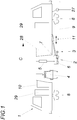
- a turnout tamping machine 1 has a tamping unit 4 and a track lifting / straightening unit 2 with a lifting cylinder 5, roller tongs 6, a lifting hook 7 and a measuring device 3 ( Fig. 1 ).
- the lifting and straightening unit can be moved in the longitudinal direction 11 of the track by means of a hydraulic cylinder.
- the switch tamping machine can be moved on the rail 9 via drives 8.
- the turnout tamping machine 1 is controlled from the work booth 10 arranged behind the tamping unit 4 in the working direction C.
- the work cabin 10 and the driving cabs can be entered via side doors 29.
- the arc length of the track is determined with a distance measuring device 27.
- the otherwise usual second switch tamping cabin 28 can be omitted in the embodiment according to the invention.
- the switch component measuring system 3 for the location-dependent measurement of the position of switch components is arranged upstream of the lifting and straightening unit 2 in the working direction C.
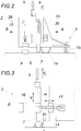
- the lifting and straightening unit ( Fig. 2 ) has a roller tong 6, a roller tong lock cylinder 12 with a closing travel sensor 26, a lifting cylinder 5 with the lifting force F H , a hook depth cylinder 13 with a depth sensor 30 for the lifting hook, a switch component measuring system 3 with switch component detection sensors 15, a lifting hook 7 and a guide straightening wheel 14.
- the lifting and straightening unit 2 is guided along the rail 9 by means of wheels 14.
- FIG. 3 of the lifting and straightening unit 2 shows in particular the guide device 16 for the transverse displacement of the lifting hook 7, the lifting hook displacement cylinder 17 with displacement sensor 31, the guide and straightening wheel 14, the lifting cylinder 5 and the guide rail 9.
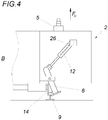
- the view according to Fig. 4 of the lifting and straightening unit 2 shows the roller tong 6, the roller tong locking cylinder 12 with the closing travel sensor 26, the lifting cylinder 5 with the lifting force F H , the guide rail 9 and the guide straightening wheel 14.
- Fig. 5 shows the schematic top view of a switch 22 to be straightened with the essential switch components, namely the tongue drives 18, the tongues 19, the guide rails 20, the frog 21, the wing rails 25, the continuous main strand 23, the sleepers 32, the intermediate compartments 33 and the branching line 24.
- the tongue area 19 is shown schematically.
- the obstacle position D is recorded
- K corresponds to the track position of the switch component measuring system 3 which, in the exemplary embodiment given, consists of individual switch component detection sensors 15.
- the switch component detection sensors 15 are arranged in two rows running next to one another, the individual sensors of adjacent sensor rows being staggered with gaps.
- 19 shows the tongue, 9 shows the continuous rail, E indicates the area in which the roller pliers 6 is used, F the position in which the lifting hook 7 must be used.
- C indicates the working direction.
- the vertical axis D shows the obstacle position and the horizontal axis K shows the track position at which the measuring device 3 was located at the time of the measurement.
- the crosses in the diagram indicate which of the distance sensors 15 has actively detected a switch component.
- M indicates the required free space from which the roller pliers 6 can be used.
- the frog area L is shown schematically.
- the obstacle position D is specified in the transverse direction
- K corresponds to the track position of the measuring device 3, which in the specified exemplary embodiment consists of individual distance sensors 15.
- E indicates the area in which the roller pliers 6 is used
- F the position in which the lifting hook 7 must be used.
- C indicates the working direction.
- the vertical axis D shows the obstacle position
- the horizontal axis K shows the track position at which the measuring device 3 was located at the time of the measurement.
- the crosses in the diagram indicate which of the distance sensors 15 has actively detected a switch component.
- M indicates the required free space from which the roller pliers 6 can be used.
- 21 represents the centerpiece and 25 the wing rails.
Landscapes
- Engineering & Computer Science (AREA)
- Architecture (AREA)
- Civil Engineering (AREA)
- Structural Engineering (AREA)
- Machines For Laying And Maintaining Railways (AREA)
Claims (12)
- Procédé de pilotage d'une unité de levage et de pose d'une machine de bourrage d'aiguillage (1) adaptée (8) à une voie ferrée, pour densifier la litière de ballast d'une voie ferrée,
surtout au voisinage d'un aiguillage, avec une unité de bourrage (4), avec une unité de levage et de pose (2) qui présente une pince à roue (6), un crochet de levage (7), un cylindre de serrage de la pince (12) avec un capteur de desserrage (26), un cylindre de levage (5) exerçant la force de levage (FH), un cylindre profond à crochet (13) avec une sonde (30) pour la profondeur du crochet (7) et une roue directrice de guidage (14) pour guider l'unité de levage et de pose (2) le long d'un rail (9),
où la position perpendiculairement à la voie ferrée indépendamment du lieu, des composants de l'aiguillage, comme surtout les boîtes d'entraînement d'aiguillage (18), les rails (9) et le cœur d'aiguillage (21), est mesurée et enregistrée pendant la progression de la machine de bourrage, à l'aide d'un appareil de mesure (3) des composants d'aiguillage, disposé devant l'unité de levage et de pose (2) dans le sens d'opération (C),
et où la position des traverses (32) et des intervalles (33) dans le sens d'opération est détectée et enregistrée,
caractérisé en ce que l'unité de levage et de pose (2) est apte à être guidée longitudinalement (11) dans le sens de la longueur de la machine et l'appareil de mesure (3) des composants d'aiguillage présente des capteurs de détection (15) de composants d'aiguillage,
en ce que les valeurs détectées pour la position d'opération de la pince à roue (6) et du crochet de levage (7) sont consultées,
en ce qu'un examen sur la base de ces valeurs s'ensuit à savoir si la pince à roue (6) peut être installée à la position d'opération (J, M) et, si la pince à roue (6) ne peut pas être installée à la position d'opération (J, M), un examen s'ensuit à savoir si le crochet de levage (7) peut saisir la tête du rail et si cela n'est pas non plus possible, en ce qu'un déplacement du crochet de levage (7) dans la direction de la longueur de la machine s'ensuit le cas échéant, de sorte que le crochet de levage (7) vient reposer au pied du rail au niveau d'un intervalle (33) et que le levage est effectué après une saisie du rail par l'unité de levage et de pose (2),
où une position de saisie pour l'unité de levage et de pose (2) à partir de la position des composants d'aiguillage, détectée par l'appareil de mesure des composants d'aiguillage, est permise et cette position de saisie est démarrée automatiquement avant le serrage de la pince à roues ou avant la saisie du rail par le crochet de levage (7), surtout grâce à une poussée transversale, longitudinale et à un déplacement en profondeur de l'unité de levage et de pose (2). - Procédé selon la revendication 1, caractérisé en ce que l'appareil de mesure des composants d'aiguillage (3) détecte la position des composants d'aiguillage avec une barre de capteurs, comprenant de préférence plusieurs capteurs de détection de composants d'aiguillage, laquelle barre de capteurs est disposée transversalement à la direction de la longueur de la machine s'étendant le long de l'unité de levage et de pose dans le sens d'opération (C).
- Procédé selon la revendication 1 ou 2, caractérisé en ce que l'appareil de mesure des composants d'aiguillage (3) détecte la position des composants d'aiguillage avec une rangée de capteurs inductifs (15) ou capacitifs (15).
- Procédé selon l'une des revendications 1 ou 2, caractérisé en ce que l'appareil de mesure des composants d'aiguillage (3) détecte la position des composants d'aiguillage avec une rangée de capteurs de distance par laser (15) ou par échographie (15).
- Procédé selon l'une des revendications 1 ou 2, caractérisé en ce que l'appareil de mesure des composants d'aiguillage (3) détecte la position des composants d'aiguillage avec au moins un scanner laser.
- Système pour la densification du ballast d'une voie ferrée, surtout au voisinage d'un aiguillage, avec une machine de bourrage d'aiguillage (1), avec une unité de bourrage (4), avec une unité de levage et de pose (2) qui présente une pince à roue (6), un crochet de levage (7), un cylindre de serrage de la pince (12) avec un capteur de desserrage (26), un cylindre de levage (5) exerçant la force de levage (FH), un cylindre profond à crochet (13) avec une sonde (30) pour la profondeur du crochet (7) et une roue directrice de guidage (14) pour guider l'unité de levage et de pose (2) le long d'un rail, pour rectifier l'emplacement de la voie ferrée, et avec un appareil de mesure (3) des composants d'aiguillage disposé devant l'unité de levage et de pose (2) dans le sens d'opération (C) pour une mesure de la position des composants d'aiguillage perpendiculairement à la voie ferrée, indépendamment du lieu,
caractérisé en ce que l'unité de levage et de pose (2) est apte à être guidée longitudinalement au châssis de la machine dans le sens de la longueur de la machine et l'appareil de mesure (3) des composants d'aiguillage présente des capteurs de détection de composants d'aiguillage (15),
en ce que l'appareil de mesure (3) des composants d'aiguillage peut mesurer et enregistrer la position des composants d'aiguillage indépendamment du lieu et la position des traverses (32) et des intervalles (33) dans le sens d'opération (C) peut être détectée et enregistrée et en ce que les valeurs détectées pour la position d'opération de la pince à roue (6) et du crochet de levage (7) peuvent être consultées,
en ce qu'un examen sur la base de ces valeurs peut s'ensuivre à savoir si la pince à roue (6) peut être installée à la position d'opération (J, M) et, si la pince à roue (6) ne peut pas être installée à la position d'opération (J, M), un examen peut s'ensuivre à savoir si le crochet de levage (7) peut saisir la tête du rail et si cela n'est pas non plus possible, en ce qu'un déplacement du crochet de levage (7) dans la direction de la longueur de la machine peut s'ensuivre le cas échéant, de sorte que le crochet de levage (7) vient reposer au pied du rail au niveau d'un intervalle (33) et que le levage peut être effectué après une saisie du rail par l'unité de levage et de pose (2),
où une position de saisie pour l'unité de levage et de pose (2) à partir de la position des composants d'aiguillage, détectée par l'appareil de mesure des composants d'aiguillage (3), peut être permise et cette position de saisie peut être démarrée automatiquement avant le serrage de la pince à roues ou avant la saisie du rail par le crochet de levage (7), surtout grâce à une poussée transversale, longitudinale et à un déplacement en profondeur de l'unité de levage et de pose (2). - Système selon la revendication 6, caractérisé en ce que le cylindre de serrage de la pince à roue (12) est subordonné à la pince à roue (6) de l'unité de levage et de pose (2) avec un capteur de serrage (26).
- Système selon l'une des revendications 6 ou 7, caractérisé en ce qu'un cylindre de poussée transversale (17) est subordonné à l'unité de levage et de pose (2) avec un capteur de course de poussée (31).
- Système selon l'une des revendications 6 à 8, caractérisé en ce que l'appareil de mesure des composants d'aiguillage (3) disposé devant l'unité de levage et de pose (2) dans le sens d'opération (C) comprend une barre de capteurs, comprenant de préférence plusieurs capteurs individuels.
- Système selon la revendication 9, caractérisé en ce que la barre de capteurs (3) comprend plusieurs capteurs individuels (15) disposés l'un derrière l'autre dans la direction de la longueur de la barre.
- Système selon la revendication 10, caractérisé en ce que les capteurs individuels (15) disposés les uns derrière les autres dans la direction de la longueur de la barre sont disposés sur deux rangées ou plus, s'étendant l'une à côté de l'autre.
- Système selon l'une des revendications 6 à 8, caractérisé en ce que l'appareil de mesure des composants d'aiguillage (3) comprend des capteurs inductifs, des capteurs capacitifs, des capteurs de distance par laser et/ou des capteurs de distance échographiques respectivement le cas échéant au moins un scanner laser.
Applications Claiming Priority (2)
| Application Number | Priority Date | Filing Date | Title |
|---|---|---|---|
| ATA50862/2014A AT516590B1 (de) | 2014-11-28 | 2014-11-28 | Verfahren und Vorrichtung zum Verdichten der Schotterbettung eines Gleises |
| PCT/AT2015/050301 WO2016081971A1 (fr) | 2014-11-28 | 2015-11-26 | Procédé et dispositif de compaction d'un lit de ballast d'une voie ferrée |
Publications (2)
| Publication Number | Publication Date |
|---|---|
| EP3224416A1 EP3224416A1 (fr) | 2017-10-04 |
| EP3224416B1 true EP3224416B1 (fr) | 2021-03-10 |
Family
ID=54848358
Family Applications (1)
| Application Number | Title | Priority Date | Filing Date |
|---|---|---|---|
| EP15808080.4A Active EP3224416B1 (fr) | 2014-11-28 | 2015-11-26 | Procédé et dispositif de compaction d'un lit de ballast d'une voie ferrée |
Country Status (8)
| Country | Link |
|---|---|
| US (1) | US10550525B2 (fr) |
| EP (1) | EP3224416B1 (fr) |
| CN (1) | CN107208383A (fr) |
| AT (1) | AT516590B1 (fr) |
| AU (1) | AU2015354375A1 (fr) |
| CA (1) | CA2968590A1 (fr) |
| RU (1) | RU2674726C1 (fr) |
| WO (1) | WO2016081971A1 (fr) |
Families Citing this family (12)
| Publication number | Priority date | Publication date | Assignee | Title |
|---|---|---|---|---|
| AT516590B1 (de) * | 2014-11-28 | 2017-01-15 | System 7 - Railsupport GmbH | Verfahren und Vorrichtung zum Verdichten der Schotterbettung eines Gleises |
| EP3390723B1 (fr) * | 2015-12-17 | 2020-02-05 | Siemens Mobility Pty Ltd. | Système de mesure de déplacement de voie ferrée et procédé de maintenance proactive |
| AT519739B1 (de) | 2017-05-12 | 2018-10-15 | Plasser & Theurer Export Von Bahnbaumaschinen Gmbh | Verfahren zum Steuern einer Gleisbaumaschine |
| AT520824B1 (de) * | 2018-05-24 | 2019-08-15 | Plasser & Theurer Export Von Bahnbaumaschinen Gmbh | Verfahren und Maschine zum Unterstopfen eines Gleises im Bereich einer Weiche |
| AT521263B1 (de) * | 2018-08-20 | 2019-12-15 | Hp3 Real Gmbh | Verfahren zur Einzelfehlerbehebung |
| AT521990B1 (de) * | 2018-12-27 | 2022-07-15 | Plasser & Theurer Export Von Bahnbaumaschinen Gmbh | Verfahren und Gleisbaumaschine zur Bearbeitung eines Schottergleises |
| AT524193B1 (de) * | 2020-09-10 | 2024-01-15 | Hp3 Real Gmbh | Gleisstopfmaschine zum Verdichten der Schotterbettung eines Gleises |
| AT17436U1 (de) | 2020-12-02 | 2022-04-15 | Hp3 Real Gmbh | Verfahren zur automatischen autonomen Steuerung einer Stopfmaschine |
| CN112647368B (zh) * | 2020-12-21 | 2023-01-13 | 湖州生力液压有限公司 | 一种便携式且可调节角度的液压捣固机的使用方法 |
| AT525706B1 (de) * | 2021-11-22 | 2024-05-15 | Plasser & Theurer Export Von Bahnbaumaschinen Gmbh | Verfahren zum Betreiben einer Stopfmaschine |
| CN117385678A (zh) * | 2023-11-10 | 2024-01-12 | 株洲时代电子技术有限公司 | 一种道岔自动对镐控制系统及道岔捣固车 |
| AT527599B1 (de) | 2024-03-21 | 2025-04-15 | Hp3 Real Gmbh | Vollautomatisch arbeitende Gleisbaumaschine |
Family Cites Families (19)
| Publication number | Priority date | Publication date | Assignee | Title |
|---|---|---|---|---|
| CH536901A (fr) | 1971-12-03 | 1973-05-15 | Matisa Materiel Ind Sa | Dispositif pour le déplacement aussi bien vertical que latéral d'une section de voie ferrée |
| AT356165B (de) * | 1978-05-11 | 1980-04-10 | Plasser Bahnbaumasch Franz | Gleisstopfmaschine mit gleishebe- und seiten- richtvorrichtung, insbesondere fuer weichen- bereiche |
| SU1116108A1 (ru) * | 1983-06-15 | 1984-09-30 | Всесоюзный Ордена Трудового Красного Знамени Научно-Исследовательский Институт Железнодорожного Транспорта | Устройство управлени выправкой железнодорожного пути |
| AT387607B (de) * | 1987-07-08 | 1989-02-27 | Plasser Bahnbaumasch Franz | Fahrbare gleisstopf-, hebe- und richtmaschine fuer den weichen- und kreuzungsbereich |
| AT391903B (de) * | 1989-01-26 | 1990-12-27 | Plasser Bahnbaumasch Franz | Fahrbare gleisbearbeitungsmaschine mit einer einrichtung zur steuerung der arbeits-position ihrer arbeits-aggregate bzw. -werkzeuge |
| EP0518845B1 (fr) * | 1991-06-12 | 1995-04-12 | Franz Plasser Bahnbaumaschinen-Industriegesellschaft m.b.H. | Méthode et machine de compactage de ballast pour voies ferrées |
| CZ285403B6 (cs) * | 1995-03-16 | 1999-08-11 | Franz Plasser Bahnbaumaschinen-Industriegesellschaft M. B. H. | Pracovní vozidlo pro provádění kolejových stavebních prací |
| CN2340801Y (zh) * | 1997-12-24 | 1999-09-29 | 铁道部株洲电力机车研究所 | 一种自动拨道、抄平、捣固车 |
| AT5768U3 (de) * | 2002-07-29 | 2003-09-25 | Plasser Bahnbaumasch Franz | Stopfmaschine |
| AT5839U3 (de) * | 2002-09-25 | 2003-09-25 | Plasser Bahnbaumasch Franz | Maschine und verfahren zum unterstopfen von schwellen eines gleises |
| CN2761675Y (zh) * | 2005-01-14 | 2006-03-01 | 林凤君 | 道岔捣固机自动传感式液压勾轨装置 |
| KR20090087883A (ko) * | 2006-12-11 | 2009-08-18 | 프란츠 플라세 바흔바우마쉬넨-인두스트리게젤샤프트 엠. 베. 하 | 트랙 하부의 발라스트를 패킹하기 위한 탬핑 머신 |
| AT508755B1 (de) * | 2010-03-01 | 2011-04-15 | Plasser Bahnbaumasch Franz | Stopfmaschine mit einer zusatzhebeeinrichtung |
| AT509461B1 (de) * | 2010-09-27 | 2011-09-15 | Plasser Bahnbaumasch Franz | Stopfmaschine |
| PL2902546T3 (pl) * | 2014-01-30 | 2018-03-30 | Hp3 Real Gmbh | Urządzenie do zagęszczania podsypki z tłucznia toru kolejowego |
| AT516590B1 (de) * | 2014-11-28 | 2017-01-15 | System 7 - Railsupport GmbH | Verfahren und Vorrichtung zum Verdichten der Schotterbettung eines Gleises |
| AT516671B1 (de) * | 2014-12-22 | 2017-01-15 | System 7 - Railsupport GmbH | Stopfaggregat für eine Gleisstopfmaschine |
| AT516827B1 (de) * | 2015-06-02 | 2016-09-15 | System 7 - Railsupport GmbH | Stopfmaschine zum Verdichten der Schotterbettung eines Gleises |
| AT518023B1 (de) * | 2015-12-02 | 2018-04-15 | Plasser & Theurer Export Von Bahnbaumaschinen Gmbh | Stopfmaschine sowie Verfahren zur Durchführung einer Lagekorrektur eines Gleises |
-
2014
- 2014-11-28 AT ATA50862/2014A patent/AT516590B1/de active
-
2015
- 2015-11-26 CA CA2968590A patent/CA2968590A1/fr not_active Abandoned
- 2015-11-26 US US15/525,575 patent/US10550525B2/en active Active
- 2015-11-26 CN CN201580061901.4A patent/CN107208383A/zh active Pending
- 2015-11-26 EP EP15808080.4A patent/EP3224416B1/fr active Active
- 2015-11-26 RU RU2017122481A patent/RU2674726C1/ru active
- 2015-11-26 AU AU2015354375A patent/AU2015354375A1/en not_active Abandoned
- 2015-11-26 WO PCT/AT2015/050301 patent/WO2016081971A1/fr not_active Ceased
Non-Patent Citations (1)
| Title |
|---|
| None * |
Also Published As
| Publication number | Publication date |
|---|---|
| CN107208383A (zh) | 2017-09-26 |
| CA2968590A1 (fr) | 2016-06-02 |
| AT516590A1 (de) | 2016-06-15 |
| AU2015354375A1 (en) | 2017-05-25 |
| US20170328013A1 (en) | 2017-11-16 |
| US10550525B2 (en) | 2020-02-04 |
| RU2674726C1 (ru) | 2018-12-12 |
| EP3224416A1 (fr) | 2017-10-04 |
| AT516590B1 (de) | 2017-01-15 |
| WO2016081971A1 (fr) | 2016-06-02 |
Similar Documents
| Publication | Publication Date | Title |
|---|---|---|
| EP3224416B1 (fr) | Procédé et dispositif de compaction d'un lit de ballast d'une voie ferrée | |
| AT391903B (de) | Fahrbare gleisbearbeitungsmaschine mit einer einrichtung zur steuerung der arbeits-position ihrer arbeits-aggregate bzw. -werkzeuge | |
| EP4144915B1 (fr) | Procédé pour la commande d'un engin de pose de voie | |
| EP3204557B1 (fr) | Bourreuse mécanique servant à compacter le lit de ballast d'une voie | |
| DE3904179C2 (de) | Fahrbare Gleisstopf-, Hebe- und Richtmaschine zum Heben und/oder Seitwärtsverschieben eines Gleises im Weichen- und Kreuzungsbereich | |
| DE3313207C2 (fr) | ||
| EP3303703B1 (fr) | Bourreuse destinée au tassement du lit de ballast d'une voie ferroviaire | |
| US8433462B2 (en) | Drone vehicle | |
| EP4256133B1 (fr) | Procédé de commande autonome automatique d'une machine de bourrage de voies | |
| EP4337829B1 (fr) | Machine de bourrage pour compacter le lit de ballast d'une voie ferrée | |
| EP3009564A1 (fr) | Machine de bourrage destinee a comprimer le lit de ballast d'une voie ferree | |
| DE3838109A1 (de) | Verfahren und gleisfahrbare weichen-nivellier-, stopf- und richt-maschinenanordnung zur durcharbeitung in weichenbereichen | |
| DE2056273B2 (de) | Fahrbare Einrichtung zur Behandlung der Schotterbettung und der Kleineisenteile eines Gleises |
Legal Events
| Date | Code | Title | Description |
|---|---|---|---|
| STAA | Information on the status of an ep patent application or granted ep patent |
Free format text: STATUS: THE INTERNATIONAL PUBLICATION HAS BEEN MADE |
|
| PUAI | Public reference made under article 153(3) epc to a published international application that has entered the european phase |
Free format text: ORIGINAL CODE: 0009012 |
|
| STAA | Information on the status of an ep patent application or granted ep patent |
Free format text: STATUS: REQUEST FOR EXAMINATION WAS MADE |
|
| 17P | Request for examination filed |
Effective date: 20170407 |
|
| AK | Designated contracting states |
Kind code of ref document: A1 Designated state(s): AL AT BE BG CH CY CZ DE DK EE ES FI FR GB GR HR HU IE IS IT LI LT LU LV MC MK MT NL NO PL PT RO RS SE SI SK SM TR |
|
| AX | Request for extension of the european patent |
Extension state: BA ME |
|
| DAV | Request for validation of the european patent (deleted) | ||
| DAX | Request for extension of the european patent (deleted) | ||
| STAA | Information on the status of an ep patent application or granted ep patent |
Free format text: STATUS: EXAMINATION IS IN PROGRESS |
|
| 17Q | First examination report despatched |
Effective date: 20180525 |
|
| GRAP | Despatch of communication of intention to grant a patent |
Free format text: ORIGINAL CODE: EPIDOSNIGR1 |
|
| STAA | Information on the status of an ep patent application or granted ep patent |
Free format text: STATUS: GRANT OF PATENT IS INTENDED |
|
| INTG | Intention to grant announced |
Effective date: 20201208 |
|
| GRAS | Grant fee paid |
Free format text: ORIGINAL CODE: EPIDOSNIGR3 |
|
| GRAA | (expected) grant |
Free format text: ORIGINAL CODE: 0009210 |
|
| STAA | Information on the status of an ep patent application or granted ep patent |
Free format text: STATUS: THE PATENT HAS BEEN GRANTED |
|
| AK | Designated contracting states |
Kind code of ref document: B1 Designated state(s): AL AT BE BG CH CY CZ DE DK EE ES FI FR GB GR HR HU IE IS IT LI LT LU LV MC MK MT NL NO PL PT RO RS SE SI SK SM TR |
|
| REG | Reference to a national code |
Ref country code: GB Ref legal event code: FG4D Free format text: NOT ENGLISH |
|
| REG | Reference to a national code |
Ref country code: AT Ref legal event code: REF Ref document number: 1369928 Country of ref document: AT Kind code of ref document: T Effective date: 20210315 Ref country code: CH Ref legal event code: EP |
|
| REG | Reference to a national code |
Ref country code: DE Ref legal event code: R096 Ref document number: 502015014393 Country of ref document: DE |
|
| REG | Reference to a national code |
Ref country code: IE Ref legal event code: FG4D Free format text: LANGUAGE OF EP DOCUMENT: GERMAN |
|
| REG | Reference to a national code |
Ref country code: CH Ref legal event code: PK Free format text: BERICHTIGUNGEN |
|
| RIN2 | Information on inventor provided after grant (corrected) |
Inventor name: LICHTBERGER, BERNHARD |
|
| REG | Reference to a national code |
Ref country code: LT Ref legal event code: MG9D |
|
| PG25 | Lapsed in a contracting state [announced via postgrant information from national office to epo] |
Ref country code: HR Free format text: LAPSE BECAUSE OF FAILURE TO SUBMIT A TRANSLATION OF THE DESCRIPTION OR TO PAY THE FEE WITHIN THE PRESCRIBED TIME-LIMIT Effective date: 20210310 Ref country code: GR Free format text: LAPSE BECAUSE OF FAILURE TO SUBMIT A TRANSLATION OF THE DESCRIPTION OR TO PAY THE FEE WITHIN THE PRESCRIBED TIME-LIMIT Effective date: 20210611 Ref country code: FI Free format text: LAPSE BECAUSE OF FAILURE TO SUBMIT A TRANSLATION OF THE DESCRIPTION OR TO PAY THE FEE WITHIN THE PRESCRIBED TIME-LIMIT Effective date: 20210310 Ref country code: BG Free format text: LAPSE BECAUSE OF FAILURE TO SUBMIT A TRANSLATION OF THE DESCRIPTION OR TO PAY THE FEE WITHIN THE PRESCRIBED TIME-LIMIT Effective date: 20210610 Ref country code: NO Free format text: LAPSE BECAUSE OF FAILURE TO SUBMIT A TRANSLATION OF THE DESCRIPTION OR TO PAY THE FEE WITHIN THE PRESCRIBED TIME-LIMIT Effective date: 20210610 Ref country code: LT Free format text: LAPSE BECAUSE OF FAILURE TO SUBMIT A TRANSLATION OF THE DESCRIPTION OR TO PAY THE FEE WITHIN THE PRESCRIBED TIME-LIMIT Effective date: 20210310 |
|
| REG | Reference to a national code |
Ref country code: NL Ref legal event code: MP Effective date: 20210310 |
|
| PG25 | Lapsed in a contracting state [announced via postgrant information from national office to epo] |
Ref country code: SE Free format text: LAPSE BECAUSE OF FAILURE TO SUBMIT A TRANSLATION OF THE DESCRIPTION OR TO PAY THE FEE WITHIN THE PRESCRIBED TIME-LIMIT Effective date: 20210310 Ref country code: LV Free format text: LAPSE BECAUSE OF FAILURE TO SUBMIT A TRANSLATION OF THE DESCRIPTION OR TO PAY THE FEE WITHIN THE PRESCRIBED TIME-LIMIT Effective date: 20210310 Ref country code: RS Free format text: LAPSE BECAUSE OF FAILURE TO SUBMIT A TRANSLATION OF THE DESCRIPTION OR TO PAY THE FEE WITHIN THE PRESCRIBED TIME-LIMIT Effective date: 20210310 |
|
| PG25 | Lapsed in a contracting state [announced via postgrant information from national office to epo] |
Ref country code: NL Free format text: LAPSE BECAUSE OF FAILURE TO SUBMIT A TRANSLATION OF THE DESCRIPTION OR TO PAY THE FEE WITHIN THE PRESCRIBED TIME-LIMIT Effective date: 20210310 |
|
| PG25 | Lapsed in a contracting state [announced via postgrant information from national office to epo] |
Ref country code: EE Free format text: LAPSE BECAUSE OF FAILURE TO SUBMIT A TRANSLATION OF THE DESCRIPTION OR TO PAY THE FEE WITHIN THE PRESCRIBED TIME-LIMIT Effective date: 20210310 Ref country code: CZ Free format text: LAPSE BECAUSE OF FAILURE TO SUBMIT A TRANSLATION OF THE DESCRIPTION OR TO PAY THE FEE WITHIN THE PRESCRIBED TIME-LIMIT Effective date: 20210310 Ref country code: SM Free format text: LAPSE BECAUSE OF FAILURE TO SUBMIT A TRANSLATION OF THE DESCRIPTION OR TO PAY THE FEE WITHIN THE PRESCRIBED TIME-LIMIT Effective date: 20210310 |
|
| PG25 | Lapsed in a contracting state [announced via postgrant information from national office to epo] |
Ref country code: SK Free format text: LAPSE BECAUSE OF FAILURE TO SUBMIT A TRANSLATION OF THE DESCRIPTION OR TO PAY THE FEE WITHIN THE PRESCRIBED TIME-LIMIT Effective date: 20210310 Ref country code: RO Free format text: LAPSE BECAUSE OF FAILURE TO SUBMIT A TRANSLATION OF THE DESCRIPTION OR TO PAY THE FEE WITHIN THE PRESCRIBED TIME-LIMIT Effective date: 20210310 Ref country code: PL Free format text: LAPSE BECAUSE OF FAILURE TO SUBMIT A TRANSLATION OF THE DESCRIPTION OR TO PAY THE FEE WITHIN THE PRESCRIBED TIME-LIMIT Effective date: 20210310 Ref country code: PT Free format text: LAPSE BECAUSE OF FAILURE TO SUBMIT A TRANSLATION OF THE DESCRIPTION OR TO PAY THE FEE WITHIN THE PRESCRIBED TIME-LIMIT Effective date: 20210712 Ref country code: IS Free format text: LAPSE BECAUSE OF FAILURE TO SUBMIT A TRANSLATION OF THE DESCRIPTION OR TO PAY THE FEE WITHIN THE PRESCRIBED TIME-LIMIT Effective date: 20210710 |
|
| REG | Reference to a national code |
Ref country code: DE Ref legal event code: R097 Ref document number: 502015014393 Country of ref document: DE |
|
| PLBE | No opposition filed within time limit |
Free format text: ORIGINAL CODE: 0009261 |
|
| STAA | Information on the status of an ep patent application or granted ep patent |
Free format text: STATUS: NO OPPOSITION FILED WITHIN TIME LIMIT |
|
| PG25 | Lapsed in a contracting state [announced via postgrant information from national office to epo] |
Ref country code: AL Free format text: LAPSE BECAUSE OF FAILURE TO SUBMIT A TRANSLATION OF THE DESCRIPTION OR TO PAY THE FEE WITHIN THE PRESCRIBED TIME-LIMIT Effective date: 20210310 Ref country code: ES Free format text: LAPSE BECAUSE OF FAILURE TO SUBMIT A TRANSLATION OF THE DESCRIPTION OR TO PAY THE FEE WITHIN THE PRESCRIBED TIME-LIMIT Effective date: 20210310 Ref country code: DK Free format text: LAPSE BECAUSE OF FAILURE TO SUBMIT A TRANSLATION OF THE DESCRIPTION OR TO PAY THE FEE WITHIN THE PRESCRIBED TIME-LIMIT Effective date: 20210310 |
|
| 26N | No opposition filed |
Effective date: 20211213 |
|
| PG25 | Lapsed in a contracting state [announced via postgrant information from national office to epo] |
Ref country code: SI Free format text: LAPSE BECAUSE OF FAILURE TO SUBMIT A TRANSLATION OF THE DESCRIPTION OR TO PAY THE FEE WITHIN THE PRESCRIBED TIME-LIMIT Effective date: 20210310 |
|
| PG25 | Lapsed in a contracting state [announced via postgrant information from national office to epo] |
Ref country code: IS Free format text: LAPSE BECAUSE OF FAILURE TO SUBMIT A TRANSLATION OF THE DESCRIPTION OR TO PAY THE FEE WITHIN THE PRESCRIBED TIME-LIMIT Effective date: 20210710 |
|
| PG25 | Lapsed in a contracting state [announced via postgrant information from national office to epo] |
Ref country code: MC Free format text: LAPSE BECAUSE OF FAILURE TO SUBMIT A TRANSLATION OF THE DESCRIPTION OR TO PAY THE FEE WITHIN THE PRESCRIBED TIME-LIMIT Effective date: 20210310 |
|
| REG | Reference to a national code |
Ref country code: CH Ref legal event code: PL |
|
| PG25 | Lapsed in a contracting state [announced via postgrant information from national office to epo] |
Ref country code: LU Free format text: LAPSE BECAUSE OF NON-PAYMENT OF DUE FEES Effective date: 20211126 Ref country code: BE Free format text: LAPSE BECAUSE OF NON-PAYMENT OF DUE FEES Effective date: 20211130 |
|
| REG | Reference to a national code |
Ref country code: BE Ref legal event code: MM Effective date: 20211130 |
|
| PG25 | Lapsed in a contracting state [announced via postgrant information from national office to epo] |
Ref country code: LI Free format text: LAPSE BECAUSE OF NON-PAYMENT OF DUE FEES Effective date: 20211130 Ref country code: CH Free format text: LAPSE BECAUSE OF NON-PAYMENT OF DUE FEES Effective date: 20211130 |
|
| PG25 | Lapsed in a contracting state [announced via postgrant information from national office to epo] |
Ref country code: IE Free format text: LAPSE BECAUSE OF NON-PAYMENT OF DUE FEES Effective date: 20211126 |
|
| REG | Reference to a national code |
Ref country code: AT Ref legal event code: MM01 Ref document number: 1369928 Country of ref document: AT Kind code of ref document: T Effective date: 20211126 |
|
| PG25 | Lapsed in a contracting state [announced via postgrant information from national office to epo] |
Ref country code: AT Free format text: LAPSE BECAUSE OF NON-PAYMENT OF DUE FEES Effective date: 20211126 |
|
| PG25 | Lapsed in a contracting state [announced via postgrant information from national office to epo] |
Ref country code: HU Free format text: LAPSE BECAUSE OF FAILURE TO SUBMIT A TRANSLATION OF THE DESCRIPTION OR TO PAY THE FEE WITHIN THE PRESCRIBED TIME-LIMIT; INVALID AB INITIO Effective date: 20151126 |
|
| P01 | Opt-out of the competence of the unified patent court (upc) registered |
Effective date: 20230428 |
|
| PG25 | Lapsed in a contracting state [announced via postgrant information from national office to epo] |
Ref country code: CY Free format text: LAPSE BECAUSE OF FAILURE TO SUBMIT A TRANSLATION OF THE DESCRIPTION OR TO PAY THE FEE WITHIN THE PRESCRIBED TIME-LIMIT Effective date: 20210310 |
|
| PG25 | Lapsed in a contracting state [announced via postgrant information from national office to epo] |
Ref country code: MK Free format text: LAPSE BECAUSE OF FAILURE TO SUBMIT A TRANSLATION OF THE DESCRIPTION OR TO PAY THE FEE WITHIN THE PRESCRIBED TIME-LIMIT Effective date: 20210310 |
|
| PG25 | Lapsed in a contracting state [announced via postgrant information from national office to epo] |
Ref country code: MT Free format text: LAPSE BECAUSE OF FAILURE TO SUBMIT A TRANSLATION OF THE DESCRIPTION OR TO PAY THE FEE WITHIN THE PRESCRIBED TIME-LIMIT Effective date: 20210310 |
|
| PG25 | Lapsed in a contracting state [announced via postgrant information from national office to epo] |
Ref country code: TR Free format text: LAPSE BECAUSE OF FAILURE TO SUBMIT A TRANSLATION OF THE DESCRIPTION OR TO PAY THE FEE WITHIN THE PRESCRIBED TIME-LIMIT Effective date: 20210310 |
|
| PGFP | Annual fee paid to national office [announced via postgrant information from national office to epo] |
Ref country code: DE Payment date: 20251111 Year of fee payment: 11 |
|
| PGFP | Annual fee paid to national office [announced via postgrant information from national office to epo] |
Ref country code: GB Payment date: 20251110 Year of fee payment: 11 |
|
| PGFP | Annual fee paid to national office [announced via postgrant information from national office to epo] |
Ref country code: IT Payment date: 20251121 Year of fee payment: 11 |
|
| PGFP | Annual fee paid to national office [announced via postgrant information from national office to epo] |
Ref country code: FR Payment date: 20251124 Year of fee payment: 11 |