EP3224491B1 - Radrückhaltesystem - Google Patents
Radrückhaltesystem Download PDFInfo
- Publication number
- EP3224491B1 EP3224491B1 EP15862539.2A EP15862539A EP3224491B1 EP 3224491 B1 EP3224491 B1 EP 3224491B1 EP 15862539 A EP15862539 A EP 15862539A EP 3224491 B1 EP3224491 B1 EP 3224491B1
- Authority
- EP
- European Patent Office
- Prior art keywords
- connector
- nuts
- wheel
- studs
- locking part
- Prior art date
- Legal status (The legal status is an assumption and is not a legal conclusion. Google has not performed a legal analysis and makes no representation as to the accuracy of the status listed.)
- Active
Links
Images


Classifications
-
- B—PERFORMING OPERATIONS; TRANSPORTING
- B60—VEHICLES IN GENERAL
- B60B—VEHICLE WHEELS; CASTORS; AXLES FOR WHEELS OR CASTORS; INCREASING WHEEL ADHESION
- B60B3/00—Disc wheels, i.e. wheels with load-supporting disc body
- B60B3/14—Attaching disc body to hub ; Wheel adapters
- B60B3/16—Attaching disc body to hub ; Wheel adapters by bolts or the like
- B60B3/165—Attaching disc body to hub ; Wheel adapters by bolts or the like with locking devices for the fixing means, e.g. screw or nut covers
-
- B—PERFORMING OPERATIONS; TRANSPORTING
- B60—VEHICLES IN GENERAL
- B60B—VEHICLE WHEELS; CASTORS; AXLES FOR WHEELS OR CASTORS; INCREASING WHEEL ADHESION
- B60B3/00—Disc wheels, i.e. wheels with load-supporting disc body
- B60B3/14—Attaching disc body to hub ; Wheel adapters
- B60B3/16—Attaching disc body to hub ; Wheel adapters by bolts or the like
-
- F—MECHANICAL ENGINEERING; LIGHTING; HEATING; WEAPONS; BLASTING
- F16—ENGINEERING ELEMENTS AND UNITS; GENERAL MEASURES FOR PRODUCING AND MAINTAINING EFFECTIVE FUNCTIONING OF MACHINES OR INSTALLATIONS; THERMAL INSULATION IN GENERAL
- F16B—DEVICES FOR FASTENING OR SECURING CONSTRUCTIONAL ELEMENTS OR MACHINE PARTS TOGETHER, e.g. NAILS, BOLTS, CIRCLIPS, CLAMPS, CLIPS OR WEDGES; JOINTS OR JOINTING
- F16B39/00—Locking of screws, bolts or nuts
- F16B39/02—Locking of screws, bolts or nuts in which the locking takes place after screwing down
- F16B39/10—Locking of screws, bolts or nuts in which the locking takes place after screwing down by a plate, spring, wire or ring immovable with regard to the bolt or object and mainly perpendicular to the axis of the bolt
- F16B39/101—Locking of screws, bolts or nuts in which the locking takes place after screwing down by a plate, spring, wire or ring immovable with regard to the bolt or object and mainly perpendicular to the axis of the bolt with a plate, spring, wire or ring holding two or more nuts or bolt heads which are mainly in the same plane
-
- B—PERFORMING OPERATIONS; TRANSPORTING
- B60—VEHICLES IN GENERAL
- B60B—VEHICLE WHEELS; CASTORS; AXLES FOR WHEELS OR CASTORS; INCREASING WHEEL ADHESION
- B60B2310/00—Manufacturing methods
- B60B2310/30—Manufacturing methods joining
- B60B2310/305—Manufacturing methods joining by screwing
-
- B—PERFORMING OPERATIONS; TRANSPORTING
- B60—VEHICLES IN GENERAL
- B60B—VEHICLE WHEELS; CASTORS; AXLES FOR WHEELS OR CASTORS; INCREASING WHEEL ADHESION
- B60B2900/00—Purpose of invention
- B60B2900/30—Increase in
- B60B2900/331—Safety or security
- B60B2900/3312—Safety or security during regular use
Definitions
- This invention relates to wheel nuts for retaining vehicle wheels on the wheel hub and for ameliorating the risk of the nuts becoming loose.
- a more recent approach is disclosed in AU 2009905537 which uses a custom wheel stud having an external thread to co-operate with the internal thread of said wheel nut has an end portion adapted to project beyond the wheel nut and a retaining cap with internal grooves or ribs complementary to external ribs or grooves on said wheel stud adapted to fit over said wheel stud with and means to secure the retaining cap to said wheel nut.
- EP 1 538 351 A1 discloses a wheel nut locking assembly comprising two anchor members, each having two apertures, which are fitted over threaded studs on a wheel hub. Wheel nuts are then applied to the studs and an annular component having locking caps is fitted over the wheel nuts. The annular component is held in place using locking pins.
- This arrangement does not require a custom stud. In some preferred mechanisms custom nuts may be needed but in other preferred embodiments conventional nuts may be used.
- the connector is easily seen and is an indication that the wheel nuts are unable to be loosened.
- a locking mechanism with a key may be used to lock the connector in place.
- the connector may include a visual indicator that the connector is locked in place. This not only prevents the wheels becoming detached from the wheel hub but also prevents the theft of wheels which is a problem in some countries.
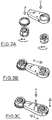
- the wheel hub is secured to the alloy wheel rim 2 by the stud 3 and its associated wheel nut 6.
- the stud 3 has helical threads that cooperate with corresponding threads on the internal surface of nut 6.
- the connector 10 links one wheel nut 6 to another preventing both nuts from loosening over time and potentially falling off when the truck is in transit.
- the connector 10 consists of a base plate 11 with a pair of cups 12 having holes 13 to fit over the wheel studs 3.
- the nuts 6 are fastened to the studs 3 and the locking caps 15 are placed over the nuts.
- the lower rim 16 of the cap 15 incorporates gear teeth to engage corresponding grooves 14 in the base of each cup 12.
- the upper rim 17 of each cap 15 is serrated to engage the corners of the hexagonal nut 6 so that the caps prevent rotation of the nuts 6.
- the central portion of the connector 10 between cups 12 is a spring loaded locking mechanism 18, to prevent removal of the caps 15.
- a key 19 is used to unlock the mechanism 18 and allow removal of the caps 15.
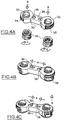
- the connector 10 is essentially in two parts.
- One part consists of a gear ring 21 which seats over one nut 6 and the other is a locking part 22 with teeth 23 at one end and a ring 24 with serrated edges 25 to engage the corners of the adjacent hexagonal nut 6 to prevent rotation of the nut 6.
- the nuts 6 are locked by placing the locking part 22 over the fastened nuts and allowing the spring loaded mechanism 28 to lock onto the nut 6.
- the nuts may be customised to interact with the lock 28. As shown in fig 3 C a key 19 is used to unlock the mechanism 28 and allow removal of the caps locking part 22.
- the connector 30 consists of a central portion with a pair of annular covers 32 having holes 33 to fit over the wheel studs 3.
- the custom nuts 36 are fastened to the studs 3 and the covers 32 of connector 30 are placed over the nuts 36.
- the outer rim 35 of the covers 32 incorporates gear teeth to be engaged by the spring loaded locking mechanism 38.
- the internal surface of each cover 32 is serrated to engage the corners of the hexagonal nut 36 to prevent rotation of the nuts 36.
- the central portion of the connector 30 between covers 32 is a spring loaded locking mechanism 38. As shown in fig 4 C compression of the spring loaded tabs 39 unlocks the mechanism 38 and allow removal of the connector 30.
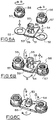
- the connector 40 consists of a base plate 41 with a pair of annular rings 42 to fit over the wheel studs 3.
- the custom nuts 46 have gear teeth 47 on their lower edges.
- Locking part 44 is clipped onto the boss 43 in the centre of base plate 41.
- Boss 43 incorporate a retaining clip 45 which can be turned to lock the part 44 to base plate 41.
- the locking part 44 includes a ring 48 with an internal serrated edge to engage the corners of the hexagonal nut 46 to prevent rotation of the nuts 46.
- the other end 49 of part 44 has teeth to engage the gear teeth 47 of the adjacent nut 46.
- the connector 50 consists of a base plate 51 with a pair of annular rings 52 to fit over the wheel studs 3.
- the custom nuts 56 have gear teeth 57 on their lower external edges.
- Locking part 54 is clipped onto the boss 53 in the centre of base plate 51.
- Boss 53 incorporates a retaining clip 55 which can be turned to lock the part 54 to base plate 51.
- the locking part 54 includes convex edge 58 with gear teeth and a concave edge 59 to engage the gear teeth 5 7 of the custom nuts 56.
- the locking part 54 engages both nuts 56 the retaining clip 55 is turned to lock the part 54 to base plate 51.
- To unlock the clip 55 is raised the locking part 54 is lifted clear and the nuts 56 can be removed.
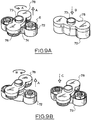
- Figure seven illustrates a sixth arrangement in which the connector is in a minimum of two parts and each part is identical and associated with one custom nut.
- the connectors may link all the nuts as shown in figure 7D .
- Each connector part 62 has concave edges 63 bearing gear teeth that engage wit the corresponding edges 63 of adjacent connectors.
- the central aperture 64 of part 62 is internally shaped to locate on the corners of the custom nut 66 which includes a recess 67 on each corner.
- An allen key turnable nut 68 engages the recesses 67 in the custom nut 66 to prevent removal of the part 62.
- the locking of the part 62 exposes a lock status indicator 69 which is green when locked and red when the part 62 is able to be removed.
- Figures 8 and 9 illustrate a seventh arrangement in which the connector 70 has a location part 71 with a pair of annular cylinders 72, to fit over the wheel studs 3.
- the annular cylinders 72 have vertical arrayed splines on its internal surface. Conventional nuts 6 may be used.
- Locking part 74 is secured by the spring tensioned pivot axis 73 in the centre of location part 71.
- the locking part 74 includes a pair of caps 78 with an internal grooved surface to engage the splines of cylinders 72 and cover the nuts 6.
- the locating part 71 is placed over two adjacent nuts and the locking part 74 is rotated so that the caps 78 are over the nuts 6.
- the spring mechanism closes the part 74 onto part 71. To unlock the part 74 is raised and rotated 90degrees as shown in figure 9 B .
- the connector 80 consists of a base plate 81 with a pair of cups 82 having holes 83 to fit over the wheel studs 3.
- the nuts 6 are fastened to the studs 3 and the locking part 85 is placed over the nuts.
- the central portion of the locking part 85 includes a spring loaded locking mechanism 88 to prevent removal of the locking part 85.
- a key 89 is used to unlock the mechanism 88 and allow removal of the locking part 85.
- the tongue 87 is rotated to cover the lock and prevent ingress of dirt.
- To remove the locking part 85 the tongue is rotated to expose the lock 88 which is unlocked with the key 89 so that locking part 85 can be removed to allow the nuts 6 to be removed.
- the connector 90 consists of a base plate 91 in two parts each having cups 92 with holes 93 to fit over the wheel studs 3.
- the two parts of plate 91 are connectable at location part 94 to accommodate for varying distances between the studs on the wheel rim.
- the nuts 6 are fastened to the studs 3 and the locking part 95 is placed over the nuts.
- the central portion of the locking part 95 includes a spring loaded locking mechanism 98 to prevent removal of the locking part 95 from the base plate 91.
- the locking part 95 includes a ring 97 with an internal serrated edge to engage the corners of the hexagonal nut 6 to prevent rotation of the nuts 6.
- a key 99 is used to unlock the mechanism 98 and allow removal of the locking part 95.
- the feature of this arrangement is the adjustability of the length of parts 91 and 95.
- the connector 100 consists of a base plate 101 having 2 annular rings 102 to fit over the wheel studs 3.
- the central portion 104 of plate 101 is adapted to receive the locking mechanism.
- the nuts 6 are fastened to the studs 3 and the locking part 105 and the associated rings 106 A B and C and D are placed over the nuts.
- the rings 106 A B and C include leaf springs 107 to cooperate with the lock actuator 108 to form a spring loaded locking mechanism.
- the rings 106 A B and C are provided with an internal serrated edge to engage the corners of the hexagonal nut 6 to prevent rotation of the nuts 6.
- the three rings 106 self align about the nut 6 and variations are compensated for by the leaf springs 107.
- a key 109 is used to unlock the mechanism 108 and allow removal of the locking part 105.
- the connector 110 consists of a base plate 111 having 2 annular rings 1 12 to fit over the wheel studs 3.
- the central portion 114 of plate 1 11 is adapted to receive the locking actuator 118.
- the custom nuts 116 incorporate ratchet teeth 1 17 on their lower edges.
- the locking part 115 includes a locking actuator 118 and associated pawls 113 that engage the ratchet teeth 117, to form a locking mechanism.
- the custom nuts 116 are fastened to the studs 3 after the locking part 115 has been placed on the base plate 111.
- a key 119 is used to turn the actuator 118, disengage the pawls from the ratchet teeth and allow removal of the locking part 115.
- Figure 16 illustrates a twelfth arrangement in which the connector 120 is attached via its central portion 121 to a stud 124 on the custom wheel rim 2.
- the connector 120 has a pair of annular cylindrical caps 122 to fit over the wheel nuts 6.
- the annular cylinders 122 have vertical arrayed splines on its internal surface. Conventional nuts 6 may be used.
- the nuts 6 are fastened to the studs 3 while the connector is aligned at right angles to the axis between the studs 3.
- the connector is lifted and turned so that the caps 122 are over the nuts 6.
- the spring loaded mechanism in the central portion 121 closes the connector 120 onto the wheel nuts. To access the wheel nuts 6 the connector 120 is raised and rotated 90 degrees.
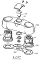
- the connector consists of a base plate 131 with a pair of holes 132 to fit over the wheel studs 3.
- the nuts 6 and spacer 133 are fastened to the studs 3 and the locking part 135, 137 is placed over the nuts so that each cylindrical end portion 135 seats over each nut 6.
- the internal lower rim 136 of the end portions 135 prevents movement of the hexagonal nut 6 along the shaft of the stud 3.
- the central portion 137 of the connector incorporates a locking mechanism 138 to prevent removal of the connector.
Landscapes
- Engineering & Computer Science (AREA)
- Mechanical Engineering (AREA)
- General Engineering & Computer Science (AREA)
- Snaps, Bayonet Connections, Set Pins, And Snap Rings (AREA)
- Connection Of Plates (AREA)
- Details Of Connecting Devices For Male And Female Coupling (AREA)
Claims (5)
- Kombination aus Radmutter und Verbinder zur Verwendung bei einer Radfelge (2) mit einer Mehrzahl von Stehbolzen (3), die Außengewinde haben, um Befestigungsmuttern aufzunehmen, wobei die Kombination enthält:eine Mehrzahl von hexagonalen Radmuttern (6), von denen jede mit einem Innengewinde versehen ist, das ausgelegt ist, um an den Stehbolzen (3) befestigt zu werden; undeinen Verbinder, der zum Anbringen und Verbinden benachbarter Muttern ausgelegt ist;wobei der Verbinder einen Mechanismus enthält, um eine Drehung der Radmuttern (6) zu verhindern, wobei der Verbinder eine Basisplatte (131) und ein Verriegelungsteil (135, 137) hat, wobei die Basisplatte (131) ein Paar von Löchern (132) hat, die über zwei der Stehbolzen (3) passen,dadurch gekennzeichnet, dass zwei der Radmuttern (6) und entsprechende Abstandhalter (133) an den Stehbolzen (3) befestigt werden, das Verriegelungsteil (135, 137) zwei zylindrische Endteile (135) hat, die jeweils interne untere Ränder (136) haben, das Verriegelungsteil (135, 137) über den zwei Radmuttern (6) angeordnet wird, so dass die internen unteren Ränder (136) der zylindrischen Endteile (135) über jeder Radmutter (6) sitzen und eine Bewegung der Radmuttern (6) längst der Stangen der Stehbolzen (3) verhindern, und ein Zentralteil (137) des Verbinder einen Verriegelungsmechanismus (138) hat, um ein Entfernen des Verbinders zu verhindern.
- Kombination nach Anspruch 1, wobei der Verriegelungsmechanismus (138) in die Basisplatte (131) und das Verriegelungsteil (137) (137) eingreift, um das Entfernen des Verbinders zu verhindern.
- Kombination nach Anspruch 1 oder 2, wobei das Verriegelungsteil (137) eine zentrale zylindrische Öffnung hat, die dadurch hindurch den Verriegelungsmechanismus (138) aufnimmt.
- Kombination nach Anspruch 1, 2 oder 3, wobei der Verbinder ferner eine Kappe enthält, die in eine Vertiefung an einer Oberseitenoberfläche des Verriegelungsteils (137) eingreift und den Verriegelungsmechanismus (138) entfernbar bedeckt.
- Kombination nach einem der Ansprüche 1 bis 4, wobei der Verriegelungsmechanismus (138) den Verbinder mit einem Schlüssel am Ort verriegelt.
Applications Claiming Priority (2)
| Application Number | Priority Date | Filing Date | Title |
|---|---|---|---|
| AU2014904801A AU2014904801A0 (en) | 2014-11-27 | Wheel retention system | |
| PCT/AU2015/000721 WO2016081985A1 (en) | 2014-11-27 | 2015-11-27 | Wheel retention system |
Publications (3)
| Publication Number | Publication Date |
|---|---|
| EP3224491A1 EP3224491A1 (de) | 2017-10-04 |
| EP3224491A4 EP3224491A4 (de) | 2018-08-08 |
| EP3224491B1 true EP3224491B1 (de) | 2022-01-05 |
Family
ID=56073214
Family Applications (1)
| Application Number | Title | Priority Date | Filing Date |
|---|---|---|---|
| EP15862539.2A Active EP3224491B1 (de) | 2014-11-27 | 2015-11-27 | Radrückhaltesystem |
Country Status (6)
| Country | Link |
|---|---|
| US (1) | US20170326910A1 (de) |
| EP (1) | EP3224491B1 (de) |
| CN (1) | CN107002739A (de) |
| AU (1) | AU2015354391B2 (de) |
| BR (1) | BR112017011132B1 (de) |
| WO (1) | WO2016081985A1 (de) |
Families Citing this family (12)
| Publication number | Priority date | Publication date | Assignee | Title |
|---|---|---|---|---|
| EP3501904B1 (de) * | 2017-12-19 | 2020-10-14 | Thule Sweden AB | Lastträgerfuss |
| CN110397657B (zh) * | 2018-04-24 | 2024-10-15 | 福建省晋江市励精汽配有限公司 | 螺母防松装置、紧固装置和车轮 |
| EP3623649A1 (de) * | 2018-09-14 | 2020-03-18 | Ruspa Officine S.P.A. | Losdrehschutz- und abdecksystem für köpfe von schrauben zur befestigung einer felge des rads eines nutzfahrzeugs |
| CN109372877A (zh) * | 2018-11-22 | 2019-02-22 | 福建省晋江市励精汽配有限公司 | 紧固件防松装置、盘式防松装置、紧固装置和车轮 |
| GB2588018A (en) * | 2018-12-03 | 2021-04-14 | Airbus Operations Ltd | Fastener locking |
| GB2579555A (en) * | 2018-12-03 | 2020-07-01 | Airbus Operations Ltd | Fastener locking |
| EP3747667B1 (de) | 2019-06-06 | 2021-08-04 | Ruspa Officine S.P.A. | Schraubenlöseschutzabdecksystem für köpfe von bolzen zur sicherung einer radfelge eines nutzfahrzeugs |
| CN111413537A (zh) * | 2020-05-11 | 2020-07-14 | 王艳军 | 一种具有防松脱机构的便携式电压检测传感器 |
| EP3909784B1 (de) * | 2020-05-13 | 2024-02-21 | Stellantis Europe S.p.A. | Kraftfahrzeugrad zusammenbau mit einer sicherungsvorrichtung |
| CA3119016A1 (en) * | 2020-05-19 | 2021-11-19 | Ifor C. Davies | Thermochromic wheel lug nut device |
| WO2022253419A1 (fr) * | 2021-06-01 | 2022-12-08 | Jacques Berger | Dispositif anti-desserrage notamment pour ecrous de roues de vehicules |
| WO2023086369A1 (en) * | 2021-11-09 | 2023-05-19 | Atlas Tube Connections, Llc | Multiple fastener restrainer and methods implementing the same |
Family Cites Families (16)
| Publication number | Priority date | Publication date | Assignee | Title |
|---|---|---|---|---|
| US1741077A (en) * | 1927-03-18 | 1929-12-24 | Rusack Herman | Nut lock |
| SE436334B (sv) * | 1981-12-14 | 1984-12-03 | Rolf Olsson | Las-eller sekerhetsanordning for bultforband |
| GB2352012B (en) * | 1999-07-16 | 2003-02-12 | Michael Robert Predeth | Wheel nut locking device |
| CA2354799A1 (en) * | 2000-08-03 | 2002-02-03 | Louis J. Illes | Wheel nut indicator assembly for vehicle wheels |
| US6682151B1 (en) * | 2002-09-24 | 2004-01-27 | Lacks Industries, Inc. | Wheel cover retention apparatus |
| GB2394265A (en) * | 2002-10-19 | 2004-04-21 | Ray Mason | Wheel Safety Device |
| WO2004042243A1 (en) * | 2002-11-06 | 2004-05-21 | Anthony Eric Welsby | Apparatus for locking screw-threaded fixing devices |
| GB2408783A (en) * | 2003-12-03 | 2005-06-08 | Charles Robert Massie | Vehicle wheel locking assembly |
| US7059684B1 (en) * | 2004-03-17 | 2006-06-13 | Polka John G | Attachment for retaining a cover to the wheel of a truck |
| FI117550B (fi) * | 2004-12-08 | 2006-11-30 | Sandvik Tamrock Oy | Menetelmä ja sovitelma pyörän käsittelyn turvallisuuden lisäämiseksi |
| GB0524928D0 (en) * | 2005-12-07 | 2006-01-18 | Rolls Royce Plc | Anti-score plates |
| US7927049B2 (en) * | 2007-08-27 | 2011-04-19 | Adams James C | Wheel lug nut management device |
| US8337129B2 (en) * | 2010-04-09 | 2012-12-25 | Bruce Richard Boyce | Wheel nut lock |
| CA2734659C (en) * | 2011-03-22 | 2018-05-01 | Centrabalance Canada Inc. | Lug nut locking device |
| US8888427B2 (en) * | 2012-07-26 | 2014-11-18 | Cnh Industrial America Llc | System for preventing rotation of fasteners |
| CN202900948U (zh) * | 2012-10-31 | 2013-04-24 | 浙江吉利汽车研究院有限公司杭州分公司 | 一种汽车车轮螺母夹 |
-
2015
- 2015-11-27 AU AU2015354391A patent/AU2015354391B2/en active Active
- 2015-11-27 BR BR112017011132-2A patent/BR112017011132B1/pt active IP Right Grant
- 2015-11-27 WO PCT/AU2015/000721 patent/WO2016081985A1/en not_active Ceased
- 2015-11-27 CN CN201580066173.6A patent/CN107002739A/zh active Pending
- 2015-11-27 EP EP15862539.2A patent/EP3224491B1/de active Active
- 2015-11-27 US US15/531,196 patent/US20170326910A1/en not_active Abandoned
Also Published As
| Publication number | Publication date |
|---|---|
| EP3224491A4 (de) | 2018-08-08 |
| US20170326910A1 (en) | 2017-11-16 |
| AU2015354391B2 (en) | 2019-05-23 |
| WO2016081985A1 (en) | 2016-06-02 |
| BR112017011132A2 (pt) | 2018-01-23 |
| CN107002739A (zh) | 2017-08-01 |
| BR112017011132B1 (pt) | 2022-01-18 |
| EP3224491A1 (de) | 2017-10-04 |
| AU2015354391A1 (en) | 2017-06-08 |
Similar Documents
| Publication | Publication Date | Title |
|---|---|---|
| EP3224491B1 (de) | Radrückhaltesystem | |
| US6053681A (en) | Wheel nut locking assembly | |
| US7927049B2 (en) | Wheel lug nut management device | |
| US7922258B2 (en) | System for attaching a wheel to a motor vehicle | |
| US9057396B2 (en) | Lug nut locking device | |
| US20110097174A1 (en) | Locking axle nut | |
| US20090167074A1 (en) | Safety device for a vehicle wheel | |
| US20140077582A1 (en) | Wheel security lock | |
| US20130126530A1 (en) | Locking Lid Container | |
| US20120280551A1 (en) | Easy-to-assemble/recycle armrest | |
| US20170144478A1 (en) | Attachment structure for visible wheel features | |
| US8393839B2 (en) | Self-locking screw connection | |
| US20180072094A1 (en) | Wheel cover of aluminum alloy wheel | |
| US20150354620A1 (en) | Tamper-Resistant Bicycle Axle Nut | |
| JP2022519406A (ja) | 中央拡張器を含むホイールロック | |
| CA2734659C (en) | Lug nut locking device | |
| EP3056748B1 (de) | Als mutter oder schraube hergestellte verriegelungsvorrichtung | |
| WO2000079140A1 (en) | Wheel nut locking assembly | |
| EP3359395B1 (de) | Sicherungsvorrichtung für ein fahrzeugrad | |
| EP3224490B1 (de) | Radmutternanordnung | |
| US10344504B2 (en) | Lug nut locking systems | |
| JP3176207U (ja) | ねじ部材及びソケットレンチ | |
| US20040007101A1 (en) | Anti-theft device and wrench tool for detaching the same | |
| US8777041B1 (en) | Locking lid container | |
| EP3747667B1 (de) | Schraubenlöseschutzabdecksystem für köpfe von bolzen zur sicherung einer radfelge eines nutzfahrzeugs |
Legal Events
| Date | Code | Title | Description |
|---|---|---|---|
| STAA | Information on the status of an ep patent application or granted ep patent |
Free format text: STATUS: THE INTERNATIONAL PUBLICATION HAS BEEN MADE |
|
| PUAI | Public reference made under article 153(3) epc to a published international application that has entered the european phase |
Free format text: ORIGINAL CODE: 0009012 |
|
| STAA | Information on the status of an ep patent application or granted ep patent |
Free format text: STATUS: REQUEST FOR EXAMINATION WAS MADE |
|
| 17P | Request for examination filed |
Effective date: 20170623 |
|
| AK | Designated contracting states |
Kind code of ref document: A1 Designated state(s): AL AT BE BG CH CY CZ DE DK EE ES FI FR GB GR HR HU IE IS IT LI LT LU LV MC MK MT NL NO PL PT RO RS SE SI SK SM TR |
|
| AX | Request for extension of the european patent |
Extension state: BA ME |
|
| DAV | Request for validation of the european patent (deleted) | ||
| DAX | Request for extension of the european patent (deleted) | ||
| A4 | Supplementary search report drawn up and despatched |
Effective date: 20180710 |
|
| RIC1 | Information provided on ipc code assigned before grant |
Ipc: B60B 3/16 20060101ALI20180704BHEP Ipc: F16B 39/10 20060101AFI20180704BHEP |
|
| GRAP | Despatch of communication of intention to grant a patent |
Free format text: ORIGINAL CODE: EPIDOSNIGR1 |
|
| STAA | Information on the status of an ep patent application or granted ep patent |
Free format text: STATUS: GRANT OF PATENT IS INTENDED |
|
| INTG | Intention to grant announced |
Effective date: 20210114 |
|
| GRAJ | Information related to disapproval of communication of intention to grant by the applicant or resumption of examination proceedings by the epo deleted |
Free format text: ORIGINAL CODE: EPIDOSDIGR1 |
|
| STAA | Information on the status of an ep patent application or granted ep patent |
Free format text: STATUS: REQUEST FOR EXAMINATION WAS MADE |
|
| INTC | Intention to grant announced (deleted) | ||
| GRAS | Grant fee paid |
Free format text: ORIGINAL CODE: EPIDOSNIGR3 |
|
| STAA | Information on the status of an ep patent application or granted ep patent |
Free format text: STATUS: GRANT OF PATENT IS INTENDED |
|
| GRAP | Despatch of communication of intention to grant a patent |
Free format text: ORIGINAL CODE: EPIDOSNIGR1 |
|
| INTG | Intention to grant announced |
Effective date: 20211005 |
|
| GRAA | (expected) grant |
Free format text: ORIGINAL CODE: 0009210 |
|
| STAA | Information on the status of an ep patent application or granted ep patent |
Free format text: STATUS: THE PATENT HAS BEEN GRANTED |
|
| AK | Designated contracting states |
Kind code of ref document: B1 Designated state(s): AL AT BE BG CH CY CZ DE DK EE ES FI FR GB GR HR HU IE IS IT LI LT LU LV MC MK MT NL NO PL PT RO RS SE SI SK SM TR |
|
| REG | Reference to a national code |
Ref country code: GB Ref legal event code: FG4D |
|
| REG | Reference to a national code |
Ref country code: CH Ref legal event code: EP |
|
| REG | Reference to a national code |
Ref country code: AT Ref legal event code: REF Ref document number: 1460848 Country of ref document: AT Kind code of ref document: T Effective date: 20220115 |
|
| REG | Reference to a national code |
Ref country code: DE Ref legal event code: R096 Ref document number: 602015076328 Country of ref document: DE |
|
| REG | Reference to a national code |
Ref country code: IE Ref legal event code: FG4D |
|
| REG | Reference to a national code |
Ref country code: LT Ref legal event code: MG9D |
|
| REG | Reference to a national code |
Ref country code: NL Ref legal event code: MP Effective date: 20220105 |
|
| REG | Reference to a national code |
Ref country code: AT Ref legal event code: MK05 Ref document number: 1460848 Country of ref document: AT Kind code of ref document: T Effective date: 20220105 |
|
| PG25 | Lapsed in a contracting state [announced via postgrant information from national office to epo] |
Ref country code: NL Free format text: LAPSE BECAUSE OF FAILURE TO SUBMIT A TRANSLATION OF THE DESCRIPTION OR TO PAY THE FEE WITHIN THE PRESCRIBED TIME-LIMIT Effective date: 20220105 |
|
| PG25 | Lapsed in a contracting state [announced via postgrant information from national office to epo] |
Ref country code: SE Free format text: LAPSE BECAUSE OF FAILURE TO SUBMIT A TRANSLATION OF THE DESCRIPTION OR TO PAY THE FEE WITHIN THE PRESCRIBED TIME-LIMIT Effective date: 20220105 Ref country code: RS Free format text: LAPSE BECAUSE OF FAILURE TO SUBMIT A TRANSLATION OF THE DESCRIPTION OR TO PAY THE FEE WITHIN THE PRESCRIBED TIME-LIMIT Effective date: 20220105 Ref country code: PT Free format text: LAPSE BECAUSE OF FAILURE TO SUBMIT A TRANSLATION OF THE DESCRIPTION OR TO PAY THE FEE WITHIN THE PRESCRIBED TIME-LIMIT Effective date: 20220505 Ref country code: NO Free format text: LAPSE BECAUSE OF FAILURE TO SUBMIT A TRANSLATION OF THE DESCRIPTION OR TO PAY THE FEE WITHIN THE PRESCRIBED TIME-LIMIT Effective date: 20220405 Ref country code: LT Free format text: LAPSE BECAUSE OF FAILURE TO SUBMIT A TRANSLATION OF THE DESCRIPTION OR TO PAY THE FEE WITHIN THE PRESCRIBED TIME-LIMIT Effective date: 20220105 Ref country code: HR Free format text: LAPSE BECAUSE OF FAILURE TO SUBMIT A TRANSLATION OF THE DESCRIPTION OR TO PAY THE FEE WITHIN THE PRESCRIBED TIME-LIMIT Effective date: 20220105 Ref country code: ES Free format text: LAPSE BECAUSE OF FAILURE TO SUBMIT A TRANSLATION OF THE DESCRIPTION OR TO PAY THE FEE WITHIN THE PRESCRIBED TIME-LIMIT Effective date: 20220105 Ref country code: BG Free format text: LAPSE BECAUSE OF FAILURE TO SUBMIT A TRANSLATION OF THE DESCRIPTION OR TO PAY THE FEE WITHIN THE PRESCRIBED TIME-LIMIT Effective date: 20220405 |
|
| PG25 | Lapsed in a contracting state [announced via postgrant information from national office to epo] |
Ref country code: PL Free format text: LAPSE BECAUSE OF FAILURE TO SUBMIT A TRANSLATION OF THE DESCRIPTION OR TO PAY THE FEE WITHIN THE PRESCRIBED TIME-LIMIT Effective date: 20220105 Ref country code: LV Free format text: LAPSE BECAUSE OF FAILURE TO SUBMIT A TRANSLATION OF THE DESCRIPTION OR TO PAY THE FEE WITHIN THE PRESCRIBED TIME-LIMIT Effective date: 20220105 Ref country code: GR Free format text: LAPSE BECAUSE OF FAILURE TO SUBMIT A TRANSLATION OF THE DESCRIPTION OR TO PAY THE FEE WITHIN THE PRESCRIBED TIME-LIMIT Effective date: 20220406 Ref country code: FI Free format text: LAPSE BECAUSE OF FAILURE TO SUBMIT A TRANSLATION OF THE DESCRIPTION OR TO PAY THE FEE WITHIN THE PRESCRIBED TIME-LIMIT Effective date: 20220105 Ref country code: AT Free format text: LAPSE BECAUSE OF FAILURE TO SUBMIT A TRANSLATION OF THE DESCRIPTION OR TO PAY THE FEE WITHIN THE PRESCRIBED TIME-LIMIT Effective date: 20220105 |
|
| PG25 | Lapsed in a contracting state [announced via postgrant information from national office to epo] |
Ref country code: IS Free format text: LAPSE BECAUSE OF FAILURE TO SUBMIT A TRANSLATION OF THE DESCRIPTION OR TO PAY THE FEE WITHIN THE PRESCRIBED TIME-LIMIT Effective date: 20220505 |
|
| REG | Reference to a national code |
Ref country code: DE Ref legal event code: R097 Ref document number: 602015076328 Country of ref document: DE |
|
| PG25 | Lapsed in a contracting state [announced via postgrant information from national office to epo] |
Ref country code: SM Free format text: LAPSE BECAUSE OF FAILURE TO SUBMIT A TRANSLATION OF THE DESCRIPTION OR TO PAY THE FEE WITHIN THE PRESCRIBED TIME-LIMIT Effective date: 20220105 Ref country code: SK Free format text: LAPSE BECAUSE OF FAILURE TO SUBMIT A TRANSLATION OF THE DESCRIPTION OR TO PAY THE FEE WITHIN THE PRESCRIBED TIME-LIMIT Effective date: 20220105 Ref country code: RO Free format text: LAPSE BECAUSE OF FAILURE TO SUBMIT A TRANSLATION OF THE DESCRIPTION OR TO PAY THE FEE WITHIN THE PRESCRIBED TIME-LIMIT Effective date: 20220105 Ref country code: EE Free format text: LAPSE BECAUSE OF FAILURE TO SUBMIT A TRANSLATION OF THE DESCRIPTION OR TO PAY THE FEE WITHIN THE PRESCRIBED TIME-LIMIT Effective date: 20220105 Ref country code: DK Free format text: LAPSE BECAUSE OF FAILURE TO SUBMIT A TRANSLATION OF THE DESCRIPTION OR TO PAY THE FEE WITHIN THE PRESCRIBED TIME-LIMIT Effective date: 20220105 Ref country code: CZ Free format text: LAPSE BECAUSE OF FAILURE TO SUBMIT A TRANSLATION OF THE DESCRIPTION OR TO PAY THE FEE WITHIN THE PRESCRIBED TIME-LIMIT Effective date: 20220105 |
|
| PLBE | No opposition filed within time limit |
Free format text: ORIGINAL CODE: 0009261 |
|
| STAA | Information on the status of an ep patent application or granted ep patent |
Free format text: STATUS: NO OPPOSITION FILED WITHIN TIME LIMIT |
|
| PG25 | Lapsed in a contracting state [announced via postgrant information from national office to epo] |
Ref country code: AL Free format text: LAPSE BECAUSE OF FAILURE TO SUBMIT A TRANSLATION OF THE DESCRIPTION OR TO PAY THE FEE WITHIN THE PRESCRIBED TIME-LIMIT Effective date: 20220105 |
|
| 26N | No opposition filed |
Effective date: 20221006 |
|
| PG25 | Lapsed in a contracting state [announced via postgrant information from national office to epo] |
Ref country code: SI Free format text: LAPSE BECAUSE OF FAILURE TO SUBMIT A TRANSLATION OF THE DESCRIPTION OR TO PAY THE FEE WITHIN THE PRESCRIBED TIME-LIMIT Effective date: 20220105 |
|
| PG25 | Lapsed in a contracting state [announced via postgrant information from national office to epo] |
Ref country code: MC Free format text: LAPSE BECAUSE OF FAILURE TO SUBMIT A TRANSLATION OF THE DESCRIPTION OR TO PAY THE FEE WITHIN THE PRESCRIBED TIME-LIMIT Effective date: 20220105 |
|
| REG | Reference to a national code |
Ref country code: CH Ref legal event code: PL |
|
| REG | Reference to a national code |
Ref country code: BE Ref legal event code: MM Effective date: 20221130 |
|
| PG25 | Lapsed in a contracting state [announced via postgrant information from national office to epo] |
Ref country code: LI Free format text: LAPSE BECAUSE OF NON-PAYMENT OF DUE FEES Effective date: 20221130 Ref country code: CH Free format text: LAPSE BECAUSE OF NON-PAYMENT OF DUE FEES Effective date: 20221130 |
|
| PG25 | Lapsed in a contracting state [announced via postgrant information from national office to epo] |
Ref country code: LU Free format text: LAPSE BECAUSE OF NON-PAYMENT OF DUE FEES Effective date: 20221127 |
|
| PG25 | Lapsed in a contracting state [announced via postgrant information from national office to epo] |
Ref country code: IE Free format text: LAPSE BECAUSE OF NON-PAYMENT OF DUE FEES Effective date: 20221127 |
|
| PG25 | Lapsed in a contracting state [announced via postgrant information from national office to epo] |
Ref country code: FR Free format text: LAPSE BECAUSE OF NON-PAYMENT OF DUE FEES Effective date: 20221130 Ref country code: BE Free format text: LAPSE BECAUSE OF NON-PAYMENT OF DUE FEES Effective date: 20221130 |
|
| PG25 | Lapsed in a contracting state [announced via postgrant information from national office to epo] |
Ref country code: HU Free format text: LAPSE BECAUSE OF FAILURE TO SUBMIT A TRANSLATION OF THE DESCRIPTION OR TO PAY THE FEE WITHIN THE PRESCRIBED TIME-LIMIT; INVALID AB INITIO Effective date: 20151127 |
|
| PG25 | Lapsed in a contracting state [announced via postgrant information from national office to epo] |
Ref country code: CY Free format text: LAPSE BECAUSE OF FAILURE TO SUBMIT A TRANSLATION OF THE DESCRIPTION OR TO PAY THE FEE WITHIN THE PRESCRIBED TIME-LIMIT Effective date: 20220105 |
|
| PG25 | Lapsed in a contracting state [announced via postgrant information from national office to epo] |
Ref country code: MK Free format text: LAPSE BECAUSE OF FAILURE TO SUBMIT A TRANSLATION OF THE DESCRIPTION OR TO PAY THE FEE WITHIN THE PRESCRIBED TIME-LIMIT Effective date: 20220105 |
|
| PG25 | Lapsed in a contracting state [announced via postgrant information from national office to epo] |
Ref country code: TR Free format text: LAPSE BECAUSE OF FAILURE TO SUBMIT A TRANSLATION OF THE DESCRIPTION OR TO PAY THE FEE WITHIN THE PRESCRIBED TIME-LIMIT Effective date: 20220105 |
|
| PG25 | Lapsed in a contracting state [announced via postgrant information from national office to epo] |
Ref country code: MT Free format text: LAPSE BECAUSE OF FAILURE TO SUBMIT A TRANSLATION OF THE DESCRIPTION OR TO PAY THE FEE WITHIN THE PRESCRIBED TIME-LIMIT Effective date: 20220105 |
|
| PGFP | Annual fee paid to national office [announced via postgrant information from national office to epo] |
Ref country code: GB Payment date: 20241226 Year of fee payment: 10 |
|
| PGFP | Annual fee paid to national office [announced via postgrant information from national office to epo] |
Ref country code: IT Payment date: 20241129 Year of fee payment: 10 |
|
| PGFP | Annual fee paid to national office [announced via postgrant information from national office to epo] |
Ref country code: DE Payment date: 20251128 Year of fee payment: 11 |