EP3224703B1 - Elektronische vorrichtung und verfahren zur anzeige von grafikobjekten davon - Google Patents
Elektronische vorrichtung und verfahren zur anzeige von grafikobjekten davon Download PDFInfo
- Publication number
- EP3224703B1 EP3224703B1 EP15863317.2A EP15863317A EP3224703B1 EP 3224703 B1 EP3224703 B1 EP 3224703B1 EP 15863317 A EP15863317 A EP 15863317A EP 3224703 B1 EP3224703 B1 EP 3224703B1
- Authority
- EP
- European Patent Office
- Prior art keywords
- display
- touch pen
- graphical object
- input
- controller
- Prior art date
- Legal status (The legal status is an assumption and is not a legal conclusion. Google has not performed a legal analysis and makes no representation as to the accuracy of the status listed.)
- Not-in-force
Links
Images









Classifications
-
- G—PHYSICS
- G06—COMPUTING OR CALCULATING; COUNTING
- G06F—ELECTRIC DIGITAL DATA PROCESSING
- G06F3/00—Input arrangements for transferring data to be processed into a form capable of being handled by the computer; Output arrangements for transferring data from processing unit to output unit, e.g. interface arrangements
- G06F3/01—Input arrangements or combined input and output arrangements for interaction between user and computer
- G06F3/048—Interaction techniques based on graphical user interfaces [GUI]
-
- G—PHYSICS
- G06—COMPUTING OR CALCULATING; COUNTING
- G06F—ELECTRIC DIGITAL DATA PROCESSING
- G06F3/00—Input arrangements for transferring data to be processed into a form capable of being handled by the computer; Output arrangements for transferring data from processing unit to output unit, e.g. interface arrangements
- G06F3/01—Input arrangements or combined input and output arrangements for interaction between user and computer
- G06F3/03—Arrangements for converting the position or the displacement of a member into a coded form
- G06F3/033—Pointing devices displaced or positioned by the user, e.g. mice, trackballs, pens or joysticks; Accessories therefor
- G06F3/038—Control and interface arrangements therefor, e.g. drivers or device-embedded control circuitry
-
- G—PHYSICS
- G06—COMPUTING OR CALCULATING; COUNTING
- G06F—ELECTRIC DIGITAL DATA PROCESSING
- G06F3/00—Input arrangements for transferring data to be processed into a form capable of being handled by the computer; Output arrangements for transferring data from processing unit to output unit, e.g. interface arrangements
- G06F3/01—Input arrangements or combined input and output arrangements for interaction between user and computer
- G06F3/03—Arrangements for converting the position or the displacement of a member into a coded form
- G06F3/033—Pointing devices displaced or positioned by the user, e.g. mice, trackballs, pens or joysticks; Accessories therefor
- G06F3/0354—Pointing devices displaced or positioned by the user, e.g. mice, trackballs, pens or joysticks; Accessories therefor with detection of two-dimensional [2D] relative movements between the device, or an operating part thereof, and a plane or surface, e.g. 2D mice, trackballs, pens or pucks
- G06F3/03545—Pens or stylus
-
- G—PHYSICS
- G06—COMPUTING OR CALCULATING; COUNTING
- G06F—ELECTRIC DIGITAL DATA PROCESSING
- G06F1/00—Details not covered by groups G06F3/00 - G06F13/00 and G06F21/00
- G06F1/16—Constructional details or arrangements
- G06F1/1613—Constructional details or arrangements for portable computers
- G06F1/1633—Constructional details or arrangements of portable computers not specific to the type of enclosures covered by groups G06F1/1615 - G06F1/1626
- G06F1/1637—Details related to the display arrangement, including those related to the mounting of the display in the housing
- G06F1/1643—Details related to the display arrangement, including those related to the mounting of the display in the housing the display being associated to a digitizer, e.g. laptops that can be used as penpads
-
- G—PHYSICS
- G06—COMPUTING OR CALCULATING; COUNTING
- G06F—ELECTRIC DIGITAL DATA PROCESSING
- G06F3/00—Input arrangements for transferring data to be processed into a form capable of being handled by the computer; Output arrangements for transferring data from processing unit to output unit, e.g. interface arrangements
- G06F3/01—Input arrangements or combined input and output arrangements for interaction between user and computer
- G06F3/03—Arrangements for converting the position or the displacement of a member into a coded form
- G06F3/033—Pointing devices displaced or positioned by the user, e.g. mice, trackballs, pens or joysticks; Accessories therefor
-
- G—PHYSICS
- G06—COMPUTING OR CALCULATING; COUNTING
- G06F—ELECTRIC DIGITAL DATA PROCESSING
- G06F3/00—Input arrangements for transferring data to be processed into a form capable of being handled by the computer; Output arrangements for transferring data from processing unit to output unit, e.g. interface arrangements
- G06F3/01—Input arrangements or combined input and output arrangements for interaction between user and computer
- G06F3/048—Interaction techniques based on graphical user interfaces [GUI]
- G06F3/0484—Interaction techniques based on graphical user interfaces [GUI] for the control of specific functions or operations, e.g. selecting or manipulating an object, an image or a displayed text element, setting a parameter value or selecting a range
- G06F3/04845—Interaction techniques based on graphical user interfaces [GUI] for the control of specific functions or operations, e.g. selecting or manipulating an object, an image or a displayed text element, setting a parameter value or selecting a range for image manipulation, e.g. dragging, rotation, expansion or change of colour
-
- G—PHYSICS
- G06—COMPUTING OR CALCULATING; COUNTING
- G06F—ELECTRIC DIGITAL DATA PROCESSING
- G06F3/00—Input arrangements for transferring data to be processed into a form capable of being handled by the computer; Output arrangements for transferring data from processing unit to output unit, e.g. interface arrangements
- G06F3/01—Input arrangements or combined input and output arrangements for interaction between user and computer
- G06F3/048—Interaction techniques based on graphical user interfaces [GUI]
- G06F3/0487—Interaction techniques based on graphical user interfaces [GUI] using specific features provided by the input device, e.g. functions controlled by the rotation of a mouse with dual sensing arrangements, or of the nature of the input device, e.g. tap gestures based on pressure sensed by a digitiser
- G06F3/0488—Interaction techniques based on graphical user interfaces [GUI] using specific features provided by the input device, e.g. functions controlled by the rotation of a mouse with dual sensing arrangements, or of the nature of the input device, e.g. tap gestures based on pressure sensed by a digitiser using a touch-screen or digitiser, e.g. input of commands through traced gestures
-
- G—PHYSICS
- G06—COMPUTING OR CALCULATING; COUNTING
- G06F—ELECTRIC DIGITAL DATA PROCESSING
- G06F3/00—Input arrangements for transferring data to be processed into a form capable of being handled by the computer; Output arrangements for transferring data from processing unit to output unit, e.g. interface arrangements
- G06F3/01—Input arrangements or combined input and output arrangements for interaction between user and computer
- G06F3/048—Interaction techniques based on graphical user interfaces [GUI]
- G06F3/0487—Interaction techniques based on graphical user interfaces [GUI] using specific features provided by the input device, e.g. functions controlled by the rotation of a mouse with dual sensing arrangements, or of the nature of the input device, e.g. tap gestures based on pressure sensed by a digitiser
- G06F3/0488—Interaction techniques based on graphical user interfaces [GUI] using specific features provided by the input device, e.g. functions controlled by the rotation of a mouse with dual sensing arrangements, or of the nature of the input device, e.g. tap gestures based on pressure sensed by a digitiser using a touch-screen or digitiser, e.g. input of commands through traced gestures
- G06F3/04883—Interaction techniques based on graphical user interfaces [GUI] using specific features provided by the input device, e.g. functions controlled by the rotation of a mouse with dual sensing arrangements, or of the nature of the input device, e.g. tap gestures based on pressure sensed by a digitiser using a touch-screen or digitiser, e.g. input of commands through traced gestures for inputting data by handwriting, e.g. gesture or text
-
- G—PHYSICS
- G06—COMPUTING OR CALCULATING; COUNTING
- G06F—ELECTRIC DIGITAL DATA PROCESSING
- G06F2200/00—Indexing scheme relating to G06F1/04 - G06F1/32
- G06F2200/16—Indexing scheme relating to G06F1/16 - G06F1/18
- G06F2200/161—Indexing scheme relating to constructional details of the monitor
- G06F2200/1614—Image rotation following screen orientation, e.g. switching from landscape to portrait mode
Definitions
- the present disclosure relates to an electronic apparatus and a method for displaying a graphical object thereof.
- an input method of the portable terminal has developed from a user interface (UI) method of the related art of using an input means, such as, a keyboard, a keypad, a mouse, etc., into an intuitional UI method of inputting information by using a voice or directly touching a screen with a hand or a touch pen for various users.
- UI user interface
- a user is able to perform more accurate touch or input a handwriting by using a touch pen.
- a direction of the handwriting may differ from a display direction of a graphical object. Accordingly, there is a desire for diverse methods for automatically arranging the direction of handwriting using a touch pen to correspond to the display direction of the graphical object.
- JP H05-250090 A discloses a pen type input tablet device comprising: a position detecting means that detects the position of a pen type instructing device by the approach or the contact of the pen type instructing device to the pen type input tablet device; an inclination detecting means that detects the inclination of the pen type instructing device to the pen type input tablet device by the approach or the contact of the pen type instructing device to the pen type input tablet device; an inputted contents judging means that judges inputted contents corresponding to the movement of the pen type instructing device on the basis of the a detected result by the position detecting means; an existence direction judging means that judges the existence direction of the operator of the pen type instructing device on the basis of the detected result by the inclination detecting means; and a display direction changing means that changes a display direction on the display screen of a display device.
- JP 2009/237836 A discloses an in-vehicle electronic equipment with: a display part having a handwriting input panel for inputting handwritten characters; and a handwriting input panel for displaying a character input frame on the display part, and for identifying and specifying characters input by handwriting in the character input frame.
- the in-vehicle electronic equipment is provided with an angle detection part for detecting an angle made by a display screen on which an operator inputs characters to the character input frame displayed on the display part and a direction in the operation by the operator, and an input frame switching part for switching the display of the character input frame to be displayed at the display part.
- the input frame switching part switches the display of the character input frame by rotating it at different angles according to the detection result of the angle detection part.
- an aspect of the present disclosure is to provide an electronic apparatus and a method for displaying a graphical object thereof, and more particularly, to a method of recognizing a handwriting direction by using an angle between a touch pen and a display and travel direction of the handwriting and automatically changing a display direction of a graphical object displayed in the display to a horizontal direction or a vertical direction based on the handwriting direction.
- an electronic apparatus is provided as defined in the appended claims.
- the electronic apparatus includes a sensor configured to sense an input of a touch pen and output a signal corresponding to the input of the touch pen, a display configured to include a first layer and a second layer, display a graphical object in the first layer, and display a handwriting image based on the input of the touch pen in the second layer, and a controller configured to control the display to change a display direction of the graphical object displayed in the first layer based on the signal output from the sensor.
- the controller may determine a tilt direction of the touch pen based on the signal output from the sensor and control the display to change the display direction of the graphical object displayed in the first layer according to the tilt direction of the touch pen.
- the controller may control the display to maintain a direction of the second layer without change despite a direction of the first layer being changed.
- the method may further include receiving a signal output from the touch pen.
- the tilt information of the touch pen may be determined based on the signal.
- the changing of the display direction of the graphical object may include determining a tilt direction of the touch pen based on tilt information of the touch pen and determining the display direction of the graphical object based on the tilt direction of the touch pen.
- the changing of the display direction of the graphical object may include changing the display direction of the graphical object so that the tilt direction of the touch pen and the display direction of the graphical object become opposite to each other.
- the method may further include displaying a handwriting image based on the input of the touch pen.
- the graphical object may be displayed in a first layer, and the handwriting image displayed based on the input of the touch pen may be displayed in a second layer.
- the changing of the display direction of the graphical object may include fixing the second layer and changing the display direction of the graphical object in the first layer based on the tilt direction of the touch pen.
- the method includes displaying a graphical object in a first layer, sensing an input of a touch pen, displaying a handwriting image in a second layer based on the input of the touch pen, and changing a display direction of the graphical object displayed in the first layer based on the input of the touch pen.
- the changing of the display direction of the graphical object may include determining a tilt direction of the touch pen based on the input of the touch pen and changing the display direction of the graphical object displayed in the first layer according to the tilt direction of the touch pen.
- the method may further include maintaining a direction of the second layer without change despite the display direction of the graphical object being changed.
- a method for displaying a graphical object of an electronic apparatus changes a display direction of a graphical object automatically based on a handwriting direction, thereby providing a user with convenience.
- the terms 'include' and 'may include' used in the following descriptions refer to the disclosed function, operation, or element and do not limit any additional one or more functions, operations, or elements.
- the terms 'include' and 'have' show existence of a feature, number, operation, element, part, or combination thereof disclosed herein and are not intended to exclude the possibilities of combination or addition of one or more features, numbers, operations, elements, parts or combination thereof.
- 'A or B' may include A, may include B, or may include both of A and B.
- relational terms such as 'first' and 'second,' may modify various elements but do not limit the elements.
- the terms are used to distinguish one entity from another entity, without necessarily implying any actual relationship or order between such entities.
- both of the first user device and the second user device refer to a user device and represent distinct user devices, respectively.
- the first element may be called the second element without deviating from the scope of right of the present disclosure, and vice versa.
- an element When it is described that an element is 'connected' to another component, the element may be connected to another element directly, but in this case, it may be understood that any other element may exist between the element and another element.
- an element When it is described that an element is 'directly connected' to another element, it may be understood that any other element does not exist between the element and another element.
- 'module' or 'unit' performs at least one function or operation and may be realized as hardware, software, or combination thereof.
- a plurality of 'modules' or 'units' may be integrated into at least one module and may be realized as at least one processor (not shown) except for 'module' or 'unit' that needs to be realized as specific hardware.
- FIG. 1 is a block diagram illustrating a structure of an electronic apparatus 100 according to an embodiment of the present disclosure.
- the electronic apparatus 100 may include a display 101, a controller 103, a sensor 105, and a communicator 107.
- the display 101 may display a graphical object and perform a display function with respect to output information output from the electronic apparatus 100.
- the graphical object may be a moving image, a still image, an electronic book (E-book) screen, a web page, a content, and a graphic user interface (GUI).
- E-book electronic book
- GUI graphic user interface
- the sensor 105 may perform various input functions by a user.
- the sensor 105 may sense diverse inputs including a single-touch input, a multi-touch input, a drag input, a handwriting input, or a drawing input of the user by using a variety of objects, such as, a finger, a pen, etc.
- the sensor 105 may be provided in a form of a module realized as a single body with the display 101.
- the sensor 105 may be realized by using one panel which is capable of sensing both of an input of a finger and an input of a touch pen 201 or may be realized by using two panels, such as, a touch panel of sensing a finger input and a touch pen recognition panel of sensing a touch pen input.
- the sensor 105 realized with two panels, the touch panel of sensing a finger input and the touch pen recognition panel of sensing a touch pen input.
- the display 101 may be a panel such as liquid crystal display (LCD), active matrix organic light emitting diodes (AMOLED), etc.
- the display 101 may display diverse screens according to various operational statuses, execution of an application, and a service of the electronic apparatus 100.
- the display 101 may include a touch panel.
- the touch panel may occupy a certain space in a lower part of the display 101. For example, the touch panel may occupy a space to cover a display area of the display 101.
- the touch panel may sense a user touch input.
- the touch panel may be realized as a touch film, a touch sheet, a touch pad, etc.
- the touch panel senses a touch input and outputs a touch event value corresponding to the sensed touch signal.
- information on the sensed touch signal may be displayed in the display 101.
- the touch panel may receive a manipulation signal according to the user touch input through various input means.
- the touch panel may sense a touch input using a user body (for example, a finger) or a physical tool.
- the touch panel may be realized as a capacitive-type touch panel.
- the touch panel consists of a glass of which both surfaces are coated with thin metal conducting material (for example, indium tin oxide (IPO)) for enabling a current to flow along the surfaces of the glass and is coated with a dielectric substance for storing a charge.
- thin metal conducting material for example, indium tin oxide (IPO)
- IP indium tin oxide
- the touch panel recognizes variation of the current according to the movement of the charge to sense a touched point and tracks a touch event.
- the touch event occurred in the touch panel may be generated by a finger of a human being in many cases but may be generated by other object which may cause change of capacitance, for example, a conductive object which may cause change of capacitance.
- the touch pen recognition panel senses an access input or touch input of the touch pen 210 using a pen for touch of the user (for example, a stylus pen, a digitizer pen, etc.) and outputs a touch pen access event or a touch pen touch event.
- the touch pen recognition panel may be realized in an electro-magnetic resonance (EMR) method.
- EMR electro-magnetic resonance
- the touch pen recognition panel may sense a touch input or an access input according to variation of strength of an electromagnetic field by the access or touch of the touch pen 201.
- the touch pen recognition panel may include an electromagnetic induction coil sensor (not shown) having a grid structure where a plurality of loop coils are respectively arranged in a predetermined first direction and a second direction which intersects the first direction and an electronic signal processor (not shown) which sequentially supplies alternating current (AC) signals having a certain frequency to the respective loop coils of the electromagnetic induction coil sensor.
- an electromagnetic induction coil sensor not shown
- an electronic signal processor not shown
- AC alternating current
- an induction magnetic field is generated from the coils constituting the resonant circuit in the touch pen 201.
- the touch pen recognition panel detects the induction magnetic field from a loop coil in a signal receiving status and senses an access position or a touch position of the touch pen 201.
- the touch pen recognition panel may sense an access or touch of an object which may generate the current based on the electromagnetic induction.
- the touch pen recognition panel is exclusively used for the recognition on the access or touch of the touch pen 201.
- the touch pen recognition panel may be installed at a certain position of a terminal and may have an activated state by occurrence of a particular event or by default.
- the touch pen recognition panel may occupy a certain space in the lower part of the display 101.
- the touch pen recognition panel may occupy a space to cover a display area of the display 101.
- the communicator 107 may receive a signal from an external source of the electronic apparatus 100. Specially, in case of the electronic apparatus 100 supporting a mobile communication function, the communicator 107 may include a mobile communication module. The communicator 107 may perform particular functions of the electronic apparatus 100 requiring a communication function, for example, a chat function, a message transmission/reception function, a call function, etc. In addition, the communicator 107 may receive a signal from an external device such as the touch pen 201. The touch pen 201 may transmit information on a tilt of the touch pen 201 to the electronic apparatus 100 through the communicator 107.
- the controller 103 includes various elements for receiving an input of the handwriting using the touch pen 201 and displaying the received handwriting.
- the controller 103 may control a signal processing operation, a data processing operation, and other functions for the handwriting input based on the elements.
- the controller 103 may provide a displayed application with a handwriting input layer and control the display 101 to convert a handwriting image input by the user into text on the provided handwriting input layer and insert and display the text into an input filed.
- the controller 103 may determine a display direction of a graphical object displayed in the display 101 based on a signal output from the sensor 105 in response to the touch pen input being input into the display 101. To be specific, the controller 103 may determine tilt information of the touch pen 201 based on the signal output from the sensor 105. The tilt information of the touch pen 201 may be an angle between the display 101 and the touch pen 201 and a tilt direction of the touch pen 201.
- the touch pen 201 may output the information on the tilt angle and the tilt direction of the touch pen 201 in a form of a signal.
- the controller 103 may receive the signal output from the touch pen 201 through the communicator 107 and determine the tilt information of the touch pen 201 based on the signal output from the touch pen 201.
- the controller 103 may determine a tilt direction of the touch pen 201 based on the tilt information of the touch pen 201 and determine the display direction of the graphical object based on the tilt direction of the touch pen 201. In addition, the controller 103 may control the display 101 to change the display direction of the graphical object so that the tilt direction of the touch pen 201 and the display direction of the graphical object become opposite to each other.
- the controller 103 may control the display 101 to display the graphical object in a first layer and display a handwriting image displayed based on the touch pen input in a second layer.
- the controller 103 may control the display 101 to fix the second layer and change the display direction of the graphical object in the first layer based on the tilt direction of the touch pen 201.
- the controller 103 may control the display 101 to change the display direction of the graphical object displayed in the first layer based on the signal output from the sensor 105. In addition, the controller 103 may determine the display direction of the graphical object displayed in the first layer based on the signal output from the sensor 105. The controller 103 may determine the tilt direction of the touch pen 201 based on the signal output from the sensor 105 and control the display 101 to change the display direction of the graphical object displayed in the first layer according to the tilt direction of the touch pen 201.
- FIGS. 2A and 2B are views provided to describe an embodiment of changing a display direction of a graphical object according to a tilt direction of the touch pen 201 according to an embodiment of the present disclosure.
- FIG. 2A illustrates the electronic apparatus 100, the display 101, and the touch pen 201.
- the controller 103 may determine a contact point of the touch pen 201 and an angle (P) 203 between the touch pen 201 and the display 101. That is, the controller 103 may determine the tilt direction of the touch pen 201.
- FIG. 2B illustrates the tilt direction of the touch pen 201 and a display direction according to the tilt direction.
- the controller 103 may determine a direction to which the touch pen 201 tilts among four directions of upward, downward, right, and left directions 211, 213, 215, 217, with reference to a center of the display 101. Subsequently, the controller 103 may determine display directions of the graphical object 219, 221, 223, 225 based on the tilt direction of the touch pen 201 and control the display 101 to rotate a screen. That is, the controller 103 may control the display 101 to change the display direction of the graphical object.
- the controller 103 may determine the display direction of the graphical object as a first direction 219 and control the display 101 to rotate the screen based on the determined display direction.
- the controller 103 may determine the display direction of the graphical object as a second direction 221 and control the display 101 to rotate the screen based on the determined display direction.
- the controller 103 may determine the display direction of the graphical object as a third direction 223 and control the display 101 to rotate the screen based on the determined display direction.
- the controller 103 may determine the display direction of the graphical object as a fourth direction 225 and control the display 101 to rotate the screen based on the determined display direction.
- the controller 103 may differently determine the display direction based on the tilt direction of the touch pen 201 according to whether a user hand holding the touch pen 201 is a left hand or a right hand. For example, in response to the touch pen 201 tilting in the 'a' direction 211 as the user brings the touch pen 201 into contact with the display 101 by a left hand, the controller 103 may determine the display direction of the graphical object as the fourth direction 225 and control the display 101 to rotate the screen based on the determined direction.
- the controller 103 may determine the display direction of the graphical object as the first direction 219 and control the display 101 to rotate the screen based on the determined direction.
- the controller 103 may determine the display direction of the graphical object as the second direction 221 and control the display 101 to rotate the screen based on the determined direction.
- the controller 103 may determine the display direction of the graphical object as the third direction 223 and control the display 101 to rotate the screen based on the determined direction.
- the controller 103 may determine the display direction of the graphical object as the first direction 219 and control the display 101 to rotate the screen based on the determined direction.
- the controller 103 may determine the display direction of the graphical object as the second direction 221 and control the display 101 to rotate the screen based on the determined direction.
- the controller 103 may determine the display direction of the graphical object as the third direction 223 and control the display 101 to rotate the screen based on the determined direction.
- the controller 103 may determine the display direction of the graphical object as the fourth direction 225 and control the display 101 to rotate the screen based on the determined direction
- the user is able to select whether to use the electronic apparatus 100 in a right-hand mode or in a left-hand mode.
- the controller 103 may determine that the user holds the touch pen 201 by the right hand and determine the display direction of the graphical object accordingly.
- the controller 103 may determine that the user holds the touch pen 201 by the left hand, determine the display direction of the graphical object accordingly, and control the display 101 to rotate the screen based on the determined direction.
- the controller 103 determines whether to use the right-hand mode or user the left-hand mode based on the angle between the touch pen 201 and the display 101 and a traveling direction of the handwriting. For example, in response to the tilt direction of the touch pen 201 being the 'b' direction 213 and the traveling direction of the handwriting being a right direction, the controller 103 determines to use the left-hand mode. In response to the tilt direction of the touch pen 201 being the 'a' direction 211 and the traveling direction of the handwriting being the right direction, the controller 103 determines to use the right-hand mode.
- controller 103 may determine whether to use the right-hand mode or use the left-hand mode based the angle between the touch pen 201 and the display 101 and the contact point of the user hand.
- the controller 103 may determine the display direction of the graphical object based on a signal output from a gravity sensor (not shown).
- a gravity sensor not shown
- the controller 103 may determine the display direction of the graphical object based on the tilt direction of the touch pen 201.
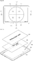
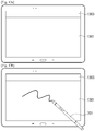
- FIGS. 3A and 3B are views illustrating a handwriting input layer and a graphical object display layer according to an embodiment of the present disclosure.
- FIG. 3A illustrates a graphical object display layer 301, a handwriting input layer 303, and the touch pen 201.
- a graphic character and image may be displayed in the graphical object display layer 301.
- an icon and button for executing a character, a content, and an application may be displayed in the graphical object display layer 301.
- a handwriting image based on the input of the touch pen 201 may be displayed in the handwriting input layer 303.
- the handwriting image may be generated in response to the user moving the touch pen 201 while maintaining the touch of the touch pen 201 with respect to the display 101.
- the generated handwriting image may be converted into text.
- the handwriting input layer 303 may be provided in a transparent form or in a translucent form, for example.
- the electronic apparatus 100 may receive the handwriting image using the touch pen 201 through the provided handwriting input layer 303.
- the received handwriting image may be displayed in the handwriting input layer 303.
- the handwriting image is displayed in the handwriting input layer 303 different from the graphical object display layer 301, and thus, the received handwriting image may be processed separately from the graphical object. That is, the controller 103 may recognize and process the handwriting image displayed in the graphical object display layer 301 as a distinct object. For example, the controller 103 may erase only the handwriting image separately.
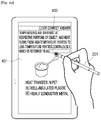
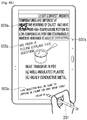
- FIG. 3B illustrates the electronic apparatus 100, graphical objects 101a, 101b, the graphical object display layer 301, the handwriting input layer 303, a handwriting image 305, and the touch pen 201.
- the graphical object 101b is the graphical object 101a which rotated 90 degrees.
- the electronic apparatus 100 may display the graphical object 101a in the display 101, sense the input of the touch pen 201, and change the display direction of the graphical object displayed in the display 101 based on the input of the touch pen 201.
- the lower drawing of FIG. 3B illustrates the changed display direction of the graphical object.
- the electronic apparatus 100 may determine the tilt information of the touch pen 201 based on a signal corresponding to the input of the touch pen 201.
- the signal corresponding to the input of the touch pen 201 may be a signal output from the sensor 105 in response to the touch pen 201 coming into contact with the display 101.
- the signal corresponding to the input of the touch pen 201 may be a signal generated in the touch pen 201 and may be received through the communicator 107.
- the electronic apparatus 100 may analyze the signal corresponding to the input of the touch pen 201 and determine the tilt information of the touch pen 201.
- the electronic apparatus 100 may determine the tilt direction of the touch pen 201 based on the tilt information of the touch pen 201 and determine the display direction of the graphical object based on the tilt direction of the touch pen 201.
- the electronic apparatus 100 may change the display direction of the graphical object so than the tilt direction of the touch pen 201 and the display direction of the graphical object become opposite to each other.
- the electronic apparatus 100 may display the handwriting image in the display 101 based on the input of the touch pen 201.
- the electronic apparatus 100 may display the graphical object and the handwriting image in different layers, respectively.
- the electronic apparatus 100 may display the graphical object in the first layer and display the handwriting image displayed based on the input of the touch pen 201 in the second layer.
- the first layer may be the graphical object display layer 301.
- the second layer may be the handwriting input layer 303.
- the electronic apparatus 100 may fix the second layer and change the display direction of the graphical object in the first layer based on the tilt direction of the touch pen 201.
- the electronic apparatus 100 may display the graphical object in the first layer, sense the input of the touch pen 201, display the handwriting image in the second layer based on the input of the touch pen 201, and change the display direction of the graphical object based on the input of the touch pen 201.
- the electronic apparatus 100 may determine the tilt direction of the touch pen 201 based on the input of the touch pen 201 and change the display direction of the graphical object displayed in the first layer based on the tilt direction of the touch pen 201. In addition, the electronic apparatus 100 may maintain a direction of the second layer without change although the display direction of the graphical object is changed.
- FIG. 3B illustrates an example where the display direction of the graphical object and a display direction of the handwriting are misaligned 90 degrees with respect to each other.
- FIG. 3B illustrates an example where the display direction of the graphical object rotates 90 degrees so that the graphical object corresponds to the display direction of handwriting image according to the tilt direction of the touch pen 201.
- FIG. 3B illustrates an example where the touch pen 201 comes into contact with the display 101 while the graphical object 101a is displayed in the display 101 with reference to 'A' direction 302.
- the graphical object 101a may be displayed in the graphical object display layer 301.
- the traveling direction of the handwriting input may be based on 'B' direction 304.
- the handwriting image 305 may be displayed in the handwriting input layer 303 with reference to the 'B' direction 304.
- the handwriting image 305 and the graphical object 101a may be misaligned 90 degrees with respect to each other. That is, the display direction of the graphical object display layer 301 and the handwriting direction of the handwriting input layer 303 are not consistent and misaligned 90 degrees with respect to each other.
- the handwriting image 305 may be displayed in the handwriting input layer 303.
- the display direction of the graphical object 101a is the 'A' direction 302.
- the handwriting input direction in the handwriting input layer 303 is the 'B' direction 304.
- the controller 103 may change the display direction of the graphical object 101a based on the handwriting input 'B' direction 304.
- the controller 103 may determine an upper direction of the electronic apparatus 100 based on the tilt direction of the touch pen 201 and the traveling direction of the handwriting image and control the display 101 to rotate the graphical object displayed in the graphical object display layer 301a counterclockwise 90 degrees with respect to the electronic apparatus 100. In this case, the controller 103 may fix the handwriting image 305 displayed in the handwriting input layer 303 without rotation. Alternatively, the controller 103 may fix the handwriting input layer 303.
- a graphical object display layer 301b illustrated in the lower drawing of FIG. 3B represents a state where the graphical object display layer 301a illustrated in the upper drawing of FIG. 3B rotates counterclockwise 90 degrees.
- the graphical object 101b displayed in the display 101 represents a state where the graphical object display layer 101a rotates counterclockwise 90 degrees.
- the controller 103 may control the display 101 to place the handwriting input at the center of the display 101.
- the controller 103 may control the display 101 to arrange the upper part to be consistent. Accordingly, a width of the graphical object 101a may be extended and displayed.
- FIGS. 4A and 4B are views provided to describe an embodiment of inputting handwriting into a content having an input field by using the touch pen 201 according to an embodiment of the present disclosure.
- FIG. 4A illustrates a content 401 having an input field 403 in the display 101.
- the controller 103 may control the display 101 to magnify and display the input filed 403.
- the content 401 may a graphical object having the input field 403.
- the controller 103 may provide a handwriting input layer 403a corresponding to the input field 403, as illustrated in FIG. 4B .
- FIG. 4B illustrates the content 410 having the input field 403, the handwriting input layer 403a corresponding to the input field 403, and a handwriting image 403b.
- the size of the handwriting input layer 403a corresponding to the input field 403 may be equal to or larger than the size of the input field 403.
- the controller 103 may control the display 101 to display the handwriting input layer 403a in the input field 403 in an overlapping manner.
- the handwriting input layer 403 a corresponding to the input field 403 may be displayed in the display 101 translucently.
- the transparency of the handwriting input layer 403a corresponding to the input field 403 may be predetermined or set by the user.
- the handwriting input layer 403a corresponding to the input field 403 may be partially located at a position of the input field 403 of the graphical object display layer.
- the controller 103 may control the display 101 to magnify and display the handwriting input layer 403a corresponding to the input field 403.
- the touch sensing signal may be output from the sensor 105 in response to the touch pen 201 coming into contact with the display 101.
- the touch sensing signal may be output from the sensor 105 in response to the user finger coming into contact with the display 101.
- the controller 103 may sense the contact or access of the touch pen 201 with respect to the input field 403 while the content having the input field 403 is displayed in the graphical object display layer and control the display 101 to display the handwriting input layer 403a at a position corresponding to the input field 403 in an overlapping manner based on the sensed contact or access of the touch pen 201.
- the controller 103 may adjust the transparency of the handwriting input layer 403 a to a predetermined value.
- the controller 103 may adjust the size of the handwriting input layer 403 a to be equal to or larger than the size of the input field 403.
- the controller 103 may control the display 101 to display the input handwriting image 403b in the handwriting input layer 403a.
- the handwriting image 403b may be converted into text in a character recognition module (not shown) and displayed in the input field 403.
- FIGS. 5A and 5B are views provided to describe an embodiment of dragging an edge area of the display 101 where a content is displayed to display a memo window according to an embodiment of the present disclosure.
- FIG. 5A illustrates a content 501 and an edge area 503.
- the edge area 503 may be an upper end, a lower end, a left end, and a right end of the display 101.
- the controller 103 may control the display 101 to display a memo window 505 for inputting the handwriting into the display 101.
- FIG. 5B illustrates an example where the display 101 displays the content 501 and the memo window 505.
- the controller 103 may control the display 101 to display the memo window 505.
- the user may input the handwriting into the electronic apparatus 100 through the memo window 505.
- the handwriting image input through the memo window 505 may be converted into the text or stored in the electronic apparatus 100 in a form of image.
- information on the content 501 may be stored together with the handwriting image.
- the content 501 may be displayed in the graphical object layer.
- the memo window 505 may be displayed in the handwriting input layer.
- the handwriting input layer may be smaller than the graphical object display layer.
- the controller 103 may control the display 101 to display the handwriting input layer at the position from which the user input was sensed.
- the controller 103 may control the display 101 to display a memo window for inputting a handwriting input in the edge area 503.
- the pen-drag gesture may be an operation of bringing the touch pen 201 into contact with the display 101 and moving the touch pen 201 while maintaining the contact.
- the sensor 105 may output the signal based on the pen-drag gesture.
- FIGS. 6A and 6B are views provided to describe an embodiment of identifying a user through recognition on a hand wring image and automatically setting a pen style according to an embodiment of the present disclosure.
- the display 101 displays a content 601 and handwriting images 603, 605, 607, 609.
- the controller 103 may identify a user by analyzing writing of the handwriting input through the handwriting input layer and set a pen style automatically based on the analysis on the writing. At least one of the handwriting images 603, 605, 607, 609 may be input by different users. For example, the handwriting images 603, 607, 609 may be input by User A, and the handwriting image 605 may be input by User B.
- the controller 103 may control the display 101 to display the handwriting images 603, 607, 609 in red. That is, controller 103 may control the display 101 to display in red the handwriting images 603, 607, 609 input by User A.
- the controller 103 may control the display 101 to display the handwriting imago 605 in yellow. That is, controller 103 may control the display 101 to display in yellow the handwriting imago 605 input by User B.
- the display 101 displays handwriting images 603a, 605a, 607a, 609a displayed in different colors.
- a red-colored pen style may be applied to the handwriting images 603a, 607a, 609a.
- a yellow-colored pen style may be applied to the handwriting image 605a.
- a pen style may be applied to the handwriting images 603a, 609a.
- a brush style may be applied to the handwriting image 605a.
- a pencil style may be applied to the handwriting image 607a.
- the controller 103 may give the identified user a predetermined document edition authority. For example, in response to a certain user being identified as a student by the analysis on the handwriting image, the controller 103 may limit the edition of a document with respect to the user. In response to the user being identified as a teacher by the analysis on the handwriting image, the controller 103 may allow the edition of a document with respect to the user.
- the controller 103 may lock or unlock the graphical object display layer based on the handwriting image input into the handwriting input layer. Alternatively, the controller 103 may control the graphical object display layer based on the handwriting image input into the handwriting input layer.
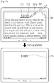
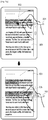
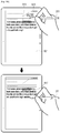
- FIGS. 7A to 7C are views provided to describe an example of an interaction of the touch pen 201 while a document image is displayed in the display 101 according to an embodiment of the present disclosure.
- FIG. 7A illustrates a document image 701, a textualized document 703, a part of document 705, and a partial document image 707.
- the controller 103 may convert the document image 701 into the textualized document 703.
- the controller 103 may control the display 101 to display the partial document image 707 corresponding to the part of document 705.
- the partial document image 707 may be displayed around the position from which the touch was sensed.
- FIG. 7B illustrates the document image 701, a textualized document 715, a part of document image 711, an underline 713, and the touch pen 201.
- the controller 103 may control the display 101 to display the underline 713 on the part of the document image 701 in an area from which the drag operation was sensed and may convert the part of the document image 701 into text.
- the controller 103 may determine the position from the contact or hovering was sensed.
- the controller 103 may control the display 101 to display the underline 713 on a moving trajectory and may convert the document image around the underline 713 into text.
- the controller 103 may display the converted text document 715 in the display 101. In this case, only the part of document image 711 included in the document image 701 may be converted into text.
- FIG. 7C illustrates the document image 701, a textualized document 721, an underline 723, and a partial document image 725.
- the controller 103 may convert the document image 701 into the textualized document 721.
- the controller 103 may control the display 101 to display the partial document image 725 corresponding to the part of text.
- the partial document image 725 may be displayed around the position from which the hovering of the touch pen 201 was sensed.
- the controller 103 may control the display 101 to display the partial document image 725 corresponding to the part of text.
- the partial document image 725 may be displayed around the position from which the contact of the touch pen 201 was sensed.
- FIG. 8 is a view provided to describe an example of a hovering interaction of the touch pen 201 according to an embodiment of the present disclosure.
- the display 101 displays a document 801, an application 803, and the touch pen 201.
- the controller 103 may sense the hovering from the arbitrary position of the document.
- the controller 103 may extract a character and number displayed at the position from which the hovering was sensed and call an application corresponding to the extracted character and number.
- the controller 103 may connect the extracted character and number to the application 803. That is, the controller 103 may use the extracted character and number as an input of the application.
- controller 103 may control the display 101 to display an execution result of the application obtained by inputting the extracted character and number into the application.
- the application 803 may be a widget.
- the widget refers to a mini application which is one of the GUIs for facilitating an interaction between a user and an application or between the user and an operating system (OS).
- OS operating system
- the widget may include a dictionary widget, a weather widget, a calculator widget, a clock widget, a phone widget, etc.
- the controller 103 may control the display 101 to display a dictionary widget of the application 803.
- the controller 103 may input the selected word 801a into a search box of the dictionary widget of the application 803 and may control the display 101 to display the search result in the dictionary widget of the application 803.
- the controller 103 may input the word 'round' into the dictionary widget of the application 803 and may control the display 101 to search a meaning of the word 'round' and display the search result in the dictionary widget of the application 803.
- the controller 103 may execute an application or widget where the number may be used as an input.
- the controller 103 may control the display 101 to display a phone widget and may make a phone call.
- the controller 103 may control the display 101 to display a calculator widget in the display 101.
- FIGS. 9A and 9B are views provided to describe a method for applying a format by using the touch pen 201 according to an embodiment of the present disclosure.
- the display 101 displays a document 901, a first area 903, a second area 905, and the touch pen 201.
- a format may be applied to the document 901 displayed in the display 101.
- the first area 903 and the second area 905 may be a part of areas selected from the document.
- the touch pen 201 may operate in a first mode or in a second mode.
- the touch pen 201 includes a button.
- the touch pen 201 may operate in the first mode.
- the touch pen 201 may operate in the second mode.
- the controller 103 may receive a first signal from the touch pen 201.
- the controller 103 may receive the first signal from the sensor 105.
- the controller 103 may receive a second signal from the touch pen 201.
- the controller 103 may receive the second signal from the sensor 105.
- the controller 103 may select the first area 903 and copy a format applied to the first area 903. In this case, in response to the user brining the touch pen 201 into contact with the second area 905, the controller 103 may apply the format of the first area 903 to the second area 905.
- the controller 103 may acquire the format of the first area 903. In response to the user input being received from the second area 905 of the display 101 after the format of the first area 903 is acquired, the controller 103 may apply the format of the first area 903 to the second area 905.
- the controller 103 may select the first area 903.
- the selected first area 903 may be reversed or highlighted.
- the format of the selected first area 903 may be extracted.
- the controller 103 may apply the format of the first area 903 to the second format 905. That is, in response to a base color of the first area 903 being yellow, the controller 103 may control the display 101 to display a base color of the second area 905 in yellow.
- the controller 103 may control the display 101 to display a font of the second area 905 in the Gothic font. In response to the font of the first area 903 being an Italic font, the controller 103 may control the display 101 to display the font of the second area 905 in the Italic font.
- FIG. 9B illustrates the document 901, a first area 913, a second area 917, a format list 915, and the touch pen 201.
- the controller 103 may select the first area 913 and control the display 101 to highlight the selected area.
- the format list 915 applied to the first area 913 may be displayed around the first area 913 which come into contact with the touch pen 201.
- the controller 103 may control the display 101 to display the format list 915 applied to the first area 913 around the first area 913 which come into contact with the touch pen 201.
- the controller 103 may apply the format applied to the second area 917. That is, the format of the first area 913 may be applied to the second area 917.
- the controller 103 may determine the first area 913 based on a moving distance of the touch pen 201. That is, in response to the drag operation by the touch pen 201 being received in the first area 913 of the document, the controller 103 may acquire the format applied to the first area 913 and control the display 101 to display the format list 915 applied to the first area 913 around the first area 913.
- the controller 103 may control the display 101 to apply the selected format to the second area 917 and display the second area 917.
- the format list 915 applied to the first area 913 may be displayed around the first area 913.
- the controller 103 may select the touched format.
- the controller 103 may apply the selected format to the second area 917.
- the second area 917 may be displayed in bold.
- FIGS. 10A and 10B are views provided to describe a method for applying a format according to an embodiment of the present disclosure.
- FIG. 10A illustrates a document 1001, a format list 1003, a format 1003a, a selection area 1005, a format application area 1007, the touch pen 201, and the button 201a.
- the controller 103 may apply the selected format 1003a.
- the display 101 may display the format application area 1007 to which the format was applied.
- the controller 103 may remove the applied format 1003a. That is, the selected format 1003a may be applied only when the button 201a of the touch pen 201 is pressed.
- the controller 103 may apply the selected format 1003a.
- the display 101 may display the format application area 1007 to which the format was applied.
- the applied format 1003a may be applied continuously unless any release command is received.
- the selected format 1003a may be also applied when the user inputs the handwriting by using the touch pen 201.
- FIG. 10B illustrates a document 1011, a format list 1013, a format 1013a, the selection area 1005, the format application area 1007, the touch pen 201, and the button 201a.
- the controller 103 may apply the selected format 1013a.
- the display 101 may display the format application area 1007 to which the format was applied.
- the controller 103 may remove the selected format 1003a. That is, the selected format may be applied in response to the user touching the format list 1013 by using the finger and maintaining the touch.
- the controller 103 may apply the format selected in the first area 1013 to the second area 1005.
- the first area 1013 may be a format list, and the second area 1005 may be a part of the document.
- FIG. 11 is a view provided to describe a method of setting a user format according to an embodiment of the present disclosure.
- FIG. 11 illustrates a document 1101, a user-designated format list 1103, a user-selected format 1103a, the touch pen 201, and a button 102a.
- the user may store and manage a certain format of the touch pen 201 to be used for a particular purpose. That is, the user may store a user-designated format in the user-designated format list 1103 and call the format according to the need.
- the controller 103 may control the display 101 to display the user-designated format list 1103 in the upper part of the screen.
- the user-designated format list 1103 may include a format that the user uses frequently.
- the controller 103 may apply the user-selected format 1103a.
- the controller may apply the user-selected format 1103a.
- FIGS. 12A to 12C are views provided to describe an embodiment of magnifying a format menu of the touch pen 201 according to a magnification of a screen according to an embodiment of the present disclosure.
- FIG. 12A illustrates a document 1201, a handwriting image 1203, a format list 1205, and the touch pen 201.
- the display 101 displays the document 1201 in an original magnification.
- the controller 103 may determine a display magnification of the format list 1205 based on the magnification of the document 1201 displayed in the display 101.
- the controller 103 may control the display 101 to display the format list 1205 in an original size.
- the handwriting image 1203 may be also displayed in an original size.
- FIG. 12B illustrates a document 1211, a handwriting image 1213, a format list 1215, and the touch pen 201.
- the display 101 may magnify and display the document 1211 by 200% of the original magnification.
- the controller 103 may determine the display magnification of the format list 1215 based on the magnification of the document 1211 displayed in the display 101.
- the controller 103 may control the display 101 to magnify and display the format list 1215 by 200% of the original magnification.
- the handwriting image 1203 may be also magnified and displayed by 200% of the original magnification.
- FIG. 12C illustrates a document 1221, a handwriting image 1223, a format list 1225, and the touch pen 201.
- the display 101 may reduce and display the document 1221 by 50% of the original magnification.
- the controller 103 may determine the display magnification of the format list 1225 based on the magnification of the document 1221 displayed in the display 101.
- the controller 103 may control the display 101 to reduce and display the format list 1225 by 50% of the original magnification.
- the handwriting image 1223 may be also reduced and displayed by 50% of the original magnification.
- the controller 103 may determine the magnification of the content displayed in the display 101 and control the display 101 to display the format of the touch pen 201 based on the determined magnification.
- FIGS. 13A to 13C are views provided to describe a method for converting a handwriting input mode and a gesture input mode by using the touch pen 201 according to an embodiment of the present disclosure.
- the input of the touch pen 201 may be recognized as the handwriting image.
- the input of the touch pen 201 may be recognized as a command to execute a particular function.
- the controller 103 may recognize the input handwriting as the handwriting image and convert the input handwriting into corresponding text.
- the controller 103 may play back music.
- the controller 103 may stop the playback.
- FIG. 13A illustrates a first area 1301 and a second area 1303 of the display 101.
- the controller 103 may divide the display 101 into the first area 1301 and the second area 1303 based on a direction of the electronic apparatus 100. That is, in response to touch information by the touch pen 201 being received in the display 101, the controller 103 may divide the display 101 into the first area 1301 and the second area 1303 based on the direction of the electronic apparatus 100.
- the controller 103 may determine the first area 1301 and the second area 1303 based on the direction of the electronic apparatus 100.
- the controller 103 may determine an upper area of the display 101 as the second area 1303.
- the controller 103 may receive the signal based on the contact of the touch pen 201 and may do not receive or may ignore a signal based on a touch of a finger.
- the controller 103 may receive the signal based on the touch of the finger.
- FIG. 13B illustrates the first area 1301, the second area 1303, and the touch pen 201.
- the controller 103 may set the first area 1301 as a first mode.
- the first mode may be the handwriting input mode.
- the controller 103 may control the display 101 to display the handwriting image based on the received signal.
- the controller 103 may set the first area 1301 as a second mode.
- the second mode may be the gesture input mode.
- the controller 103 may determine a gesture based on the received signal and control to execute a command or function corresponding to the determined gesture.
- FIG. 13C illustrates the first area 1301, a second area 1305, and the touch pen 201.
- the controller 103 may determine the first area 1301 and the second area 1305 by considering the direction of the electronic apparatus 100. A position of the second area 1305 may vary according to whether the direction of the electronic apparatus 100 is a horizontal direction or a vertical direction.
- the controller 103 may determine the first area 1301 and the second area 1305 based on the direction of the electronic apparatus 100.
- the controller 103 may inactivate a touch input of a finger in the first area 1301 and activate the touch input of the finger in the second area 1305.
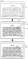
- FIG. 14 is a flowchart provided to describe a method for changing a display direction of a graphical object displayed in the display 101 based on an input of the touch pen 201 according to an embodiment of the present disclosure.
- the electronic apparatus 100 displays a graphical object in the display 101 at operation S1401.
- the graphical object may be displayed in a graphical object display layer.
- the graphical object display layer may display a character, an icon and button for executing a content application, etc.
- the electronic apparatus 100 may sense an input of the touch pen 201 in the display 101 at operation S1403.
- the display 101 may display the graphical object display layer and a handwriting input layer.
- the electronic apparatus 100 may display a handwriting image in the handwriting input layer based on the input of the touch pen 201.
- the electronic apparatus 100 may display the handwriting image in the handwriting input layer.
- the electronic apparatus 100 may change the display direction of the graphical object displayed in the display 101 based on the input of the touch pen 201 at operation S 1405.
- the electronic apparatus 100 may receive a signal based on the contact of the touch pen 201 from the sensor 105.
- the electronic apparatus 100 may determine an angle between the touch pen 201 and the display 101 and a direction by processing the received signal. That is, the electronic apparatus 100 may determine a tilt angle and direction of the touch pen 201.
- the tilt angle and direction of the touch pen 201 may be tilt information of the touch pen 201.
- the electronic apparatus 100 may determine a direction of a handwriting input of the touch pen 201 by using the tilt information of the touch pen 201 and determine the display direction of the graphical object based on the direction of the handwriting input.
- the touch pen 201 may output status information, such as, the tilt information of the touch pen 201, autonomously.
- the electronic apparatus 100 may receive a signal output from the touch pen 201 and determine the tilt information of the touch pen 201 based on the received signal.
- the electronic apparatus 100 may determine a tilt direction of the touch pen 201 based on the tilt information of the touch pen 201 and determine the display direction of the graphical object based on the tilt direction of the touch pen 201.
- the electronic apparatus 100 may rotate the display direction of the graphical object so that the tilt direction of the touch pen 201 and the display direction of the graphical object become opposite to each other.
- the electronic apparatus 100 may display the handwriting image in the second layer based on the input of the touch pen 201. In addition, the electronic apparatus 100 may display the graphical object in the first layer and display the handwriting image displayed based on the input of the touch pen 201 in the second layer.
- the electronic apparatus 100 may fix the second layer and rotate or fix a display direction of the first layer based on the tilt direction of the touch pen 201.
- the screen displayed in the display 101 may include the first layer and the second layer.
- the first layer may be the graphical object display layer
- the second layer may be a touch pen input layer.
- the electronic apparatus 100 may display the graphical object in the first layer and receive a signal based on the input of the touch pen 201 through the second layer.
- the electronic apparatus 100 may display the handwriting image in the second layer based on the input of the touch pen 201.
- the electronic apparatus 100 may change the display direction of the graphical object displayed in the first layer based on the input of the touch pen 201.
- the electronic apparatus 100 may determine the tilt direction of the touch pen 201 based on the input of the touch pen 201 and may change the display direction of the graphical object displayed in the first layer based on the tilt direction of the touch pen 201.
- the electronic apparatus 100 may fix a direction of the second layer although the display direction of the graphical object is changed.
- an apparatus may include a processor, a memory for storing and executing program data, a permanent storage, for example, a disk drive, a communication port for communicating with an external apparatus, and a user interface apparatus, for example, a touch panel, a key, a button, etc.
- the methods realized as a software module or an algorithm may be stored in a computer readable recording medium in a form of computer readable codes or program commands which are executable in the processor.
- the computer readable recording medium may include a magnetic storage medium (for example, read only memory (ROM), random access memory (RAM), floppy disk, hard disk, etc.) and an optical reader (for example, compact disc ROM (CD-ROM), digital versatile disc (DVD), etc.)
- the computer readable recording medium may store and execute a code which is distributed to computer systems interconnected through a network and is readable by a computer in a distribution method.
- the medium may be read by the computer, stored in a memory, and executed in the processor.
- the present embodiments may be expressed by functional blocks and various processing operations.
- the functional blocks may be realized as various numbers of hardware and/or software elements for performing particular functions.
- the various embodiments may employ integrated circuits, such as, memory, processing, logic, look-up table, etc.
- the integrated circuits may perform diverse functions according to control of one or more microprocessors or other control devices.
- the elements may be executed as software programming or software elements
- the present embodiments may include diverse algorithms realized through a combination of a data structure, processes, routines, or other programming elements and may be realized as a programming language or scripting language, such as, C, C++, Java, assembler, etc.
- the functional aspects may be realized as an algorithm executed in one or more processors.
- the present embodiments may employ the related art for electronic configuration, signal processing, and/or data processing.
- the terms 'mechanism,' 'element,' 'means,' and 'component' may be interpreted broadly and are not limited to a mechanical and physical component. The terms may include the meaning of a series of processing operations of software (routines) in connection with a processor and the like.
Landscapes
- Engineering & Computer Science (AREA)
- Theoretical Computer Science (AREA)
- General Engineering & Computer Science (AREA)
- Human Computer Interaction (AREA)
- Physics & Mathematics (AREA)
- General Physics & Mathematics (AREA)
- Computer Hardware Design (AREA)
- User Interface Of Digital Computer (AREA)
Claims (7)
- Elektronische Vorrichtung (100), umfassend:einen Kommunikator (107), dazu konfiguriert, eine Signalausgabe aus einem Touchscreen-Stift (201) zu empfangen;einen Sensor (105), dazu konfiguriert, eine Eingabe des Touchscreen-Stiftes (201) abzufühlen und ein Signal, das der Eingabe des Touchscreen-Stiftes (201) entspricht, auszugeben, wobei das Signal Neigungsinformationen des Touchscreen-Stiftes (201) umfasst; undein Display (101), dazu konfiguriert, mindestens ein Grafikobjekt (101a, 101b) anzuzeigen;eine Steuereinrichtung (103), für Folgendes konfiguriert:als Antwort auf die empfangene Signalausgabe aus dem Sensor (105), Steuern des Displays (101), ein Handschriftbild (305, 403b, 603, 603a, 605, 605a, 607, 607a, 609, 609a, 1203, 1213, 1223) anzuzeigen, das der Eingabe des Touchscreen-Stiftes (201) entspricht, während das mindestens eine Grafikobjekt (101a, 101b) angezeigt wird,Bestimmen, ob ein Rechtshändermodus zu verwenden ist oder ein Linkshändermodus zu verwenden ist, auf der Grundlage eines Winkels zwischen dem Touchscreen-Stift (201) und dem Display (101), enthalten in den Neigungsinformationen, und einer Bewegungsrichtung der Handschrift,Bestimmen einer Anzeigerichtung des mindestens einen Grafikobjektes (101a, 101b), angezeigt auf dem Display (101),Erkennen einer Anzeigerichtung des Handschriftbildes (305, 403b, 603, 603a, 605, 605a, 607, 607a, 609, 609a, 1203, 1213, 1223) auf der Grundlage der Neigungsinformationen des Touchscreen-Stiftes (201) und der Bewegungsrichtung der Handschrift,auf der Grundlage einer Nichtübereinstimmung der bestimmten Anzeigerichtung des mindestens einen Grafikobjektes (101a, 101b) mit der erkannten Anzeigerichtung des Handschriftbildes (305, 403b, 603, 603a, 605, 605a, 607, 607a, 609, 609a, 1203, 1213, 1223), Ändern der Anzeigerichtung des mindestens einen Grafikobjektes (101a, 101b), so dass die Anzeigerichtung des Grafikobjektes (101a, 101b) der Anzeigerichtung des Handschriftbildes (305, 403b, 603, 603a, 605, 605a, 607, 607a, 609, 609a, 1203, 1213, 1223) entspricht, undSteuern des Displays (101), das mindestens eine Grafikobjekt (101a, 101b), zu drehen auf der Grundlage der geänderten Anzeigerichtung des mindestens einen Grafikobjektes (101a, 101b), anzuzeigen, während die erkannte Anzeigerichtung des Handschriftbildes (305, 403b, 603, 603a, 605, 605a, 607, 607a, 609, 609a, 1203, 1213, 1223) beibehalten wird.
- Elektronische Vorrichtung (100) nach Anspruch 1, wobei die Steuereinrichtung (103) das Display (101) steuert, das mindestens eine Grafikobjekt (101a, 101b) in einer ersten Schicht (301) anzuzeigen und das Handschriftbild (305, 403b, 603, 603a, 605, 605a, 607, 607a, 609, 609a, 1203, 1213, 1223), angezeigt auf der Grundlage der Eingabe des Touchscreen-Stiftes (201), in einer zweiten Schicht (303) anzuzeigen.
- Elektronische Vorrichtung (100) nach Anspruch 2, wobei die Steuereinrichtung (103) das Display (101) steuert, die zweite Schicht (303) zu fixieren und die Anzeigerichtung des mindestens einen Grafikobjektes (101a, 101b) in der ersten Schicht (301) auf der Grundlage der Neigungsrichtung des Touchscreen-Stiftes (201) zu ändern.
- Elektronische Vorrichtung (100) nach Anspruch 1, wobei das Display (101) dazu konfiguriert ist, eine erste Schicht (301) und eine zweite Schicht (303) aufzuweisen, das mindestens eine Grafikobjekt (101a, 101b) in der ersten Schicht (301) anzuzeigen und das Handschriftbild (305, 403b, 603, 603a, 605, 605a, 607, 607a, 609, 609a, 1203, 1213, 1223) auf der Grundlage der Eingabe des Touchscreen-Stiftes (201) in der zweiten Schicht (303) anzuzeigen; und
die Steuereinrichtung (103) dazu konfiguriert ist, das Display (101) zu steuern, eine Anzeigerichtung des mindestens einen Grafikobjektes (101a, 101b), angezeigt in der ersten Schicht (301), zu ändern. - Elektronische Vorrichtung (100) nach Anspruch 4, wobei die Steuereinrichtung (103) eine Neigungsrichtung des Touchscreen-Stiftes (201) auf der Grundlage der Signalausgabe aus dem Sensor (105) bestimmt und das Display (101) steuert, die Anzeigerichtung des mindestens einen Grafikobjektes (101a, 101b), angezeigt in der ersten Schicht (301), gemäß der Neigungsrichtung des Touchscreen-Stiftes (201) zu ändern.
- Elektronische Vorrichtung (100) nach Anspruch 5, wobei die Steuereinrichtung (103) das Display (101) steuert, trotz einer Änderung einer Richtung der ersten Schicht (301) eine Richtung der zweiten Schicht (303) unverändert beizubehalten.
- Verfahren zur Anzeige eines Grafikobjektes (101a, 101b) einer elektronischen Vorrichtung (100), wobei das Verfahren umfasst:Abfühlen einer Eingabe eines Touchscreen-Stiftes (201) und Ausgeben eines Signals, das der Eingabe des Touchscreen-Stiftes (201) entspricht, wobei das Signal Neigungsinformationen des Touchscreen-Stiftes (201) umfasst;als Antwort auf den Empfang der Eingabe des Touchscreen-Stiftes (201), Anzeigen, auf einem Display (101), eines Handschriftbildes (305, 403b, 603, 603a, 605, 605a, 607, 607a, 609, 609a, 1203, 1213, 1223), das der Eingabe des Touchscreen-Stiftes (201) entspricht, während mindestens ein Grafikobjekt (101a, 101b) angezeigt wird;Bestimmen, ob ein Rechtshändermodus zu verwenden ist oder ein Linkshändermodus zu verwenden ist, auf der Grundlage eines Winkels zwischen dem Touchscreen-Stift (201) und dem Display (101), enthalten in den Neigungsinformationen, und einer Bewegungsrichtung der Handschrift;Bestimmen einer Anzeigerichtung des mindestens einen Grafikobjektes (101a, 101b), angezeigt auf dem Display (101);Erkennen einer Anzeigerichtung des Handschriftbildes (305, 403b, 603, 603a, 605, 605a, 607, 607a, 609, 609a, 1203, 1213, 1223) auf der Grundlage der Neigungsinformationen des Touchscreen-Stiftes (201) und einer Bewegungsrichtung der Handschrift,auf der Grundlage einer Nichtübereinstimmung der bestimmten Anzeigerichtung des mindestens einen Grafikobjektes (101a, 101b) mit der erkannten Anzeigerichtung des Handschriftbildes (305, 403b, 603, 603a, 605, 605a, 607, 607a, 609, 609a, 1203, 1213, 1223), Ändern der Anzeigerichtung des mindestens einen Grafikobjektes (101a, 101b), so dass die Anzeigerichtung des Grafikobjektes (101a, 101b) der Anzeigerichtung des Handschriftbildes (305, 403b, 603, 603a, 605, 605a, 607, 607a, 609, 609a, 1203, 1213, 1223) entspricht, undAnzeigen des mindestens einen Grafikobjektes (101a, 101b), zu drehen auf der Grundlage der geänderten Anzeigerichtung des mindestens einen Grafikobjektes (101a, 101b), während die erkannte Anzeigerichtung des Handschriftbildes (305, 403b, 603, 603a, 605, 605a, 607, 607a, 609, 609a, 1203, 1213, 1223) beibehalten wird.
Applications Claiming Priority (2)
| Application Number | Priority Date | Filing Date | Title |
|---|---|---|---|
| KR1020140168323A KR102411868B1 (ko) | 2014-11-28 | 2014-11-28 | 전자장치 및 그래픽 오브젝트 표시 방법 |
| PCT/KR2015/012374 WO2016085186A1 (en) | 2014-11-28 | 2015-11-18 | Electronic apparatus and method for displaying graphical object thereof |
Publications (3)
| Publication Number | Publication Date |
|---|---|
| EP3224703A1 EP3224703A1 (de) | 2017-10-04 |
| EP3224703A4 EP3224703A4 (de) | 2017-10-04 |
| EP3224703B1 true EP3224703B1 (de) | 2022-01-05 |
Family
ID=56074658
Family Applications (1)
| Application Number | Title | Priority Date | Filing Date |
|---|---|---|---|
| EP15863317.2A Not-in-force EP3224703B1 (de) | 2014-11-28 | 2015-11-18 | Elektronische vorrichtung und verfahren zur anzeige von grafikobjekten davon |
Country Status (5)
| Country | Link |
|---|---|
| US (1) | US10146341B2 (de) |
| EP (1) | EP3224703B1 (de) |
| KR (1) | KR102411868B1 (de) |
| CN (1) | CN107003807B (de) |
| WO (1) | WO2016085186A1 (de) |
Families Citing this family (10)
| Publication number | Priority date | Publication date | Assignee | Title |
|---|---|---|---|---|
| CN106462142B (zh) * | 2014-06-19 | 2019-03-29 | 株式会社牧野铣床制作所 | 机床的控制装置 |
| JP6557300B2 (ja) * | 2017-08-15 | 2019-08-07 | ファナック株式会社 | タッチパネルの検査装置、及びタッチパネルの検査方法 |
| KR102656447B1 (ko) * | 2018-02-27 | 2024-04-12 | 삼성전자주식회사 | 컨트롤러와 접촉된 신체 부위에 따라 그래픽 객체를 다르게 표시하는 방법 및 전자 장치 |
| CN109614178A (zh) * | 2018-09-04 | 2019-04-12 | 广州视源电子科技股份有限公司 | 批注显示方法、装置、设备和存储介质 |
| KR20220086896A (ko) | 2020-12-17 | 2022-06-24 | 삼성전자주식회사 | 필기 입력을 처리하는 전자 장치 및 그 작동 방법 |
| US11797173B2 (en) * | 2020-12-28 | 2023-10-24 | Microsoft Technology Licensing, Llc | System and method of providing digital ink optimized user interface elements |
| JP2023044182A (ja) * | 2021-09-17 | 2023-03-30 | レノボ・シンガポール・プライベート・リミテッド | 情報処理装置、及び制御方法 |
| US11537239B1 (en) * | 2022-01-14 | 2022-12-27 | Microsoft Technology Licensing, Llc | Diffusion-based handedness classification for touch-based input |
| JP2023180655A (ja) * | 2022-06-10 | 2023-12-21 | セイコーエプソン株式会社 | 印刷装置 |
| EP4653989A4 (de) * | 2023-03-20 | 2026-04-29 | Samsung Electronics Co Ltd | Elektronische vorrichtung zur verarbeitung der eingabe eines eingabestifts und betriebsverfahren dafür |
Family Cites Families (15)
| Publication number | Priority date | Publication date | Assignee | Title |
|---|---|---|---|---|
| JP3161794B2 (ja) | 1992-03-05 | 2001-04-25 | 松下電器産業株式会社 | ペン入力装置及びペン入力方法 |
| JP2009237836A (ja) | 2008-03-27 | 2009-10-15 | Sanyo Electric Co Ltd | 手書き入力パネルを備えた車載用電子装置 |
| KR20100012701A (ko) * | 2008-07-29 | 2010-02-08 | 엘지전자 주식회사 | 펜 타입 휴대용 입력 장치 및 그 궤적 보정 방법 |
| US9864440B2 (en) | 2010-06-11 | 2018-01-09 | Microsoft Technology Licensing, Llc | Object orientation detection with a digitizer |
| KR101155349B1 (ko) | 2011-02-11 | 2012-06-15 | 주식회사바이제로 | 필기이미지입력장치 |
| US8638320B2 (en) | 2011-06-22 | 2014-01-28 | Apple Inc. | Stylus orientation detection |
| CN102402360A (zh) * | 2011-11-23 | 2012-04-04 | 段西京 | 手写显示屏、手写输入笔及手写输入方法 |
| US20140022218A1 (en) | 2012-07-20 | 2014-01-23 | Research In Motion Limited | Orientation sensing stylus |
| KR20140014551A (ko) * | 2012-07-24 | 2014-02-06 | 삼성전자주식회사 | 클라우드 서비스 기반의 메모 기능 제공 방법 및 시스템과 이를 지원하는 단말기 |
| KR101997450B1 (ko) * | 2013-02-04 | 2019-07-08 | 엘지전자 주식회사 | 이동 단말기 및 이동 단말기 제어방법 |
| US9075464B2 (en) * | 2013-01-30 | 2015-07-07 | Blackberry Limited | Stylus based object modification on a touch-sensitive display |
| JP2014241005A (ja) * | 2013-06-11 | 2014-12-25 | 株式会社東芝 | 表示制御装置、表示制御方法、及び表示制御プログラム |
| JP2015043159A (ja) * | 2013-08-26 | 2015-03-05 | シャープ株式会社 | タッチパネル装置及び表示装置 |
| US9400570B2 (en) * | 2014-11-14 | 2016-07-26 | Apple Inc. | Stylus with inertial sensor |
| JP5939594B2 (ja) * | 2014-11-25 | 2016-06-22 | インターナショナル・ビジネス・マシーンズ・コーポレーションInternational Business Machines Corporation | 画像の拡大又は縮小を行う装置並びに方法 |
-
2014
- 2014-11-28 KR KR1020140168323A patent/KR102411868B1/ko not_active Expired - Fee Related
-
2015
- 2015-11-16 US US14/942,371 patent/US10146341B2/en active Active
- 2015-11-18 EP EP15863317.2A patent/EP3224703B1/de not_active Not-in-force
- 2015-11-18 CN CN201580065515.2A patent/CN107003807B/zh not_active Expired - Fee Related
- 2015-11-18 WO PCT/KR2015/012374 patent/WO2016085186A1/en not_active Ceased
Also Published As
| Publication number | Publication date |
|---|---|
| CN107003807B (zh) | 2021-06-04 |
| KR20160064560A (ko) | 2016-06-08 |
| EP3224703A1 (de) | 2017-10-04 |
| EP3224703A4 (de) | 2017-10-04 |
| US20160154474A1 (en) | 2016-06-02 |
| CN107003807A (zh) | 2017-08-01 |
| WO2016085186A1 (en) | 2016-06-02 |
| KR102411868B1 (ko) | 2022-06-23 |
| US10146341B2 (en) | 2018-12-04 |
Similar Documents
| Publication | Publication Date | Title |
|---|---|---|
| EP3224703B1 (de) | Elektronische vorrichtung und verfahren zur anzeige von grafikobjekten davon | |
| US10698564B2 (en) | User terminal device and displaying method thereof | |
| US9411484B2 (en) | Mobile device with memo function and method for controlling the device | |
| JP6054892B2 (ja) | 複数のディスプレイに対するアプリケーション画像の表示方法、電子機器およびコンピュータ・プログラム | |
| JP6038927B2 (ja) | 指向的ユーザジェスチャに基づくコンテンツナビゲーション方向の確立 | |
| US10747391B2 (en) | Method and device for executing applications through application selection screen | |
| KR102009054B1 (ko) | 제한된 디스플레이 장치에서의 수식 입력 기법 | |
| EP2801899A1 (de) | Verfahren, Vorrichtung und System zur Bereitstellung einer privaten Seite | |
| KR102205283B1 (ko) | 적어도 하나의 어플리케이션을 실행하는 전자 장치 및 그 제어 방법 | |
| KR20160033547A (ko) | 컨텐트를 스타일링하는 장치 및 방법 | |
| KR102381051B1 (ko) | 키패드를 표시하는 전자장치 및 그의 키패드 표시 방법 | |
| EP2965181B1 (de) | Verbesserte leinwandumgebungen | |
| CN104704454B (zh) | 用于处理多点输入的终端和方法 | |
| US20140123036A1 (en) | Touch screen display process | |
| KR20120040970A (ko) | 디스플레이에서 제스쳐를 인식하는 방법 및 그 장치 | |
| CN108803997A (zh) | 智能交互平板的操作方法、装置以及智能交互平板 | |
| US11693556B2 (en) | Creating tables using gestures | |
| CN103809903A (zh) | 用于控制虚拟屏幕的方法和装置 | |
| EP2818998A1 (de) | Verfahren und Vorrichtung zur Erzeugung eines elektronischen Dokuments in einem mobilen Endgerät | |
| KR101529886B1 (ko) | 제스처 기반 3d 그래픽 사용자 인터페이스 제공방법 | |
| KR102205235B1 (ko) | 즐겨찾기모드 조작방법 및 이를 수행하는 터치 스크린을 포함하는 장치 | |
| TW201502959A (zh) | 強化的畫布環境 |
Legal Events
| Date | Code | Title | Description |
|---|---|---|---|
| STAA | Information on the status of an ep patent application or granted ep patent |
Free format text: STATUS: THE INTERNATIONAL PUBLICATION HAS BEEN MADE |
|
| PUAI | Public reference made under article 153(3) epc to a published international application that has entered the european phase |
Free format text: ORIGINAL CODE: 0009012 |
|
| STAA | Information on the status of an ep patent application or granted ep patent |
Free format text: STATUS: REQUEST FOR EXAMINATION WAS MADE |
|
| 17P | Request for examination filed |
Effective date: 20170427 |
|
| A4 | Supplementary search report drawn up and despatched |
Effective date: 20170817 |
|
| AK | Designated contracting states |
Kind code of ref document: A1 Designated state(s): AL AT BE BG CH CY CZ DE DK EE ES FI FR GB GR HR HU IE IS IT LI LT LU LV MC MK MT NL NO PL PT RO RS SE SI SK SM TR |
|
| AX | Request for extension of the european patent |
Extension state: BA ME |
|
| DAV | Request for validation of the european patent (deleted) | ||
| DAX | Request for extension of the european patent (deleted) | ||
| STAA | Information on the status of an ep patent application or granted ep patent |
Free format text: STATUS: EXAMINATION IS IN PROGRESS |
|
| 17Q | First examination report despatched |
Effective date: 20190730 |
|
| REG | Reference to a national code |
Ref country code: DE Ref legal event code: R079 Ref document number: 602015076331 Country of ref document: DE Free format text: PREVIOUS MAIN CLASS: G06F0003048000 Ipc: G06F0003048800 |
|
| GRAP | Despatch of communication of intention to grant a patent |
Free format text: ORIGINAL CODE: EPIDOSNIGR1 |
|
| STAA | Information on the status of an ep patent application or granted ep patent |
Free format text: STATUS: GRANT OF PATENT IS INTENDED |
|
| RIC1 | Information provided on ipc code assigned before grant |
Ipc: G06F 3/0488 20130101AFI20210609BHEP Ipc: G06F 1/16 20060101ALI20210609BHEP Ipc: G06F 3/0354 20130101ALI20210609BHEP |
|
| INTG | Intention to grant announced |
Effective date: 20210628 |
|
| GRAS | Grant fee paid |
Free format text: ORIGINAL CODE: EPIDOSNIGR3 |
|
| GRAA | (expected) grant |
Free format text: ORIGINAL CODE: 0009210 |
|
| STAA | Information on the status of an ep patent application or granted ep patent |
Free format text: STATUS: THE PATENT HAS BEEN GRANTED |
|
| AK | Designated contracting states |
Kind code of ref document: B1 Designated state(s): AL AT BE BG CH CY CZ DE DK EE ES FI FR GB GR HR HU IE IS IT LI LT LU LV MC MK MT NL NO PL PT RO RS SE SI SK SM TR |
|
| REG | Reference to a national code |
Ref country code: GB Ref legal event code: FG4D |
|
| REG | Reference to a national code |
Ref country code: CH Ref legal event code: EP |
|
| REG | Reference to a national code |
Ref country code: AT Ref legal event code: REF Ref document number: 1461169 Country of ref document: AT Kind code of ref document: T Effective date: 20220115 |
|
| REG | Reference to a national code |
Ref country code: DE Ref legal event code: R096 Ref document number: 602015076331 Country of ref document: DE |
|
| REG | Reference to a national code |
Ref country code: IE Ref legal event code: FG4D |
|
| REG | Reference to a national code |
Ref country code: LT Ref legal event code: MG9D |
|
| REG | Reference to a national code |
Ref country code: NL Ref legal event code: MP Effective date: 20220105 |
|
| REG | Reference to a national code |
Ref country code: AT Ref legal event code: MK05 Ref document number: 1461169 Country of ref document: AT Kind code of ref document: T Effective date: 20220105 |
|
| PG25 | Lapsed in a contracting state [announced via postgrant information from national office to epo] |
Ref country code: NL Free format text: LAPSE BECAUSE OF FAILURE TO SUBMIT A TRANSLATION OF THE DESCRIPTION OR TO PAY THE FEE WITHIN THE PRESCRIBED TIME-LIMIT Effective date: 20220105 |
|
| PG25 | Lapsed in a contracting state [announced via postgrant information from national office to epo] |
Ref country code: SE Free format text: LAPSE BECAUSE OF FAILURE TO SUBMIT A TRANSLATION OF THE DESCRIPTION OR TO PAY THE FEE WITHIN THE PRESCRIBED TIME-LIMIT Effective date: 20220105 Ref country code: RS Free format text: LAPSE BECAUSE OF FAILURE TO SUBMIT A TRANSLATION OF THE DESCRIPTION OR TO PAY THE FEE WITHIN THE PRESCRIBED TIME-LIMIT Effective date: 20220105 Ref country code: PT Free format text: LAPSE BECAUSE OF FAILURE TO SUBMIT A TRANSLATION OF THE DESCRIPTION OR TO PAY THE FEE WITHIN THE PRESCRIBED TIME-LIMIT Effective date: 20220505 Ref country code: NO Free format text: LAPSE BECAUSE OF FAILURE TO SUBMIT A TRANSLATION OF THE DESCRIPTION OR TO PAY THE FEE WITHIN THE PRESCRIBED TIME-LIMIT Effective date: 20220405 Ref country code: LT Free format text: LAPSE BECAUSE OF FAILURE TO SUBMIT A TRANSLATION OF THE DESCRIPTION OR TO PAY THE FEE WITHIN THE PRESCRIBED TIME-LIMIT Effective date: 20220105 Ref country code: HR Free format text: LAPSE BECAUSE OF FAILURE TO SUBMIT A TRANSLATION OF THE DESCRIPTION OR TO PAY THE FEE WITHIN THE PRESCRIBED TIME-LIMIT Effective date: 20220105 Ref country code: ES Free format text: LAPSE BECAUSE OF FAILURE TO SUBMIT A TRANSLATION OF THE DESCRIPTION OR TO PAY THE FEE WITHIN THE PRESCRIBED TIME-LIMIT Effective date: 20220105 Ref country code: BG Free format text: LAPSE BECAUSE OF FAILURE TO SUBMIT A TRANSLATION OF THE DESCRIPTION OR TO PAY THE FEE WITHIN THE PRESCRIBED TIME-LIMIT Effective date: 20220405 |
|
| PG25 | Lapsed in a contracting state [announced via postgrant information from national office to epo] |
Ref country code: PL Free format text: LAPSE BECAUSE OF FAILURE TO SUBMIT A TRANSLATION OF THE DESCRIPTION OR TO PAY THE FEE WITHIN THE PRESCRIBED TIME-LIMIT Effective date: 20220105 Ref country code: LV Free format text: LAPSE BECAUSE OF FAILURE TO SUBMIT A TRANSLATION OF THE DESCRIPTION OR TO PAY THE FEE WITHIN THE PRESCRIBED TIME-LIMIT Effective date: 20220105 Ref country code: GR Free format text: LAPSE BECAUSE OF FAILURE TO SUBMIT A TRANSLATION OF THE DESCRIPTION OR TO PAY THE FEE WITHIN THE PRESCRIBED TIME-LIMIT Effective date: 20220406 Ref country code: FI Free format text: LAPSE BECAUSE OF FAILURE TO SUBMIT A TRANSLATION OF THE DESCRIPTION OR TO PAY THE FEE WITHIN THE PRESCRIBED TIME-LIMIT Effective date: 20220105 Ref country code: AT Free format text: LAPSE BECAUSE OF FAILURE TO SUBMIT A TRANSLATION OF THE DESCRIPTION OR TO PAY THE FEE WITHIN THE PRESCRIBED TIME-LIMIT Effective date: 20220105 |
|
| PG25 | Lapsed in a contracting state [announced via postgrant information from national office to epo] |
Ref country code: IS Free format text: LAPSE BECAUSE OF FAILURE TO SUBMIT A TRANSLATION OF THE DESCRIPTION OR TO PAY THE FEE WITHIN THE PRESCRIBED TIME-LIMIT Effective date: 20220505 |
|
| REG | Reference to a national code |
Ref country code: DE Ref legal event code: R097 Ref document number: 602015076331 Country of ref document: DE |
|
| PG25 | Lapsed in a contracting state [announced via postgrant information from national office to epo] |
Ref country code: SM Free format text: LAPSE BECAUSE OF FAILURE TO SUBMIT A TRANSLATION OF THE DESCRIPTION OR TO PAY THE FEE WITHIN THE PRESCRIBED TIME-LIMIT Effective date: 20220105 Ref country code: SK Free format text: LAPSE BECAUSE OF FAILURE TO SUBMIT A TRANSLATION OF THE DESCRIPTION OR TO PAY THE FEE WITHIN THE PRESCRIBED TIME-LIMIT Effective date: 20220105 Ref country code: RO Free format text: LAPSE BECAUSE OF FAILURE TO SUBMIT A TRANSLATION OF THE DESCRIPTION OR TO PAY THE FEE WITHIN THE PRESCRIBED TIME-LIMIT Effective date: 20220105 Ref country code: EE Free format text: LAPSE BECAUSE OF FAILURE TO SUBMIT A TRANSLATION OF THE DESCRIPTION OR TO PAY THE FEE WITHIN THE PRESCRIBED TIME-LIMIT Effective date: 20220105 Ref country code: DK Free format text: LAPSE BECAUSE OF FAILURE TO SUBMIT A TRANSLATION OF THE DESCRIPTION OR TO PAY THE FEE WITHIN THE PRESCRIBED TIME-LIMIT Effective date: 20220105 Ref country code: CZ Free format text: LAPSE BECAUSE OF FAILURE TO SUBMIT A TRANSLATION OF THE DESCRIPTION OR TO PAY THE FEE WITHIN THE PRESCRIBED TIME-LIMIT Effective date: 20220105 |
|
| PLBE | No opposition filed within time limit |
Free format text: ORIGINAL CODE: 0009261 |
|
| STAA | Information on the status of an ep patent application or granted ep patent |
Free format text: STATUS: NO OPPOSITION FILED WITHIN TIME LIMIT |
|
| PG25 | Lapsed in a contracting state [announced via postgrant information from national office to epo] |
Ref country code: AL Free format text: LAPSE BECAUSE OF FAILURE TO SUBMIT A TRANSLATION OF THE DESCRIPTION OR TO PAY THE FEE WITHIN THE PRESCRIBED TIME-LIMIT Effective date: 20220105 |
|
| 26N | No opposition filed |
Effective date: 20221006 |
|
| PGFP | Annual fee paid to national office [announced via postgrant information from national office to epo] |
Ref country code: GB Payment date: 20221020 Year of fee payment: 8 Ref country code: DE Payment date: 20220621 Year of fee payment: 8 |
|
| PG25 | Lapsed in a contracting state [announced via postgrant information from national office to epo] |
Ref country code: SI Free format text: LAPSE BECAUSE OF FAILURE TO SUBMIT A TRANSLATION OF THE DESCRIPTION OR TO PAY THE FEE WITHIN THE PRESCRIBED TIME-LIMIT Effective date: 20220105 |
|
| PG25 | Lapsed in a contracting state [announced via postgrant information from national office to epo] |
Ref country code: MC Free format text: LAPSE BECAUSE OF FAILURE TO SUBMIT A TRANSLATION OF THE DESCRIPTION OR TO PAY THE FEE WITHIN THE PRESCRIBED TIME-LIMIT Effective date: 20220105 |
|
| REG | Reference to a national code |
Ref country code: CH Ref legal event code: PL |
|
| REG | Reference to a national code |
Ref country code: BE Ref legal event code: MM Effective date: 20221130 |
|
| PG25 | Lapsed in a contracting state [announced via postgrant information from national office to epo] |
Ref country code: LI Free format text: LAPSE BECAUSE OF NON-PAYMENT OF DUE FEES Effective date: 20221130 Ref country code: IT Free format text: LAPSE BECAUSE OF FAILURE TO SUBMIT A TRANSLATION OF THE DESCRIPTION OR TO PAY THE FEE WITHIN THE PRESCRIBED TIME-LIMIT Effective date: 20220105 Ref country code: CH Free format text: LAPSE BECAUSE OF NON-PAYMENT OF DUE FEES Effective date: 20221130 |
|
| PG25 | Lapsed in a contracting state [announced via postgrant information from national office to epo] |
Ref country code: LU Free format text: LAPSE BECAUSE OF NON-PAYMENT OF DUE FEES Effective date: 20221118 |
|
| PG25 | Lapsed in a contracting state [announced via postgrant information from national office to epo] |
Ref country code: IE Free format text: LAPSE BECAUSE OF NON-PAYMENT OF DUE FEES Effective date: 20221118 |
|
| PG25 | Lapsed in a contracting state [announced via postgrant information from national office to epo] |
Ref country code: FR Free format text: LAPSE BECAUSE OF NON-PAYMENT OF DUE FEES Effective date: 20221130 Ref country code: BE Free format text: LAPSE BECAUSE OF NON-PAYMENT OF DUE FEES Effective date: 20221130 |
|
| PG25 | Lapsed in a contracting state [announced via postgrant information from national office to epo] |
Ref country code: HU Free format text: LAPSE BECAUSE OF FAILURE TO SUBMIT A TRANSLATION OF THE DESCRIPTION OR TO PAY THE FEE WITHIN THE PRESCRIBED TIME-LIMIT; INVALID AB INITIO Effective date: 20151118 |
|
| PG25 | Lapsed in a contracting state [announced via postgrant information from national office to epo] |
Ref country code: CY Free format text: LAPSE BECAUSE OF FAILURE TO SUBMIT A TRANSLATION OF THE DESCRIPTION OR TO PAY THE FEE WITHIN THE PRESCRIBED TIME-LIMIT Effective date: 20220105 |
|
| PG25 | Lapsed in a contracting state [announced via postgrant information from national office to epo] |
Ref country code: MK Free format text: LAPSE BECAUSE OF FAILURE TO SUBMIT A TRANSLATION OF THE DESCRIPTION OR TO PAY THE FEE WITHIN THE PRESCRIBED TIME-LIMIT Effective date: 20220105 |
|
| REG | Reference to a national code |
Ref country code: DE Ref legal event code: R119 Ref document number: 602015076331 Country of ref document: DE |
|
| PG25 | Lapsed in a contracting state [announced via postgrant information from national office to epo] |
Ref country code: TR Free format text: LAPSE BECAUSE OF FAILURE TO SUBMIT A TRANSLATION OF THE DESCRIPTION OR TO PAY THE FEE WITHIN THE PRESCRIBED TIME-LIMIT Effective date: 20220105 |
|
| GBPC | Gb: european patent ceased through non-payment of renewal fee |
Effective date: 20231118 |
|
| PG25 | Lapsed in a contracting state [announced via postgrant information from national office to epo] |
Ref country code: MT Free format text: LAPSE BECAUSE OF FAILURE TO SUBMIT A TRANSLATION OF THE DESCRIPTION OR TO PAY THE FEE WITHIN THE PRESCRIBED TIME-LIMIT Effective date: 20220105 |
|
| PG25 | Lapsed in a contracting state [announced via postgrant information from national office to epo] |
Ref country code: DE Free format text: LAPSE BECAUSE OF NON-PAYMENT OF DUE FEES Effective date: 20240601 |
|
| PG25 | Lapsed in a contracting state [announced via postgrant information from national office to epo] |
Ref country code: GB Free format text: LAPSE BECAUSE OF NON-PAYMENT OF DUE FEES Effective date: 20231118 |
|
| PG25 | Lapsed in a contracting state [announced via postgrant information from national office to epo] |
Ref country code: GB Free format text: LAPSE BECAUSE OF NON-PAYMENT OF DUE FEES Effective date: 20231118 Ref country code: DE Free format text: LAPSE BECAUSE OF NON-PAYMENT OF DUE FEES Effective date: 20240601 |