EP3224748B1 - Système de conception assisté par ordinateur pour système d'entraînement électrique - Google Patents
Système de conception assisté par ordinateur pour système d'entraînement électrique Download PDFInfo
- Publication number
- EP3224748B1 EP3224748B1 EP15805411.4A EP15805411A EP3224748B1 EP 3224748 B1 EP3224748 B1 EP 3224748B1 EP 15805411 A EP15805411 A EP 15805411A EP 3224748 B1 EP3224748 B1 EP 3224748B1
- Authority
- EP
- European Patent Office
- Prior art keywords
- motion profile
- design system
- segment
- value
- designed
- Prior art date
- Legal status (The legal status is an assumption and is not a legal conclusion. Google has not performed a legal analysis and makes no representation as to the accuracy of the status listed.)
- Active
Links
Images


Classifications
-
- G—PHYSICS
- G06—COMPUTING OR CALCULATING; COUNTING
- G06F—ELECTRIC DIGITAL DATA PROCESSING
- G06F30/00—Computer-aided design [CAD]
- G06F30/10—Geometric CAD
- G06F30/17—Mechanical parametric or variational design
-
- G—PHYSICS
- G05—CONTROLLING; REGULATING
- G05B—CONTROL OR REGULATING SYSTEMS IN GENERAL; FUNCTIONAL ELEMENTS OF SUCH SYSTEMS; MONITORING OR TESTING ARRANGEMENTS FOR SUCH SYSTEMS OR ELEMENTS
- G05B19/00—Program-control systems
- G05B19/02—Program-control systems electric
- G05B19/18—Numerical control [NC], i.e. automatically operating machines, in particular machine tools, e.g. in a manufacturing environment, so as to execute positioning, movement or co-ordinated operations by means of program data in numerical form
- G05B19/182—Numerical control [NC], i.e. automatically operating machines, in particular machine tools, e.g. in a manufacturing environment, so as to execute positioning, movement or co-ordinated operations by means of program data in numerical form characterised by the machine tool function, e.g. thread cutting, cam making, tool direction control
- G05B19/184—Generation of cam-like surfaces
-
- G—PHYSICS
- G05—CONTROLLING; REGULATING
- G05B—CONTROL OR REGULATING SYSTEMS IN GENERAL; FUNCTIONAL ELEMENTS OF SUCH SYSTEMS; MONITORING OR TESTING ARRANGEMENTS FOR SUCH SYSTEMS OR ELEMENTS
- G05B19/00—Program-control systems
- G05B19/02—Program-control systems electric
- G05B19/18—Numerical control [NC], i.e. automatically operating machines, in particular machine tools, e.g. in a manufacturing environment, so as to execute positioning, movement or co-ordinated operations by means of program data in numerical form
- G05B19/4097—Numerical control [NC], i.e. automatically operating machines, in particular machine tools, e.g. in a manufacturing environment, so as to execute positioning, movement or co-ordinated operations by means of program data in numerical form characterised by using design data to control NC machines, e.g. CAD/CAM
-
- G—PHYSICS
- G05—CONTROLLING; REGULATING
- G05B—CONTROL OR REGULATING SYSTEMS IN GENERAL; FUNCTIONAL ELEMENTS OF SUCH SYSTEMS; MONITORING OR TESTING ARRANGEMENTS FOR SUCH SYSTEMS OR ELEMENTS
- G05B19/00—Program-control systems
- G05B19/02—Program-control systems electric
- G05B19/418—Total factory control, i.e. centrally controlling a plurality of machines, e.g. direct or distributed numerical control [DNC], flexible manufacturing systems [FMS], integrated manufacturing systems [IMS] or computer integrated manufacturing [CIM]
- G05B19/41885—Total factory control, i.e. centrally controlling a plurality of machines, e.g. direct or distributed numerical control [DNC], flexible manufacturing systems [FMS], integrated manufacturing systems [IMS] or computer integrated manufacturing [CIM] characterised by modeling, simulation of the manufacturing system
-
- G—PHYSICS
- G05—CONTROLLING; REGULATING
- G05B—CONTROL OR REGULATING SYSTEMS IN GENERAL; FUNCTIONAL ELEMENTS OF SUCH SYSTEMS; MONITORING OR TESTING ARRANGEMENTS FOR SUCH SYSTEMS OR ELEMENTS
- G05B19/00—Program-control systems
- G05B19/02—Program-control systems electric
- G05B19/42—Recording and playback systems, i.e. in which the program is recorded from a cycle of operations, e.g. the cycle of operations being manually controlled, after which this record is played back on the same machine
-
- G—PHYSICS
- G05—CONTROLLING; REGULATING
- G05B—CONTROL OR REGULATING SYSTEMS IN GENERAL; FUNCTIONAL ELEMENTS OF SUCH SYSTEMS; MONITORING OR TESTING ARRANGEMENTS FOR SUCH SYSTEMS OR ELEMENTS
- G05B19/00—Program-control systems
- G05B19/02—Program-control systems electric
- G05B19/42—Recording and playback systems, i.e. in which the program is recorded from a cycle of operations, e.g. the cycle of operations being manually controlled, after which this record is played back on the same machine
- G05B19/427—Teaching successive positions by tracking the position of a joystick or handle to control the positioning servo of the tool head, leader-follower control
-
- G—PHYSICS
- G05—CONTROLLING; REGULATING
- G05B—CONTROL OR REGULATING SYSTEMS IN GENERAL; FUNCTIONAL ELEMENTS OF SUCH SYSTEMS; MONITORING OR TESTING ARRANGEMENTS FOR SUCH SYSTEMS OR ELEMENTS
- G05B2219/00—Program-control systems
- G05B2219/30—Nc systems
- G05B2219/35—Nc in input of data, input till input file format
- G05B2219/35012—Cad cam
-
- G—PHYSICS
- G05—CONTROLLING; REGULATING
- G05B—CONTROL OR REGULATING SYSTEMS IN GENERAL; FUNCTIONAL ELEMENTS OF SUCH SYSTEMS; MONITORING OR TESTING ARRANGEMENTS FOR SUCH SYSTEMS OR ELEMENTS
- G05B2219/00—Program-control systems
- G05B2219/30—Nc systems
- G05B2219/43—Speed, acceleration, deceleration control ADC
- G05B2219/43023—Switch from acceleration to deceleration if mid stroke speed not reached
-
- G—PHYSICS
- G05—CONTROLLING; REGULATING
- G05B—CONTROL OR REGULATING SYSTEMS IN GENERAL; FUNCTIONAL ELEMENTS OF SUCH SYSTEMS; MONITORING OR TESTING ARRANGEMENTS FOR SUCH SYSTEMS OR ELEMENTS
- G05B2219/00—Program-control systems
- G05B2219/30—Nc systems
- G05B2219/43—Speed, acceleration, deceleration control ADC
- G05B2219/43062—Maximum acceleration, limit
-
- G—PHYSICS
- G06—COMPUTING OR CALCULATING; COUNTING
- G06F—ELECTRIC DIGITAL DATA PROCESSING
- G06F2111/00—Details relating to CAD techniques
- G06F2111/04—Constraint-based CAD
Definitions
- the invention relates to a computer-based design system for an electric drive system.
- EP 1 148 398 A2 shows an input procedure for programming industrial controls.
- the invention is based on the object of providing a computer-based design system for an electric drive system that ensures the safest possible operation of the electric drive system.
- the invention solves this problem by a computer-based design system according to claim 1.
- the computer-based design system serves as a design tool for electric drive systems, which can be used, for example, to design motion profiles of the electric drive systems.
- the design system has a cam editor with a graphical user interface.
- cam editor with a graphical user interface.
- graphical user interface For information on the basic functions of cam editors with graphical user interfaces, please refer to the relevant specialist literature.
- the graphical user interface of the cam editor is designed to set values of parameters of a motion profile (parameters characterizing the motion profile) of the electric drive system based on user inputs.
- the user inputs can be made using a conventional mouse and/or a keyboard.
- the motion profile can be changed using the mouse in terms of its shape, height, extent, etc., in which case the shape, height, extent, etc. form the parameters.
- the motion profile can also be referred to as a motion path, motion curve or curve trace.
- the design system also has a limit value memory that is designed to store predeterminable limit values of the motion profile, which can be determined in particular by physical limit values of the electric drive system.
- the limit value memory can be designed, for example, as a conventional non-volatile memory of a personal computer.
- the limit values can be specified or calculated, for example, by an expert specifically trained for this purpose.
- the limit values can define permissible or physically possible courses of the motion profile. In other words, the limit values define a possible setting range of the parameters of the motion profile, with a known mathematical relationship typically existing between the limit values and the possible parameters of the motion profile, which models physical properties of the electric drive system.
- the design system further comprises a limit value monitoring device which is designed to monitor whether a value of a parameter entered by means of a user input would result in one or more of the stored limit values being violated by the movement profile resulting as a function of the entered value of the parameter, for example by the stored limit values being exceeded or undercut.
- the limit value monitoring device automatically adjusts the entered value of the parameter to a value of the parameter such that none of the stored limit values are violated by the movement profile resulting depending on the adjusted value of the parameter.
- the limit value monitoring device can, for example, be embodied as a CPU and associated software of a personal computer.
- the design system or design tool according to the invention serves to design a motion profile, in particular for a cam disk.
- predetermined Drive system-specific physical limit values are monitored while editing the motion profile in the cam editor and edited parameters are limited, if necessary, to values that result from the specified limit values.
- extreme value analyses for example to calculate limit values in the form of the maximum acceleration (or an amount of the maximum acceleration), the maximum speed, the maximum jerk, etc.
- the cam editor can divide the motion profile or the curve track into individual segments.
- the user can specify a function type of an underlying motion equation (e.g. 5th degree polynomial or sine function) as a parameter of the motion profile, and the (segment) boundary values of the motion equation as further parameters of the motion profile.
- Boundary values are the function values that the motion profile or the curve track should reach at the left or right edge of a segment.
- the y-value, the speed value and the acceleration value of a respective boundary value are specified as parameters of the motion profile.
- the motion profile or the curve within a segment is thus clearly defined by its boundary values and its function type.
- the extreme values of the curve within the edited segment will inevitably change as well.
- the value desired by the user is now automatically checked using the limit value monitoring device before the setting is adopted. If, for example, adjusting a parameter in the form of the speed value of a right edge value of a curve segment results in the maximum position value within the segment leaving a limit value in the form of the defined travel range of the motion profile, the value specified by the user is not adopted.
- the maximum value for the speed limit value that just allows the function to run within the defined travel range can be determined automatically.
- the maximum of the curve function positioned exactly at the maximum of the permitted travel range and the speed limit value is corrected accordingly by the system.
- the cam editor is designed in such a way that the motion profile visualized using the cam editor hits the limit defined by the limit values and cannot be moved or "bent" beyond this.
- the course of the motion profile therefore always remains within the target range defined by the limit values. This makes it easier for the user to create the motion profile and avoids undesirable operating states of the electric drive system as early as the design phase.
- an overall analysis of the motion profile or the curve track can also be carried out. It is possible that the setting of a parameter or boundary value in one segment also influences the neighboring segment. In extreme cases, this influence can continue across the entire curve track in a chain reaction. This case is also checked using the limit value monitoring device so that the entire curve of the motion profile always remains within the specified limit values.
- the chain reaction described is caused by the fact that the user can link the parameter or boundary value setting of a curve segment with the value of the neighboring segment. This automatically achieves a continuous, continuous curve. This means that, for example, the right speed boundary value of a segment is automatically set equal to the left speed boundary value of the right neighboring segment. This means Changing a segment boundary value can cause a change in the curve in the neighboring segment. In this case, before accepting a user default value, it must be checked whether all dependent segments also do not exceed their defined limit values.
- Exceeding the limit values of the entire curve is avoided according to the invention. If, for example, the travel range is to be extended, the user can adjust the limit values at any time in the form of the travel range definition for the motion profile. This also checks that the curve always remains in the defined range. For example, the user is forced to first reduce the curve extension in the vertical direction before he can reduce the maximum vertical extension of the travel range.
- the adjustable parameters of the motion profile can be or include: support points of the motion profile, and/or coordinates of the support points of the motion profile, and/or a gradient of the motion profile (at any position of the motion profile), and/or a curve of the motion profile, and/or a travel range of the motion profile, and/or segments of the motion profile, and/or segment boundaries of the motion profile (i.e. segment edge values), and/or an acceleration of the motion profile (at any position of the motion profile), and/or a jerk of the motion profile (at any position of the motion profile) and/or types of segments of the motion profile.
- the limit values can define or be a maximum speed of the motion profile, a maximum acceleration of the motion profile or an amount of the maximum acceleration of the motion profile, a maximum travel range and/or a maximum jerk of the motion profile.
- the invention further relates to a computer-based design system for an electric drive system with a cam editor with a graphical user interface, wherein the graphical user interface is designed to set values of parameters of a motion profile of the electric drive system based on user inputs.
- the cam editor is designed to provide user inputs by means of which previously selected parameters, for example with an assigned mouse button, in particular in the form of individual or multiple segments of the motion profile, are moved vertically or horizontally, wherein the cam editor has a first setting mode during which previously selected parameters or segments can only be moved horizontally, and wherein the cam editor has a second setting mode, during which previously selected parameters or segments can only be moved vertically.
- a vertical and a horizontal shift are carried out in separate operating processes. By dividing it into the two directional components “horizontal shift” and “vertical shift”, incorrect entries are avoided.
- the graphical shift can be operated without keyboard input and is therefore user-friendly and simple. The functionality is almost intuitive, i.e. the user ideally does not even need an instruction manual. They can find out how it works simply by trying it out - the mouse pointer shows what the user can do.
- the cam editor implements the following operating logic:
- the segment or a plurality of segments is first marked, for example by clicking on a single segment or by selecting an area across several segments to be selected, whereby the area selection can be made via a rectangular area that can be drawn using the mouse in such a way that all segments within the rectangular area are marked.
- the selected segment(s) can be moved vertically as long as they are moved between the endpoints with the mouse while the mouse button is pressed, using only the Y component of the mouse movement.
- the mouse pointer will indicate through a specific symbol (for example, vertical arrows) that this action can be performed by pressing the corresponding mouse button.
- the selected segment(s) can be moved horizontally if the designated mouse button is pressed and the mouse pointer is in the horizontal snap area of an end point and the mouse pointer is not in the snap area of at least one vertical segment separator.
- segment sections are displayed in such a way that the end points are indicated by vertical lines, the so-called segment runners. If these are touched outside of a curve end point, the marked segments can be moved horizontally.
- the mouse pointer uses a certain symbol (for example horizontal arrows) to indicate that this action can be carried out by pressing the certain mouse button.
- the invention further relates to a computer-based design system for an electric drive system with a cam editor with a graphical user interface, wherein the graphical user interface is designed to set values of parameters of a motion profile of the electric drive system based on user inputs.
- the design system is designed to visualize a motion profile actually executed by the drive system, in particular in real time.
- the position of a master axis can be displayed graphically in the cam editor.
- This function is usually helpful during commissioning when the master axis or the master signal is moving slowly. It makes it possible to visually check which curve data is currently being executed.
- the online display according to the invention can be activated by adding an additional mode to a ruler function.
- the ruler can be active, inactive or in automatic mode. In automatic mode, the ruler follows the master position. There is always only one ruler displayed at a time. This ensures clarity and comprehensibility for the user.
- the design system is designed to visualize deviations of a motion profile projected by means of the design system from a motion profile actually executed by the drive system based on the projected motion profile.
- Fig.1 shows a highly schematic block diagram of a computer-based design system 100 for an electric drive system 200.
- the design system 100 has a screen 5, a non-volatile limit value memory 3, a limit value monitoring device 4, a keyboard 6 and a mouse 7.
- the limit value memory 3 and the limit value monitoring device 4 can be implemented using a conventional personal computer in hardware and/or software.
- Fig. 2 shows a graphical user interface 1 of the Fig.1 shown design system 100, which is displayed on the screen 5.
- the user interface 1 is part of a cam disk editor according to the invention.
- the graphical user interface 1 is designed to set values of parameters of a motion profile 2 of the electric drive system 200 based on user inputs in the form of mouse operations and keyboard inputs.
- the X-axis of motion profile 2 designates a so-called master axis and the Y-axis designates a so-called slave axis with its travel range.
- the motion profile 2 shown has two adjacent segments 2a and 2b.
- An adjustable parameter of the motion profile 2 is, for example, a speed at a limit or edge value 2c at the segment boundary between the segments 2a and 2b.
- the speed desired by the user at the boundary value 2c is automatically monitored by means of the limit value monitoring device 4, among other things, with regard to whether the maximum of the Change of the motion profile 2 to be set exceeds the limit value in the form of the physically possible travel range 8. If this is the case, the parameter value specified by the user is not adopted. Instead, the maximum value for the speed at the edge value 2c is automatically determined and set, which just allows a course of the motion profile 2 within the defined travel range 8, see Fig. 2 In other words, the maximum of the motion profile 2 is positioned exactly at the maximum of the permitted travel range 8 and the speed is corrected accordingly by the system.
- the limit value memory 3 stores a large number of limit values of the motion profile 2, for example the physically possible travel range 8. Further limit values can define or represent a maximum speed, a maximum acceleration, a maximum jerk and/or segment limits of the motion profile.
- Fig.3 shows the graphical user interface 1 of the Fig.1 shown design system 100 during a vertical displacement process of a segment group consisting of the segments 2a and 2b, which in Fig.3 one related to Fig.2 have different gradients. Moving the segment group is described below. Moving an individual segment is done in the same way.
- the segment group is first marked, for example by clicking on the individual segments 2a and 2b or selecting an area over them.
- a selection of several segments can be made using a rectangular area that can be drawn with the mouse 7 in such a way that all segments are added to the segment group whose two horizontal end points lie in the area of the rectangle.
- the segment group can be moved vertically as long as it is moved between the desired endpoints with the mouse while holding down the mouse button, using only the Y component of the mouse movement, see Fig.3 .
- the mouse pointer indicates with a specific symbol, in this case vertical arrows, that the vertical movement can be carried out by pressing the corresponding mouse button.
- the segment group can be moved horizontally if the mouse button provided for this purpose is pressed and the mouse pointer is in the horizontal snap area of a segment end point and the mouse pointer is not in the snap area of at least one vertical segment separator, see Fig.4 .
- the segments are displayed in such a way that their horizontal End points are indicated by vertical lines, the so-called segment runners. If these are "touched" outside of a curve end point using the mouse 7, the marked segments 2a and 2b can be moved horizontally.
- the mouse pointer indicates with a specific symbol, here horizontal arrows, that this action can be performed by pressing the specific mouse button.
- these can also be locked against horizontal shifting. This can be done globally, for example by a switch with a lock symbol, but individual locking is also conceivable.
- the locked state of a segment is shown to the user by a lock symbol in the mouse pointer, in the situation when the mouse pointer indicates the moveability in the unlocked state, for example when moving the mouse over a segment separator, see Fig.5 .
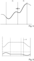
- Fig.6 shows the graphical user interface 1 of the Fig.1 shown design system 100 in a so-called online mode, during which the design system 100 is in data communication with the drive system 200.
- the position is shown as a function of the master axis position, at the bottom, the speed as a function of the master axis position.
- the online mode allows the tracking of the motion profile currently being processed in the drive system 200 by means of a marker 9, which automatically follows the master axis position (X-axis) in online mode.
- the marker 9 is displayed using the ruler function included in the editor.
- the marker or ruler 9 follows the master position in automatic mode and it is displayed whether the curve or the displayed
- the motion profile also corresponds exactly to the curve or motion profile that is being implemented in the drive system.
- the online mode is usually helpful during commissioning when the master axis or the master signal is moving slowly. This is the case when adjusting and testing a machine. It is possible to visually check which curve data is currently being executed.
- the existing ruler function is expanded to include an additional mode.
- the ruler can be active, inactive or in automatic mode.
- automatic mode the ruler follows the master position. There is only one ruler displayed at a time. This ensures clarity and comprehensibility for the user.
- the ruler on/off switch in the editor's toolbar (upper part of the screen, see 6th button from the left with a blue icon in the figure below) has an additional 3rd switch state, which corresponds to the active automatic mode. This can only be switched when the editor is in online mode, i.e. the programming environment is connected to the device.
Landscapes
- Engineering & Computer Science (AREA)
- Physics & Mathematics (AREA)
- General Physics & Mathematics (AREA)
- Geometry (AREA)
- Human Computer Interaction (AREA)
- Manufacturing & Machinery (AREA)
- Automation & Control Theory (AREA)
- Theoretical Computer Science (AREA)
- Mathematical Analysis (AREA)
- Mathematical Optimization (AREA)
- Pure & Applied Mathematics (AREA)
- Computer Hardware Design (AREA)
- Evolutionary Computation (AREA)
- General Engineering & Computer Science (AREA)
- Computational Mathematics (AREA)
- User Interface Of Digital Computer (AREA)
- Processing Or Creating Images (AREA)
Claims (4)
- Système de conception assistée par ordinateur (100) pour un système d'entraînement électrique (200), présentant :- un éditeur de came avec une interface utilisateur graphique (1), l'interface utilisateur graphique (1) étant configurée pour ajuster des valeurs de paramètres d'un profil de mouvement (2) du système d'entraînement électrique (200) sur la base d'entrées d'utilisateur,- une mémoire de valeurs limites (3), qui est configurée pour stocker des valeurs limites (8) du profil de mouvement (2), et- un système de surveillance de valeur limite (4), qui est configuré pour surveiller si une valeur d'un paramètre entrée au moyen d'une entrée d'utilisateur fait qu'une ou plusieurs des valeurs limites stockées (8) sont violées par le profil de mouvement résultant (2), et dans le cas où une ou plusieurs des valeurs limites stockées (8) sont violées par le profil de mouvement résultant (2), pour ajuster la valeur entrée du paramètre à une valeur du paramètre telle qu'aucune des valeurs limites stockées (8) n'est violée par le profil de mouvement résultant (2),- dans lequel le système de conception est configuré pour visualiser un profil de mouvement exécuté par le système d'entraînement (200), et- dans lequel le système de conception est configuré pour visualiser des écarts entre un profil de mouvement (2) projeté au moyen du système de conception et un profil de mouvement (2) exécuté par le système d'entraînement (200) sur la base du profil de mouvement projeté.
- Système de conception (100) selon la revendication 1, caractérisé en ce que- les paramètres du profil de mouvement (2) comprennent : des points d'appui du profil de mouvement (2), des coordonnées des points d'appui du profil de mouvement (2), une pente du profil de mouvement (2), une courbe du profil de mouvement (2), une zone de déplacement du profil de mouvement (2), des segments du profil de mouvement (2), des limites de segment du profil de mouvement (2), des vitesses aux limites de segment du profil de mouvement (2), des valeurs de bord de segment du profil de mouvement (2), une accélération du profil de mouvement (2), une secousse du profil de mouvement (2) et/ou des types de segments du profil de mouvement (2).
- Système de conception (100) selon la revendication 1 ou 2, caractérisé en ce que- les valeurs limites définissent une vitesse maximale, une accélération maximale, une secousse maximale, une zone de déplacement maximale, et/ou des limites de segment du profil de mouvement (2).
- Système de conception (100) selon l'une quelconque des revendications précédentes, caractérisé en ce que- l'éditeur de came est configuré pour fournir des entrées d'utilisateur au moyen desquelles des paramètres précédemment sélectionnés sont déplacés verticalement ou horizontalement, l'éditeur de came présentant un premier mode de réglage pendant lequel des paramètres précédemment sélectionnés peuvent être déplacés exclusivement horizontalement, et l'éditeur de came présentant un second mode de réglage pendant lequel des paramètres précédemment sélectionnés peuvent être déplacés exclusivement verticalement.
Applications Claiming Priority (2)
| Application Number | Priority Date | Filing Date | Title |
|---|---|---|---|
| DE102014223898.6A DE102014223898A1 (de) | 2014-11-24 | 2014-11-24 | Computerbasiertes Entwurfssystem für ein elektrisches Antriebssystem |
| PCT/EP2015/077383 WO2016083316A1 (fr) | 2014-11-24 | 2015-11-23 | Système de conception assisté par ordinateur pour système d'entraînement électrique |
Publications (2)
| Publication Number | Publication Date |
|---|---|
| EP3224748A1 EP3224748A1 (fr) | 2017-10-04 |
| EP3224748B1 true EP3224748B1 (fr) | 2024-04-10 |
Family
ID=54834791
Family Applications (1)
| Application Number | Title | Priority Date | Filing Date |
|---|---|---|---|
| EP15805411.4A Active EP3224748B1 (fr) | 2014-11-24 | 2015-11-23 | Système de conception assisté par ordinateur pour système d'entraînement électrique |
Country Status (4)
| Country | Link |
|---|---|
| US (1) | US11373017B2 (fr) |
| EP (1) | EP3224748B1 (fr) |
| DE (1) | DE102014223898A1 (fr) |
| WO (1) | WO2016083316A1 (fr) |
Families Citing this family (3)
| Publication number | Priority date | Publication date | Assignee | Title |
|---|---|---|---|---|
| DE102014223898A1 (de) * | 2014-11-24 | 2016-05-25 | Lenze Automation Gmbh | Computerbasiertes Entwurfssystem für ein elektrisches Antriebssystem |
| EP3321754B1 (fr) * | 2016-11-11 | 2020-09-09 | Siemens Aktiengesellschaft | Procédé d'optimisation de profiles de mouvement, produit-programme informatique, dispositif de commande et installation ou robot |
| CN113496063B (zh) * | 2021-07-29 | 2022-10-21 | 保定雷弗流体科技有限公司 | 挤压式蠕动泵的凸轮结构设计方法和挤压式蠕动泵 |
Family Cites Families (14)
| Publication number | Priority date | Publication date | Assignee | Title |
|---|---|---|---|---|
| US2672896A (en) * | 1952-06-30 | 1954-03-23 | Stephen B Kahn | Sawmill comprising two circular saws for cutting adjacent sides of cants simultaneously |
| US4953483A (en) * | 1989-08-04 | 1990-09-04 | Td Quilting Machinery | Automatic quilting machine and method for specialized quilting of patterns with separate computers to control the stitching and table movement functions |
| WO1992002871A1 (fr) * | 1990-08-08 | 1992-02-20 | Digital Arts Film & Television Pty. Ltd. | Systeme de commande de mouvement pour la technique cinematographique |
| US6076091A (en) * | 1997-12-09 | 2000-06-13 | International Business Machines Corporation | Method and system for providing a flexible and extensible database interactive on-line electronic catalog |
| DE10017775A1 (de) * | 2000-04-10 | 2001-10-18 | Siemens Ag | Eingabeverfahren für die Programmierung von industriellen Steuerungen |
| DE10104795B4 (de) | 2001-02-02 | 2007-07-05 | Siemens Ag | Drehzahlabhängige Sollwertkorrektur bei elektrisch geregelten Slaveantrieben |
| DE10221062A1 (de) | 2001-05-10 | 2002-12-19 | Alexandra Wolf | System und Verfahren zur Projektierung von Kurvenscheiben im Mehrachsverbund |
| US7438192B1 (en) * | 2004-05-28 | 2008-10-21 | Owens-Brockway Glass Container Inc. | Electronic control system for container indexing and inspection apparatus |
| DE102007006421A1 (de) * | 2007-02-05 | 2008-08-07 | Robert Bosch Gmbh | Verfahren zum Betreiben von gesteuerten Maschinen |
| US20160098038A1 (en) * | 2014-10-01 | 2016-04-07 | Rockwell Automation Technologies, Inc. | Sizing and selection closer to the executing environment |
| DE102014223898A1 (de) * | 2014-11-24 | 2016-05-25 | Lenze Automation Gmbh | Computerbasiertes Entwurfssystem für ein elektrisches Antriebssystem |
| EP3037903A1 (fr) * | 2014-12-22 | 2016-06-29 | Siemens Aktiengesellschaft | Procédé de fonctionnement d'un système technique, dispositif de commande, produit-programme informatique et système technique |
| DE102017008748A1 (de) * | 2017-09-19 | 2019-03-21 | Innolite Gmbh | Software-Baustein, Präzisionsmaschine, Verfahren und Bauteil |
| US10469016B1 (en) * | 2018-07-02 | 2019-11-05 | Rockwell Automation Technologies, Inc. | System and method for improving drive efficiency in an industrial automation system |
-
2014
- 2014-11-24 DE DE102014223898.6A patent/DE102014223898A1/de active Pending
-
2015
- 2015-11-23 EP EP15805411.4A patent/EP3224748B1/fr active Active
- 2015-11-23 US US15/529,380 patent/US11373017B2/en active Active
- 2015-11-23 WO PCT/EP2015/077383 patent/WO2016083316A1/fr not_active Ceased
Also Published As
| Publication number | Publication date |
|---|---|
| US11373017B2 (en) | 2022-06-28 |
| WO2016083316A1 (fr) | 2016-06-02 |
| EP3224748A1 (fr) | 2017-10-04 |
| US20170262574A1 (en) | 2017-09-14 |
| DE102014223898A1 (de) | 2016-05-25 |
Similar Documents
| Publication | Publication Date | Title |
|---|---|---|
| EP3378299B1 (fr) | Terminal agricole | |
| DE102010023854B4 (de) | Umschalt-Vorrichtungen und Verfahren zur gemeinsamen Nutzung einer Zeiger-Eingabe-Vorrichtung zwischen mehreren Computern, Speicher-Vorrichtungen und Computer System | |
| EP1656245B1 (fr) | Procede et dispositif de commande interactive d'une machine | |
| EP3224748B1 (fr) | Système de conception assisté par ordinateur pour système d'entraînement électrique | |
| DE102013015024A1 (de) | Verzahnmaschine | |
| DE102012220062A1 (de) | Einstellung mehrerer benutzereingabeparameter | |
| WO2004084165A2 (fr) | Interface utilisateur d'une machine-outil | |
| EP1701258A1 (fr) | Représentation de structures logicielles hiérarchiques | |
| DE102016103700A1 (de) | Steuerkonsole | |
| DE102016205971B4 (de) | Hydrauliksystem, Verfahren zum Parametrieren einer Steuerungselektronik einer Hydraulikkomponente und Recheneinheit zum Kompilieren eines Programmcodes für den Betrieb einer Hydraulikanlage | |
| EP3295265B1 (fr) | Module de commande d'une machine dans l'industrie alimentaire | |
| DE102020205712B4 (de) | Anzeigesteuerverfahren, vorrichtung mit einer anzeigesteuereinheit und programm | |
| EP2893409B1 (fr) | Interface utilisateur et procédé pour remédier à des dysfonctionnements d'une installation industrielle | |
| DE102014019368B4 (de) | Einrichtung zur Verwaltung und Konfiguration von Feldgeräten einer Automatisierungsanlage | |
| DE112017007918T5 (de) | Anzeigesteuerungseinrichtung, Anzeigesteuerungsverfahren, Anzeigesteuerungsprogramm und elektronische Einrichtung | |
| DE102013114199A1 (de) | Verfahren zur Bedienung von Feldgeräten | |
| DE102023105983A1 (de) | Datenverarbeitungsvorrichtung und Datenverarbeitungsverfahren | |
| DE112015006044T5 (de) | Engineering-Werkzeugprogramm und Engineering-Werkzeug | |
| DE112017007110T5 (de) | Berührungseingabebeurteilungseinrichtung, Berührungseingabebeurteilungsverfahren und Berührungseingabebeurteilungsprogramm | |
| EP2790076A1 (fr) | Procédé de commande d'une machine de production ou d'une machine-outil, programme informatique pour l'implémentation du procédé et dispositif de commande doté d'un tel programme informatique | |
| DE102012208457A1 (de) | Anzeige- und Bedienvorrichtung für eine Leitwarte | |
| DE112021007860T5 (de) | Industriemaschine und verfahren zur steuerung einer industriemaschine | |
| DE202013005733U1 (de) | System zur Projektierung oder Einrichtung einer technischen Anlage | |
| DE102014006701B4 (de) | Anzeigevorrichtung zur Anzeige einer Geräteinformation | |
| EP3268852A1 (fr) | Procédé de sélection ciblée d'éléments affichés sur un écran tactile |
Legal Events
| Date | Code | Title | Description |
|---|---|---|---|
| STAA | Information on the status of an ep patent application or granted ep patent |
Free format text: STATUS: THE INTERNATIONAL PUBLICATION HAS BEEN MADE |
|
| PUAI | Public reference made under article 153(3) epc to a published international application that has entered the european phase |
Free format text: ORIGINAL CODE: 0009012 |
|
| STAA | Information on the status of an ep patent application or granted ep patent |
Free format text: STATUS: REQUEST FOR EXAMINATION WAS MADE |
|
| 17P | Request for examination filed |
Effective date: 20170601 |
|
| AK | Designated contracting states |
Kind code of ref document: A1 Designated state(s): AL AT BE BG CH CY CZ DE DK EE ES FI FR GB GR HR HU IE IS IT LI LT LU LV MC MK MT NL NO PL PT RO RS SE SI SK SM TR |
|
| AX | Request for extension of the european patent |
Extension state: BA ME |
|
| DAV | Request for validation of the european patent (deleted) | ||
| DAX | Request for extension of the european patent (deleted) | ||
| STAA | Information on the status of an ep patent application or granted ep patent |
Free format text: STATUS: EXAMINATION IS IN PROGRESS |
|
| 17Q | First examination report despatched |
Effective date: 20210602 |
|
| REG | Reference to a national code |
Ref country code: DE Ref legal event code: R079 Free format text: PREVIOUS MAIN CLASS: G06F0017500000 Ipc: G05B0019180000 Ref document number: 502015016813 Country of ref document: DE |
|
| GRAP | Despatch of communication of intention to grant a patent |
Free format text: ORIGINAL CODE: EPIDOSNIGR1 |
|
| STAA | Information on the status of an ep patent application or granted ep patent |
Free format text: STATUS: GRANT OF PATENT IS INTENDED |
|
| RIC1 | Information provided on ipc code assigned before grant |
Ipc: G06F 111/04 20200101ALI20230925BHEP Ipc: G06F 30/17 20200101ALI20230925BHEP Ipc: G05B 19/4097 20060101ALI20230925BHEP Ipc: B23Q 5/34 20060101ALI20230925BHEP Ipc: G05B 19/18 20060101AFI20230925BHEP |
|
| INTG | Intention to grant announced |
Effective date: 20231023 |
|
| GRAS | Grant fee paid |
Free format text: ORIGINAL CODE: EPIDOSNIGR3 |
|
| GRAA | (expected) grant |
Free format text: ORIGINAL CODE: 0009210 |
|
| STAA | Information on the status of an ep patent application or granted ep patent |
Free format text: STATUS: THE PATENT HAS BEEN GRANTED |
|
| AK | Designated contracting states |
Kind code of ref document: B1 Designated state(s): AL AT BE BG CH CY CZ DE DK EE ES FI FR GB GR HR HU IE IS IT LI LT LU LV MC MK MT NL NO PL PT RO RS SE SI SK SM TR |
|
| REG | Reference to a national code |
Ref country code: GB Ref legal event code: FG4D Free format text: NOT ENGLISH |
|
| REG | Reference to a national code |
Ref country code: CH Ref legal event code: EP |
|
| REG | Reference to a national code |
Ref country code: DE Ref legal event code: R096 Ref document number: 502015016813 Country of ref document: DE |
|
| REG | Reference to a national code |
Ref country code: DE Ref legal event code: R081 Ref document number: 502015016813 Country of ref document: DE Owner name: LENZE SE, DE Free format text: FORMER OWNER: ANMELDERANGABEN UNKLAR / UNVOLLSTAENDIG, 80297 MUENCHEN, DE |
|
| REG | Reference to a national code |
Ref country code: DE Ref legal event code: R081 Ref document number: 502015016813 Country of ref document: DE Owner name: LENZE SE, DE Free format text: FORMER OWNER: LENZE AUTOMATION GMBH, 31855 AERZEN, DE |
|
| REG | Reference to a national code |
Ref country code: IE Ref legal event code: FG4D Free format text: LANGUAGE OF EP DOCUMENT: GERMAN |
|
| REG | Reference to a national code |
Ref country code: LT Ref legal event code: MG9D |
|
| REG | Reference to a national code |
Ref country code: NL Ref legal event code: MP Effective date: 20240410 |
|
| PG25 | Lapsed in a contracting state [announced via postgrant information from national office to epo] |
Ref country code: NL Free format text: LAPSE BECAUSE OF FAILURE TO SUBMIT A TRANSLATION OF THE DESCRIPTION OR TO PAY THE FEE WITHIN THE PRESCRIBED TIME-LIMIT Effective date: 20240410 |
|
| PG25 | Lapsed in a contracting state [announced via postgrant information from national office to epo] |
Ref country code: NL Free format text: LAPSE BECAUSE OF FAILURE TO SUBMIT A TRANSLATION OF THE DESCRIPTION OR TO PAY THE FEE WITHIN THE PRESCRIBED TIME-LIMIT Effective date: 20240410 |
|
| PG25 | Lapsed in a contracting state [announced via postgrant information from national office to epo] |
Ref country code: IS Free format text: LAPSE BECAUSE OF FAILURE TO SUBMIT A TRANSLATION OF THE DESCRIPTION OR TO PAY THE FEE WITHIN THE PRESCRIBED TIME-LIMIT Effective date: 20240810 |
|
| PG25 | Lapsed in a contracting state [announced via postgrant information from national office to epo] |
Ref country code: BG Free format text: LAPSE BECAUSE OF FAILURE TO SUBMIT A TRANSLATION OF THE DESCRIPTION OR TO PAY THE FEE WITHIN THE PRESCRIBED TIME-LIMIT Effective date: 20240410 |
|
| PG25 | Lapsed in a contracting state [announced via postgrant information from national office to epo] |
Ref country code: FI Free format text: LAPSE BECAUSE OF FAILURE TO SUBMIT A TRANSLATION OF THE DESCRIPTION OR TO PAY THE FEE WITHIN THE PRESCRIBED TIME-LIMIT Effective date: 20240410 Ref country code: HR Free format text: LAPSE BECAUSE OF FAILURE TO SUBMIT A TRANSLATION OF THE DESCRIPTION OR TO PAY THE FEE WITHIN THE PRESCRIBED TIME-LIMIT Effective date: 20240410 |
|
| PG25 | Lapsed in a contracting state [announced via postgrant information from national office to epo] |
Ref country code: GR Free format text: LAPSE BECAUSE OF FAILURE TO SUBMIT A TRANSLATION OF THE DESCRIPTION OR TO PAY THE FEE WITHIN THE PRESCRIBED TIME-LIMIT Effective date: 20240711 |
|
| PG25 | Lapsed in a contracting state [announced via postgrant information from national office to epo] |
Ref country code: PT Free format text: LAPSE BECAUSE OF FAILURE TO SUBMIT A TRANSLATION OF THE DESCRIPTION OR TO PAY THE FEE WITHIN THE PRESCRIBED TIME-LIMIT Effective date: 20240812 |
|
| PG25 | Lapsed in a contracting state [announced via postgrant information from national office to epo] |
Ref country code: ES Free format text: LAPSE BECAUSE OF FAILURE TO SUBMIT A TRANSLATION OF THE DESCRIPTION OR TO PAY THE FEE WITHIN THE PRESCRIBED TIME-LIMIT Effective date: 20240410 |
|
| PG25 | Lapsed in a contracting state [announced via postgrant information from national office to epo] |
Ref country code: PL Free format text: LAPSE BECAUSE OF FAILURE TO SUBMIT A TRANSLATION OF THE DESCRIPTION OR TO PAY THE FEE WITHIN THE PRESCRIBED TIME-LIMIT Effective date: 20240410 |
|
| PG25 | Lapsed in a contracting state [announced via postgrant information from national office to epo] |
Ref country code: LV Free format text: LAPSE BECAUSE OF FAILURE TO SUBMIT A TRANSLATION OF THE DESCRIPTION OR TO PAY THE FEE WITHIN THE PRESCRIBED TIME-LIMIT Effective date: 20240410 |
|
| PG25 | Lapsed in a contracting state [announced via postgrant information from national office to epo] |
Ref country code: PT Free format text: LAPSE BECAUSE OF FAILURE TO SUBMIT A TRANSLATION OF THE DESCRIPTION OR TO PAY THE FEE WITHIN THE PRESCRIBED TIME-LIMIT Effective date: 20240812 Ref country code: PL Free format text: LAPSE BECAUSE OF FAILURE TO SUBMIT A TRANSLATION OF THE DESCRIPTION OR TO PAY THE FEE WITHIN THE PRESCRIBED TIME-LIMIT Effective date: 20240410 Ref country code: NO Free format text: LAPSE BECAUSE OF FAILURE TO SUBMIT A TRANSLATION OF THE DESCRIPTION OR TO PAY THE FEE WITHIN THE PRESCRIBED TIME-LIMIT Effective date: 20240710 Ref country code: LV Free format text: LAPSE BECAUSE OF FAILURE TO SUBMIT A TRANSLATION OF THE DESCRIPTION OR TO PAY THE FEE WITHIN THE PRESCRIBED TIME-LIMIT Effective date: 20240410 Ref country code: IS Free format text: LAPSE BECAUSE OF FAILURE TO SUBMIT A TRANSLATION OF THE DESCRIPTION OR TO PAY THE FEE WITHIN THE PRESCRIBED TIME-LIMIT Effective date: 20240810 Ref country code: HR Free format text: LAPSE BECAUSE OF FAILURE TO SUBMIT A TRANSLATION OF THE DESCRIPTION OR TO PAY THE FEE WITHIN THE PRESCRIBED TIME-LIMIT Effective date: 20240410 Ref country code: GR Free format text: LAPSE BECAUSE OF FAILURE TO SUBMIT A TRANSLATION OF THE DESCRIPTION OR TO PAY THE FEE WITHIN THE PRESCRIBED TIME-LIMIT Effective date: 20240711 Ref country code: FI Free format text: LAPSE BECAUSE OF FAILURE TO SUBMIT A TRANSLATION OF THE DESCRIPTION OR TO PAY THE FEE WITHIN THE PRESCRIBED TIME-LIMIT Effective date: 20240410 Ref country code: ES Free format text: LAPSE BECAUSE OF FAILURE TO SUBMIT A TRANSLATION OF THE DESCRIPTION OR TO PAY THE FEE WITHIN THE PRESCRIBED TIME-LIMIT Effective date: 20240410 Ref country code: BG Free format text: LAPSE BECAUSE OF FAILURE TO SUBMIT A TRANSLATION OF THE DESCRIPTION OR TO PAY THE FEE WITHIN THE PRESCRIBED TIME-LIMIT Effective date: 20240410 Ref country code: RS Free format text: LAPSE BECAUSE OF FAILURE TO SUBMIT A TRANSLATION OF THE DESCRIPTION OR TO PAY THE FEE WITHIN THE PRESCRIBED TIME-LIMIT Effective date: 20240710 |
|
| REG | Reference to a national code |
Ref country code: DE Ref legal event code: R097 Ref document number: 502015016813 Country of ref document: DE |
|
| PG25 | Lapsed in a contracting state [announced via postgrant information from national office to epo] |
Ref country code: DK Free format text: LAPSE BECAUSE OF FAILURE TO SUBMIT A TRANSLATION OF THE DESCRIPTION OR TO PAY THE FEE WITHIN THE PRESCRIBED TIME-LIMIT Effective date: 20240410 |
|
| PG25 | Lapsed in a contracting state [announced via postgrant information from national office to epo] |
Ref country code: EE Free format text: LAPSE BECAUSE OF FAILURE TO SUBMIT A TRANSLATION OF THE DESCRIPTION OR TO PAY THE FEE WITHIN THE PRESCRIBED TIME-LIMIT Effective date: 20240410 |
|
| PG25 | Lapsed in a contracting state [announced via postgrant information from national office to epo] |
Ref country code: CZ Free format text: LAPSE BECAUSE OF FAILURE TO SUBMIT A TRANSLATION OF THE DESCRIPTION OR TO PAY THE FEE WITHIN THE PRESCRIBED TIME-LIMIT Effective date: 20240410 |
|
| PG25 | Lapsed in a contracting state [announced via postgrant information from national office to epo] |
Ref country code: SK Free format text: LAPSE BECAUSE OF FAILURE TO SUBMIT A TRANSLATION OF THE DESCRIPTION OR TO PAY THE FEE WITHIN THE PRESCRIBED TIME-LIMIT Effective date: 20240410 Ref country code: RO Free format text: LAPSE BECAUSE OF FAILURE TO SUBMIT A TRANSLATION OF THE DESCRIPTION OR TO PAY THE FEE WITHIN THE PRESCRIBED TIME-LIMIT Effective date: 20240410 |
|
| PG25 | Lapsed in a contracting state [announced via postgrant information from national office to epo] |
Ref country code: SM Free format text: LAPSE BECAUSE OF FAILURE TO SUBMIT A TRANSLATION OF THE DESCRIPTION OR TO PAY THE FEE WITHIN THE PRESCRIBED TIME-LIMIT Effective date: 20240410 |
|
| PG25 | Lapsed in a contracting state [announced via postgrant information from national office to epo] |
Ref country code: SM Free format text: LAPSE BECAUSE OF FAILURE TO SUBMIT A TRANSLATION OF THE DESCRIPTION OR TO PAY THE FEE WITHIN THE PRESCRIBED TIME-LIMIT Effective date: 20240410 Ref country code: SK Free format text: LAPSE BECAUSE OF FAILURE TO SUBMIT A TRANSLATION OF THE DESCRIPTION OR TO PAY THE FEE WITHIN THE PRESCRIBED TIME-LIMIT Effective date: 20240410 Ref country code: RO Free format text: LAPSE BECAUSE OF FAILURE TO SUBMIT A TRANSLATION OF THE DESCRIPTION OR TO PAY THE FEE WITHIN THE PRESCRIBED TIME-LIMIT Effective date: 20240410 Ref country code: EE Free format text: LAPSE BECAUSE OF FAILURE TO SUBMIT A TRANSLATION OF THE DESCRIPTION OR TO PAY THE FEE WITHIN THE PRESCRIBED TIME-LIMIT Effective date: 20240410 Ref country code: DK Free format text: LAPSE BECAUSE OF FAILURE TO SUBMIT A TRANSLATION OF THE DESCRIPTION OR TO PAY THE FEE WITHIN THE PRESCRIBED TIME-LIMIT Effective date: 20240410 Ref country code: CZ Free format text: LAPSE BECAUSE OF FAILURE TO SUBMIT A TRANSLATION OF THE DESCRIPTION OR TO PAY THE FEE WITHIN THE PRESCRIBED TIME-LIMIT Effective date: 20240410 |
|
| PG25 | Lapsed in a contracting state [announced via postgrant information from national office to epo] |
Ref country code: IT Free format text: LAPSE BECAUSE OF FAILURE TO SUBMIT A TRANSLATION OF THE DESCRIPTION OR TO PAY THE FEE WITHIN THE PRESCRIBED TIME-LIMIT Effective date: 20240410 |
|
| PLBE | No opposition filed within time limit |
Free format text: ORIGINAL CODE: 0009261 |
|
| STAA | Information on the status of an ep patent application or granted ep patent |
Free format text: STATUS: NO OPPOSITION FILED WITHIN TIME LIMIT |
|
| 26N | No opposition filed |
Effective date: 20250113 |
|
| PG25 | Lapsed in a contracting state [announced via postgrant information from national office to epo] |
Ref country code: SI Free format text: LAPSE BECAUSE OF FAILURE TO SUBMIT A TRANSLATION OF THE DESCRIPTION OR TO PAY THE FEE WITHIN THE PRESCRIBED TIME-LIMIT Effective date: 20240410 |
|
| REG | Reference to a national code |
Ref country code: CH Ref legal event code: PL |
|
| PG25 | Lapsed in a contracting state [announced via postgrant information from national office to epo] |
Ref country code: MC Free format text: LAPSE BECAUSE OF FAILURE TO SUBMIT A TRANSLATION OF THE DESCRIPTION OR TO PAY THE FEE WITHIN THE PRESCRIBED TIME-LIMIT Effective date: 20240410 |
|
| PG25 | Lapsed in a contracting state [announced via postgrant information from national office to epo] |
Ref country code: LU Free format text: LAPSE BECAUSE OF NON-PAYMENT OF DUE FEES Effective date: 20241123 |
|
| REG | Reference to a national code |
Ref country code: CH Ref legal event code: PL |
|
| GBPC | Gb: european patent ceased through non-payment of renewal fee |
Effective date: 20241123 |
|
| PG25 | Lapsed in a contracting state [announced via postgrant information from national office to epo] |
Ref country code: CH Free format text: LAPSE BECAUSE OF NON-PAYMENT OF DUE FEES Effective date: 20241130 |
|
| REG | Reference to a national code |
Ref country code: BE Ref legal event code: MM Effective date: 20241130 |
|
| PG25 | Lapsed in a contracting state [announced via postgrant information from national office to epo] |
Ref country code: SE Free format text: LAPSE BECAUSE OF FAILURE TO SUBMIT A TRANSLATION OF THE DESCRIPTION OR TO PAY THE FEE WITHIN THE PRESCRIBED TIME-LIMIT Effective date: 20240410 |
|
| PG25 | Lapsed in a contracting state [announced via postgrant information from national office to epo] |
Ref country code: GB Free format text: LAPSE BECAUSE OF NON-PAYMENT OF DUE FEES Effective date: 20241123 Ref country code: BE Free format text: LAPSE BECAUSE OF NON-PAYMENT OF DUE FEES Effective date: 20241130 |
|
| PG25 | Lapsed in a contracting state [announced via postgrant information from national office to epo] |
Ref country code: FR Free format text: LAPSE BECAUSE OF NON-PAYMENT OF DUE FEES Effective date: 20241130 |
|
| PG25 | Lapsed in a contracting state [announced via postgrant information from national office to epo] |
Ref country code: IE Free format text: LAPSE BECAUSE OF NON-PAYMENT OF DUE FEES Effective date: 20241123 |
|
| PGFP | Annual fee paid to national office [announced via postgrant information from national office to epo] |
Ref country code: DE Payment date: 20251118 Year of fee payment: 11 |
|
| PG25 | Lapsed in a contracting state [announced via postgrant information from national office to epo] |
Ref country code: AT Free format text: LAPSE BECAUSE OF NON-PAYMENT OF DUE FEES Effective date: 20241123 |
|
| REG | Reference to a national code |
Ref country code: AT Ref legal event code: MM01 Ref document number: 1675534 Country of ref document: AT Kind code of ref document: T Effective date: 20241123 |
|
| PG25 | Lapsed in a contracting state [announced via postgrant information from national office to epo] |
Ref country code: HU Free format text: LAPSE BECAUSE OF FAILURE TO SUBMIT A TRANSLATION OF THE DESCRIPTION OR TO PAY THE FEE WITHIN THE PRESCRIBED TIME-LIMIT; INVALID AB INITIO Effective date: 20151123 |
|
| PG25 | Lapsed in a contracting state [announced via postgrant information from national office to epo] |
Ref country code: CY Free format text: LAPSE BECAUSE OF FAILURE TO SUBMIT A TRANSLATION OF THE DESCRIPTION OR TO PAY THE FEE WITHIN THE PRESCRIBED TIME-LIMIT; INVALID AB INITIO Effective date: 20151123 |