EP3225111B1 - Einspülbehälter mit einspüldüsen - Google Patents
Einspülbehälter mit einspüldüsen Download PDFInfo
- Publication number
- EP3225111B1 EP3225111B1 EP17401022.3A EP17401022A EP3225111B1 EP 3225111 B1 EP3225111 B1 EP 3225111B1 EP 17401022 A EP17401022 A EP 17401022A EP 3225111 B1 EP3225111 B1 EP 3225111B1
- Authority
- EP
- European Patent Office
- Prior art keywords
- line
- induction
- flushing
- fresh water
- slot
- Prior art date
- Legal status (The legal status is an assumption and is not a legal conclusion. Google has not performed a legal analysis and makes no representation as to the accuracy of the status listed.)
- Active
Links
Images

Classifications
-
- A—HUMAN NECESSITIES
- A01—AGRICULTURE; FORESTRY; ANIMAL HUSBANDRY; HUNTING; TRAPPING; FISHING
- A01M—CATCHING, TRAPPING OR SCARING OF ANIMALS; APPARATUS FOR THE DESTRUCTION OF NOXIOUS ANIMALS OR NOXIOUS PLANTS
- A01M7/00—Special adaptations or arrangements of liquid-spraying apparatus for purposes covered by this subclass
- A01M7/0089—Regulating or controlling systems
- A01M7/0092—Adding active material
-
- A—HUMAN NECESSITIES
- A01—AGRICULTURE; FORESTRY; ANIMAL HUSBANDRY; HUNTING; TRAPPING; FISHING
- A01C—PLANTING; SOWING; FERTILISING
- A01C23/00—Distributing devices specially adapted for liquid manure or other fertilising liquid, including ammonia, e.g. transport tanks or sprinkling wagons
- A01C23/04—Distributing under pressure; Distributing mud; Adaptation of watering systems for fertilising-liquids
- A01C23/042—Adding fertiliser to watering systems
-
- A—HUMAN NECESSITIES
- A01—AGRICULTURE; FORESTRY; ANIMAL HUSBANDRY; HUNTING; TRAPPING; FISHING
- A01M—CATCHING, TRAPPING OR SCARING OF ANIMALS; APPARATUS FOR THE DESTRUCTION OF NOXIOUS ANIMALS OR NOXIOUS PLANTS
- A01M7/00—Special adaptations or arrangements of liquid-spraying apparatus for purposes covered by this subclass
- A01M7/0082—Undercarriages, frames, mountings, couplings, tanks
- A01M7/0085—Tanks
Definitions
- the invention relates to a induction bowl for an agricultural field sprayer according to the preamble of claim 1.
- FIG DE 10 2013 107 445 A1 Such a induction bowl and the arrangement of induction nozzles in a induction bowl are shown in FIG DE 10 2013 107 445 A1 described.
- a plurality of flushing nozzles are arranged at a distance from one another in a flushing line which is configured in an annular ring shape and is arranged in the upper region below the filling opening of the flushing container.
- This known induction bowl with induction nozzles arranged in its upper area is assigned to the liquid supply system of an agricultural field sprayer for the metered application of plant treatment agents and / or fertilizers with a spray agent tank that have been diluted with fresh water to form a spray mixture.
- the flushing line is connected to a supply line with a fresh water supply device for supplying fresh water.
- the one flushing nozzles which are arranged at a distance from one another, each have at least one outlet opening pointing at least partially downwards.
- the flushing nozzles are arranged inside the flushing tank on the flushing line, so that the respective feed line of the respective flushing nozzle is connected to the flushing line.
- the design of the respective outlet opening of the respective dispensing nozzle is not described here. From the drawing it can only be seen that the fresh water jet emerging from the respective outlet openings of the injection nozzles is directed at an angle of 45 ° obliquely to the side and down to the central area of the injection container. This arrangement is intended to generate a rotating and / or vortex-like movement of the liquid in the induction bowl.
- the invention is based on the object of creating compact flushing nozzles and their compact arrangement on a flushing line which is arranged in the upper region and below the flushing opening of a flushing container and is configured in an annular manner.
- the compact design of the flushing nozzles can be achieved in a simple manner in that the junction is part of a line section of the flushing line that is integrated into the annular flushing line and has connection elements on subregions of the annular flushing line. This results in a direct connection of the flushing nozzles directly and directly to the flushing line via the shortest possible route.
- a simple manufacture of the flushing nozzle with the branch line can be achieved in terms of manufacturing technology in that the branch line continues over the mouth opening in the direction of the underside of the housing of the flushing nozzle and is closed in the end area by a sealing plug.
- An advantageous introduction of the fresh water with an advantageous flushing of the active substance into the fresh water can be achieved in that the slot-shaped outlet opening for the introduction of the fresh water into the induction bowl is obliquely downward and obliquely at least approximately parallel to a straight line or tangent in the The induction bowl is directed downwards at an angle.
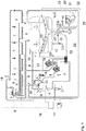
- the field sprayer has, among other things, a spray tank 1 for receiving the plant protection agent stock to be applied, a motor-driven pump 2, a control valve 4 which can be adjusted via a servomotor 3, the section switching valves 5 with the motorized adjustment members 6, which lead to the individual section lines 7 of the spray nozzles 8 equipped distributor rod leading spray line 9 on.
- This field sprayer is suitable for the metered application of plant treatment agents and / or fertilizers that have been diluted with fresh water to form a spray mixture.
- the suction line 10 On the suction side of the pump 2, the suction line 10 is connected, which with the interposition of a central switch valve 11 at the lower region of the Liquid tank 1 is connected. Further lines for the external connection of water tanks, devices for drawing in water from bodies of water, for connecting the clear water container 12 and a drain line can be connected to the switchover valve 11.
- the various return lines are combined to form a collective return line 15.
- the return line 15 opens into the liquid tank 1.
- the flow meter 18 which is connected via the signal line 16 to the electronic control and / or regulating device designed as an on-board computer 17, is arranged.
- the clear water container 12 for receiving clear water is arranged below the liquid tank 1.
- a second pump 19 is connected to this clear water tank 12.
- this second pump is connected to the switchover valve 11 via the line 20.
- the suction line 20 can optionally be connected to various liquid reservoirs, for example to the liquid tank 1, the clear water container 12 or an external liquid supply.
- the pressure line 21 is connected to the second pump 19 and is to be connected to the rinsing 22 and / or stirring system 23 when the valve positions of the field sprayer are in appropriate position.
- the field sprayer also has the induction bowl 24.
- a supply line 25, preferably designed as a fresh water supply line, for supplying fresh water is arranged on the induction bowl 24 in its upper region.
- This supply line 25 is connected to the switching valve 14 via the intermediate line 26.
- the feed line 25 is connected to the pressure line 13 of the liquid pump via this.
- the liquid pump 2 then sucks in fresh water either via line 27 from the fresh water container 12 from the liquid tank 1 or from another suitable liquid source during the flushing process Liquid for flushing in the active ingredients to be applied, which is supplied to the induction bowl 24.
- the region of the supply line opening into the induction bowl 24 is connected to the annular flushing line 28.
- flushing nozzles 29, each with a slot-shaped outlet opening 30, are arranged. The further configuration and arrangement of the flushing nozzles 29 is described below.
- a suction line 31 opening into the liquid tank 1 is connected to the lower region of the induction bowl 24.
- a motor-operated valve element 32 is assigned to this suction line 31.
- the suction line 31 is connected to the switching valve 11 via the connecting line 33 via this valve 32 or another branching device.
- the connecting line 33 can be connected to the suction line 10 leading to the pump 2 by a corresponding setting of the switching valve 11. Liquid can thus be sucked out of the induction bowl 24 via this line system.
- the induction nozzles 29 are arranged at a distance from one another on the annular in the upper region 34 below the collar 35 of the filling opening 36 of the induction bowl 24 on the flushing line 28 arranged there.
- fresh water is introduced into the induction bowl 24 for diluting the active substances to be applied.
- a plurality of flushing nozzles 29 spaced apart from one another are arranged in the flushing line 28. These flushing nozzles 29 have an outlet opening 37 pointing at least partially downwards.
- the outlet opening 37 provided in each of the dispensing nozzles 29 is designed in the manner of a slot.
- the slot-shaped course of the respective outlet opening 37 of the induction nozzles 29 is aligned at least approximately parallel to the adjacent inner wall area 38 of the induction bowl 24.
- the fresh water is supplied through a branch 39 in the underside 40 of the flushing line 28 with an adjoining branch line 41 from above to the flushing nozzle 29.
- the course of the branch line 41 becomes at least approximately 90 ° in The direction of the opposite wall 42 of the slot 43 of the outlet opening 37 is deflected and the branch line 41 opens into the induction bowl 24 via the mouth 44 of the outlet opening 37.
- the junction 39 is part of a line section of the flushing line 28 integrated into the annular flushing line 28 with connection elements 45 at partial areas 46 of the annular flushing line 28.
- the slot-shaped outlet opening 37 for introducing the fresh water into the induction bowl 24 is oblique downwards and obliquely, at least approximately parallel directed obliquely downward into a straight line or tangent drawn into the induction bowl 24 on the inner walls 38 of the container walls of the induction bowl 24.
- branch line 41 continues via the mouth opening 44 in the direction of the underside of the housing of the dispensing nozzle 29 and is closed in its end region 47 by a stopper 48.
- the flushing process of the active ingredients to be applied is carried out as follows: First, the filling line 25 is supplied with fresh water, so that fresh water is fed via the supply line 25 to the outlet openings 37 of the flushing nozzles 29, which are designed as mouth openings 44. As a result, the induction bowl 24 initially fills with fresh water.
- the active substances to be applied such as plant treatment agents and fertilizers, are filled in via the filling opening 36 of the induction bowl 24.
- These active ingredients dissolve in the liquid and are, as is commonly referred to, flushed into the liquid and reach the spray agent tank 1 via the suction line 31, so that the spray mixture to be applied is produced.
- the good and effective flushing and mixing of the active ingredients to be applied, such as pesticides, into the carrier liquid, usually fresh water, is essentially achieved by:
- the outlet openings 37 for introducing the fresh water into the induction bowl 24 are directed obliquely downward slightly against the inner wall 38 of the induction bowl 24.
- the slot-like configuration of the outlet openings 37 of the flushing nozzles 29 creates a fan-shaped water fan.
- the above-described alignment of the fresh water emerging from the mouth openings 44 of the induction nozzles 24, also referred to as carrier liquid, creates a vortex-like movement of the liquid in the induction bowl 24. This results in good dissolution and mixing of the active substance agents to be dispensed into the carrier liquid in the induction bowl 24.
- This dissolving and mixing in and mixing effect of active ingredients with the carrier liquid is achieved in that the outlet openings or from the mouths of the induction nozzles 29 are aligned in the induction bowl 24 that the fresh water flowing into the induction bowl 24 causes a rotating and / or Vortex-like movement of the liquid in the induction bowl 24 is generated.
- All the orifices of the flushing nozzles are oriented at least approximately in the same direction. This creates an effective vortex for the liquid in the induction bowl 24 in an unimpeded manner.
Landscapes
- Life Sciences & Earth Sciences (AREA)
- Engineering & Computer Science (AREA)
- Environmental Sciences (AREA)
- Insects & Arthropods (AREA)
- Pest Control & Pesticides (AREA)
- Wood Science & Technology (AREA)
- Zoology (AREA)
- Water Supply & Treatment (AREA)
- Soil Sciences (AREA)
- Catching Or Destruction (AREA)
Description
- Die Erfindung betrifft einen Einspülbehälter einer landwirtschaftlichen Feldspritze gemäß des Oberbegriffes des Patentanspruches 1.
- Ein derartiger Einspülbehälter und die Anordnung von Einspüldüsen in einem Einspülbehälter ist in
DE 10 2013 107 445 A1 beschrieben. Bei diesem bekannten Stand der Technik sind mehrere Einspüldüsen beabstandet zueinander in einer ringförmig ringförmig ausgestalteten und im oberen Bereich unterhalb der Einfüllöffnung des Einspülbehälters angeordneten Spülleitung angeordnet. Dieser bekannte Einspülbehälter mit in dessen oberen Bereich angeordneten Einspüldüsen ist dem Flüssigkeitszuführungssystem einer landwirtschaftlichen Feldspritze zum dosierten Ausbringen von mit Frischwasser zu einer Spritzbrühe verdünnten Pflanzenbehandlungsmitteln und/oder Düngemitteln mit einem Spritzmitteltank zugeordnet. Die Spülleitung ist mit einer Zuführleitung mit einer Frischwasserzuführeinrichtung zur Zuführung von Frischwasser verbunden. Die beabstandet zueinander angeordneten ein Spüldüsen weisen jeweils zumindest eine zumindest teilweise nach unten weisende Austrittsöffnung auf. Die Einspüldüsen sind innerhalb des Einspülbehälters an der Spülleitung angeordnet, so dass die jeweilige Zuleitung der jeweiligen Einspüldüse mit der Spülleitung verbunden ist. Die Ausgestaltung der jeweiligen Austrittsöffnung der jeweiligen Einspüldüse ist hier nicht beschrieben. Aus der Zeichnung ist lediglich erkennbar, dass der aus den jeweiligen Austrittsöffnungen der Einspüldüsen austretende Frischwasserstrahl im Winkel von 45° schräg zur Seite und nach unten zum Mittelbereich des Einsprülbehälters gerichtet ist. Durch diese Anordnung soll eine rotierende und/oder strudelartige Bewegung der sich im Einspülbehälter befindlichen Flüssigkeit erzeugt werden. - Der Erfindung liegt die Aufgabe zu Grunde, kompakte bauende Einspüldüsen und deren kompakte Anordnung an einer im oberen Bereich und unterhalb der Einspülöffnung eines Einspülbehälters angeordnet und ringförmig ausgestalteten Spülleitung zu schaffen.
- Diese Aufgabe wird erfindungsgemäß durch die kennzeichnenden Merkmale des Anspruches 1 gelöst.
- Infolge dieser Maßnahmen ergeben sich vorteilhaft kompakt ausgestaltete Einspüldüsen sowie deren kompakte und gedrungene Anordnung innerhalb des Einspülbehälters direkt unterhalb der von einem Kragen umgebenen Einfüllöffnung des Einspülbehälters. Durch die schlitzförmige Ausgestaltung der Austrittsöffnungen und deren erfindungsgemäße Ausrichtung wird das Frischwasser durch die schlitzförmigen Austrittsöffnungen in gerichteter Weise optimiert zum Einspülen der einzuspülenden Wirkstoffmittel in das zugeführte Frischwasser in den Einspülbehälter eingebracht. Aufgrund der entsprechenden Ausgestaltung und Anordnung der Einspüldüsen an der ringförmig ausgestalteten Spülleitung lässt sich die vorteilhafte kompakte Ausgestaltung und Anordnung von Einspüldüsen und Spülleitung erreichen.
- In einfacher Weise lässt sich die kompakte Ausgestaltung der Einspüldüsen dadurch in einfacher Weise erreichen, dass die Abzweigung Bestandteil eines in die ringförmige Spülleitung integrierten Leitungsabschnittes der Spülleitung mit Anschlusselementen an Teilbereichen der ringförmigen Spülleitung ist. Hierdurch ergibt sich ein direkter Anschluss der Einspüldüsen unmittelbar und direkt auf kürzestem Wege an die Spülleitung.
- Eine einfache Herstellung der Einspüldüse mit der Abzweigleitung lässt sich fertigungstechnisch dadurch verwirklichen, dass die Abzweigleitung sich über die Mündungsöffnung in Richtung der Unterseite des Gehäuses der Einspüldüse fortsetzt und in Endbereich durch einen Verschlußstopfen verschlossen ist.
- Eine vorteilhafte Einbringung des Frischwassers mit einer vorteilhaften Einspülung der Wirkstoffmittel in das Frischwasser lässt sich dadurch erreichen, dass die schlitzförmige Austrittsöffnung für die Einbringung des Frischwassers in den Einspülbehälter schräg nach unten und schräg zumindest annähernd parallel zu einer an den Behälter angelegten Geraden oder Tangenten in den Einspülbehälter hinein schräg nach unten gerichtet ist.
- Weitere Einzelheiten der Erfindung sind der Beispielsbeschreibung zu entnehmen. Die Zeichnungen zeigen
- Fig. 1
- den Flüssigkeitsplan einer Feldspritze in Prinzipdarstellung,
- Fig. 2
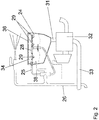
- einen Teilbereich des Flüssigkeitsplanes, betreffend den Bereich des Einspülbehäters gemäß
Fig. 1 in vergrößerter Darstellung, - Fig. 3
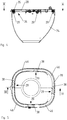
- den Einspülbehälter mit der ringförmigen Spülleitung und den daran angeordneten Einspüldüsen ohne Deckel in perspektivischer Darstellung von schräg-oben,
- Fig.4
- den Einspülbehälter gemäß
Fig.3 im Schnitt IV - IV, - Fig.5
- den Einspülbehälter gemäß
Fig.3 im Schnitt V - V, - Fig.6
- eine Einspüldüse nach
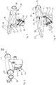
Fig.3 in perspektivischer Darstellung, - Fig.7
- die Einspüldüse nach
Fig. 6 im Schnitt VII - VII, - Fig.8
- die Einspüldüse nach
Fig. 7 im Schnitt VII - VII und - Fig.9
- die Anordnung der Einspüldüse gemäß
Fig.3 bezüglich der Innenwand des Einspülbehälters in der Ansicht IX - IX. - Die Feldspritze weist unter anderem einen Spritzmitteltank 1 zur Aufnahme der auszubringenden Pflanzenschutzmittelbrühe, eine motorisch angetriebene Pumpe 2, ein über einen Stellmotor 3 einstellbares Regelventil 4 aufweisende Dosierarmatur, die Teilbreitenschaltventile 5 mit den motorischen Einstellgliedern 6, die zu den einzelnen Teilbreitenleitungen 7 des mit Spritzdüsen 8 bestückten Verteilergestänges führende Spritzleitung 9 auf. Diese Feldspritze ist dosierten Ausbringen von mit Frischwasser zu einer Spritzbrühe verdünnten Pflanzenbehandlungsmitteln und/oder Düngemitteln geeignet.
- Auf der Saugseite der Pumpe 2 ist die Saugleitung 10 angeschlossen, die unter Zwischenschaltung eines zentralen Umschaltventils 11 am unteren Bereich des Flüssigkeitstank 1 angeschlossen ist. An dem Umschaltventil 11 können noch weitere Leitungen zum externen Anschluss von Wassertanks, Vorrichtungen zum Ansaugen von Wasser aus Gewässern, zum Anschluss des Klarwasserbehälters 12 sowie eine Ablaufleitung angeschlossen sein. Auf der Druckseite der Pumpe 2 ist eine Druckleitung 13 angeordnet, die unter Zwischenschaltung eines weiteren Umschaltventils 14 zu dem Regelventil 4 der Dosierarmatur und weiteren Einrichtungen der Feldspritze führt. Die verschiedenen Rücklaufleitungen sind zu einer Sammelrücklaufleitung 15 zusammengefasst. Die Rücklaufleitung 15 mündet in den Flüssigkeitstank 1.
- In der von den dem Regelventil 4 zu den Teilbreitenleitungen 7 führenden Spritzleitung 9 ist der über die Signalleitung 16 mit der als Bordcomputer 17 ausgebildeten elektronischen Steuer- und/oder Regeleinrichtung verbundene Durchflussmesser 18 angeordnet.
- Unterhalb des Flüssigkeitstanks 1 ist der Klarwasserbehälter 12 zur Aufnahme von Klarwasser angeordnet. An diesem Klarwasserbehälter 12 ist eine zweite Pumpe 19 angeschlossen. Saugseitig ist diese zweite Pumpe über die Leitung 20 mit dem Umschaltventil 11 verbunden. Hierüber kann die Saugleitung 20 wahlweise mit verschiedenen Flüssigkeitsreservoirs, beispielsweise mit dem Flüssigkeitstank 1, dem Klarwasserbehälter 12 oder einem externen Flüssigkeitsvorrat verbunden werden. Druckseitig ist an der zweiten Pumpe 19 die Druckleitung 21 angeschlossen, welche mit dem Spül- 22 und/oder Rührsystem 23 bei entsprechenden Ventilstellungen der Feldspritze zu verbinden ist.
- Die Feldspritze weist weiterhin den Einspülbehälter 24 auf. An dem Einspülbehälter 24 ist in dessen oberen Bereich eine vorzugsweise als Frischwasserzuführleitung ausgebildete Zuführleitung 25 zur Zuführung von Frischwasser angeordnet ist. Diese Zuführleitung 25 ist über die Zwischenleitung 26 an das Umschaltventil 14 angeschlossen. Hierüber ist die Zuführleitung 25 an die Druckleitung 13 der Flüssigkeitspumpe angeschlossen. Durch die entsprechende Einstellung des Umschaltventils 11 saugt dann bei dem Einspülvorgang die Flüssigkeitspumpe 2 entweder Frischwasser über die Leitung 27 aus dem Frischwasserbehälter 12 aus dem Flüssigkeitstank 1 oder aus einer anderen geeigneten Flüssigkeitsquelle, die Flüssigkeit zum Einspülen der auszubringenden Wirkstoffe, die dem Einspülbehälter 24 zugeführt wird, an. Der in den Einspülbehälter 24 ausmündende Bereich der Zuführleitung ist an die ringförmig ausgebildete Spülleitung 28 angeschlossen. In der Spülleitung 28 sind Einspüldüsen 29 mit jeweils einer schlitzförmigen Austrittsöffnung 30 angeordnet. Die weitere Ausgestaltung und Anordnung der Einspüldüsen 29 wird weiter unten beschrieben.
- An den unteren Bereich des Einspülbehälters 24 ist eine in dem Flüssigkeitstank 1 einmündende Saugleitung 31 angeschlossen. Dieser Saugleitung 31 ist ein motorisch zu betätigendes Ventilelement 32 zugeordnet. Über dieses Ventil 32 oder eine andere Abzweigeinrichtung ist die Saugleitung 31 mit dem Umschaltventil 11 über die Verbindungsleitung 33 verbunden. Hierdurch kann durch eine entsprechende Einstellung des Umschaltventils 11 die Verbindungsleitung 33 mit der zu der Pumpe 2 führenden Saugleitung 10 verbunden werden. Somit kann über dieses Leitungssystem Flüssigkeit aus dem Einspülbehälter 24 abgesaugt werden.
- Die Einspüldüsen 29 sind beabstandet zueinander an der ringförmig im oberen Bereich 34 unterhalb des Kragens 35 der Einfüllöffnung 36 des Einspülbehälters 24 an der dort angeordneten Spülleitung 28 angeordnet. Mittels den Einspüldüsen 29 des Einspülbehälters 24 der landwirtschaftlichen Feldspritze wird Frischwasser zum Verdünnen von auszubringenden Wirkstoffe Mitteln in den Einspülbehälter 24 eingeleitet. In der Spülleitung 28 sind mehrere zueinander beabstandete Einspüldüsen 29 angeordnet. Diese Einspüldüsen 29 weisen eine zumindest teilweise nach unten weisende Austrittsöffnung 37 auf. Die in den Einspüldüsen 29 jeweils angebrachte Austrittsöffnung 37 ist schlitzartig ausgebildet. Der schlitzförmige Verlauf der jeweiligen Austrittsöffnung 37 der Einspüldüsen 29 ist zumindest anähernd parallel zur dem benachbarten Innenwandbereich 38 des Einspülbehälters 24 ausgerichtet. Die Zuführung des Frischwassers erfolgt durch eine Abzweigung 39 in der Unterseite 40 der Spülleitung 28 mit einer sich daran anschließenden Abzweigleitung 41 von oben zu der Einspüldüse 29. Im Bereich des schlitzförmigen Verlaufes der Austrittsöffnungen 37 wird der Verlauf der Abzweigleitung 41 um zumindest annähernd 90° in Richtung der gegenüberliegenden Wand 42 des Schlitzes 43 der Austrittsöffnung 37 umgelenkt und die Abzweigleitung 41 mündet über die Mündung 44 der Austrittsöffnung 37 in den Einspülbehälter 24 entsprechend aus. Die Abzweigung 39 ist Bestandteil eines in die ringförmige Spülleitung 28 integrierten Leitungsabschnittes der Spülleitung 28 mit Anschlusselementen 45 an Teilbereichen 46 der ringförmigen Spülleitung 28. Die schlitzförmige Austrittsöffnung 37 für die Einbringung des Frischwassers in den Einspülbehälter 24 ist schräg nach unten und schräg, zumindest annähernd parallel zu einer an den Innenwänden 38 der Behälterwänden des Einspülbehälters 24 angelegten Geraden oder Tangenten in den Einspülbehälter 24 hinein schräg nach unten gerichtet.
- Schließlich setzt sich die Abzweigleitung 41 sich über die Mündungsöffnung 44 in Richtung der Unterseite des Gehäuses der Einspüldüse 29 fort und ist in ihren Endbereich 47 durch einen Verschlussstopfen 48 verschlossen.
- Der Einspülvorgang von den auszubringenden Wirkstoffen, wie Pflanzenbehandlungsmittel und oder Düngemittel erfolgt folgendermaßen:
Zunächst wird die Befüllleitung 25 mit Frischwasser versorgt, so dass über die Zuführleitung 25 Frischwasser den als Mündungsöffnungen 44 ausgebildeten Austrittsöffnungen 37 der Einspüldüsen 29 zugeleitet wird. Hierdurch füllt sich der Einspülbehälter 24 zunächst mit Frischwasser. - Wenn sich genügend Flüssigkeit in dem Einspülbehälter 24 befindet, werden über die Einfüllöffnung 36 des Einspülbehälters 24 die auszubringenden Wirkstoffmittel, wie Pflanzenbehandlungsmittel und Düngemittel eingefüllt. In der Flüssigkeit lösen sich diese Wirkstoffe auf, und werden so, wie landläufig bezeichnet, in die Flüssigkeit eingespült und gelangen über die Saugleitung 31 in den Spritzmitteltank 1, so dass die auszubringende Spritzbrühe entsteht.
- Das gute und wirksame Einspülen und Einmischen der auszubringenden Wirkstoffe, wie Pflanzenschutzmittel in die Trägerflüssigkeit, in der Regel Frischwasser, wird im Wesentlichen dadurch erreicht:
Die Austrittsöffnungen 37 für die Einbringung des Frischwassers in den Einspülbehälter 24 schräg nach unten leicht gegen die Innenwand 38 des Einspülbehälters 24 gerichtet. Durch die schlitzartige Ausgestaltung der Austrittsöffnungen 37 der Einspüldüsen 29 entsteht ein fächerförmiger Wasserfächer. Durch die vorbeschriebene Ausrichtung des aus den Mündungsöffnungen 44 der Einspüldüsen 24 austretenden Frischwassers, auch als Trägerflüssigkeit bezeichnet, wird eine strudelartige Bewegung der sich im Einspülbehälter 24 befindenden Flüssigkeit erzeugt. Hierdurch ergibt sich ein gutes Auflösen und Einmischen der auszubringenden Wirkstoffmittel in die Trägerflüssigkeit im Einspülbehälter 24. - Diese auflösende sowie ein- und vermischende Wirkung von Wirkstoffmitteln mit der Trägerflüssigkeit wird also dadurch erreicht, dass die Austrittsöffnungen bzw. aus Mündungen der Einspüldüsen 29 so in den Einspülbehälter 24 ausgerichtet ist, dass durch das in den Einspülbehälter 24 einströmende Frischwasser eine rotierende und/oder strudelartige Bewegung der sich im Einspülbehälter 24 befindliche Flüssigkeit erzeugt wird.
- Alle Ausmündungen der Einspüldüsen sind zumindest annähernd in die gleiche Richtung ausgerichtet. Hierdurch wird in ungehinderter Weise ein wirksamer Strudel für die sich im Einspülbehälter 24 befindliche Flüssigkeit erzeugt.
Claims (4)
- Einspülbehälter (24) einer landwirtschaftlichen Feldspritze zum dosierten Ausbringen von mit Frischwasser zu einer Spritzbrühe verdünnten Pflanzenbehandlungsmitteln und/oder Düngemitteln mit einem Spritzmitteltank (1), mit einer Einfüllöffnung (36) einer ringförmig im oberen Bereich unterhalb der Einfüllöffnung (36) des Einspülbehälters (24) angeordneten Spülleitung (28), einer mit der Spülleitung (28) verbundenen Zuführleitung (25) mit einer Frischwasserzuführeinrichtung zur Zuführung von Frischwasser, wobei mehrere zueinander beabstandete zumindest teilweise nach unten weisende Austrittsöffnungen (37) aufweisende Einspüldüsen (29) an der Spülleitung (28)angeordnet sind und die jeweilige Zuleitung (41) der jeweiligen Einspüldüse (29) mit der Spülleitung (28) verbunden ist, wobei die Leitung zur Zuführung des Frischwasser durch eine Abzweigung (41) in der Unterseite (40) der Spülleitung (28) mit einer sich daran anschließenden Abzweigleitung (41) von oben der Einspüldüse (29) zugeführt dadurch gekennzeichnet, dass die Austrittsöffnungen (37) schlitzartig ausgebildet sind und der schlitzförmige Verlauf der Austrittsöffnungen (37) der Einspüldüsen (29) zumindest anähernd parallel zu einem benachbarten Innenwandbereich (38) des Einspülbehälters (24) ausgerichtet ist, die Leitung zur Zuführung des Frischwassers im Bereich des schlitzförmigen Verlaufes der Austrittsöffnungen (37) um zumindest annähernd 90° in Richtung der gegenüberliegenden Wand (42) des Schlitzes der Austrittsöffnung (37) umgelenkt wird und über eine schlitzförmige Mündungsöffnung (44) ausmündet.
- Einspülbehälter nach Anspruch 1, dadurch gekennzeichnet, dass die Abzweigung (41) Bestandteil eines in die ringförmige Spülleitung (28) integrierten Leitungsabschnittes der Spülleitung mit Anschlusselementen (45) an Teilbereichen (46) der ringförmigen Spülleitung (28) ist.
- Einspülbehälter nach Anspruch 1, dadurch gekennzeichnet, dass die Abzweigleitung (41) sich über die Mündungsöffnung (44) in Richtung der Unterseite (40) des Gehäuses der Einspüldüse (29) fortsetzt und in Endbereich (47) durch einen Verschlussstopfen (48) verschlossen ist.
- Einspülbehälter nach zumindest einem der vorstehenden Ansprüche, dadurch gekennzeichnet, dass die schlitzförmige Austrittsöffnung (37) für die Einbringung des Frischwassers in den Einspülbehälter (24) schräg nach unten und schräg zumindest annähernd parallel zu einer an den Behälter (24) angelegten Geraden oder Tangenten in den Einspülbehälter (24) hinein schräg nach unten gerichtet ist.
Priority Applications (1)
| Application Number | Priority Date | Filing Date | Title |
|---|---|---|---|
| PL17401022T PL3225111T3 (pl) | 2016-03-10 | 2017-03-06 | Pojemnik wpłukiwany z dyszami wpłukiwanymi |
Applications Claiming Priority (1)
| Application Number | Priority Date | Filing Date | Title |
|---|---|---|---|
| DE102016104364.8A DE102016104364A1 (de) | 2016-03-10 | 2016-03-10 | Einspüldüse |
Publications (2)
| Publication Number | Publication Date |
|---|---|
| EP3225111A1 EP3225111A1 (de) | 2017-10-04 |
| EP3225111B1 true EP3225111B1 (de) | 2021-03-03 |
Family
ID=58530491
Family Applications (1)
| Application Number | Title | Priority Date | Filing Date |
|---|---|---|---|
| EP17401022.3A Active EP3225111B1 (de) | 2016-03-10 | 2017-03-06 | Einspülbehälter mit einspüldüsen |
Country Status (4)
| Country | Link |
|---|---|
| EP (1) | EP3225111B1 (de) |
| DE (1) | DE102016104364A1 (de) |
| DK (1) | DK3225111T3 (de) |
| PL (1) | PL3225111T3 (de) |
Families Citing this family (3)
| Publication number | Priority date | Publication date | Assignee | Title |
|---|---|---|---|---|
| DE102019130127B3 (de) * | 2019-11-08 | 2020-11-12 | Amazonen-Werke H. Dreyer Gmbh & Co. Kg | Verfahren zum Reinigen eines Wirkstofftanks |
| FR3125204B1 (fr) | 2021-07-16 | 2023-10-27 | Exel Ind | Dispositif d’incorporation pour pulverisateur agricole |
| DE102021208430A1 (de) * | 2021-08-04 | 2023-02-09 | BSH Hausgeräte GmbH | Wäschepflegendes Haushaltsgerät |
Family Cites Families (5)
| Publication number | Priority date | Publication date | Assignee | Title |
|---|---|---|---|---|
| US5335690A (en) * | 1993-09-15 | 1994-08-09 | Worth E Wayne | Water and fertilizer dispensing apparatus |
| US6840464B2 (en) * | 2002-10-15 | 2005-01-11 | Deere & Company | Tank rinse structure for an agricultural sprayer |
| DE602007008896D1 (de) * | 2006-07-03 | 2010-10-14 | Hardi Int As | Vorrichtung zum lösen von festen teilchen und flüssigen substanzen in einer flüssigkeit |
| DE102013107445A1 (de) | 2013-07-15 | 2015-01-15 | Amazonen-Werke H. Dreyer Gmbh & Co. Kg | Landwirtschaftliche Feldspritze |
| DE102014107039A1 (de) * | 2014-05-19 | 2015-11-19 | Amazonen-Werke H. Dreyer Gmbh & Co. Kg | Einspülbehälter für eine Feldspritze |
-
2016
- 2016-03-10 DE DE102016104364.8A patent/DE102016104364A1/de not_active Withdrawn
-
2017
- 2017-03-06 DK DK17401022.3T patent/DK3225111T3/da active
- 2017-03-06 PL PL17401022T patent/PL3225111T3/pl unknown
- 2017-03-06 EP EP17401022.3A patent/EP3225111B1/de active Active
Non-Patent Citations (1)
| Title |
|---|
| None * |
Also Published As
| Publication number | Publication date |
|---|---|
| EP3225111A1 (de) | 2017-10-04 |
| DE102016104364A1 (de) | 2017-09-14 |
| PL3225111T3 (pl) | 2021-10-18 |
| DK3225111T3 (da) | 2021-05-25 |
Similar Documents
| Publication | Publication Date | Title |
|---|---|---|
| DE60119637T2 (de) | Zerstäubungsanordnung insbesondere für die landwirtschaftliche Verwendung | |
| DE69832598T2 (de) | Verbesserte sprühanlage | |
| WO2019001939A1 (de) | Abgabeeinheit zur abgabe einer endflüssigkeit mit einem definierten endmischverhältnis | |
| DE102010023380B4 (de) | Wiederbefüllbares und selbstdosierendes Gebindesystem für Pflanzenschutzmittel mit integrierter, hydraulisch von außen angetriebener Dosierpumpe | |
| EP3991556B1 (de) | Landwirtschaftliche feldspritze und spritzvorrichtung für eine landwirtschaftliche feldspritze | |
| WO2012152758A1 (de) | Landwirtschaftliche feldspritze | |
| EP3114930B1 (de) | Spritzsystem | |
| EP1932424B1 (de) | Spritzeinrichtung | |
| EP3225111A1 (de) | Einspüldüse | |
| DE102013107445A1 (de) | Landwirtschaftliche Feldspritze | |
| DE10050875B4 (de) | Anlage zum Farbspritzen | |
| EP3991555B1 (de) | Landwirtschaftliche feldspritze und spritzvorrichtung für eine landwirtschaftliche feldspritze | |
| DE102017214783A1 (de) | Landwirtschaftliche Abgabeeinheit zur Abgabe einer Flüssigkeit | |
| EP3994982A1 (de) | Landwirtschaftliche feldspritze und spritzvorrichtung für eine landwirtschaftliche feldspritze | |
| DE60107339T2 (de) | Landwirtschafliche Feldspritze | |
| EP3424319B1 (de) | Einspülvorrichtung für eine landwirtschaftliche feldspritze | |
| WO2019174797A1 (de) | Landwirtschaftliche spritzvorrichtung | |
| DE202016101158U1 (de) | Vorrichtung zum Ausbringen einer Flüssigkeit | |
| EP3764781A1 (de) | Landwirtschaftliche spritzvorrichtung | |
| EP3403497B1 (de) | Mehrfachdüsenkörper | |
| EP3991554B1 (de) | Landwirtschaftliche feldspritze und spritzvorrichtung für eine landwirtschaftliche feldspritze | |
| DE102013107444A1 (de) | Landwirtschaftliche Feldspritze | |
| DE102005062535A1 (de) | Vorrichtung zum Versprühen von flüssigen Gemischen | |
| DE102018218490A1 (de) | Landwirtschaftliche Spritzdüseneinheit | |
| DE102007038636A1 (de) | Spritzeinrichtung zum Ausbringen von Flüssigkeiten |
Legal Events
| Date | Code | Title | Description |
|---|---|---|---|
| PUAI | Public reference made under article 153(3) epc to a published international application that has entered the european phase |
Free format text: ORIGINAL CODE: 0009012 |
|
| STAA | Information on the status of an ep patent application or granted ep patent |
Free format text: STATUS: THE APPLICATION HAS BEEN PUBLISHED |
|
| AK | Designated contracting states |
Kind code of ref document: A1 Designated state(s): AL AT BE BG CH CY CZ DE DK EE ES FI FR GB GR HR HU IE IS IT LI LT LU LV MC MK MT NL NO PL PT RO RS SE SI SK SM TR |
|
| AX | Request for extension of the european patent |
Extension state: BA ME |
|
| STAA | Information on the status of an ep patent application or granted ep patent |
Free format text: STATUS: REQUEST FOR EXAMINATION WAS MADE |
|
| 17P | Request for examination filed |
Effective date: 20180208 |
|
| RBV | Designated contracting states (corrected) |
Designated state(s): AL AT BE BG CH CY CZ DE DK EE ES FI FR GB GR HR HU IE IS IT LI LT LU LV MC MK MT NL NO PL PT RO RS SE SI SK SM TR |
|
| GRAP | Despatch of communication of intention to grant a patent |
Free format text: ORIGINAL CODE: EPIDOSNIGR1 |
|
| STAA | Information on the status of an ep patent application or granted ep patent |
Free format text: STATUS: GRANT OF PATENT IS INTENDED |
|
| INTG | Intention to grant announced |
Effective date: 20201124 |
|
| GRAS | Grant fee paid |
Free format text: ORIGINAL CODE: EPIDOSNIGR3 |
|
| GRAA | (expected) grant |
Free format text: ORIGINAL CODE: 0009210 |
|
| STAA | Information on the status of an ep patent application or granted ep patent |
Free format text: STATUS: THE PATENT HAS BEEN GRANTED |
|
| AK | Designated contracting states |
Kind code of ref document: B1 Designated state(s): AL AT BE BG CH CY CZ DE DK EE ES FI FR GB GR HR HU IE IS IT LI LT LU LV MC MK MT NL NO PL PT RO RS SE SI SK SM TR |
|
| REG | Reference to a national code |
Ref country code: GB Ref legal event code: FG4D Free format text: NOT ENGLISH |
|
| REG | Reference to a national code |
Ref country code: CH Ref legal event code: EP Ref country code: AT Ref legal event code: REF Ref document number: 1366185 Country of ref document: AT Kind code of ref document: T Effective date: 20210315 |
|
| REG | Reference to a national code |
Ref country code: DE Ref legal event code: R096 Ref document number: 502017009556 Country of ref document: DE |
|
| REG | Reference to a national code |
Ref country code: IE Ref legal event code: FG4D Free format text: LANGUAGE OF EP DOCUMENT: GERMAN |
|
| RAP4 | Party data changed (patent owner data changed or rights of a patent transferred) |
Owner name: AMAZONEN-WERK H. DREYER SE & CO. KG |
|
| REG | Reference to a national code |
Ref country code: DE Ref legal event code: R081 Ref document number: 502017009556 Country of ref document: DE Owner name: AMAZONEN-WERKE H. DREYER SE & CO. KG, DE Free format text: FORMER OWNER: AMAZONEN-WERKE H.DREYER GMBH &CO.KG, 49205 HASBERGEN, DE |
|
| RAP4 | Party data changed (patent owner data changed or rights of a patent transferred) |
Owner name: AMAZONEN-WERKE H. DREYER SE & CO. KG |
|
| REG | Reference to a national code |
Ref country code: NL Ref legal event code: FP |
|
| REG | Reference to a national code |
Ref country code: DK Ref legal event code: T3 Effective date: 20210518 |
|
| REG | Reference to a national code |
Ref country code: LT Ref legal event code: MG9D |
|
| PG25 | Lapsed in a contracting state [announced via postgrant information from national office to epo] |
Ref country code: LT Free format text: LAPSE BECAUSE OF FAILURE TO SUBMIT A TRANSLATION OF THE DESCRIPTION OR TO PAY THE FEE WITHIN THE PRESCRIBED TIME-LIMIT Effective date: 20210303 Ref country code: BG Free format text: LAPSE BECAUSE OF FAILURE TO SUBMIT A TRANSLATION OF THE DESCRIPTION OR TO PAY THE FEE WITHIN THE PRESCRIBED TIME-LIMIT Effective date: 20210603 Ref country code: NO Free format text: LAPSE BECAUSE OF FAILURE TO SUBMIT A TRANSLATION OF THE DESCRIPTION OR TO PAY THE FEE WITHIN THE PRESCRIBED TIME-LIMIT Effective date: 20210603 Ref country code: FI Free format text: LAPSE BECAUSE OF FAILURE TO SUBMIT A TRANSLATION OF THE DESCRIPTION OR TO PAY THE FEE WITHIN THE PRESCRIBED TIME-LIMIT Effective date: 20210303 Ref country code: GR Free format text: LAPSE BECAUSE OF FAILURE TO SUBMIT A TRANSLATION OF THE DESCRIPTION OR TO PAY THE FEE WITHIN THE PRESCRIBED TIME-LIMIT Effective date: 20210604 Ref country code: HR Free format text: LAPSE BECAUSE OF FAILURE TO SUBMIT A TRANSLATION OF THE DESCRIPTION OR TO PAY THE FEE WITHIN THE PRESCRIBED TIME-LIMIT Effective date: 20210303 |
|
| PG25 | Lapsed in a contracting state [announced via postgrant information from national office to epo] |
Ref country code: LV Free format text: LAPSE BECAUSE OF FAILURE TO SUBMIT A TRANSLATION OF THE DESCRIPTION OR TO PAY THE FEE WITHIN THE PRESCRIBED TIME-LIMIT Effective date: 20210303 Ref country code: RS Free format text: LAPSE BECAUSE OF FAILURE TO SUBMIT A TRANSLATION OF THE DESCRIPTION OR TO PAY THE FEE WITHIN THE PRESCRIBED TIME-LIMIT Effective date: 20210303 Ref country code: SE Free format text: LAPSE BECAUSE OF FAILURE TO SUBMIT A TRANSLATION OF THE DESCRIPTION OR TO PAY THE FEE WITHIN THE PRESCRIBED TIME-LIMIT Effective date: 20210303 |
|
| PG25 | Lapsed in a contracting state [announced via postgrant information from national office to epo] |
Ref country code: SM Free format text: LAPSE BECAUSE OF FAILURE TO SUBMIT A TRANSLATION OF THE DESCRIPTION OR TO PAY THE FEE WITHIN THE PRESCRIBED TIME-LIMIT Effective date: 20210303 Ref country code: CZ Free format text: LAPSE BECAUSE OF FAILURE TO SUBMIT A TRANSLATION OF THE DESCRIPTION OR TO PAY THE FEE WITHIN THE PRESCRIBED TIME-LIMIT Effective date: 20210303 Ref country code: EE Free format text: LAPSE BECAUSE OF FAILURE TO SUBMIT A TRANSLATION OF THE DESCRIPTION OR TO PAY THE FEE WITHIN THE PRESCRIBED TIME-LIMIT Effective date: 20210303 |
|
| REG | Reference to a national code |
Ref country code: CH Ref legal event code: PL |
|
| PG25 | Lapsed in a contracting state [announced via postgrant information from national office to epo] |
Ref country code: RO Free format text: LAPSE BECAUSE OF FAILURE TO SUBMIT A TRANSLATION OF THE DESCRIPTION OR TO PAY THE FEE WITHIN THE PRESCRIBED TIME-LIMIT Effective date: 20210303 Ref country code: SK Free format text: LAPSE BECAUSE OF FAILURE TO SUBMIT A TRANSLATION OF THE DESCRIPTION OR TO PAY THE FEE WITHIN THE PRESCRIBED TIME-LIMIT Effective date: 20210303 Ref country code: PT Free format text: LAPSE BECAUSE OF FAILURE TO SUBMIT A TRANSLATION OF THE DESCRIPTION OR TO PAY THE FEE WITHIN THE PRESCRIBED TIME-LIMIT Effective date: 20210705 Ref country code: IS Free format text: LAPSE BECAUSE OF FAILURE TO SUBMIT A TRANSLATION OF THE DESCRIPTION OR TO PAY THE FEE WITHIN THE PRESCRIBED TIME-LIMIT Effective date: 20210703 |
|
| REG | Reference to a national code |
Ref country code: DE Ref legal event code: R097 Ref document number: 502017009556 Country of ref document: DE |
|
| REG | Reference to a national code |
Ref country code: BE Ref legal event code: MM Effective date: 20210331 |
|
| PLBE | No opposition filed within time limit |
Free format text: ORIGINAL CODE: 0009261 |
|
| STAA | Information on the status of an ep patent application or granted ep patent |
Free format text: STATUS: NO OPPOSITION FILED WITHIN TIME LIMIT |
|
| PG25 | Lapsed in a contracting state [announced via postgrant information from national office to epo] |
Ref country code: IE Free format text: LAPSE BECAUSE OF NON-PAYMENT OF DUE FEES Effective date: 20210306 Ref country code: ES Free format text: LAPSE BECAUSE OF FAILURE TO SUBMIT A TRANSLATION OF THE DESCRIPTION OR TO PAY THE FEE WITHIN THE PRESCRIBED TIME-LIMIT Effective date: 20210303 Ref country code: LU Free format text: LAPSE BECAUSE OF NON-PAYMENT OF DUE FEES Effective date: 20210306 Ref country code: LI Free format text: LAPSE BECAUSE OF NON-PAYMENT OF DUE FEES Effective date: 20210331 Ref country code: MC Free format text: LAPSE BECAUSE OF FAILURE TO SUBMIT A TRANSLATION OF THE DESCRIPTION OR TO PAY THE FEE WITHIN THE PRESCRIBED TIME-LIMIT Effective date: 20210303 Ref country code: CH Free format text: LAPSE BECAUSE OF NON-PAYMENT OF DUE FEES Effective date: 20210331 Ref country code: AL Free format text: LAPSE BECAUSE OF FAILURE TO SUBMIT A TRANSLATION OF THE DESCRIPTION OR TO PAY THE FEE WITHIN THE PRESCRIBED TIME-LIMIT Effective date: 20210303 |
|
| 26N | No opposition filed |
Effective date: 20211206 |
|
| PG25 | Lapsed in a contracting state [announced via postgrant information from national office to epo] |
Ref country code: SI Free format text: LAPSE BECAUSE OF FAILURE TO SUBMIT A TRANSLATION OF THE DESCRIPTION OR TO PAY THE FEE WITHIN THE PRESCRIBED TIME-LIMIT Effective date: 20210303 |
|
| PG25 | Lapsed in a contracting state [announced via postgrant information from national office to epo] |
Ref country code: IS Free format text: LAPSE BECAUSE OF FAILURE TO SUBMIT A TRANSLATION OF THE DESCRIPTION OR TO PAY THE FEE WITHIN THE PRESCRIBED TIME-LIMIT Effective date: 20210703 |
|
| PG25 | Lapsed in a contracting state [announced via postgrant information from national office to epo] |
Ref country code: BE Free format text: LAPSE BECAUSE OF NON-PAYMENT OF DUE FEES Effective date: 20210331 |
|
| REG | Reference to a national code |
Ref country code: AT Ref legal event code: MM01 Ref document number: 1366185 Country of ref document: AT Kind code of ref document: T Effective date: 20220306 |
|
| PG25 | Lapsed in a contracting state [announced via postgrant information from national office to epo] |
Ref country code: HU Free format text: LAPSE BECAUSE OF FAILURE TO SUBMIT A TRANSLATION OF THE DESCRIPTION OR TO PAY THE FEE WITHIN THE PRESCRIBED TIME-LIMIT; INVALID AB INITIO Effective date: 20170306 |
|
| P01 | Opt-out of the competence of the unified patent court (upc) registered |
Effective date: 20230523 |
|
| PG25 | Lapsed in a contracting state [announced via postgrant information from national office to epo] |
Ref country code: CY Free format text: LAPSE BECAUSE OF FAILURE TO SUBMIT A TRANSLATION OF THE DESCRIPTION OR TO PAY THE FEE WITHIN THE PRESCRIBED TIME-LIMIT Effective date: 20210303 |
|
| PG25 | Lapsed in a contracting state [announced via postgrant information from national office to epo] |
Ref country code: AT Free format text: LAPSE BECAUSE OF NON-PAYMENT OF DUE FEES Effective date: 20220306 |
|
| PG25 | Lapsed in a contracting state [announced via postgrant information from national office to epo] |
Ref country code: MK Free format text: LAPSE BECAUSE OF FAILURE TO SUBMIT A TRANSLATION OF THE DESCRIPTION OR TO PAY THE FEE WITHIN THE PRESCRIBED TIME-LIMIT Effective date: 20210303 |
|
| PG25 | Lapsed in a contracting state [announced via postgrant information from national office to epo] |
Ref country code: TR Free format text: LAPSE BECAUSE OF FAILURE TO SUBMIT A TRANSLATION OF THE DESCRIPTION OR TO PAY THE FEE WITHIN THE PRESCRIBED TIME-LIMIT Effective date: 20210303 |
|
| PG25 | Lapsed in a contracting state [announced via postgrant information from national office to epo] |
Ref country code: MT Free format text: LAPSE BECAUSE OF FAILURE TO SUBMIT A TRANSLATION OF THE DESCRIPTION OR TO PAY THE FEE WITHIN THE PRESCRIBED TIME-LIMIT Effective date: 20210303 |
|
| PGFP | Annual fee paid to national office [announced via postgrant information from national office to epo] |
Ref country code: FR Payment date: 20251231 Year of fee payment: 10 |
|
| PGFP | Annual fee paid to national office [announced via postgrant information from national office to epo] |
Ref country code: PL Payment date: 20251212 Year of fee payment: 10 |
|
| PGFP | Annual fee paid to national office [announced via postgrant information from national office to epo] |
Ref country code: NL Payment date: 20260106 Year of fee payment: 10 |
|
| PGFP | Annual fee paid to national office [announced via postgrant information from national office to epo] |
Ref country code: GB Payment date: 20260106 Year of fee payment: 10 |
|
| PGFP | Annual fee paid to national office [announced via postgrant information from national office to epo] |
Ref country code: DE Payment date: 20260102 Year of fee payment: 10 Ref country code: DK Payment date: 20260313 Year of fee payment: 10 |
|
| PGFP | Annual fee paid to national office [announced via postgrant information from national office to epo] |
Ref country code: IT Payment date: 20260220 Year of fee payment: 10 |