EP3225510B1 - Verfahren und vorrichtungen zur steuerung eines selbst balancierten fahrzeugs zum parken - Google Patents
Verfahren und vorrichtungen zur steuerung eines selbst balancierten fahrzeugs zum parken Download PDFInfo
- Publication number
- EP3225510B1 EP3225510B1 EP16197457.1A EP16197457A EP3225510B1 EP 3225510 B1 EP3225510 B1 EP 3225510B1 EP 16197457 A EP16197457 A EP 16197457A EP 3225510 B1 EP3225510 B1 EP 3225510B1
- Authority
- EP
- European Patent Office
- Prior art keywords
- self
- balanced vehicle
- surveillance camera
- park
- camera device
- Prior art date
- Legal status (The legal status is an assumption and is not a legal conclusion. Google has not performed a legal analysis and makes no representation as to the accuracy of the status listed.)
- Active
Links
Images




Classifications
-
- H—ELECTRICITY
- H04—ELECTRIC COMMUNICATION TECHNIQUE
- H04N—PICTORIAL COMMUNICATION, e.g. TELEVISION
- H04N7/00—Television systems
- H04N7/18—Closed-circuit television [CCTV] systems, i.e. systems in which the video signal is not broadcast
-
- G—PHYSICS
- G05—CONTROLLING; REGULATING
- G05D—SYSTEMS FOR CONTROLLING OR REGULATING NON-ELECTRIC VARIABLES
- G05D1/00—Control of position, course, altitude or attitude of land, water, air or space vehicles, e.g. using automatic pilots
- G05D1/02—Control of position or course in two dimensions
- G05D1/021—Control of position or course in two dimensions specially adapted to land vehicles
- G05D1/0231—Control of position or course in two dimensions specially adapted to land vehicles using optical position detecting means
- G05D1/0246—Control of position or course in two dimensions specially adapted to land vehicles using optical position detecting means using a video camera in combination with image processing means
-
- B—PERFORMING OPERATIONS; TRANSPORTING
- B62—LAND VEHICLES FOR TRAVELLING OTHERWISE THAN ON RAILS
- B62D—MOTOR VEHICLES; TRAILERS
- B62D15/00—Steering not otherwise provided for
- B62D15/02—Steering position indicators ; Steering position determination; Steering aids
- B62D15/027—Parking aids, e.g. instruction means
- B62D15/0285—Parking performed automatically
-
- B—PERFORMING OPERATIONS; TRANSPORTING
- B60—VEHICLES IN GENERAL
- B60W—CONJOINT CONTROL OF VEHICLE SUB-UNITS OF DIFFERENT TYPE OR DIFFERENT FUNCTION; CONTROL SYSTEMS SPECIALLY ADAPTED FOR HYBRID VEHICLES; ROAD VEHICLE DRIVE CONTROL SYSTEMS FOR PURPOSES NOT RELATED TO THE CONTROL OF A PARTICULAR SUB-UNIT
- B60W30/00—Purposes of road vehicle drive control systems not related to the control of a particular sub-unit, e.g. of systems using conjoint control of vehicle sub-units
- B60W30/06—Automatic manoeuvring for parking
-
- B—PERFORMING OPERATIONS; TRANSPORTING
- B62—LAND VEHICLES FOR TRAVELLING OTHERWISE THAN ON RAILS
- B62H—CYCLE STANDS; SUPPORTS OR HOLDERS FOR PARKING OR STORING CYCLES; APPLIANCES PREVENTING OR INDICATING UNAUTHORIZED USE OR THEFT OF CYCLES; LOCKS INTEGRAL WITH CYCLES; DEVICES FOR LEARNING TO RIDE CYCLES
- B62H3/00—Separate supports or holders for parking or storing cycles
-
- B—PERFORMING OPERATIONS; TRANSPORTING
- B62—LAND VEHICLES FOR TRAVELLING OTHERWISE THAN ON RAILS
- B62K—CYCLES; CYCLE FRAMES; CYCLE STEERING DEVICES; RIDER-OPERATED TERMINAL CONTROLS SPECIALLY ADAPTED FOR CYCLES; CYCLE AXLE SUSPENSIONS; CYCLE SIDECARS, FORECARS, OR THE LIKE
- B62K11/00—Motorcycles, engine-assisted cycles or motor scooters with one or two wheels
- B62K11/007—Automatic balancing machines with single main ground engaging wheel or coaxial wheels supporting a rider
-
- G—PHYSICS
- G05—CONTROLLING; REGULATING
- G05D—SYSTEMS FOR CONTROLLING OR REGULATING NON-ELECTRIC VARIABLES
- G05D1/00—Control of position, course, altitude or attitude of land, water, air or space vehicles, e.g. using automatic pilots
- G05D1/0011—Control of position, course, altitude or attitude of land, water, air or space vehicles, e.g. using automatic pilots associated with a remote control arrangement
-
- G—PHYSICS
- G05—CONTROLLING; REGULATING
- G05D—SYSTEMS FOR CONTROLLING OR REGULATING NON-ELECTRIC VARIABLES
- G05D1/00—Control of position, course, altitude or attitude of land, water, air or space vehicles, e.g. using automatic pilots
- G05D1/02—Control of position or course in two dimensions
- G05D1/021—Control of position or course in two dimensions specially adapted to land vehicles
- G05D1/0276—Control of position or course in two dimensions specially adapted to land vehicles using signals provided by a source external to the vehicle
-
- G—PHYSICS
- G05—CONTROLLING; REGULATING
- G05D—SYSTEMS FOR CONTROLLING OR REGULATING NON-ELECTRIC VARIABLES
- G05D1/00—Control of position, course, altitude or attitude of land, water, air or space vehicles, e.g. using automatic pilots
- G05D1/02—Control of position or course in two dimensions
- G05D1/021—Control of position or course in two dimensions specially adapted to land vehicles
- G05D1/0276—Control of position or course in two dimensions specially adapted to land vehicles using signals provided by a source external to the vehicle
- G05D1/028—Control of position or course in two dimensions specially adapted to land vehicles using signals provided by a source external to the vehicle using a RF signal
- G05D1/0282—Control of position or course in two dimensions specially adapted to land vehicles using signals provided by a source external to the vehicle using a RF signal generated in a local control room
-
- G—PHYSICS
- G05—CONTROLLING; REGULATING
- G05D—SYSTEMS FOR CONTROLLING OR REGULATING NON-ELECTRIC VARIABLES
- G05D1/00—Control of position, course, altitude or attitude of land, water, air or space vehicles, e.g. using automatic pilots
- G05D1/12—Target-seeking control
-
- G—PHYSICS
- G06—COMPUTING OR CALCULATING; COUNTING
- G06F—ELECTRIC DIGITAL DATA PROCESSING
- G06F21/00—Security arrangements for protecting computers, components thereof, programs or data against unauthorised activity
- G06F21/30—Authentication, i.e. establishing the identity or authorisation of security principals
- G06F21/44—Program or device authentication
-
- H—ELECTRICITY
- H04—ELECTRIC COMMUNICATION TECHNIQUE
- H04W—WIRELESS COMMUNICATION NETWORKS
- H04W4/00—Services specially adapted for wireless communication networks; Facilities therefor
- H04W4/80—Services using short range communication, e.g. near-field communication [NFC], radio-frequency identification [RFID] or low energy communication
Definitions
- the present disclosure generally relates to the field of smart transportation means, and more particularly, to methods and devices for controlling a self-balanced vehicle to park.
- a self-balanced vehicle is a newly emerged short-distance transportation means.
- the self-balanced vehicle can achieve self-balance and can travel forward/backward and turn a direction by utilizing an electrical motor and a balancing device. If the self-balanced vehicle does not operate for a while, the self-balanced vehicle can be turned off automatically, to save electrical power. When the self-balanced vehicle is turned off automatically and has nothing to lean on, the self-balanced vehicle can lose self-balance and fall down, causing physical damage to the self-balanced vehicle.
- the self-balanced vehicle can emit sound or light and the like as a warning signal when the self-balanced vehicle is turned off automatically, to prompt a user nearby to manually put the self-balanced vehicle in a proper place.
- the sound or light emitted by the self-balanced vehicle can cause interference to other people around, especially when the self-balanced vehicle is in a small space, the sound or light emitted by the self-balanced vehicle can cause noise pollution. This results in poor user experience.
- the self-balanced vehicle requires a user to assist the self-balanced vehicle to park, when there is no one around or no one can reach the self-balanced vehicle in proper time, the self-balanced vehicle will fall down.
- the document US 2014/036076 discloses a method and a device for controlling a vehicle to park corresponding with the preamble of claims 1 and 6.
- the document CN 105 116 817 discloses controlling a self-balanced vehicle in connection with a camera.
- embodiments of the present disclosure provide methods and devices for controlling a self-balanced vehicle to park, which can cause the self-balanced vehicle to automatically park when the self-balanced vehicle is turned off.
- a method for controlling a self-balanced vehicle to park which is applied on the self-balanced vehicle.
- the method includes the followings steps:
- the method Before the step of sending a message of requesting for parking assistance to a surveillance camera device for controlling the self-balanced vehicle to park, the method includes the following step:
- the method can further include the following steps:
- the step of controlling the self-balanced vehicle to travel from the current location to the target location and to park according to the parking instruction information can include:
- the method can further include the following steps:
- the method can further include the following steps:
- a method for controlling a self-balanced vehicle to park which is applied on a surveillance camera device.
- the method can include the followings steps:
- the step of determining a current location of the self-balanced vehicle can include:
- the step of determining a target location of the self-balanced vehicle can include:
- the step of determining a current location of the self-balanced vehicle can include:
- the method can further include the following steps:
- the step of determining a target location of the self-balanced vehicle can include: if the surveillance camera device searches out more than one target parking spot for the self-balanced vehicle to park, determining a target parking spot corresponding to a minimum value of the complexity degrees of controlling the self-balanced vehicle to park as the target parking spot for the self-balanced vehicle to park, and determining the target location according to the target parking spot.
- a device for controlling a self-balanced vehicle to park which is applied on the self-balanced vehicle.
- the device includes:
- the device further includes:
- the device can further include:
- the first controlling module can include:
- the device can further include:
- the device can further include:
- a device for controlling a self-balanced vehicle to park which is applied on a surveillance camera device, characterized in that the device can include:
- the location determining module can include:
- the location determining module can include:
- the location determining module can include:
- the device can further include:
- the location determining module can include: a third target-location determining sub-module configured to, if the third determining module determines that the surveillance camera device searches out more than one target parking spot for the self-balanced vehicle to park, determine a target parking spot corresponding to a minimum value of the complexity degrees of controlling the self-balanced vehicle to park as the target parking spot for the self-balanced vehicle to park, and determine the target location according to the target parking spot.
- a third target-location determining sub-module configured to, if the third determining module determines that the surveillance camera device searches out more than one target parking spot for the self-balanced vehicle to park, determine a target parking spot corresponding to a minimum value of the complexity degrees of controlling the self-balanced vehicle to park as the target parking spot for the self-balanced vehicle to park, and determine the target location according to the target parking spot.
- the self-balanced vehicle can send a message of requesting for parking assistance to a surveillance camera device that can control the self-balanced vehicle to park.
- the surveillance camera device can automatically parse parking instruction information from the first response message to control the self-balanced vehicle to travel from a current location to a target location. Therefore, it can ensure that even if no one can timely come to the location of the self-balanced vehicle, the self-balanced vehicle will not fall down. Therefore, it can solve the problem in the related art that the self-balanced vehicle requires human assistance to be parked, and it can improve the user experience of the self-balanced vehicle.
- the self-balanced vehicle can indicate its current location to the surveillance camera device by emitting a location indication signal. It can solve the problem when the self-balanced vehicle is currently located at a dim place such that the surveillance camera device cannot control the self-balanced vehicle to park. Therefore, it can improve the successful chance of controlling the self-balanced vehicle to park by the surveillance camera device.
- the self-balanced vehicle can determine whether the surveillance camera device has permission to control the self-balanced vehicle to park by searching a preset control list. Then, an inquiry message is sent to the surveillance camera device which has permission to control the self-balanced vehicle to park. It can avoid establishing short-distance communication connection with a surveillance camera device which has no permission to control the self-balanced vehicle to park. Therefore, it can improve the efficiency of parking the self-balanced vehicle.
- Fig. 1A is a flowchart illustrating a method for controlling a self-balanced vehicle to park according to an exemplary embodiment.
- Fig. 1B is a schematic diagram illustrating a method for controlling a self-balanced vehicle to park according to an exemplary embodiment. The method for controlling a self-balanced vehicle to park can be applied on the self-balanced vehicle. As shown in Fig. 1A , the method for controlling a self-balanced vehicle to park includes the following steps.
- a message of requesting for parking assistance is sent to a surveillance camera device for controlling the self-balanced vehicle to park.
- the self-balanced vehicle when the self-balanced vehicle is triggered to be turned off, since there may be no spot for the self-balanced vehicle to lean on at a current location of the self-balanced vehicle, the self-balanced vehicle can send a message of requesting for parking assistance through a communication module to a surveillance camera device for controlling the self-balanced vehicle to park.
- a first response message is received which is returned from the surveillance camera device according to the message of requesting for parking assistance.
- the first response message can carry parking instruction information.
- the parking instruction information is used for controlling the self-balanced vehicle to travel from a current location to a target location.
- the self-balanced vehicle is controlled to travel from the current location to the target location and to park according to the parking instruction information.
- a traveling route from the current location to the target location can be determined according to the parking instruction information, to control the self-balanced vehicle to travel to the target location according to the traveling route and to park.
- a surveillance camera device 120 in the ambient embodiment of a self-balanced vehicle 110, there are a surveillance camera device 120, a surveillance camera device 130 and a surveillance camera device 1N0 (where N is a natural number).
- the self-balanced vehicle 110 can select a surveillance camera device to assist itself to park according to a complexity degree of traveling to the target location that each of the surveillance camera devices provides. For example, if the surveillance camera device 120 provides the lowest complexity degree of traveling to the target location, the self-balanced vehicle 110 can determine to use the surveillance camera device 120 to assist itself to park according to the complexity degree.
- the self-balanced vehicle 110 can establish a preset type of short-distance communication connection with the surveillance camera device 120 and inquiry about whether the surveillance camera device 120 can control the current self-balanced vehicle 110 to park. If the self-balanced vehicle 110 determines that the surveillance camera device 120 can control the self-balanced vehicle 110 to park, the self-balanced vehicle 110 can send to the surveillance camera device 120 a message of requesting for parking assistance. Further, the self-balanced vehicle 110 can automatically travel to the target location and park according to the parking instruction information in the first response message returned by the surveillance camera device.
- the complexity degree indicates a complexity degree of the self-balanced vehicle travelling from the current location to the target location.
- the self-balanced vehicle when the self-balanced vehicle is required to be parked, the self-balanced vehicle can send a message of requesting for parking assistance to a surveillance camera device that can control the self-balanced vehicle to park.
- the surveillance camera device can automatically parse parking instruction information from the first response message to control the self-balanced vehicle to travel from a current location to a target location. Therefore, it can ensure that even if no one can timely come to the location of the self-balanced vehicle, the self-balanced vehicle will not fall down. Therefore, it can solve the problem in the related art that the self-balanced vehicle requires human assistance to be parked, and it can improve the user experience of the self-balanced vehicle.
- the method before the step of sending a message of requesting for parking assistance to a surveillance camera device for controlling the self-balanced vehicle to park, the method can include the following step:
- determining whether the surveillance camera device can control the self-balanced vehicle to park can include:
- the method can further include the following steps:
- the method can further include the following steps:
- the method can further include the following steps:
- the self-balanced vehicle can eliminate the need for human assistance to park the self-balanced vehicle, and only a surveillance camera device for controlling the self-balanced vehicle to park is needed.
- the self-balanced vehicle can automatically park according to the parking instruction information of the surveillance camera device. Therefore, it can ensure that the self-balanced vehicle does not fall down when being turned off.
- Fig. 2 is a flowchart illustrating a method for controlling a self-balanced vehicle to park according to a first exemplary embodiment.
- the process of automatically parking the self-balanced vehicle through the above method provided by the embodiment of the present disclosure is illustrated.
- the method for controlling a self-balanced vehicle to park includes the following steps.
- step 201 it is determined whether there is a surveillance camera device that can establish a preset type of short-distance communication connection.
- the preset type of short-distance communication connection can be determined by the communication module embedded in the self-balanced vehicle.
- the preset type can be Blue Tooth, Wireless Fidelity (WiFi), Local Area Network, ZigBee protocol, Near Field Communication (NFC) or the like.
- the self-balanced vehicle when required to be parked, it can be determined through detection whether currently there is a surveillance camera device that can establish a preset type of short-distance communication connection.
- a Blue Tooth module can be controlled to detect whether currently there is a surveillance camera device that can establish a Blue Tooth connection currently.
- step 202 If currently there is a surveillance camera device that can establish a preset type of short-distance communication connection, the process is turned to step 202, otherwise the process is turned to step 209.
- step 202 it is determined whether there is a surveillance camera device than can control the self-balanced vehicle to park. If there is a surveillance camera device than can control the self-balanced vehicle to park, the process is turned to step 203, otherwise the process is turned to step 209.
- a surveillance camera device has a permission to control the self-balanced vehicle and can determine the current location of the self-balanced vehicle and the target location for the self-balanced vehicle to park, it can be determined that the surveillance camera device can control the self-balanced vehicle to park.
- the surveillance camera device can determine the current location of the self-balanced vehicle through a surveillance image.
- the surveillance camera device can also prompt the self-balanced vehicle to emit a location indication signal, and then the surveillance camera device can determine the current location of the self-balanced vehicle according to the location indication signal. For example, when the self-balanced vehicle is currently located at a dim place and the surveillance camera device fails to acquire the current location of the self-balanced vehicle, the surveillance camera device can prompt the self-balanced vehicle to emit a location indication signal for the surveillance camera device to determine the current location of the self-balanced vehicle.
- the location indication signal can be an acoustic signal and/or an optical signal.
- the surveillance camera device can determine the target location of the self-balanced vehicle according to a surveillance image.
- the surveillance camera device after the surveillance camera device determines the current location and the target location of the self-balanced vehicle, it can be calculated a complexity degree of the self-balanced vehicle travelling from the current location to the target location. If it is determined that there is no target location for the self-balanced vehicle to park, the complexity degree can be set up to a value exceeding a preset complexity threshold, and the complexity degree is sent to the self-balanced vehicle through a response message. Then, the self-balanced vehicle can determine whether the surveillance camera device can control the self-balanced vehicle to park depending on whether the complexity degree exceeds the preset complexity threshold.
- the surveillance camera device if the complexity degree is larger than the preset complexity threshold, the surveillance camera device cannot control the self-balanced vehicle to park; if the complexity degree is smaller than the preset complexity threshold, the surveillance camera device can control the self-balanced vehicle to park.
- step 203 it is determined whether there are two or more surveillance camera devices which can control the self-balanced vehicle to park. If there are two or more surveillance camera devices which can control the self-balanced vehicle to park, the process is turned to step 204, otherwise, if there is one surveillance camera device which can control the self-balanced vehicle to park, the process is turned to step 205.
- the surveillance camera device corresponding to a minimum complexity degree of the two or more surveillance camera devices is determined as the surveillance camera device for controlling the self-balanced vehicle to park, and the process is turned to step 205.
- the self-balanced vehicle can send an inquiry message to a surveillance camera device.
- the inquiry message is used for inquiring of the surveillance camera device about whether the surveillance camera device can control the self-balanced vehicle to park.
- a second response message returned by the surveillance camera device according to the inquiry message is received.
- the complexity degree of controlling the self-balanced vehicle to park is parsed from the second response message. When the complexity degree is smaller than the preset complexity threshold, it can be determined that the surveillance camera device can control the self-balanced vehicle to park.
- the complexity degree is smaller than the preset complexity threshold, it can be determined that the corresponding surveillance camera device can control the self-balanced vehicle to park; if the complexity degree is not smaller than the preset complexity threshold, it can be determined that the corresponding surveillance camera device cannot control the self-balanced vehicle to park.
- the surveillance camera device corresponding to a minimum complexity degree of the two or more surveillance camera devices is determined as the surveillance camera device for controlling the self-balanced vehicle to park.
- a message of requesting for parking assistance is sent to the surveillance camera device that can control the self-balanced vehicle to park.
- a complexity degree of the self-balanced vehicle travelling to a target location provided by the surveillance camera device 120 is 0.3
- a complexity degree of the self-balanced vehicle travelling to a target location provided by the surveillance camera device 130 is 0.6.
- the surveillance camera device 120 can be selected to assist the self-balanced vehicle to park. Then, a message of requesting for parking assistance is sent to the surveillance camera device 120.
- a first response message is received which is returned from the surveillance camera device according to the message of requesting for parking assistance.
- the first response message can carry parking instruction information.
- the parking instruction information is used for controlling the self-balanced vehicle to travel from the current location to the target location.
- the self-balanced vehicle is controlled to travel from the current location to the target location according to the parking instruction information.
- the self-balanced vehicle is controlled to adjust posture such that the self-balanced vehicle can park at the target location.
- the current gravity center of the self-balanced vehicle may be not laid on the target parking spot.
- the self-balanced vehicle can finely adjust the current posture to lay its gravity center on the target parking spot.
- a parking assistance message is sent to a user terminal for prompting the user to assist the self-balanced vehicle to park.
- the self-balanced vehicle can also emit a prompting signal such as sound or light to prompt a user nearby to manually park the self-balanced vehicle.
- a prompting signal such as sound or light
- the self-balanced vehicle can indicate its current location to the surveillance camera device by emitting a location indication signal. It can solve the problem when the self-balanced vehicle is currently located at a dim place and the surveillance camera device cannot control the self-balanced vehicle to park. Therefore, it can improve the successful chance of controlling the self-balanced vehicle to park by the surveillance camera device. By adjusting posture, it can solve the problem that the self-balanced vehicle may fall down as its gravity center is not laid on the parking spot. Therefore, it can improve the reliability of successfully parking the self-balanced vehicle.
- Fig. 3 is a flowchart illustrating a method for controlling a self-balanced vehicle to park according to a second exemplary embodiment.
- the process of the self-balanced vehicle determining whether the surveillance camera device can control the self-balanced vehicle to park through the above method provided by the embodiment of the present disclosure is illustrated.
- the method includes the following steps.
- step 301 it is determined whether the surveillance camera device has permission to control the self-balanced vehicle to park by searching a preset control list. If the surveillance camera device has permission to control the self-balanced vehicle to park, the process is turned to step 302; otherwise the process is turned to step 305.
- the preset control list is used for recording surveillance camera devices which have permission to control the self-balanced vehicle to park.
- the self-balanced vehicle can determine by detection a surveillance camera device which can currently establish a preset type of short-distance communication connection. After that, the self-balanced vehicle can search in the preset control list to see whether the surveillance camera device which can currently establish the preset type of short-distance communication connection can control the self-balanced vehicle to park.
- the user can previously make the self-balanced vehicle as corresponding to surveillance camera devices which can control the self-balanced vehicle to park, and create the preset control list in the self-balanced vehicle.
- an inquiry message is sent to a surveillance camera device, the inquiry message for inquiring of the surveillance camera device about whether the surveillance camera device can control the self-balanced vehicle to park.
- step 303 it is received a second response message which is sent by the surveillance camera device according to the inquiry message.
- a complexity degree of controlling the self-balanced vehicle to park is parsed from the second response message, and when the complexity degree is smaller than the preset complexity threshold, it is determined that the surveillance camera device can control the self-balanced vehicle to park.
- a parking assistance message is sent to a user terminal for prompting the user to assist the self-balanced vehicle to park.
- the self-balanced vehicle can also emit a prompting signal such as sound or light to prompt a user nearby to manually park the self-balanced vehicle.
- a prompting signal such as sound or light
- the self-balanced vehicle can determine whether the surveillance camera device has permission to control the self-balanced vehicle to park by searching a preset control list. Then, an inquiry message is sent to the surveillance camera device which has permission to control the self-balanced vehicle to park. It can avoid establishing short-distance communication connection with a surveillance camera device which has no permission to control the self-balanced vehicle to park. Therefore, it can improve the efficiency of parking the self-balanced vehicle.
- Fig. 4 is a flowchart illustrating a method for controlling a self-balanced vehicle to park according to a third exemplary embodiment.
- the method for controlling a self-balanced vehicle to park can be applied on a surveillance camera device.
- the method for controlling a self-balanced vehicle to park includes the following steps.
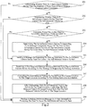
- step 401 it is received a message of requesting for parking assistance sent from a self-balanced vehicle to be parked.
- a current location of the self-balanced vehicle and a target location of the self-balanced vehicle are determined.
- an imaging apparatus of the surveillance camera device can be controlled to acquire a surveillance image presenting the self-balanced vehicle, and to process the surveillance image to determine the current location of the self-balanced vehicle.
- a signal acquiring apparatus of the surveillance camera device can be controlled to acquire the location indication signal emitted by the self-balanced vehicle, and process the acquired location indication signal to determine the current location of the self-balanced vehicle.
- the imaging apparatus of the surveillance camera device can be controlled to acquire a surveillance image presenting a target parking spot for parking the self-balanced vehicle, and process the surveillance image to determine the target location of the self-balanced vehicle.
- the target parking spot in the present disclosure can be a portion on a target object which the self-balanced vehicle can lean on (or against).
- the target object can be a wall, a cabinet with a fixed location, or other object with a temporarily fixed location which the self-balanced vehicle can lean on. It should be understood by those skilled in the art that, the specific location of the parking spot is not limited by the present disclosure.
- a surveillance camera device has permission to control the self-balanced vehicle and can determine the current location of the self-balanced vehicle and the target location for the self-balanced vehicle to lean on, it can be determined that the surveillance camera device can control the self-balanced vehicle to park.
- the location of the target parking spot is the target location for the self-balanced vehicle to park.
- if more than one target parking spot for the self-balanced vehicle to park can be determined according to the surveillance image acquired by the image capturing apparatus, complexity degrees of the self-balanced vehicle travelling to the parking spots can be calculated and a target parking spot corresponding to a minimum value of the complexity degrees can be determined as the target parking spot of the self-balanced vehicle.
- the parking spot can be also determined according to reliability of the target objects. For example, two parking spots are determined according to the surveillance image, one is a parking spot on a wall, and the other is a parking spot on a central pillar in a hall. Since it is less likely for the parking spot on the wall than for the parking spot on the central pillar in the hall to interfere with the passage of people, the parking spot on the wall can be selected as the target location of the self-balanced vehicle.
- the reliability level of the parking spots can be set up previously by the user according to experience.
- the target location of the self-balanced vehicle can be determined taking both of the reliability of the target object and the complexity degree of the self-balanced vehicle travelling to the parking spot into account.
- parking instruction information is generated according to the current location of the self-balanced vehicle and the target location of the self-balanced vehicle.
- the parking instruction information is used for control the self-balanced vehicle to travel from the current location to the target location.
- the parking instruction information can be a route for the self-balanced vehicle to travel from the current location to the target location.
- the parking instruction information can be "travel forward for 3 meters, turn left for 9 degrees and travel for 2 meters".
- a first response message is sent to the self-balanced vehicle, the first response message carrying the parking instruction information such that the self-balanced vehicle can park according to the parking instruction information.
- the surveillance camera device can accurately determine the current location and the target location of the self-balanced vehicle according to a captured surveillance image, can accurately calculate a route for the self-balanced vehicle travelling from the current location to the target location, and then can control the self-balanced vehicle to travel from the current location to the target location and park through the parking instruction information. Therefore, it can improve the reliability of automatically parking the self-balanced vehicle. It can solve the problem that the self-balanced vehicle requires human assistance to be parked, and if no one can timely come to the location of the self-balanced vehicle, the self-balanced vehicle will fall down.
- the step of determining a current location of the self-balanced vehicle can include:
- the step of determining a target location of the self-balanced vehicle can include:
- the step of determining a current location of the self-balanced vehicle can include:
- the method can further include the following steps:
- the step of determining a target location of the self-balanced vehicle can include: if the surveillance camera device searches out more than one target parking spot for the self-balanced vehicle to park, determining a target parking spot corresponding to a minimum value of the complexity degrees of controlling the self-balanced vehicle to park as the target parking spot for the self-balanced vehicle to park, and determining the target location according to the target parking spot.
- a route for the self-balanced vehicle travelling from the current location to the target location can be accurately calculated, and the self-balanced vehicle can be controlled to travel from the current location to the target location and to park according to the parking instruction information. Therefore, it can improve the reliability of automatically parking the self-balanced vehicle.
- Fig. 5 is a flowchart illustrating a method for controlling a self-balanced vehicle to park according to a fourth exemplary embodiment.
- the method for controlling a self-balanced vehicle to park can be applied on a surveillance camera device.
- the method for controlling a self-balanced vehicle to park includes the following steps.
- step 501 an inquiry message sent from the self-balanced vehicle is received.
- the inquiry message is used for inquire of the surveillance camera device about whether the surveillance camera device can control the self-balanced vehicle to park.
- a current location of the self-balanced vehicle is determined.
- the current location of the self-balanced vehicle can be determined by the following three approaches.
- the current location of the self-balanced vehicle can be determined according to the current surveillance image.
- the image capturing apparatus of the surveillance camera device can be controlled to rotate within a preset range, and stop rotating when a target surveillance image presenting the self-balanced vehicle is captured. Then, the current location of the self-balanced vehicle can be determined according to the target surveillance image.
- a location requesting message is sent to the self-balanced vehicle and the current location of the self-balanced vehicle can be determined according to a location indication signal emitted by the self-balanced vehicle.
- a signal capturing apparatus of the surveillance camera device can be controlled to capture the location indication signal.
- the location indication signal can be an acoustic signal and/or an optical signal. Then, the current location of the self-balanced vehicle can be determined according to the location indication signal emitted by the self-balanced vehicle.
- a target location for the self-balanced vehicle to park is determined.
- the target location of the self-balanced vehicle can be determined by the following three approaches.
- the target location of the self-balanced vehicle is determined according to the target parking spot in the current surveillance image.
- the image capturing apparatus of the surveillance camera device is controlled to rotate within a preset range, and to stop rotating when a target surveillance image presenting a target parking spot is captured. Then, the target location of the self-balanced vehicle is determined according to the target surveillance image.
- a complexity degree of the self-balanced vehicle travelling from the current location to the target location is determined.
- the complexity degree of travelling to the target location can be determined according a length of a route of travelling from the current location to the target location, a number of turns in the route and the like.
- a second response message is sent to the self-balanced vehicle, the second response message carrying the complexity degree of parking the self-balanced vehicle.
- step 506 it is received a message of requesting for parking assistance sent from a self-balanced vehicle to be parked.
- parking instruction information for controlling the self-balanced vehicle to travel from the current location to the target location is generated.
- a first response message is sent to the self-balanced vehicle, the first response message carrying the parking instruction information such that the self-balanced vehicle can park according to the parking instruction information.
- the present embodiment also has the following beneficial technical effects. If the surveillance camera device determines more than one parking spot for the self-balanced vehicle to park, an optimal parking spot can be determined as the target parking spot of the self-balanced vehicle according to a complexity degree of the self-balanced vehicle travelling to each of the parking spots and reliability of each of the parking spots. Therefore, it can improve the reliability of parking the self-balanced vehicle.
- the present disclosure also provides embodiments regarding devices for controlling a self-balanced vehicle to park.
- Fig. 6 is a block diagram illustrating a device for controlling a self-balanced vehicle to park according to an exemplary embodiment. The device is applied on the self-balanced vehicle. As shown in Fig. 6 , the device for controlling a self-balanced vehicle to park includes:
- Fig. 7 is a block diagram illustrating another device for controlling a self-balanced vehicle to park according to an exemplary embodiment. As shown in Fig. 7 , based on the embodiment as shown in Fig. 6 , in an embodiment, the device can further include:
- the first determining module 650 can include:
- the device can further include:
- Fig. 8 is a block diagram illustrating still another device for controlling a self-balanced vehicle to park according to an exemplary embodiment.
- the first controlling module 630 can include:
- the device can further include:
- the device can further include:
- Fig. 9 is a block diagram illustrating a device for controlling a self-balanced vehicle to park according to an exemplary embodiment.
- the device is applied on a surveillance camera device.
- the device for controlling a self-balanced vehicle to park can include:
- Fig. 10 is a block diagram illustrating another device for controlling a self-balanced vehicle to park according to an exemplary embodiment.
- the location determining module 920 can include:
- the location determining module 920 can further include:
- the location determining module 920 can further include:
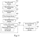
- Fig. 11 is a block diagram illustrating still another device for controlling a self-balanced vehicle to park according to an exemplary embodiment. As shown in Fig. 11 , based on the embodiment as shown in Fig. 9 , in an embodiment, the device can further include:
- the location determining module 920 can include: a third target-location determining sub-module 9293 configured to, if the third determining module 960 determines that the surveillance camera device searches out more than one target parking spot for the self-balanced vehicle to park, determine a target parking spot corresponding to a minimum value of the complexity degrees of controlling the self-balanced vehicle to park as the target parking spot for the self-balanced vehicle to park, and determine the target location according to the target parking spot.
- a third target-location determining sub-module 9293 configured to, if the third determining module 960 determines that the surveillance camera device searches out more than one target parking spot for the self-balanced vehicle to park, determine a target parking spot corresponding to a minimum value of the complexity degrees of controlling the self-balanced vehicle to park as the target parking spot for the self-balanced vehicle to park, and determine the target location according to the target parking spot.
- the device embodiments since they correspond to the method embodiments, they can refer to the related parts of the description of the method embodiments.
- the device embodiments described above are merely illustrative.
- the units described as separate may be or may not be physically separate, and the components illustrated as units may be or may not be physical units, and may be at the same location, or may be distributed to multiple units over the network.
- a part of or all of the modules can be selected to achieve the objective of the present disclosure as desired.
- One skilled in the art can understand and practice the embodiments without paying creative labor.
- Fig. 12 is a block diagram of a device for controlling a self-balanced vehicle to park according to an exemplary embodiment.
- the device according to the embodiment can be applied on a self-balanced vehicle.
- the device 1200 can include one or more of the following components: a processing component 1202, a memory 1204, a power component 1206, a multimedia component 1208, an audio component 1210, an input/output (I/O) interface 1212, a sensor component 1214, and a communication component 1216.
- a processing component 1202 a memory 1204, a power component 1206, a multimedia component 1208, an audio component 1210, an input/output (I/O) interface 1212, a sensor component 1214, and a communication component 1216.
- the processing component 1202 typically controls overall operations of the device 1200, such as the operations associated with data communications, camera operations, and recording operations.
- the processing component 1202 can include one or more processors 1220 to execute instructions to perform all or part of the steps in the above described methods.
- the processing component 1202 can include one or more modules which facilitate the interaction between the processing component 1202 and other components.
- the processing component 1202 can include a multimedia module to facilitate the interaction between the multimedia component 1208 and the processing component 1202.
- the memory 1204 is configured to store various types of data to support the operation of the device 1200. Examples of such data include instructions for any applications or methods operated on the device 1200, preset thresholds, control lists, messages, pictures, video, etc.
- the memory 1204 can be implemented using any type of volatile or non-volatile memory devices, or a combination thereof, such as a static random access memory (SRAM), an electrically erasable programmable read-only memory (EEPROM), an erasable programmable read-only memory (EPROM), a programmable read-only memory (PROM), a read-only memory (ROM), a magnetic memory, a flash memory, a magnetic or optical disk.
- SRAM static random access memory
- EEPROM electrically erasable programmable read-only memory
- EPROM erasable programmable read-only memory
- PROM programmable read-only memory
- ROM read-only memory
- magnetic memory a magnetic memory
- flash memory a flash memory
- magnetic or optical disk a
- the power component 1206 provides power to various components of the device 1200.
- the power component 1206 can include a power management system, one or more power sources, and any other components associated with the generation, management, and distribution of power in the device 1200.
- the multimedia component 1208 includes a screen providing an output interface between the device 1200 and the user.
- the screen can include a liquid crystal display (LCD) and a touch panel (TP). If the screen includes the touch panel, the screen can be implemented as a touch screen to receive input signals from the user.
- the touch panel includes one or more touch sensors to sense touches, swipes, and gestures on the touch panel. The touch sensors can not only sense a boundary of a touch or swipe action, but also sense a period of time and a pressure associated with the touch or swipe action.
- the multimedia component 1208 includes a front camera and/or a rear camera. The front camera and the rear camera can receive an external multimedia datum while the device 1200 is in an operation mode, such as a photographing mode or a video mode. Each of the front camera and the rear camera can be a fixed optical lens system or have focus and optical zoom capability.
- the audio component 1210 is configured to output and/or input audio signals.
- the audio component 1210 includes a microphone ("MIC") configured to receive an external audio signal when the device 1200 is in an operation mode, such as a call mode, a recording mode, and a voice recognition mode.
- the received audio signal can be further stored in the memory 1204 or transmitted via the communication component 1216.
- the audio component 1210 further includes a speaker to output audio signals.
- the I/O interface 1212 provides an interface between the processing component 1202 and peripheral interface modules, such as a keyboard, a click wheel, buttons, and the like.
- the buttons can include, but are not limited to, a home button, a volume button, a starting button, and a locking button.
- the sensor component 1214 includes one or more sensors to provide status assessments of various aspects of the device 1200. For instance, the sensor component 1214 can detect an open/closed status of the device 1200, relative positioning of components, e.g., the display and the keypad, of the device 1200, a change in position of the device 1200 or a component of the device 1200, a presence or absence of user contact with the device 1200, an orientation or an acceleration/deceleration of the device 1200, and a change in temperature of the device 1200.
- the sensor component 1214 can include a proximity sensor configured to detect the presence of nearby objects without any physical contact.
- the sensor component 1214 can also include a light sensor, such as a CMOS or CCD image sensor, for use in imaging applications.
- the sensor component 1214 can also include an accelerometer sensor, a gyroscope sensor, a magnetic sensor, a pressure sensor, or a temperature sensor.
- the communication component 1216 is configured to facilitate communication, wired or wirelessly, between the device 1200 and other devices.
- the device 1200 can access a wireless network based on a communication standard, such as WiFi, 2G, or 3G, or a combination thereof.
- the communication component 1216 receives a broadcast signal or broadcast associated information from an external broadcast management system via a broadcast channel.
- the communication component 1216 further includes a near field communication (NFC) module to facilitate short-range communications.
- the NFC module can be implemented based on a radio frequency identification (RFID) technology, an infrared data association (IrDA) technology, an ultra-wideband (UWB) technology, a Bluetooth (BT) technology, and other technologies.
- RFID radio frequency identification
- IrDA infrared data association
- UWB ultra-wideband
- BT Bluetooth
- the device 1200 can be implemented with one or more application specific integrated circuits (ASICs), digital signal processors (DSPs), digital signal processing devices (DSPDs), programmable logic devices (PLDs), field programmable gate arrays (FPGAs), controllers, micro-controllers, microprocessors, or other electronic components, for performing the above described methods.
- ASICs application specific integrated circuits
- DSPs digital signal processors
- DSPDs digital signal processing devices
- PLDs programmable logic devices
- FPGAs field programmable gate arrays
- controllers micro-controllers, microprocessors, or other electronic components, for performing the above described methods.
- non-transitory computer-readable storage medium including instructions, such as included in the memory 1204, executable by the processor 1220 in the device 1200, for performing the above-described methods.
- the non-transitory computer-readable storage medium can be a ROM, a RAM, a CD-ROM, a magnetic tape, a floppy disc, an optical data storage device, and the like.
- a non-transitory computer readable storage medium when instructions in the storage medium are executed by the processor of the self-balanced vehicle, the self-balanced vehicle is enabled to perform a method for controlling a self-balanced vehicle to park.
- the method includes: sending a message of requesting for parking assistance to a surveillance camera device for controlling the self-balanced vehicle to park; receiving a first response message which is returned from the surveillance camera device according to the message of requesting for parking assistance, the first response message carrying parking instruction information for controlling the self-balanced vehicle to travel from a current location to a target location; and controlling the self-balanced vehicle to travel from the current location to the target location and to park according to the parking instruction information.
- the specific structure of the surveillance camera device can refer to the block diagram as shown in Fig. 12 and corresponding description, which will not be elaborated herein.
Landscapes
- Engineering & Computer Science (AREA)
- Physics & Mathematics (AREA)
- Automation & Control Theory (AREA)
- General Physics & Mathematics (AREA)
- Mechanical Engineering (AREA)
- Aviation & Aerospace Engineering (AREA)
- Radar, Positioning & Navigation (AREA)
- Remote Sensing (AREA)
- Transportation (AREA)
- Multimedia (AREA)
- Combustion & Propulsion (AREA)
- Chemical & Material Sciences (AREA)
- Computer Security & Cryptography (AREA)
- Theoretical Computer Science (AREA)
- Signal Processing (AREA)
- Computer Vision & Pattern Recognition (AREA)
- Electromagnetism (AREA)
- Computer Hardware Design (AREA)
- Software Systems (AREA)
- General Engineering & Computer Science (AREA)
- Computer Networks & Wireless Communication (AREA)
- Traffic Control Systems (AREA)
- Closed-Circuit Television Systems (AREA)
- Studio Devices (AREA)
- Control Of Driving Devices And Active Controlling Of Vehicle (AREA)
Claims (10)
- Verfahren zur Steuerung eines selbstbalancierenden Fahrzeugs zum Parken, das auf das selbstbalancierende Fahrzeug angewendet wird, dadurch gekennzeichnet, dass das Verfahren die folgenden Schritte umfasst:Senden (101, 205) einer Nachricht zum Anfordern einer Parkunterstützung an eine Überwachungskameravorrichtung zur Steuerung des selbstbalancierenden Fahrzeugs zum Parken,Empfangen (102, 206) einer ersten Antwortnachricht, die von der Überwachungskameravorrichtung gemäß der Nachricht zum Anfordern einer Parkunterstützung zurückgesandt wird, wobei die erste Antwortnachricht Parkanweisungsinformationen zur Steuerung des selbstbalancierenden Fahrzeugs zum Fahren von einer aktuellen Position zu einer Zielposition trägt, undSteuern (103, 207) des selbstbalancierenden Fahrzeugs zum Fahren von der aktuellen Position zu der Zielposition und zum Parken gemäß den Parkanweisungsinformationen,wobei das Verfahren vor dem Schritt des Sendens einer Nachricht zum Anfordern einer Parkunterstützung an eine Überwachungskameravorrichtung zur Steuerung des selbstbalancierenden Fahrzeugs zum Parken ferner den folgenden Schritt umfasst:Bestimmen (201), ob eine Überwachungskameravorrichtung vorhanden ist, die einen voreingestellten Typ einer Kurzstreckenkommunikationsverbindung mit dem selbstbalancierenden Fahrzeug herstellen kann, undwenn eine Überwachungskameravorrichtung vorhanden ist, die einen voreingestellten Typ einer Kurzstreckenkommunikationsverbindung mit dem selbstbalancierenden Fahrzeug herstellen kann, Bestimmen (202), ob die Überwachungskameravorrichtung das selbstbalancierende Fahrzeug zum Parken steuern kann,dadurch gekennzeichnet, dass das Bestimmen, ob die Überwachungskameravorrichtung das selbstbalancierende Fahrzeug zum Parken steuern kann, umfasst:Bestimmen (301), ob die Überwachungskameravorrichtung eine Genehmigung zur Steuerung des selbstbalancierenden Fahrzeugs zum Parken aufweist, durch Durchsuchen einer voreingestellten Steuerliste zum Aufzeichnen von Überwachungskameravorrichtungen, die eine Genehmigung zur Steuerung des selbstbalancierenden Fahrzeugs zum Parken aufweisen,wenn bestimmt wird, dass die Überwachungskameravorrichtung eine Genehmigung zur Steuerung des selbstbalancierenden Fahrzeugs zum Parken aufweist, Senden (302) einer Abfragenachricht an die Überwachungskameravorrichtung, wobei die Abfragenachricht zum Abfragen der Überwachungskameravorrichtung dazu dient, ob die Überwachungskameravorrichtung das selbstbalancierende Fahrzeug zum Parken steuern kann,Empfangen (303) einer zweiten Antwortnachricht, die von der Überwachungskameravorrichtung gemäß der Abfragenachricht zurückgesandt wird,wobei die zweite Antwortnachricht einen Komplexitätsgrad der Steuerung des selbstbalancierenden Fahrzeugs zum Parken trägt, undwenn der Komplexitätsgrad kleiner als eine voreingestellte Komplexitätsschwelle ist, Bestimmen (304), dass die Überwachungskameravorrichtung das selbstbalancierende Fahrzeug zum Parken steuern kann.
- Verfahren nach Anspruch 1, dadurch gekennzeichnet, dass das Verfahren ferner die folgenden Schritte umfasst:wenn zwei oder mehr Überwachungskameravorrichtungen vorhanden sind, die eine Genehmigung zur Steuerung des selbstbalancierenden Fahrzeugs zum Parken aufweisen, Bestimmen (203) eines Komplexitätsgrads für jede von den zwei oder mehr Überwachungskameravorrichtungen,Bestimmen (204) einer Überwachungskameravorrichtung, die einem Minimalwert der Komplexitätsgrade der zwei oder mehr Überwachungskameravorrichtungen entspricht, als die Überwachungskameravorrichtung zur Steuerung des selbstbalancierenden Fahrzeugs zum Parken, und Durchführen des Schritts des Sendens einer Nachricht zum Anfordern einer Parkunterstützung an die Überwachungskameravorrichtung.
- Verfahren nach Anspruch 1, dadurch gekennzeichnet, dass der Schritt des Steuerns des selbstbalancierenden Fahrzeugs zum Fahren von der aktuellen Position zu der Zielposition und zum Parken gemäß den Parkanweisungsinformationen umfasst:Bestimmen einer Fahrstrecke von der aktuellen Position zu der Zielposition gemäß den Parkanweisungsinformationen undSteuern des selbstbalancierenden Fahrzeugs zum Fahren zu der Zielposition und zum Parken gemäß der Fahrstrecke.
- Verfahren nach Anspruch 1, dadurch gekennzeichnet, dass das Verfahren ferner die folgenden Schritte umfasst:Bestimmen (208), ob das selbstbalancierende Fahrzeug an der Zielposition angekommen ist, undnachdem bestimmt wurde, dass das selbstbalancierende Fahrzeug an der Zielposition angekommen ist, Steuern des selbstbalancierenden Fahrzeugs zum Anpassen einer Stellung, so dass das selbstbalancierende Fahrzeug an der Zielposition parken kann.
- Verfahren nach Anspruch 1, dadurch gekennzeichnet, dass das Verfahren ferner die folgenden Schritte umfasst:Bestimmen, ob eine von der Überwachungskameravorrichtung gesandte Positionsanforderungsnachricht empfangen wurde, undwenn eine von der Überwachungskameravorrichtung gesandte Positionsanforderungsnachricht empfangen wurde, Erzeugen eines Positionsangabesignals zum Angeben der aktuellen Position des selbstbalancierenden Fahrzeugs, wobei das Positionsangabesignal ein akustisches Signal und/oder ein optisches Signal ist.
- Vorrichtung zur Steuerung eines selbstbalancierenden Fahrzeugs zum Parken, die bei dem selbstbalancierenden Fahrzeug angewendet wird, dadurch gekennzeichnet, dass die Vorrichtung umfasst:ein erstes Sendemodul (610), das dazu ausgestaltet ist, eine Nachricht zum Anfordern einer Parkunterstützung an eine Überwachungskameravorrichtung zur Steuerung des selbstbalancierenden Fahrzeugs zum Parken zu senden,ein erstes Empfangsmodul (620), das dazu ausgestaltet ist, eine erste Antwortnachricht, die von der Überwachungskameravorrichtung gemäß der Nachricht zum Anfordern einer Parkunterstützung, die von dem ersten Sendemodul (610) gesandt wird, zurückgesendet wird, zu empfangen, wobei die erste Antwortnachricht Parkanweisungsinformationen zur Steuerung des selbstbalancierenden Fahrzeugs zum Fahren von einer aktuellen Position zu einer Zielposition trägt, undein erstes Steuermodul (630), das dazu ausgestaltet ist, das selbstbalancierende Fahrzeug zum Fahren von der aktuellen Position zu der Zielposition und Parken gemäß den Parkanweisungsinformationen in der ersten Antwortnachricht, die von dem ersten Empfangsmodul (620) empfangen wird, zu steuern,wobei die Vorrichtung ferner umfasst:ein Suchmodul (640), das dazu ausgestaltet ist, zu bestimmen, ob eine Überwachungskameravorrichtung vorhanden ist, die einen voreingestellten Typ einer Kurzstreckenkommunikationsverbindung mit dem selbstbalancierenden Fahrzeug herstellen kann, undein erstes Bestimmungsmodul (650),dadurch gekennzeichnet, dass das erste Bestimmungsmodul (650), das dazu ausgestaltet ist,wenn das Suchmodul (640) bestimmt, dass eine Überwachungskameravorrichtung vorhanden ist, die einen voreingestellten Typ einer Kurzstreckenkommunikationsverbindung mit dem selbstbalancierenden Fahrzeug herstellen kann, zu bestimmen, ob die Überwachungskameravorrichtung das selbstbalancierende Fahrzeug zum Parken steuern kann,wobei das erste Bestimmungsmodul (650) umfasst:ein Suchuntermodul (651), das dazu ausgestaltet ist, wenn das Suchmodul (640) bestimmt, dass eine Überwachungskameravorrichtung vorhanden ist, die einen voreingestellten Typ einer Kurzstreckenkommunikationsverbindung mit dem selbstbalancierenden Fahrzeug herstellen kann, zu bestimmen, ob die Überwachungskameravorrichtung eine Genehmigung zur Steuerung des selbstbalancierenden Fahrzeugs zum Parken aufweist, durch Durchsuchen einer voreingestellten Steuerliste zum Aufzeichnen von Überwachungskameravorrichtungen, die eine Genehmigung zur Steuerung des selbstbalancierenden Fahrzeugs zum Parken aufweisen,ein erstes Sendeuntermodul (652), das dazu ausgestaltet ist, wenn das Suchuntermodul (651) bestimmt, dass die Überwachungskameravorrichtung eine Genehmigung zur Steuerung des selbstbalancierenden Fahrzeugs zum Parken aufweist, eine Abfragenachricht an die Überwachungskameravorrichtung zu senden, wobei die Abfragenachricht dazu dient, die Überwachungskameravorrichtung abzufragen, ob die Überwachungskameravorrichtung das selbstbalancierende Fahrzeug zum Parken steuern kann,ein Empfangsuntermodul (653), das dazu ausgestaltet ist, eine zweite Antwortnachricht, die von der Überwachungskameravorrichtung gemäß der Abfragenachricht, die von dem ersten Sendeuntermodul (652) gesendet wird, zurückgesendet wird, zu empfangen, wobei die zweite Antwortnachricht einen Komplexitätsgrad der Steuerung des selbstbalancierenden Fahrzeugs zum Parken trägt, undein Parkbestimmungsuntermodul (654), das dazu ausgestaltet ist, wenn der Komplexitätsgrad, der in der zweiten Antwortnachricht getragen wird, die von dem Empfangsuntermodul (653) empfangen wird, kleiner als eine voreingestellte Komplexitätsschwelle ist, zu bestimmen, dass die Überwachungskameravorrichtung das selbstbalancierende Fahrzeug zum Parken steuern kann.
- Vorrichtung nach Anspruch 6, dadurch gekennzeichnet, dass die Vorrichtung ferner umfasst:ein Komplexitätsbestimmungsmodul (660), das dazu ausgestaltet ist, wenn das Parkbestimmungsuntermodul (654) bestimmt, dass zwei oder mehr Überwachungskameravorrichtungen vorhanden sind, die eine Genehmigung zur Steuerung des selbstbalancierenden Fahrzeugs zum Parken aufweisen, einen Komplexitätsgrad für jede von den zwei oder mehr Überwachungskameravorrichtungen zu bestimmen,ein Parkvorrichtungsbestimmungsmodul (670), das dazu ausgestaltet ist, eine Überwachungskameravorrichtung, die einem Minimalwert der Komplexitätsgrade der zwei oder mehr Überwachungskameravorrichtungen entspricht, die von dem Komplexitätsbestimmungsmodul (660) bestimmt werden, als die Überwachungskameravorrichtung zur Steuerung des selbstbalancierenden Fahrzeugs zum Parken zu bestimmen, und wobei das erste Sendemodul (610) dazu ausgestaltet ist, den Schritt des Sendens einer Nachricht zum Anfordern einer Parkunterstützung an die Überwachungskameravorrichtung durchzuführen.
- Vorrichtung nach Anspruch 6, dadurch gekennzeichnet, dass das erste Steuermodul (630) umfasst:ein Streckenbestimmungsuntermodul (631), das dazu ausgestaltet ist, eine Fahrstrecke von der aktuellen Position zu der Zielposition gemäß den Parkanweisungsinformationen in der ersten Antwortnachricht, die von dem ersten Empfangsmodul (620) empfangen wird, zu bestimmen, undein Fahruntermodul (632), das dazu ausgestaltet ist, das selbstbalancierende Fahrzeug zum Fahren zu der Zielposition und Parken gemäß der Fahrstrecke, die von dem Streckenbestimmungsuntermodul (631) bestimmt wird, zu steuern.
- Vorrichtung nach Anspruch 6, dadurch gekennzeichnet, dass die Vorrichtung ferner umfasst:ein zweites Bestimmungsmodul (680), das dazu ausgestaltet ist, zu bestimmen, ob das selbstbalancierende Fahrzeug unter der Steuerung des ersten Steuermoduls (630) an der Zielposition angekommen ist, undein zweites Steuermodul (690), das dazu ausgestaltet ist, nachdem das zweite Bestimmungsmodul (680) bestimmt hat, dass das selbstbalancierende Fahrzeug an der Zielposition angekommen ist, das selbstbalancierende Fahrzeug zum Anpassen einer Stellung zu steuern, so dass das selbstbalancierende Fahrzeug an der Zielposition parken kann.
- Vorrichtung nach Anspruch 6, dadurch gekennzeichnet, dass die Vorrichtung ferner umfasst:ein Nachrichtenbestimmungsmodul (700), das dazu ausgestaltet ist, zu bestimmen, ob eine Positionsanforderungsnachricht, die von der Überwachungskameravorrichtung gesendet wurde, empfangen wurde, undein erstes Erzeugungsmodul (710), das dazu ausgestaltet ist, wenn das Nachrichtenbestimmungsmodul (700) bestimmt, dass eine Positionsanforderungsnachricht, die von der Überwachungskameravorrichtung gesendet wurde, empfangen wurde, ein Positionsangabesignal zum Angeben der aktuellen Position des selbstbalancierenden Fahrzeugs zu erzeugen, wobei das Positionsangabesignal ein akustisches Signal und/oder ein optisches Signal ist.
Applications Claiming Priority (1)
| Application Number | Priority Date | Filing Date | Title |
|---|---|---|---|
| CN201610188056.3A CN105721834B (zh) | 2016-03-29 | 2016-03-29 | 控制平衡车停靠的方法及装置 |
Publications (2)
| Publication Number | Publication Date |
|---|---|
| EP3225510A1 EP3225510A1 (de) | 2017-10-04 |
| EP3225510B1 true EP3225510B1 (de) | 2020-09-02 |
Family
ID=56158375
Family Applications (1)
| Application Number | Title | Priority Date | Filing Date |
|---|---|---|---|
| EP16197457.1A Active EP3225510B1 (de) | 2016-03-29 | 2016-11-07 | Verfahren und vorrichtungen zur steuerung eines selbst balancierten fahrzeugs zum parken |
Country Status (4)
| Country | Link |
|---|---|
| US (1) | US10429852B2 (de) |
| EP (1) | EP3225510B1 (de) |
| CN (1) | CN105721834B (de) |
| WO (1) | WO2017166548A1 (de) |
Families Citing this family (5)
| Publication number | Priority date | Publication date | Assignee | Title |
|---|---|---|---|---|
| CN105721834B (zh) | 2016-03-29 | 2018-12-25 | 北京小米移动软件有限公司 | 控制平衡车停靠的方法及装置 |
| CN111815943B (zh) * | 2019-04-11 | 2021-09-10 | 杭州海康威视数字技术股份有限公司 | 车辆停车次数的检测方法、装置、设备及存储介质 |
| JP2021156791A (ja) * | 2020-03-27 | 2021-10-07 | トヨタ自動車株式会社 | 情報処理装置、情報処理システム、情報処理方法、及び車両 |
| CN114403114B (zh) * | 2022-01-26 | 2022-11-08 | 安徽农业大学 | 一种高地隙植保机车身姿态平衡控制系统及方法 |
| US12623554B2 (en) | 2023-09-24 | 2026-05-12 | Horwin Inc. | Self-balancing power system, self-balancing control method, self-balancing control system, and self-balancing vehicle |
Family Cites Families (45)
| Publication number | Priority date | Publication date | Assignee | Title |
|---|---|---|---|---|
| US7127413B1 (en) * | 1998-01-23 | 2006-10-24 | Toyota Jidosha Kabushiki Kaisha | Charge processing device charge processing system and charge processing card |
| US7167796B2 (en) * | 2000-03-09 | 2007-01-23 | Donnelly Corporation | Vehicle navigation system for use with a telematics system |
| US20040050611A1 (en) * | 2001-12-05 | 2004-03-18 | Deka Products Limited Partnership | Transporter storage and conveyance |
| JP4234374B2 (ja) * | 2002-08-21 | 2009-03-04 | 三菱自動車工業株式会社 | 駐車支援装置 |
| US7006901B2 (en) * | 2002-11-18 | 2006-02-28 | Wang Everett X | Computerized automated dynamic control system for single-track vehicles |
| US7230545B2 (en) * | 2003-11-07 | 2007-06-12 | Nattel Group, Inc. | Automobile communication and registry system |
| US20070083424A1 (en) * | 2005-10-07 | 2007-04-12 | Lang Darin R | Portal for secure validation of parking and integrated services |
| KR20080053835A (ko) * | 2006-12-11 | 2008-06-16 | 현대자동차주식회사 | 전방사각 감지카메라를 이용한 주차공간 인식시스템 |
| US9215781B2 (en) * | 2008-04-16 | 2015-12-15 | Avo Usa Holding 2 Corporation | Energy savings and improved security through intelligent lighting systems |
| KR101182853B1 (ko) * | 2008-12-19 | 2012-09-14 | 한국전자통신연구원 | 자동 주차 대행 시스템 및 방법 |
| WO2011039822A1 (ja) * | 2009-10-02 | 2011-04-07 | 三菱電機株式会社 | 駐車支援装置 |
| US8799037B2 (en) * | 2010-10-14 | 2014-08-05 | Palto Alto Research Center Incorporated | Computer-implemented system and method for managing motor vehicle parking reservations |
| CN102478657A (zh) * | 2010-11-23 | 2012-05-30 | 上海新世纪机器人有限公司 | 自助导航机器人系统 |
| US9581997B1 (en) * | 2011-04-22 | 2017-02-28 | Angel A. Penilla | Method and system for cloud-based communication for automatic driverless movement |
| JP5798392B2 (ja) * | 2011-06-27 | 2015-10-21 | クラリオン株式会社 | 駐車支援装置 |
| US20140350855A1 (en) * | 2012-02-28 | 2014-11-27 | Google Inc. | Systems and Methods for Providing Navigational Assistance to Reserved Parking Locations |
| US9388595B2 (en) * | 2012-07-10 | 2016-07-12 | Aqua Products, Inc. | Pool cleaning system and method to automatically clean surfaces of a pool using images from a camera |
| US8830322B2 (en) * | 2012-08-06 | 2014-09-09 | Cloudparc, Inc. | Controlling use of a single multi-vehicle parking space and a restricted location within the single multi-vehicle parking space using multiple cameras |
| US9489839B2 (en) * | 2012-08-06 | 2016-11-08 | Cloudparc, Inc. | Tracking a vehicle using an unmanned aerial vehicle |
| US9171382B2 (en) * | 2012-08-06 | 2015-10-27 | Cloudparc, Inc. | Tracking speeding violations and controlling use of parking spaces using cameras |
| CN102915638A (zh) * | 2012-10-07 | 2013-02-06 | 复旦大学 | 基于监控视频的智能停车场管理系统 |
| US9656690B2 (en) * | 2012-10-30 | 2017-05-23 | Robert Bosch Gmbh | System and method for using gestures in autonomous parking |
| PE20151254A1 (es) * | 2012-11-27 | 2015-08-31 | Cloudparc Inc | Control del uso de un solo espacio de estacionamiento multivehicular utilizando varias camaras |
| DE102013004493A1 (de) * | 2013-03-14 | 2014-09-18 | Schlauerparken Ug | Verfahren zur Anzeige von Parkplätzen |
| US9682732B2 (en) * | 2013-09-06 | 2017-06-20 | Jason Thomas Strack | Fully self-balanced hands-free portable vehicle |
| US9666075B2 (en) * | 2013-11-18 | 2017-05-30 | ImageMaker Development Inc. | Automated parking space management system with dynamically updatable display device |
| DE102014211557A1 (de) * | 2014-06-17 | 2015-12-31 | Robert Bosch Gmbh | Valet Parking Verfahren und System |
| US9805602B2 (en) * | 2014-07-21 | 2017-10-31 | Ford Global Technologies, Llc | Parking service |
| JP6067635B2 (ja) * | 2014-09-12 | 2017-01-25 | アイシン精機株式会社 | 駐車支援装置 |
| JP6129800B2 (ja) * | 2014-09-12 | 2017-05-17 | アイシン精機株式会社 | 駐車支援装置 |
| DE102014218921A1 (de) * | 2014-09-19 | 2016-03-24 | Robert Bosch Gmbh | Verfahren und Vorrichtung zum Überwachen eines automatischen Parkens eines Fahrzeugs |
| US9418553B2 (en) * | 2014-10-02 | 2016-08-16 | Omid B. Nakhjavani | Easy parking finder |
| US9639994B2 (en) * | 2014-12-29 | 2017-05-02 | Here Global B.V. | Optimized parking system |
| CN104828188B (zh) * | 2015-05-20 | 2017-03-29 | 常州爱尔威智能科技有限公司 | 电动平衡车 |
| CN104932505B (zh) * | 2015-06-08 | 2018-04-13 | 华南理工大学 | 基于摄像头检测的自动导航系统、控制方法及直立平衡车 |
| US10336318B2 (en) * | 2015-06-22 | 2019-07-02 | Ford Global Technologies, Llc | Systems and methods for vehicle park assist |
| CN105116817A (zh) * | 2015-06-26 | 2015-12-02 | 小米科技有限责任公司 | 平衡车管理方法及装置 |
| JP6544121B2 (ja) * | 2015-07-31 | 2019-07-17 | アイシン精機株式会社 | 駐車支援装置 |
| CN108349558A (zh) * | 2015-08-10 | 2018-07-31 | 北京凌云智能科技有限公司 | 自平衡载具 |
| CN105223952B (zh) * | 2015-09-28 | 2019-03-29 | 小米科技有限责任公司 | 平衡车的控制方法及装置 |
| US9758092B2 (en) * | 2015-12-15 | 2017-09-12 | Sony Corporation | System and method for generating a parking alert |
| JP6694710B2 (ja) * | 2015-12-25 | 2020-05-20 | 株式会社デンソーテン | 駐車支援装置、駐車支援方法、及び、駐車支援システム |
| US10013858B2 (en) * | 2016-02-26 | 2018-07-03 | At&T Intellectual Property I, L.P. | Notification system with haptic feedback garment and methods for use therewith |
| CN105721834B (zh) * | 2016-03-29 | 2018-12-25 | 北京小米移动软件有限公司 | 控制平衡车停靠的方法及装置 |
| CN105810007B (zh) * | 2016-03-29 | 2020-07-03 | 北京小米移动软件有限公司 | 平衡车停靠方法及装置 |
-
2016
- 2016-03-29 CN CN201610188056.3A patent/CN105721834B/zh active Active
- 2016-07-28 WO PCT/CN2016/091981 patent/WO2017166548A1/zh not_active Ceased
- 2016-11-07 EP EP16197457.1A patent/EP3225510B1/de active Active
-
2017
- 2017-01-03 US US15/397,271 patent/US10429852B2/en active Active
Non-Patent Citations (1)
| Title |
|---|
| None * |
Also Published As
| Publication number | Publication date |
|---|---|
| CN105721834A (zh) | 2016-06-29 |
| EP3225510A1 (de) | 2017-10-04 |
| CN105721834B (zh) | 2018-12-25 |
| WO2017166548A1 (zh) | 2017-10-05 |
| US20170285650A1 (en) | 2017-10-05 |
| US10429852B2 (en) | 2019-10-01 |
Similar Documents
| Publication | Publication Date | Title |
|---|---|---|
| CN104898699B (zh) | 飞行控制方法及装置、电子设备 | |
| US10336319B2 (en) | Method, device and computer-readable storage medium for parking a self-balancing vehicle | |
| EP2999313A1 (de) | Verfahren und vorrichtung zum automatisierten ansteuern eines leuchtmittels | |
| EP3128774B1 (de) | Verfahren, vorrichtungen und system zum zugriff auf ein netzwerk | |
| US20160088710A1 (en) | Method and apparatus for controlling smart light | |
| US9928725B2 (en) | Method and device for reminding user | |
| EP2985989B1 (de) | Verfahren und vorrichtung zur erfassung eines multimediadatenstroms | |
| US20170048077A1 (en) | Intelligent electric apparatus and controlling method of same | |
| US20160269527A1 (en) | Methods and apparatuses for binding with device | |
| US20160375825A1 (en) | Method and device for managing self-balancing vehicle | |
| EP3110107A1 (de) | Verfahren und vorrichtung zur verwaltung eines selbst balancierten fahrzeugs | |
| US10429852B2 (en) | Methods and devices for controlling self-balancing vehicle to park | |
| RU2641949C2 (ru) | Способ и устройство для управления интеллектуальным устройством | |
| EP3663886B1 (de) | Verfahren und vorrichtung zur steuerung eines unbemannten luftfahrzeugs, unbemanntes luftfahrzeug und fernsteuerungsvorrichtung | |
| EP3322227B1 (de) | Verfahren und vorrichtungen zur steuerung einer drahtlosen verbindung, computerprogramm und aufzeichnungsmedium | |
| CN108712736B (zh) | 寻找设备的方法、装置和系统 | |
| CN105139874A (zh) | 导航提示方法和装置 | |
| CN106228836A (zh) | 室内停车引导方法及装置 | |
| US10111026B2 (en) | Detecting method and apparatus, and storage medium | |
| CN105898228B (zh) | 用于摄像设备的控制方法及装置 | |
| CN112116803B (zh) | 信息处理方法及装置、电子设备及存储介质 | |
| CN105303891B (zh) | 一种安全驾驶方法及装置 | |
| CN106494544B (zh) | 平衡车的控制方法和装置 | |
| US20250013308A1 (en) | Control method for intelligent equipment, central control equipment and control device for intelligent equipment | |
| CN114368357A (zh) | 车辆控制方法、车辆、智能穿戴设备及可读存储介质 |
Legal Events
| Date | Code | Title | Description |
|---|---|---|---|
| PUAI | Public reference made under article 153(3) epc to a published international application that has entered the european phase |
Free format text: ORIGINAL CODE: 0009012 |
|
| STAA | Information on the status of an ep patent application or granted ep patent |
Free format text: STATUS: THE APPLICATION HAS BEEN PUBLISHED |
|
| AK | Designated contracting states |
Kind code of ref document: A1 Designated state(s): AL AT BE BG CH CY CZ DE DK EE ES FI FR GB GR HR HU IE IS IT LI LT LU LV MC MK MT NL NO PL PT RO RS SE SI SK SM TR |
|
| AX | Request for extension of the european patent |
Extension state: BA ME |
|
| STAA | Information on the status of an ep patent application or granted ep patent |
Free format text: STATUS: REQUEST FOR EXAMINATION WAS MADE |
|
| 17P | Request for examination filed |
Effective date: 20180329 |
|
| RBV | Designated contracting states (corrected) |
Designated state(s): AL AT BE BG CH CY CZ DE DK EE ES FI FR GB GR HR HU IE IS IT LI LT LU LV MC MK MT NL NO PL PT RO RS SE SI SK SM TR |
|
| GRAP | Despatch of communication of intention to grant a patent |
Free format text: ORIGINAL CODE: EPIDOSNIGR1 |
|
| STAA | Information on the status of an ep patent application or granted ep patent |
Free format text: STATUS: GRANT OF PATENT IS INTENDED |
|
| INTG | Intention to grant announced |
Effective date: 20200325 |
|
| GRAS | Grant fee paid |
Free format text: ORIGINAL CODE: EPIDOSNIGR3 |
|
| GRAA | (expected) grant |
Free format text: ORIGINAL CODE: 0009210 |
|
| STAA | Information on the status of an ep patent application or granted ep patent |
Free format text: STATUS: THE PATENT HAS BEEN GRANTED |
|
| AK | Designated contracting states |
Kind code of ref document: B1 Designated state(s): AL AT BE BG CH CY CZ DE DK EE ES FI FR GB GR HR HU IE IS IT LI LT LU LV MC MK MT NL NO PL PT RO RS SE SI SK SM TR |
|
| REG | Reference to a national code |
Ref country code: GB Ref legal event code: FG4D |
|
| REG | Reference to a national code |
Ref country code: AT Ref legal event code: REF Ref document number: 1308508 Country of ref document: AT Kind code of ref document: T Effective date: 20200915 Ref country code: CH Ref legal event code: EP |
|
| REG | Reference to a national code |
Ref country code: DE Ref legal event code: R096 Ref document number: 602016043101 Country of ref document: DE |
|
| REG | Reference to a national code |
Ref country code: IE Ref legal event code: FG4D |
|
| REG | Reference to a national code |
Ref country code: LT Ref legal event code: MG4D |
|
| PG25 | Lapsed in a contracting state [announced via postgrant information from national office to epo] |
Ref country code: FI Free format text: LAPSE BECAUSE OF FAILURE TO SUBMIT A TRANSLATION OF THE DESCRIPTION OR TO PAY THE FEE WITHIN THE PRESCRIBED TIME-LIMIT Effective date: 20200902 Ref country code: GR Free format text: LAPSE BECAUSE OF FAILURE TO SUBMIT A TRANSLATION OF THE DESCRIPTION OR TO PAY THE FEE WITHIN THE PRESCRIBED TIME-LIMIT Effective date: 20201203 Ref country code: NO Free format text: LAPSE BECAUSE OF FAILURE TO SUBMIT A TRANSLATION OF THE DESCRIPTION OR TO PAY THE FEE WITHIN THE PRESCRIBED TIME-LIMIT Effective date: 20201202 Ref country code: LT Free format text: LAPSE BECAUSE OF FAILURE TO SUBMIT A TRANSLATION OF THE DESCRIPTION OR TO PAY THE FEE WITHIN THE PRESCRIBED TIME-LIMIT Effective date: 20200902 Ref country code: SE Free format text: LAPSE BECAUSE OF FAILURE TO SUBMIT A TRANSLATION OF THE DESCRIPTION OR TO PAY THE FEE WITHIN THE PRESCRIBED TIME-LIMIT Effective date: 20200902 Ref country code: BG Free format text: LAPSE BECAUSE OF FAILURE TO SUBMIT A TRANSLATION OF THE DESCRIPTION OR TO PAY THE FEE WITHIN THE PRESCRIBED TIME-LIMIT Effective date: 20201202 Ref country code: HR Free format text: LAPSE BECAUSE OF FAILURE TO SUBMIT A TRANSLATION OF THE DESCRIPTION OR TO PAY THE FEE WITHIN THE PRESCRIBED TIME-LIMIT Effective date: 20200902 |
|
| REG | Reference to a national code |
Ref country code: NL Ref legal event code: MP Effective date: 20200902 |
|
| REG | Reference to a national code |
Ref country code: AT Ref legal event code: MK05 Ref document number: 1308508 Country of ref document: AT Kind code of ref document: T Effective date: 20200902 |
|
| PG25 | Lapsed in a contracting state [announced via postgrant information from national office to epo] |
Ref country code: PL Free format text: LAPSE BECAUSE OF FAILURE TO SUBMIT A TRANSLATION OF THE DESCRIPTION OR TO PAY THE FEE WITHIN THE PRESCRIBED TIME-LIMIT Effective date: 20200902 Ref country code: LV Free format text: LAPSE BECAUSE OF FAILURE TO SUBMIT A TRANSLATION OF THE DESCRIPTION OR TO PAY THE FEE WITHIN THE PRESCRIBED TIME-LIMIT Effective date: 20200902 Ref country code: RS Free format text: LAPSE BECAUSE OF FAILURE TO SUBMIT A TRANSLATION OF THE DESCRIPTION OR TO PAY THE FEE WITHIN THE PRESCRIBED TIME-LIMIT Effective date: 20200902 |
|
| PG25 | Lapsed in a contracting state [announced via postgrant information from national office to epo] |
Ref country code: EE Free format text: LAPSE BECAUSE OF FAILURE TO SUBMIT A TRANSLATION OF THE DESCRIPTION OR TO PAY THE FEE WITHIN THE PRESCRIBED TIME-LIMIT Effective date: 20200902 Ref country code: CZ Free format text: LAPSE BECAUSE OF FAILURE TO SUBMIT A TRANSLATION OF THE DESCRIPTION OR TO PAY THE FEE WITHIN THE PRESCRIBED TIME-LIMIT Effective date: 20200902 Ref country code: RO Free format text: LAPSE BECAUSE OF FAILURE TO SUBMIT A TRANSLATION OF THE DESCRIPTION OR TO PAY THE FEE WITHIN THE PRESCRIBED TIME-LIMIT Effective date: 20200902 Ref country code: SM Free format text: LAPSE BECAUSE OF FAILURE TO SUBMIT A TRANSLATION OF THE DESCRIPTION OR TO PAY THE FEE WITHIN THE PRESCRIBED TIME-LIMIT Effective date: 20200902 Ref country code: PT Free format text: LAPSE BECAUSE OF FAILURE TO SUBMIT A TRANSLATION OF THE DESCRIPTION OR TO PAY THE FEE WITHIN THE PRESCRIBED TIME-LIMIT Effective date: 20210104 |
|
| PG25 | Lapsed in a contracting state [announced via postgrant information from national office to epo] |
Ref country code: IS Free format text: LAPSE BECAUSE OF FAILURE TO SUBMIT A TRANSLATION OF THE DESCRIPTION OR TO PAY THE FEE WITHIN THE PRESCRIBED TIME-LIMIT Effective date: 20210102 Ref country code: ES Free format text: LAPSE BECAUSE OF FAILURE TO SUBMIT A TRANSLATION OF THE DESCRIPTION OR TO PAY THE FEE WITHIN THE PRESCRIBED TIME-LIMIT Effective date: 20200902 Ref country code: AT Free format text: LAPSE BECAUSE OF FAILURE TO SUBMIT A TRANSLATION OF THE DESCRIPTION OR TO PAY THE FEE WITHIN THE PRESCRIBED TIME-LIMIT Effective date: 20200902 Ref country code: AL Free format text: LAPSE BECAUSE OF FAILURE TO SUBMIT A TRANSLATION OF THE DESCRIPTION OR TO PAY THE FEE WITHIN THE PRESCRIBED TIME-LIMIT Effective date: 20200902 |
|
| REG | Reference to a national code |
Ref country code: DE Ref legal event code: R097 Ref document number: 602016043101 Country of ref document: DE |
|
| PG25 | Lapsed in a contracting state [announced via postgrant information from national office to epo] |
Ref country code: MC Free format text: LAPSE BECAUSE OF FAILURE TO SUBMIT A TRANSLATION OF THE DESCRIPTION OR TO PAY THE FEE WITHIN THE PRESCRIBED TIME-LIMIT Effective date: 20200902 Ref country code: SK Free format text: LAPSE BECAUSE OF FAILURE TO SUBMIT A TRANSLATION OF THE DESCRIPTION OR TO PAY THE FEE WITHIN THE PRESCRIBED TIME-LIMIT Effective date: 20200902 |
|
| REG | Reference to a national code |
Ref country code: CH Ref legal event code: PL |
|
| PLBE | No opposition filed within time limit |
Free format text: ORIGINAL CODE: 0009261 |
|
| STAA | Information on the status of an ep patent application or granted ep patent |
Free format text: STATUS: NO OPPOSITION FILED WITHIN TIME LIMIT |
|
| PG25 | Lapsed in a contracting state [announced via postgrant information from national office to epo] |
Ref country code: LU Free format text: LAPSE BECAUSE OF NON-PAYMENT OF DUE FEES Effective date: 20201107 |
|
| 26N | No opposition filed |
Effective date: 20210603 |
|
| REG | Reference to a national code |
Ref country code: BE Ref legal event code: MM Effective date: 20201130 |
|
| PG25 | Lapsed in a contracting state [announced via postgrant information from national office to epo] |
Ref country code: DK Free format text: LAPSE BECAUSE OF FAILURE TO SUBMIT A TRANSLATION OF THE DESCRIPTION OR TO PAY THE FEE WITHIN THE PRESCRIBED TIME-LIMIT Effective date: 20200902 Ref country code: CH Free format text: LAPSE BECAUSE OF NON-PAYMENT OF DUE FEES Effective date: 20201130 Ref country code: SI Free format text: LAPSE BECAUSE OF FAILURE TO SUBMIT A TRANSLATION OF THE DESCRIPTION OR TO PAY THE FEE WITHIN THE PRESCRIBED TIME-LIMIT Effective date: 20200902 Ref country code: LI Free format text: LAPSE BECAUSE OF NON-PAYMENT OF DUE FEES Effective date: 20201130 |
|
| PG25 | Lapsed in a contracting state [announced via postgrant information from national office to epo] |
Ref country code: IT Free format text: LAPSE BECAUSE OF FAILURE TO SUBMIT A TRANSLATION OF THE DESCRIPTION OR TO PAY THE FEE WITHIN THE PRESCRIBED TIME-LIMIT Effective date: 20200902 Ref country code: IE Free format text: LAPSE BECAUSE OF NON-PAYMENT OF DUE FEES Effective date: 20201107 |
|
| PG25 | Lapsed in a contracting state [announced via postgrant information from national office to epo] |
Ref country code: TR Free format text: LAPSE BECAUSE OF FAILURE TO SUBMIT A TRANSLATION OF THE DESCRIPTION OR TO PAY THE FEE WITHIN THE PRESCRIBED TIME-LIMIT Effective date: 20200902 Ref country code: MT Free format text: LAPSE BECAUSE OF FAILURE TO SUBMIT A TRANSLATION OF THE DESCRIPTION OR TO PAY THE FEE WITHIN THE PRESCRIBED TIME-LIMIT Effective date: 20200902 Ref country code: CY Free format text: LAPSE BECAUSE OF FAILURE TO SUBMIT A TRANSLATION OF THE DESCRIPTION OR TO PAY THE FEE WITHIN THE PRESCRIBED TIME-LIMIT Effective date: 20200902 |
|
| PG25 | Lapsed in a contracting state [announced via postgrant information from national office to epo] |
Ref country code: MK Free format text: LAPSE BECAUSE OF FAILURE TO SUBMIT A TRANSLATION OF THE DESCRIPTION OR TO PAY THE FEE WITHIN THE PRESCRIBED TIME-LIMIT Effective date: 20200902 |
|
| PG25 | Lapsed in a contracting state [announced via postgrant information from national office to epo] |
Ref country code: BE Free format text: LAPSE BECAUSE OF NON-PAYMENT OF DUE FEES Effective date: 20201130 |
|
| REG | Reference to a national code |
Ref country code: DE Ref legal event code: R082 Ref document number: 602016043101 Country of ref document: DE Representative=s name: CBDL PATENTANWAELTE GBR, DE Ref country code: DE Ref legal event code: R082 Ref document number: 602016043101 Country of ref document: DE Representative=s name: CBDL PATENTANWAELTE EGBR, DE |
|
| P01 | Opt-out of the competence of the unified patent court (upc) registered |
Effective date: 20230523 |
|
| PG25 | Lapsed in a contracting state [announced via postgrant information from national office to epo] |
Ref country code: NL Free format text: LAPSE BECAUSE OF NON-PAYMENT OF DUE FEES Effective date: 20200923 |
|
| PGFP | Annual fee paid to national office [announced via postgrant information from national office to epo] |
Ref country code: DE Payment date: 20251119 Year of fee payment: 10 |
|
| PGFP | Annual fee paid to national office [announced via postgrant information from national office to epo] |
Ref country code: GB Payment date: 20251121 Year of fee payment: 10 |
|
| PGFP | Annual fee paid to national office [announced via postgrant information from national office to epo] |
Ref country code: FR Payment date: 20251126 Year of fee payment: 10 |