EP3225519B1 - Montant de siège réglable électriquement - Google Patents
Montant de siège réglable électriquement Download PDFInfo
- Publication number
- EP3225519B1 EP3225519B1 EP17164431.3A EP17164431A EP3225519B1 EP 3225519 B1 EP3225519 B1 EP 3225519B1 EP 17164431 A EP17164431 A EP 17164431A EP 3225519 B1 EP3225519 B1 EP 3225519B1
- Authority
- EP
- European Patent Office
- Prior art keywords
- pushing member
- seat post
- switch
- electromagnetic coil
- cylinder
- Prior art date
- Legal status (The legal status is an assumption and is not a legal conclusion. Google has not performed a legal analysis and makes no representation as to the accuracy of the status listed.)
- Active
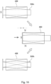
Links
Images







Classifications
-
- B—PERFORMING OPERATIONS; TRANSPORTING
- B62—LAND VEHICLES FOR TRAVELLING OTHERWISE THAN ON RAILS
- B62J—CYCLE SADDLES OR SEATS; AUXILIARY DEVICES OR ACCESSORIES SPECIALLY ADAPTED TO CYCLES AND NOT OTHERWISE PROVIDED FOR, e.g. ARTICLE CARRIERS OR CYCLE PROTECTORS
- B62J1/00—Saddles or other seats for cycles; Arrangement thereof; Component parts
- B62J1/08—Frames for saddles; Connections between saddle frames and seat pillars; Seat pillars
-
- F—MECHANICAL ENGINEERING; LIGHTING; HEATING; WEAPONS; BLASTING
- F15—FLUID-PRESSURE ACTUATORS; HYDRAULICS OR PNEUMATICS IN GENERAL
- F15B—SYSTEMS ACTING BY MEANS OF FLUIDS IN GENERAL; FLUID-PRESSURE ACTUATORS, e.g. SERVOMOTORS; DETAILS OF FLUID-PRESSURE SYSTEMS, NOT OTHERWISE PROVIDED FOR
- F15B15/00—Fluid-actuated devices for displacing a member from one position to another; Gearing associated therewith
- F15B15/20—Other details, e.g. assembly with regulating devices
- F15B15/202—Externally-operated valves mounted in or on the actuator
-
- B—PERFORMING OPERATIONS; TRANSPORTING
- B62—LAND VEHICLES FOR TRAVELLING OTHERWISE THAN ON RAILS
- B62J—CYCLE SADDLES OR SEATS; AUXILIARY DEVICES OR ACCESSORIES SPECIALLY ADAPTED TO CYCLES AND NOT OTHERWISE PROVIDED FOR, e.g. ARTICLE CARRIERS OR CYCLE PROTECTORS
- B62J1/00—Saddles or other seats for cycles; Arrangement thereof; Component parts
- B62J1/08—Frames for saddles; Connections between saddle frames and seat pillars; Seat pillars
- B62J2001/085—Seat pillars having mechanisms to vary seat height, independently of the cycle frame
Definitions
- the present disclosure relates to a retractable seat post. More particularly, the present disclosure relates to an electrically controllable and retractable seat post that has higher retracting speed and stroke.
- a seat post that with a height-adjustable rod has been reached in the market.
- the height of this kind of retractable seat post can be manually controlled to adapt to variant road conditions.
- the saddle can be lowered by adjusting the height of the retractable seat post while riding downhill. Therefore, the center of gravity can be lowered so that the handling can be enhanced and the foot can touch the ground to assist to turn around the corner.
- This kind of retractable seat post is suitable for mountain biking or hillwood road biking owing to its capability of overcoming uncertainties of a rough road.
- a kind of retractable seat post is wire-controlled.
- An exposed wire is connected to the handle bar and the retractable seat post under the saddle, and a lever or other linkage mechanism is used to open a hydraulic or a pneumatic valve thereby elongating or contracting the retractable seat post.
- a lever or other linkage mechanism is used to open a hydraulic or a pneumatic valve thereby elongating or contracting the retractable seat post.
- U height adjustable seat posts comprising an electric motor by means of which a switch can be actuated.
- Patent specification US 8308124 B2 discloses a seat post allowing for a height adjustment of a saddle by means of a wire mechanism by which a switch can be actuated.
- the present invention provides an electrically controllable seat post having the features of claim 1. Further embodiments are subject-matter of the dependent claims.
- the electrically controllable seat post includes a retractable rod and a switch actuator.
- the retractable rod includes a switch and a cylinder, wherein the switch is configured to trigger an elongation and a contraction of the cylinder.
- the switch actuator is corresponding to the switch and includes a pushing member, an electromagnetic coil and a controller.
- the pushing member is linearly movable to open or close the switch so as to drive an elongation and a contraction of the retractable rod via elongation and contraction of the cylinder.
- the electromagnetic coil generates a magnetic force by injecting a current therethrough, wherein the pushing member has a pole of a magnetic field formed at an end of the pushing member by injecting the current through the electromagnetic coil or by a magnetic property at the end of the pushing member.
- the pushing member is directly and non-contactly driven by another pole of a magnetic field formed by the electromagnetic coil to be moved linearly.
- the controller controls the switch actuator.
- the electromagnetic coil includes an inner surface, the inner surface includes a spiral groove, the pushing member includes a protruding member corresponding to the spiral groove, and when the pushing member is elongated or contracted, the protruding member slides in the spiral groove to rotate the pushing member synchronously, so that the pushing member is linearly movable and rotatable to open or close the switch.
- the cylinder is a pneumatic cylinder, a hydraulic cylinder or a liquid-gas modularized cylinder, and the switch is located on the cylinder.
- the retractable rod is a pneumatic rod, a hydraulic rod or a liquid-gas modularized rod.
- the switch is a valve and the pushing member is moved to open or close the valve.
- the switch is a button and the pushing member is moved to push the button.
- the retractable rod includes a rod axis, and a moving direction of the pushing member is perpendicular to the rod axis.
- the switch actuator is immediately adjacent to the retractable rod.
- the electromagnetic coil is located in the retractable rod.
- the electromagnetic coil is located at an end of the retractable rod.
- the electrically controllable seat post includes a recovering member, wherein the recovering member is located between the electromagnetic coil and the pushing member for providing a recovering force.
- the pushing member includes at least one protruded limiting lever, an angle limitation mechanism is assembled outside of the limiting lever, the angle limitation mechanism opens at least one curved opening, the limiting lever is position-limitedly swung in the curved opening, and a rotation angle of the pushing member is constrained by the corporation between the limiting lever and the curved opening.
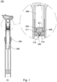
- Fig. 1 is a cross-sectional view of an electrically controllable seat post according to a first embodiment of the present disclosure
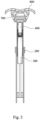
- Fig. 2 is a lateral cross-sectional view of a saddle of the electrically controllable seat post of Fig. 1
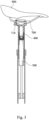
- Fig. 3 is a longitudinal cross-sectional view of the saddle of the electrically controllable seat post of Fig. 2 .
- an electrically controllable seat post 100 includes a retractable rod 200, a cylinder 300, an electromagnetic coil 400, a pushing member 500, a recovering member 600 and a controller 700.
- the electromagnetic coil 400 and the pushing member 500 are operated corporately as a switch actuator (unnumbered).
- the cylinder 300 is fixedly covered in the retractable rod 200.
- the cylinder 300 includes a switch 310 and a rod axis X1.
- a saddle 800 is assembled on the retractable rod 200.
- the switch 310 is used to trigger the elongation and contraction of the cylinder 300, and the elongation and contraction of the cylinder 300 drives the elongation and contraction of the retractable rod 200, thereby raising or lowering the saddle 800 instantly.
- the cylinder 300 can be a pneumatic cylinder, a hydraulic cylinder or a liquid-gas modularized cylinder; similarly, the retractable rod 200 can be a pneumatic rod, a hydraulic rod or a liquid-gas modularized rod. In the embodiment, the cylinder 300 is located inside of the retractable rod 200.
- the electromagnetic coil 400 is assembled in the retractable rod 200 and is corresponding to the switch 310.
- a portion of the pushing member 500 is assembled in the electromagnetic coil 400.
- a central axis X2 of the pushing member 500 is parallel to the rod axis X1 of the cylinder 300.
- One end 510 of the pushing member 500 is linearly moved by the electromagnetic coil 400 to open or close the switch 310.
- the recovering member 600 is made from an elastic material.
- the recovering member 600 provides a recovering force to the end 510 of the pushing member 500 so that the pushing member 500 is recovered to its original position.
- the controller 700 is assembled under the saddle 800.
- the controller 700 controls the electromagnetic coil 400 through a connecting wire 710.
- the central axis X2 of the pushing member 500 is parallel to the rod axis X1; therefore the switch 310 is triggered by the pushing member 500, which is linear activated by the electromagnetic coil 400.
- the controller 700 can control the electromagnetic coil 400 to trigger the switch 310 instantly.
- the recovering member 600 is used to provide the recovering force to the end 510 of the pushing member 500 to recover the pushing member 500 to its original position.
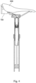
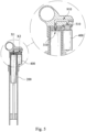
- Fig. 5 is a cross-sectional view of a saddle of an electrically controllable seat post according to a third embodiment of the present disclosure
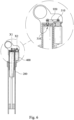
- Fig. 6 is a cross-sectional view of a saddle of an electrically controllable seat post according to a fourth embodiment of the present disclosure.
- the end 510 is indirectly driven to trigger the switch 310, and the electromagnetic coil 400 is located outside of the retractable rod 200 and is assembled immediately adjacent to the retractable rod 200 to ensure that the central axis X2 is parallel to the rod axis X1.
- an inverted-U shaped hydraulic linkage mechanism 910 is located between the end 510 and the switch 310 for triggering the switch 310.
- the hydraulic linkage mechanism 910 includes components such as oil route, piston and oil injection channel, etc., and there is no description herein.
- a swing linkage mechanism 920 is located between the end 510 and the switch 310 for triggering the switch 310.
- the swing linkage mechanism 920 includes components such as a swing lever and a triggering lever, etc., and there is on description herein.
- Fig. 7 is a cross-sectional view of a saddle of an electrically controllable seat post according to a fifth embodiment of the present disclosure
- Fig. 8 is a cross-sectional view of a saddle of an electrically controllable seat post according to a sixth embodiment of the present disclosure.
- the central axis X2 and the rod axis X1 are coaxial, the end 510 is indirectly driven to trigger the switch 310, and the electromagnetic coil 400 is located inside of the retractable rod 200.
- the electromagnetic coil 400 is assembled at an upper end of the retractable rod 200 coaxially (upper end of the cylinder 300).
- an L-shaped linkage mechanism 930 is used to trigger the switch 310.
- the linkage mechanism 930 includes components such as an L-shaped lever and a vertical triggering lever, etc., and there is on description herein.
- the end 510 and the switch 310 are not necessarily located in the same axis owing to the L-shaped linkage mechanism 930.
- a close-type linkage mechanism 940 is located between the end 510 and the switch 310 for triggering the switch 310.
- the linkage mechanism 940 includes components such as double-inclined lever and a triggering lever, etc., and there is on description herein.
- Fig. 9 is a cross-sectional view of a saddle of an electrically controllable seat post according to a seventh embodiment of the present disclosure.
- the central axis X2 and the rod axis X1 are coaxial, the end 510 is indirectly driven to trigger the switch 310, and the electromagnetic coil 400 is located inside of the retractable rod 200.
- the electromagnetic coil 400 is assembled at an upper end of the cylinder 300.
- a vertical-type hydraulic linkage mechanism 950 is located between the end 510 and the switch 310 to trigger the switch 310.
- the vertical-type hydraulic linkage mechanism 950 includes components such as a vertical oil route and a piston, etc., and there is on description herein.
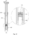
- Fig. 10 is a cross-sectional view of a saddle of an electrically controllable seat post according to an eighth embodiment of the present disclosure
- Fig. 11 is a longitudinal cross-sectional view of the saddle of the electrically controllable seat post of Fig. 10 .
- the central axis X2 and the rod axis X1 are coaxial, the end 510 is indirectly driven to trigger the switch 310, and the electromagnetic coil 400 is located inside of the retractable rod 200.
- the electromagnetic coil 400 is assembled at a bottom end of the cylinder 300.
- the controller 700 (and/or an electric controlling unit such as a battery and a chip, etc.) assembled in the retractable rod 200 can also be used to reduce the amount of components located under the saddle 800.
- Fig. 12 is a cross-sectional view of a saddle of an electrically controllable seat post according to a ninth embodiment of the present disclosure.
- the controller 700 (and/or an electric controlling unit such as a battery and a chip, etc.) is assembled outside of the retractable rod 200.
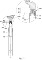
- Fig. 13 is a cross-sectional view of an electrically controllable seat post according to a tenth embodiment of the present disclosure.
- the electrically controllable seat post also includes the retractable rod 200, the electromagnetic coil 400 and the cylinder 300.
- the central axis X2 and the rod axis X1 are vertically arranged, and an L-shaped hydraulic linkage mechanism 960 is corporate with the switch 310 to raise or lower the saddle.
- the linkage mechanism 960 includes components such as double oil routes and piston, etc., and there is no description herein.
- the recovering member 600 is located outside of the electromagnetic coil 400 to provide a recovering force.
- Fig. 14 is a schematic view showing that a pushing member is rotated to open a switch 310 according to an eleventh embodiment of the present disclosure
- Fig. 15 is a schematic view showing that the pushing member is rotated to open the switch 310 of Fig. 14 .
- the pushing member 500 can be linearly moved as in the aforementioned embodiments; or a pushing member 500a can be rotated as in the eleventh embodiment of Fig. 14 .
- the rotation of the pushing member 500a is formed by the corporation of a spiral groove 401a formed in an inner surface of the electromagnetic coil 400a with a protruding member 501a (a steel ball).
- a protruding member 501a a steel ball.
- Fig. 16 shows an operation procedure of an electromagnetic coil and two pushing members
- Fig. 17 shows another operation procedure of the electromagnetic coil and the two pushing members of Fig. 16 .
- the pushing member can have a magnetic property.
- a pushing member 500c having a magnetic property at its end (functioned as an S pole in a magnetic field) and a pushing member 500b having no magnetic property are shown.
- the electromagnetic coil 400 and the pushing member 500b both have no magnetic field before injecting a current.
- the pushing member 500b or the pushing member 500c is linearly moved owing to the repulsion of the magnetic field.
- Fig. 18 a schematic view of an angle limitation mechanism of a pushing member according to a twelfth embodiment of the present disclosure.
- an angle limitation mechanism 970 is assembled in the pushing member 500a.
- the pushing member 500a further includes two L-shaped limiting levers 502a.
- the two limiting levers 502a are assembled diagonally, and a front end of each of the limiting levers 502a is protruded.
- the angle limitation mechanism 970 can be assembled at one end of the electromagnetic coil 400.
- the angle limitation mechanism 970 opens two curved openings 971, the front end of each of the limiting levers 502a is position-limitedly swung in the curved openings 971, and a rotation angle ⁇ of the pushing member 500a is constrained, thereby precisely controlling a movement of the pushing member 500a within the range of the rotation angle ⁇ .
- the present disclosure provides an electrically controllable seat post that using the switch actuator to activate a elongation and contraction of the retractable rod, and has advantages on wireless and precision control, rapid operation and minimizing cable routing.
Landscapes
- Engineering & Computer Science (AREA)
- Mechanical Engineering (AREA)
- Physics & Mathematics (AREA)
- Fluid Mechanics (AREA)
- General Engineering & Computer Science (AREA)
- Seats For Vehicles (AREA)
- Actuator (AREA)
- Lock And Its Accessories (AREA)
- Fluid-Damping Devices (AREA)
Claims (11)
- Montant de selle réglable électriquement (100), comprenant :une tige rétractable (200) comprenant un commutateur (310) et un cylindre (300), dans lequel le commutateur (310) est configuré pour déclencher un allongement et une contraction du cylindre (300) ; etun actionneur de commutateur correspondant au commutateur (310) et comprenant :un élément poussoir (500) qui est linéairement mobile pour ouvrir et fermer le commutateur (310) de manière à entraîner un allongement et une contraction de la tige rétractable (200) par le biais d'un allongement et d'une contraction du cylindre (300) ; etune bobine électromagnétique (400) générant une force magnétique en y injectant un courant ; etun dispositif de commande (700) commandant l'actionneur de commutateur ;dans lequel l'élément poussoir (500) présente un pôle d'un champ magnétique formé à une extrémité de l'élément poussoir (500) en injectant le courant à travers la bobine électromagnétique (400) ou par une propriété magnétique à l'extrémité de l'élément poussoir (500) ;dans lequel l'élément poussoir (500) est entraîné directement et sans contact par un autre pôle d'un champ magnétique formé par la bobine électromagnétique (400) pour être déplacé linéairement ;caractérisé en ce quela bobine électromagnétique (400) comprend une surface intérieure, la surface intérieure comprend une rainure en spirale (401a), l'élément poussoir (500) comprend un élément saillant (501a) correspondant à la rainure en spirale (401a), et lorsque l'élément poussoir (500) est allongé ou contracté, l'élément saillant (501a) glisse dans la rainure en spirale (401a) pour faire pivoter l'élément poussoir (500) de manière synchrone, de sorte que l'élément poussoir (500) soit mobile linéairement et rotatif pour ouvrir et fermer le commutateur (310).
- Montant de selle (100) selon la revendication 1, dans lequel le cylindre (300) est un cylindre pneumatique, un cylindre hydraulique ou un cylindre modulaire liquide-gaz, et le commutateur (310) est situé sur le cylindre (300).
- Montant de selle (100) selon la revendication 1, dans lequel la tige rétractable (200) est une tige pneumatique, une tige hydraulique ou une tige modulaire liquide-gaz.
- Montant de selle selon la revendication 1, dans lequel le commutateur (310) est une soupape et l'élément poussoir (500) est déplacé pour ouvrir et fermer la soupape.
- Montant de selle (100) selon la revendication 1, dans lequel le commutateur (310) est un bouton et l'élément poussoir (500) est déplacé pour appuyer sur le bouton
- Montant de selle (100) selon la revendication 1, dans lequel la tige rétractable (200) présente un axe de tige (X1), et une direction de déplacement de l'élément poussoir (500) est perpendiculaire à l'axe de tige (X1).
- Montant de selle (100) selon la revendication 1, dans lequel l'actionneur de commutateur est immédiatement adjacent à la tige rétractable (200).
- Montant de selle (100) selon la revendication 1, dans lequel la bobine électromagnétique (400a) est située dans la tige rétractable (200).
- Montant de selle (100) selon la revendication 1, dans lequel la bobine électromagnétique (400) est située à une extrémité de la tige rétractable (200).
- Montant de selle (100) selon la revendication 1, comprenant en outre un élément de récupération (600), dans lequel l'élément de récupération (600) est situé entre la bobine électromagnétique (400) et l'élément poussoir (500) pour fournir une force de récupération.
- Montant de selle (100) selon la revendication 1, dans lequel l'élément poussoir (500a) comprend au moins un levier de limitation saillant (502a), un mécanisme de limitation d'angle (970) est assemblé à l'extérieur du levier de limitation (502a), le mécanisme de limitation d'angle (970) ouvre au moins une ouverture incurvée (971), le levier de limitation (502a) est basculé de manière limitée par rapport à la position dans l'ouverture incurvée (971), et un angle de rotation (θ) de l'élément poussoir (500a) est restreint par l'incorporation entre le levier de limitation (502a) et l'ouverture incurvée (971).
Applications Claiming Priority (1)
| Application Number | Priority Date | Filing Date | Title |
|---|---|---|---|
| TW105204620U TWM525882U (zh) | 2016-04-01 | 2016-04-01 | 電控伸縮座桿結構 |
Publications (4)
| Publication Number | Publication Date |
|---|---|
| EP3225519A2 EP3225519A2 (fr) | 2017-10-04 |
| EP3225519A3 EP3225519A3 (fr) | 2017-11-08 |
| EP3225519C0 EP3225519C0 (fr) | 2024-11-06 |
| EP3225519B1 true EP3225519B1 (fr) | 2024-11-06 |
Family
ID=56996614
Family Applications (1)
| Application Number | Title | Priority Date | Filing Date |
|---|---|---|---|
| EP17164431.3A Active EP3225519B1 (fr) | 2016-04-01 | 2017-03-31 | Montant de siège réglable électriquement |
Country Status (5)
| Country | Link |
|---|---|
| US (1) | US20170282986A1 (fr) |
| EP (1) | EP3225519B1 (fr) |
| AU (2) | AU2017202078A1 (fr) |
| CA (1) | CA2962848C (fr) |
| TW (1) | TWM525882U (fr) |
Families Citing this family (8)
| Publication number | Priority date | Publication date | Assignee | Title |
|---|---|---|---|---|
| US10759483B2 (en) | 2015-10-01 | 2020-09-01 | Shimano Inc. | Bicycle and electrical seatpost assembly |
| TWI589475B (zh) | 2016-08-31 | 2017-07-01 | 巨大機械工業股份有限公司 | 可調式自行車座管結構及其自行車 |
| US10843757B2 (en) * | 2017-03-08 | 2020-11-24 | Shimano Inc. | Bicycle electric telescopic apparatus, bicycle power supply system, and bicycle electric component system |
| US10363980B2 (en) * | 2017-06-20 | 2019-07-30 | Tien Hsin Industries Co., Ltd. | Bicycle controlling device |
| US11180212B2 (en) * | 2018-07-17 | 2021-11-23 | Shimano Inc. | Fluid flow control structure for a telescopic apparatus of a human powered vehicle |
| US11697467B2 (en) * | 2020-10-02 | 2023-07-11 | Shimano Inc. | Rider-posture changing device |
| US12291297B2 (en) * | 2022-11-21 | 2025-05-06 | Sram, Llc | Height adjustable seat posts for bicycles |
| US12269547B2 (en) | 2022-11-21 | 2025-04-08 | Sram, Llc | Seat post assembly with automatic power connector |
Family Cites Families (6)
| Publication number | Priority date | Publication date | Assignee | Title |
|---|---|---|---|---|
| JPH02113506A (ja) * | 1988-10-22 | 1990-04-25 | Matsushita Electric Works Ltd | ソレノイド |
| DE4311625A1 (de) * | 1993-04-08 | 1994-10-13 | Stabilus Gmbh | Pneumatische, hydraulische oder hydropneumatische Verstelleinrichtung |
| DE102008047745B4 (de) * | 2008-09-17 | 2015-04-30 | Stabilus Gmbh | Höhenverstellbares Möbelstück |
| US8308124B2 (en) * | 2010-10-28 | 2012-11-13 | Jung Yu Hsu | Control device for adjustable bicycle seat |
| CN203601454U (zh) * | 2013-10-28 | 2014-05-21 | 久鼎金属实业股份有限公司 | 自行车的可调式座管总成 |
| CN204587107U (zh) * | 2015-02-15 | 2015-08-26 | 久鼎金属实业股份有限公司 | 自行车的电子式内外管调整机构 |
-
2016
- 2016-04-01 TW TW105204620U patent/TWM525882U/zh unknown
-
2017
- 2017-03-29 US US15/472,305 patent/US20170282986A1/en not_active Abandoned
- 2017-03-29 AU AU2017202078A patent/AU2017202078A1/en not_active Abandoned
- 2017-03-29 CA CA2962848A patent/CA2962848C/fr active Active
- 2017-03-31 EP EP17164431.3A patent/EP3225519B1/fr active Active
-
2019
- 2019-04-17 AU AU2019202699A patent/AU2019202699B2/en active Active
Also Published As
| Publication number | Publication date |
|---|---|
| EP3225519A2 (fr) | 2017-10-04 |
| TWM525882U (zh) | 2016-07-21 |
| EP3225519C0 (fr) | 2024-11-06 |
| AU2017202078A1 (en) | 2017-10-19 |
| CA2962848A1 (fr) | 2017-10-01 |
| EP3225519A3 (fr) | 2017-11-08 |
| AU2019202699A1 (en) | 2019-05-16 |
| CA2962848C (fr) | 2021-12-07 |
| AU2019202699B2 (en) | 2021-02-04 |
| US20170282986A1 (en) | 2017-10-05 |
Similar Documents
| Publication | Publication Date | Title |
|---|---|---|
| EP3225519B1 (fr) | Montant de siège réglable électriquement | |
| EP2886428B1 (fr) | Ensemble de tube de selle pour bicyclette | |
| JP6590468B2 (ja) | 改良された精密制御により制御される自転車用のギアシフト装置 | |
| TWI770339B (zh) | 自行車伸縮式設備 | |
| CN103189271B (zh) | 雪地机动车悬架负载调节机构 | |
| EP3428048B1 (fr) | Système de direction et d'inclinaison pour un véhicule | |
| EP2402239A1 (fr) | Tige de selle réglable | |
| EP2859920B1 (fr) | Équipement d'exercice | |
| EP2977171A1 (fr) | Machine de soufflage de bouteille | |
| CA2345560A1 (fr) | Foreuse rotative orientable | |
| CN215285077U (zh) | 自行车座杆结构 | |
| JP5806947B2 (ja) | バンドソー装置 | |
| CN115094803B (zh) | 一种市政道路防护栏 | |
| US20190106171A1 (en) | Telescopic seat post | |
| CN106494491B (zh) | 汽车方向盘大行程气动转向管柱 | |
| CN204083333U (zh) | 一种活动式双半球阀 | |
| CN202491039U (zh) | 叉车门架支座组焊定位装置 | |
| JP5525372B2 (ja) | 溶接ガン | |
| CN101391374B (zh) | 一种液压机滑块行程限位装置 | |
| CN105788918B (zh) | 一种绝缘拉杆的装配装置 | |
| CN106245707B (zh) | 行走控制脚踏板总成 | |
| US11767207B2 (en) | Multi-dimensional adjustable forklift driving system | |
| JP2013092015A (ja) | 杭打ち機 | |
| CN203666322U (zh) | 一种能适应各种路面条件的行走装置 | |
| CN221439265U (zh) | 一种用于节流调速的机械装置 |
Legal Events
| Date | Code | Title | Description |
|---|---|---|---|
| PUAI | Public reference made under article 153(3) epc to a published international application that has entered the european phase |
Free format text: ORIGINAL CODE: 0009012 |
|
| STAA | Information on the status of an ep patent application or granted ep patent |
Free format text: STATUS: THE APPLICATION HAS BEEN PUBLISHED |
|
| AK | Designated contracting states |
Kind code of ref document: A2 Designated state(s): AL AT BE BG CH CY CZ DE DK EE ES FI FR GB GR HR HU IE IS IT LI LT LU LV MC MK MT NL NO PL PT RO RS SE SI SK SM TR |
|
| AX | Request for extension of the european patent |
Extension state: BA ME |
|
| PUAL | Search report despatched |
Free format text: ORIGINAL CODE: 0009013 |
|
| AK | Designated contracting states |
Kind code of ref document: A3 Designated state(s): AL AT BE BG CH CY CZ DE DK EE ES FI FR GB GR HR HU IE IS IT LI LT LU LV MC MK MT NL NO PL PT RO RS SE SI SK SM TR |
|
| AX | Request for extension of the european patent |
Extension state: BA ME |
|
| RIC1 | Information provided on ipc code assigned before grant |
Ipc: B62J 1/08 20060101AFI20171003BHEP |
|
| STAA | Information on the status of an ep patent application or granted ep patent |
Free format text: STATUS: REQUEST FOR EXAMINATION WAS MADE |
|
| 17P | Request for examination filed |
Effective date: 20180504 |
|
| RBV | Designated contracting states (corrected) |
Designated state(s): AL AT BE BG CH CY CZ DE DK EE ES FI FR GB GR HR HU IE IS IT LI LT LU LV MC MK MT NL NO PL PT RO RS SE SI SK SM TR |
|
| STAA | Information on the status of an ep patent application or granted ep patent |
Free format text: STATUS: EXAMINATION IS IN PROGRESS |
|
| 17Q | First examination report despatched |
Effective date: 20191204 |
|
| GRAP | Despatch of communication of intention to grant a patent |
Free format text: ORIGINAL CODE: EPIDOSNIGR1 |
|
| STAA | Information on the status of an ep patent application or granted ep patent |
Free format text: STATUS: GRANT OF PATENT IS INTENDED |
|
| INTG | Intention to grant announced |
Effective date: 20240212 |
|
| GRAS | Grant fee paid |
Free format text: ORIGINAL CODE: EPIDOSNIGR3 |
|
| GRAA | (expected) grant |
Free format text: ORIGINAL CODE: 0009210 |
|
| STAA | Information on the status of an ep patent application or granted ep patent |
Free format text: STATUS: THE PATENT HAS BEEN GRANTED |
|
| AK | Designated contracting states |
Kind code of ref document: B1 Designated state(s): AL AT BE BG CH CY CZ DE DK EE ES FI FR GB GR HR HU IE IS IT LI LT LU LV MC MK MT NL NO PL PT RO RS SE SI SK SM TR |
|
| REG | Reference to a national code |
Ref country code: GB Ref legal event code: FG4D |
|
| REG | Reference to a national code |
Ref country code: CH Ref legal event code: EP |
|
| REG | Reference to a national code |
Ref country code: DE Ref legal event code: R096 Ref document number: 602017085893 Country of ref document: DE |
|
| REG | Reference to a national code |
Ref country code: IE Ref legal event code: FG4D |
|
| U01 | Request for unitary effect filed |
Effective date: 20241127 |
|
| U07 | Unitary effect registered |
Designated state(s): AT BE BG DE DK EE FI FR IT LT LU LV MT NL PT RO SE SI Effective date: 20241204 |
|
| PG25 | Lapsed in a contracting state [announced via postgrant information from national office to epo] |
Ref country code: HR Free format text: LAPSE BECAUSE OF FAILURE TO SUBMIT A TRANSLATION OF THE DESCRIPTION OR TO PAY THE FEE WITHIN THE PRESCRIBED TIME-LIMIT Effective date: 20241106 Ref country code: IS Free format text: LAPSE BECAUSE OF FAILURE TO SUBMIT A TRANSLATION OF THE DESCRIPTION OR TO PAY THE FEE WITHIN THE PRESCRIBED TIME-LIMIT Effective date: 20250306 |
|
| PG25 | Lapsed in a contracting state [announced via postgrant information from national office to epo] |
Ref country code: ES Free format text: LAPSE BECAUSE OF FAILURE TO SUBMIT A TRANSLATION OF THE DESCRIPTION OR TO PAY THE FEE WITHIN THE PRESCRIBED TIME-LIMIT Effective date: 20241106 |
|
| PG25 | Lapsed in a contracting state [announced via postgrant information from national office to epo] |
Ref country code: NO Free format text: LAPSE BECAUSE OF FAILURE TO SUBMIT A TRANSLATION OF THE DESCRIPTION OR TO PAY THE FEE WITHIN THE PRESCRIBED TIME-LIMIT Effective date: 20250206 |
|
| PG25 | Lapsed in a contracting state [announced via postgrant information from national office to epo] |
Ref country code: GR Free format text: LAPSE BECAUSE OF FAILURE TO SUBMIT A TRANSLATION OF THE DESCRIPTION OR TO PAY THE FEE WITHIN THE PRESCRIBED TIME-LIMIT Effective date: 20250207 |
|
| PG25 | Lapsed in a contracting state [announced via postgrant information from national office to epo] |
Ref country code: PL Free format text: LAPSE BECAUSE OF FAILURE TO SUBMIT A TRANSLATION OF THE DESCRIPTION OR TO PAY THE FEE WITHIN THE PRESCRIBED TIME-LIMIT Effective date: 20241106 |
|
| PG25 | Lapsed in a contracting state [announced via postgrant information from national office to epo] |
Ref country code: RS Free format text: LAPSE BECAUSE OF FAILURE TO SUBMIT A TRANSLATION OF THE DESCRIPTION OR TO PAY THE FEE WITHIN THE PRESCRIBED TIME-LIMIT Effective date: 20250206 |
|
| U20 | Renewal fee for the european patent with unitary effect paid |
Year of fee payment: 9 Effective date: 20250327 |
|
| PG25 | Lapsed in a contracting state [announced via postgrant information from national office to epo] |
Ref country code: SM Free format text: LAPSE BECAUSE OF FAILURE TO SUBMIT A TRANSLATION OF THE DESCRIPTION OR TO PAY THE FEE WITHIN THE PRESCRIBED TIME-LIMIT Effective date: 20241106 |
|
| PG25 | Lapsed in a contracting state [announced via postgrant information from national office to epo] |
Ref country code: SK Free format text: LAPSE BECAUSE OF FAILURE TO SUBMIT A TRANSLATION OF THE DESCRIPTION OR TO PAY THE FEE WITHIN THE PRESCRIBED TIME-LIMIT Effective date: 20241106 |
|
| PG25 | Lapsed in a contracting state [announced via postgrant information from national office to epo] |
Ref country code: CZ Free format text: LAPSE BECAUSE OF FAILURE TO SUBMIT A TRANSLATION OF THE DESCRIPTION OR TO PAY THE FEE WITHIN THE PRESCRIBED TIME-LIMIT Effective date: 20241106 |
|
| PLBE | No opposition filed within time limit |
Free format text: ORIGINAL CODE: 0009261 |
|
| STAA | Information on the status of an ep patent application or granted ep patent |
Free format text: STATUS: NO OPPOSITION FILED WITHIN TIME LIMIT |
|
| PG25 | Lapsed in a contracting state [announced via postgrant information from national office to epo] |
Ref country code: MC Free format text: LAPSE BECAUSE OF FAILURE TO SUBMIT A TRANSLATION OF THE DESCRIPTION OR TO PAY THE FEE WITHIN THE PRESCRIBED TIME-LIMIT Effective date: 20241106 |
|
| 26N | No opposition filed |
Effective date: 20250807 |
|
| REG | Reference to a national code |
Ref country code: CH Ref legal event code: H13 Free format text: ST27 STATUS EVENT CODE: U-0-0-H10-H13 (AS PROVIDED BY THE NATIONAL OFFICE) Effective date: 20251024 |
|
| PG25 | Lapsed in a contracting state [announced via postgrant information from national office to epo] |
Ref country code: CH Free format text: LAPSE BECAUSE OF NON-PAYMENT OF DUE FEES Effective date: 20250331 |
|
| PG25 | Lapsed in a contracting state [announced via postgrant information from national office to epo] |
Ref country code: IE Free format text: LAPSE BECAUSE OF NON-PAYMENT OF DUE FEES Effective date: 20250331 |
|
| PGFP | Annual fee paid to national office [announced via postgrant information from national office to epo] |
Ref country code: GB Payment date: 20260323 Year of fee payment: 10 |
|
| U20 | Renewal fee for the european patent with unitary effect paid |
Year of fee payment: 10 Effective date: 20260324 |