EP3225546B1 - Drohne, insbesondere vom typ nur-flügel-flugzeug, die mit einem multifunktions-superstrukturelement ausgestattet ist - Google Patents
Drohne, insbesondere vom typ nur-flügel-flugzeug, die mit einem multifunktions-superstrukturelement ausgestattet ist Download PDFInfo
- Publication number
- EP3225546B1 EP3225546B1 EP17156220.0A EP17156220A EP3225546B1 EP 3225546 B1 EP3225546 B1 EP 3225546B1 EP 17156220 A EP17156220 A EP 17156220A EP 3225546 B1 EP3225546 B1 EP 3225546B1
- Authority
- EP
- European Patent Office
- Prior art keywords
- drone
- module
- fuselage
- base portion
- tubular part
- Prior art date
- Legal status (The legal status is an assumption and is not a legal conclusion. Google has not performed a legal analysis and makes no representation as to the accuracy of the status listed.)
- Not-in-force
Links
- 230000008878 coupling Effects 0.000 claims description 6
- 238000010168 coupling process Methods 0.000 claims description 6
- 238000005859 coupling reaction Methods 0.000 claims description 6
- 238000004891 communication Methods 0.000 claims description 4
- 238000010494 dissociation reaction Methods 0.000 claims description 4
- 230000005593 dissociations Effects 0.000 claims description 4
- 239000000463 material Substances 0.000 claims description 4
- 238000013519 translation Methods 0.000 claims description 4
- 230000006355 external stress Effects 0.000 claims description 3
- 239000012530 fluid Substances 0.000 claims description 2
- 239000012780 transparent material Substances 0.000 claims description 2
- 230000000694 effects Effects 0.000 description 4
- 239000000523 sample Substances 0.000 description 4
- 230000035939 shock Effects 0.000 description 4
- 238000005259 measurement Methods 0.000 description 3
- 230000009471 action Effects 0.000 description 2
- 238000013461 design Methods 0.000 description 2
- 230000003068 static effect Effects 0.000 description 2
- 230000000007 visual effect Effects 0.000 description 2
- 241000287531 Psittacidae Species 0.000 description 1
- 230000004913 activation Effects 0.000 description 1
- 230000002457 bidirectional effect Effects 0.000 description 1
- 230000008033 biological extinction Effects 0.000 description 1
- 230000005540 biological transmission Effects 0.000 description 1
- 239000003086 colorant Substances 0.000 description 1
- 238000006073 displacement reaction Methods 0.000 description 1
- 230000010354 integration Effects 0.000 description 1
- 230000003993 interaction Effects 0.000 description 1
- 238000002955 isolation Methods 0.000 description 1
- 230000007257 malfunction Effects 0.000 description 1
- 238000013507 mapping Methods 0.000 description 1
- 238000012544 monitoring process Methods 0.000 description 1
- 229920000515 polycarbonate Polymers 0.000 description 1
- 239000004417 polycarbonate Substances 0.000 description 1
- 230000002250 progressing effect Effects 0.000 description 1
- 230000001681 protective effect Effects 0.000 description 1
- 238000009877 rendering Methods 0.000 description 1
- 230000000284 resting effect Effects 0.000 description 1
- 230000001960 triggered effect Effects 0.000 description 1
- 238000012795 verification Methods 0.000 description 1
- 230000002618 waking effect Effects 0.000 description 1
Images

Classifications
-
- B—PERFORMING OPERATIONS; TRANSPORTING
- B64—AIRCRAFT; AVIATION; COSMONAUTICS
- B64D—EQUIPMENT FOR FITTING IN OR TO AIRCRAFT; FLIGHT SUITS; PARACHUTES; ARRANGEMENT OR MOUNTING OF POWER PLANTS OR PROPULSION TRANSMISSIONS IN AIRCRAFT
- B64D43/00—Arrangements or adaptations of instruments
- B64D43/02—Arrangements or adaptations of instruments for indicating aircraft speed or stalling conditions
-
- B—PERFORMING OPERATIONS; TRANSPORTING
- B64—AIRCRAFT; AVIATION; COSMONAUTICS
- B64C—AEROPLANES; HELICOPTERS
- B64C39/00—Aircraft not otherwise provided for
- B64C39/10—All-wing aircraft
-
- B—PERFORMING OPERATIONS; TRANSPORTING
- B64—AIRCRAFT; AVIATION; COSMONAUTICS
- B64C—AEROPLANES; HELICOPTERS
- B64C1/00—Fuselages; Constructional features common to fuselages, wings, stabilising surfaces or the like
- B64C1/0009—Aerodynamic aspects
-
- B—PERFORMING OPERATIONS; TRANSPORTING
- B64—AIRCRAFT; AVIATION; COSMONAUTICS
- B64D—EQUIPMENT FOR FITTING IN OR TO AIRCRAFT; FLIGHT SUITS; PARACHUTES; ARRANGEMENT OR MOUNTING OF POWER PLANTS OR PROPULSION TRANSMISSIONS IN AIRCRAFT
- B64D47/00—Equipment not otherwise provided for
- B64D47/02—Arrangements or adaptations of signal or lighting devices
-
- B—PERFORMING OPERATIONS; TRANSPORTING
- B64—AIRCRAFT; AVIATION; COSMONAUTICS
- B64U—UNMANNED AERIAL VEHICLES [UAV]; EQUIPMENT THEREFOR
- B64U10/00—Type of UAV
- B64U10/25—Fixed-wing aircraft
-
- G—PHYSICS
- G01—MEASURING; TESTING
- G01P—MEASURING LINEAR OR ANGULAR SPEED, ACCELERATION, DECELERATION, OR SHOCK; INDICATING PRESENCE, ABSENCE, OR DIRECTION, OF MOVEMENT
- G01P5/00—Measuring speed of fluids, e.g. of air stream; Measuring speed of bodies relative to fluids, e.g. of ship, of aircraft
- G01P5/14—Measuring speed of fluids, e.g. of air stream; Measuring speed of bodies relative to fluids, e.g. of ship, of aircraft by measuring differences of pressure in the fluid
- G01P5/16—Measuring speed of fluids, e.g. of air stream; Measuring speed of bodies relative to fluids, e.g. of ship, of aircraft by measuring differences of pressure in the fluid using Pitot tubes, e.g. Machmeter
-
- G—PHYSICS
- G02—OPTICS
- G02B—OPTICAL ELEMENTS, SYSTEMS OR APPARATUS
- G02B6/00—Light guides; Structural details of arrangements comprising light guides and other optical elements, e.g. couplings
- G02B6/0001—Light guides; Structural details of arrangements comprising light guides and other optical elements, e.g. couplings specially adapted for lighting devices or systems
- G02B6/0011—Light guides; Structural details of arrangements comprising light guides and other optical elements, e.g. couplings specially adapted for lighting devices or systems the light guides being planar or of plate-like form
- G02B6/0013—Means for improving the coupling-in of light from the light source into the light guide
-
- G—PHYSICS
- G02—OPTICS
- G02B—OPTICAL ELEMENTS, SYSTEMS OR APPARATUS
- G02B6/00—Light guides; Structural details of arrangements comprising light guides and other optical elements, e.g. couplings
- G02B6/0001—Light guides; Structural details of arrangements comprising light guides and other optical elements, e.g. couplings specially adapted for lighting devices or systems
- G02B6/0011—Light guides; Structural details of arrangements comprising light guides and other optical elements, e.g. couplings specially adapted for lighting devices or systems the light guides being planar or of plate-like form
- G02B6/0033—Means for improving the coupling-out of light from the light guide
- G02B6/005—Means for improving the coupling-out of light from the light guide provided by one optical element, or plurality thereof, placed on the light output side of the light guide
-
- G—PHYSICS
- G02—OPTICS
- G02B—OPTICAL ELEMENTS, SYSTEMS OR APPARATUS
- G02B6/00—Light guides; Structural details of arrangements comprising light guides and other optical elements, e.g. couplings
- G02B6/0001—Light guides; Structural details of arrangements comprising light guides and other optical elements, e.g. couplings specially adapted for lighting devices or systems
- G02B6/0011—Light guides; Structural details of arrangements comprising light guides and other optical elements, e.g. couplings specially adapted for lighting devices or systems the light guides being planar or of plate-like form
- G02B6/0066—Light guides; Structural details of arrangements comprising light guides and other optical elements, e.g. couplings specially adapted for lighting devices or systems the light guides being planar or of plate-like form characterised by the light source being coupled to the light guide
-
- B—PERFORMING OPERATIONS; TRANSPORTING
- B64—AIRCRAFT; AVIATION; COSMONAUTICS
- B64U—UNMANNED AERIAL VEHICLES [UAV]; EQUIPMENT THEREFOR
- B64U2101/00—UAVs specially adapted for particular uses or applications
- B64U2101/30—UAVs specially adapted for particular uses or applications for imaging, photography or videography
-
- B—PERFORMING OPERATIONS; TRANSPORTING
- B64—AIRCRAFT; AVIATION; COSMONAUTICS
- B64U—UNMANNED AERIAL VEHICLES [UAV]; EQUIPMENT THEREFOR
- B64U2201/00—UAVs characterised by their flight controls
- B64U2201/20—Remote controls
-
- G—PHYSICS
- G02—OPTICS
- G02B—OPTICAL ELEMENTS, SYSTEMS OR APPARATUS
- G02B6/00—Light guides; Structural details of arrangements comprising light guides and other optical elements, e.g. couplings
- G02B6/0001—Light guides; Structural details of arrangements comprising light guides and other optical elements, e.g. couplings specially adapted for lighting devices or systems
- G02B6/0011—Light guides; Structural details of arrangements comprising light guides and other optical elements, e.g. couplings specially adapted for lighting devices or systems the light guides being planar or of plate-like form
- G02B6/0065—Manufacturing aspects; Material aspects
-
- G—PHYSICS
- G05—CONTROLLING; REGULATING
- G05D—SYSTEMS FOR CONTROLLING OR REGULATING NON-ELECTRIC VARIABLES
- G05D1/00—Control of position, course, altitude or attitude of land, water, air or space vehicles, e.g. using automatic pilots
- G05D1/0011—Control of position, course, altitude or attitude of land, water, air or space vehicles, e.g. using automatic pilots associated with a remote control arrangement
- G05D1/0038—Control of position, course, altitude or attitude of land, water, air or space vehicles, e.g. using automatic pilots associated with a remote control arrangement by providing the operator with simple or augmented images from one or more cameras located onboard the vehicle, e.g. tele-operation
-
- Y—GENERAL TAGGING OF NEW TECHNOLOGICAL DEVELOPMENTS; GENERAL TAGGING OF CROSS-SECTIONAL TECHNOLOGIES SPANNING OVER SEVERAL SECTIONS OF THE IPC; TECHNICAL SUBJECTS COVERED BY FORMER USPC CROSS-REFERENCE ART COLLECTIONS [XRACs] AND DIGESTS
- Y02—TECHNOLOGIES OR APPLICATIONS FOR MITIGATION OR ADAPTATION AGAINST CLIMATE CHANGE
- Y02T—CLIMATE CHANGE MITIGATION TECHNOLOGIES RELATED TO TRANSPORTATION
- Y02T50/00—Aeronautics or air transport
- Y02T50/10—Drag reduction
Definitions
- the invention relates to remote-controlled motorized flying devices, hereinafter generally referred to as "drones”.
- the invention is advantageously applicable to fixed-wing drones, in particular of the "flying wing” type such as, for example, the SenseFly eBee model, Cheseaux-Lausanne, Switzerland, which is a professional terrain mapping drone equipped with a camera vertical, used especially in agronomy for the monitoring of agricultural crops.
- the "flying wing” type such as, for example, the SenseFly eBee model, Cheseaux-Lausanne, Switzerland, which is a professional terrain mapping drone equipped with a camera vertical, used especially in agronomy for the monitoring of agricultural crops.
- the invention can also be applied to other types of drones, for example rotary-wing drones such as quadcopters, a typical example of which is Parrot Bebop SA, Paris, France, which is a drone equipped with two front and vertical cameras.
- rotary-wing drones such as quadcopters, a typical example of which is Parrot Bebop SA, Paris, France, which is a drone equipped with two front and vertical cameras.
- the simplicity of the implementation of the drone is therefore a particularly important feature to take into account when designing a drone and the definition of its ergonomics vis-à-vis the user.
- the aerodynamic factor is another important feature, and it is necessary to reduce as much as possible the drag introduced by the superstructure elements reported without aerodynamic role such as external sensors, control buttons, accessories, etc.
- the object of the present invention is to propose such a drone equipped with a particular superstructure element making it possible to best meet these various requirements, by a thorough integration of various functions, with simplified ergonomics for the user, maximum robustness against shocks and falls, and a minimal impact on the aerodynamic performance of the drone.
- the invention proposes a flying drone comprising, in a manner known per se, described in particular in the aforementioned "eBee SenseFly Extended User Manual", a fuselage and a superstructure element comprising a flattened tubular piece able to be assembled from protruding from the fuselage of the drone.
- This tubular piece comprises: a proximal end comprising mounting means on the drone; a free distal end with a Pitot Probe dynamic pressure front air intake; an internal conduit in fluid communication with the front air intake, this conduit having an orifice formed on the proximal end and adapted to be connected to a pressure sensor mounted in a module configured in the fuselage of the drone; and a light guide in light communication with a luminescent member mounted near or at the proximal end of the tubular member.
- the tubular piece is a piece movable relative to the fuselage between two predetermined positions, the tubular piece having at its proximal end mechanical coupling means to a contactor mounted in the module, the coupling means being able to activate the contactor between two different states corresponding to said two respective positions.
- a drone 10 has been illustrated, for example a fixed-wing drone such as the SenseFly eBee .
- This drone 10 comprises a fuselage 12 provided at the rear with a propulsion propeller 14 and laterally with two wings 16, these wings possibly being integral with the fuselage 12 in a "flying wing" type configuration.
- a front camera 18 makes it possible to obtain an image of the scene towards which the drone is progressing.
- the drone 10 is controlled by a remote remote control device 20 provided with a touch screen displaying the image captured by the camera 18 and various control commands available to the user.
- the remote control device 20 is provided with means of radio link with the drone, for example of the WiFi local area network type (IEEE 802.11) for the bidirectional exchange of data, from the drone 10 to the device 20, in particular for the transmission of the signal. image captured by the camera 18, and from the camera 20 to the drone 10 for sending pilot commands.
- IEEE 802.11 WiFi local area network type
- the drone 10 comprises in the front part a superstructure element 22 projecting radially perpendicularly to the fuselage 12.
- This superstructure element 22 is externally in the form of a flattened tubular piece extending approximately in a median longitudinal plane of the fuselage, presenting the narrowest side facing the direction of progression of the drone so as to introduce the lowest possible drag.
- the Figure 3 illustrates the main electronic module 24 of the drone, extracted from the fuselage in which it is housed and which plays for this module the role of protective envelope.
- the superstructure element 22 extends from the module 24, of which it constitutes an extension.
- the module 24 When the module 24 is enclosed in the fuselage 12, only the upper part of the element 22 projects through an opening 25 of the fuselage ( Figure 2 ), the lower part of the element 22 and the entire module 24 remaining enclosed in the fuselage and protected by it.
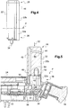
- FIGs 4 and 5 show in more detail the structure of the superstructure element 22, alone ( Figure 4 ) and with the different elements of the front part of the module 24 where this element 22 is mounted ( Figure 5 ).
- the superstructure element 22 comprises a proximal end 26, on the module side, and a free distal end 28, corresponding to the emergent portion projecting above the fuselage of the drone.
- the element 22 is formed of two parts nested in the extension of one another, with a base portion 22a, proximal side, connected to the module 24, and a removable projecting portion 22b, distal side, surmounting the base portion 22a. These two parts 22a and 22b extend on either side of a plane P and are nested together with a functional adjustment allowing their mutual dissociation in case of excessive external stress experienced by the projecting portion 22.
- the portion 22, which projects out of the fuselage may be ejected and replaced if it is damaged, while the base portion 22a, located inside the fuselage, will remain in place with the module 24, which will not be damaged by the shock.
- the base portion 22a is mounted in the module 24 in a guide hole 30 allowing a displacement in vertical translation in a direction perpendicular to the fuselage, for example under the effect of a support (arrow 32) exerted on the distal end 28 by a user (the "vertical" direction being heard with the representation of the Figures 4 and 5 , that is to say in a radial plane with respect to the main axis of the drone and the module 24).
- the base portion 22a is provided at the bottom with a pusher member 34 resting on an articulated lever 36 whose end biases an electric contactor 38 mounted on the printed circuit board 40 of the module 24.
- a support (arrow 32) on the distal end of the superstructure element 22 will thus have the effect of actuating the switch 38, and the release of this support, the return of the switch 38 to its initial rest position.
- Elastic return means (not shown) are provided for biasing the superstructure element 22 upwards in the guide orifice 30 and to allow the actuation of the contactor 40, which is fugitive type, only during the duration of the support on the end of the superstructure element 22.
- the protruding portion 22b includes an inner conduit 42 extending along its length and opening, distal side, by a front air intake 44 and, proximal, by an outlet 46.
- the frontal air intake 44 is oriented towards the direction of progression of the drone. It is located in the part of the superstructure element 22 which emerges from the fuselage, and in a region of the distal end 28 which allows it to be located at a distance from the fuselage surface, as can be seen in particular on the Figure 2 .
- the front air intake 44 is a Pitot Probe dynamic pressure air intake.
- the pressure collected at the plug 44 is transmitted by the internal conduit 42 to the outlet 46 and then, by a flexible connection 48, to a pressure sensor mounted on the printed circuit board 40, where is also mounted another sensor for the measurement of the static pressure, the differential between static pressure and dynamic pressure making it possible to obtain a measurement of the speed of the drone with respect to the air (relative wind).
- a pressure sensor mounted on the printed circuit board 40 where is also mounted another sensor for the measurement of the static pressure, the differential between static pressure and dynamic pressure making it possible to obtain a measurement of the speed of the drone with respect to the air (relative wind).
- the protruding portion 22b of the superstructure member 22 further includes a recess 50 on the side where it is engaged on the base portion 22a.
- This cavity 50 houses the head of a light-emitting diode 52 whose base is mounted and supported by the base portion 22a.
- the material 54 of the projecting part 22b is a transparent or translucent material, for example a polycarbonate, allowing this projecting part 22b to act as a light guide for the superstructure element 22, the activation of the diode 52 to illuminate the projecting portion 22b and in particular its portion that emerges from the fuselage, while the diode 52 remains housed inside the fuselage where it is protected.
- the superstructure element whose arrangement has just been described makes it possible to combine several functions in an advantageous manner, both for the user and for the design of the drone.
- the starting of the drone of the invention is done by pressing (arrow 32) on the free end of the superstructure element 22, which has the effect of actuating the switch 38.
- This maneuver leads to the sending to module 24 processor a signal that will trigger the waking of the circuits, powering the power supply, etc. and verification that all conditions are met for launch in flight.
- the light guide function provides the user with a visual feedback on the state of the drone, by switching on / off the light-emitting diode 52 located inside this fuselage but visible from the outside of the fuselage by the light guide.
- light 54 if necessary using different colors depending on the different states of the drone (off, ready to take off, malfunction, etc.).
- the frontal air intake 44 disposed in the most distal region of the emerging part of the superstructure element 22, at a distance from the fuselage, provides excellent dynamic pressure capture, in a laminar flow that is not not disturbed by the effects of turbulence and boundary layer present on the surface of the fuselage of the drone.
- the superstructure element 22 allows the module 24, which remains enclosed in the mechanical structure of the fuselage and protected by it, to have access to the outside world for three main functions, namely i) switching on / off drone circuits, ii) the provision of visual information to the user on the condition of the drone, and iii) the provision of a Pitot probe dynamic pressure air intake to measure the air speed of the drone when it is moving.
- the superstructure element 22 allows these interactions of the module 24 with the outside world without the user having to manipulate the electronic module, which remains carefully confined and protected in the mechanical structure of the drone, while rendering accessible these three functions from outside the drone, and this by one and the same apparent part outside the drone.
- the separable nature of the protruding portion 22b from the base portion 22a mounted on the module 24 ensures that, even in the event of a violent impact, the most fragile elements remain protected.
- These elements are: the light-emitting diode 52, the link 48 between the internal duct communicating with the front air intake 44 and the pressure sensor mounted on the printed circuit board 40, the mobile support and guiding system of the part base 22a in the orifice 30, as well as the operating system of the contactor 38.
- These elements are all connected directly or indirectly to the base portion 22a but not to the removable projecting portion 22b, and they all remain elsewhere all located at inside the fuselage 12 where they are protected. In the event of an impact, only the protruding part 22b, which is only an easily replaceable one-piece molded part having no added element, will be ejected or broken.
Landscapes
- Engineering & Computer Science (AREA)
- Aviation & Aerospace Engineering (AREA)
- Physics & Mathematics (AREA)
- Mechanical Engineering (AREA)
- General Physics & Mathematics (AREA)
- Optics & Photonics (AREA)
- Fluid Mechanics (AREA)
- Remote Sensing (AREA)
- Toys (AREA)
Claims (9)
- Fliegende Drohne (10), umfassend einen Rumpf (12) und ein Aufbauelement, das ein abgeflachtes röhrenförmiges Teil (22) umfasst, das von dem Rumpf der Drohne vorspringend montiert ist, wobei das röhrenförmige Teil (22) Folgendes umfasst:- ein proximales Ende (26), das Mittel zur Montage an der Drohne umfasst;- ein freies distales Ende (28) mit einer frontalen Staudruck-Lufthutze für eine Staudrucksonde (44)- eine innenliegende Rohrleitung (42) in Strömungsverbindung mit der frontalen Lufthutze (44), wobei diese Rohrleitung eine Öffnung (46) hat, die an dem proximalen Ende gebildet ist und mit einem Drucksensor verbunden ist, der in einem Modul (24) montiert ist, das in dem Rumpf (12) der Drohne ausgestaltet ist; und- einen Lichtleiter (54) in Lichtverbindung mit einem Lumineszenzorgan (52), das in der Nähe oder im Bereich des proximalen Endes (26) des röhrenförmigen Teils (22) montiert ist,dadurch gekennzeichnet, dass das röhrenförmige Teil (22) ein Teil ist, das relativ zu dem Rumpf (12) zwischen zwei vorbestimmten Positionen beweglich ist, wobei das röhrenförmige Teil (22) an seinem proximalen Ende Mittel (34) für die mechanische Ankopplung an ein Schütz (38) aufweist, das in dem Modul (24) montiert ist, wobei die Ankopplungsmittel (34) in der Lage sind, das Schütz (38) zwischen zwei unterschiedlichen Zuständen zu aktivieren, die den zwei jeweiligen Positionen entsprechen.
- Drohne nach Anspruch 1, wobei das röhrenförmige Teil (22) ein Teil ist, das in vertikaler Translation (32) zwischen zwei vorbestimmten Positionen entlang einer Normalenrichtung zu dem Rumpf (12) in der Region des proximalen Endes (26) beweglich ist.
- Drohne nach Anspruch 1, wobei das röhrenförmige Teil (22) zwei Teile (22a, 22b) umfasst, die trennbar in der Verlängerung des einen von dem anderen in Eingriff sind, mit- einem Basisteil (22a), das auf permanente Weise mit dem Modul (24) verbunden ist und die Mittel (34) für die mechanische Ankopplung an das Schütz (38) trägt, und- einem lösbaren vorspringenden Teil (22b), welches das Basisteil (22a) überragt und die frontale Lufthutze (44) und die innenliegende Rohrleitung (42) aufweist.
- Drohne nach Anspruch 3, wobei der Basisteil (22a) und der vorspringende Teil (22b) durch Ineingriffnahme mit einer funktionalen Verbindung zusammenwirken, die deren gegenseitiges Lösen für den Fall übermäßigen äußeren Drucks, dem der vorspringende Teil (22b) ausgesetzt ist, gestatten.
- Drohne nach Anspruch 3, wobei der Basisteil (22a) sich teilweise innerhalb des Moduls (24) und teilweise außerhalb des Moduls (24) erstreckt und der vorspringende Teil (22b) sich vollständig außerhalb des Moduls (24) erstreckt.
- Drohne nach Anspruch 5, wobei der Basisteil (22a) sich vollständig innerhalb des Rumpfes (12) erstreckt.
- Drohne nach Anspruch 3, wobei der Basisteil (22a) eine Halterung für das Lumineszenzorgan (52) umfasst.
- Drohne nach Anspruch 7, wobei der vorspringende Teil (22b) ein Teil aus einem durchscheinenden oder transparenten Material (54) ist, das den Lichtleiter bildet, das von dem Material verschieden ist, das den Basisteil (22a) bildet.
- Drohne nach Anspruch 3, wobei die Öffnung (46) der innenliegenden Rohrleitung (42) von dem röhrenförmigen Teil (22) zu dem inneren Volumen des Moduls (24) hin im Bereich der Verbindung des vorspringenden Teils (22b) mit dem Basisteil (22a) ausmündet.
Applications Claiming Priority (1)
| Application Number | Priority Date | Filing Date | Title |
|---|---|---|---|
| FR1652148A FR3048958A1 (fr) | 2016-03-15 | 2016-03-15 | Element de superstructure pour drone volant, notamment un drone de type aile volante. |
Publications (2)
| Publication Number | Publication Date |
|---|---|
| EP3225546A1 EP3225546A1 (de) | 2017-10-04 |
| EP3225546B1 true EP3225546B1 (de) | 2018-07-11 |
Family
ID=56119530
Family Applications (1)
| Application Number | Title | Priority Date | Filing Date |
|---|---|---|---|
| EP17156220.0A Not-in-force EP3225546B1 (de) | 2016-03-15 | 2017-02-15 | Drohne, insbesondere vom typ nur-flügel-flugzeug, die mit einem multifunktions-superstrukturelement ausgestattet ist |
Country Status (4)
| Country | Link |
|---|---|
| US (1) | US20170267372A1 (de) |
| EP (1) | EP3225546B1 (de) |
| CN (1) | CN107187600A (de) |
| FR (1) | FR3048958A1 (de) |
Families Citing this family (8)
| Publication number | Priority date | Publication date | Assignee | Title |
|---|---|---|---|---|
| WO2018071727A1 (en) | 2016-10-12 | 2018-04-19 | Aker Technologies, Inc. | System for monitoring crops and soil conditions |
| WO2019037100A1 (en) * | 2017-08-25 | 2019-02-28 | SZ DJI Technology Co., Ltd. | ALTITUDE ESTIMATION FOR AERIAL VEHICLES |
| FR3080094B1 (fr) * | 2018-04-16 | 2020-03-20 | Airbus Helicopters | Procede de preparation au decollage d'un drone, drone et systeme de preparation associes |
| US11454572B2 (en) | 2020-06-04 | 2022-09-27 | Saudi Arabian Oil Company | Method of placing gas sensors on drones to benefit from thrust air flow via placement and scoops |
| US11565794B2 (en) | 2020-06-04 | 2023-01-31 | Saudi Arabian Oil Company | Gas sensing for fixed wing drones using scoops |
| US11603214B2 (en) * | 2020-06-04 | 2023-03-14 | Saudi Arabian Oil Company | Calibration methods for gas sensors mounted in-stream of drone propeller air flow |
| US11555825B1 (en) | 2020-11-24 | 2023-01-17 | Sentera, Inc. | Pitot probe assembly with replaceable tip and damping |
| CN113125800B (zh) * | 2021-04-19 | 2023-01-06 | 重庆地格科技有限责任公司 | 基于皮托管的风速风向测量方法 |
Family Cites Families (8)
| Publication number | Priority date | Publication date | Assignee | Title |
|---|---|---|---|---|
| US6847865B2 (en) * | 2001-09-27 | 2005-01-25 | Ernest A. Carroll | Miniature, unmanned aircraft with onboard stabilization and automated ground control of flight path |
| WO2013062608A2 (en) * | 2011-08-19 | 2013-05-02 | Aerovironment Inc. | Inverted-landing aircraft |
| WO2013028221A1 (en) * | 2011-08-19 | 2013-02-28 | Aerovironment Inc. | Deep stall aircraft landing |
| US9011250B2 (en) * | 2012-10-05 | 2015-04-21 | Qfo Labs, Inc. | Wireless communication system for game play with multiple remote-control flying craft |
| US10321663B2 (en) * | 2015-09-24 | 2019-06-18 | Digi-Star, Llc | Agricultural drone for use in livestock monitoring |
| US10017271B2 (en) * | 2016-03-18 | 2018-07-10 | Sunlight Photonics Inc. | Methods of three dimensional (3D) airflow sensing and analysis |
| US10308370B2 (en) * | 2016-06-12 | 2019-06-04 | William L. Hinks | Unusual state alarm and recovery director |
| US10048103B2 (en) * | 2016-09-23 | 2018-08-14 | Bell Helicopter Textron Inc. | Adjustable position pitot probe mount |
-
2016
- 2016-03-15 FR FR1652148A patent/FR3048958A1/fr not_active Withdrawn
-
2017
- 2017-02-15 EP EP17156220.0A patent/EP3225546B1/de not_active Not-in-force
- 2017-03-14 US US15/458,225 patent/US20170267372A1/en not_active Abandoned
- 2017-03-14 CN CN201710151820.4A patent/CN107187600A/zh not_active Withdrawn
Non-Patent Citations (1)
| Title |
|---|
| None * |
Also Published As
| Publication number | Publication date |
|---|---|
| FR3048958A1 (fr) | 2017-09-22 |
| EP3225546A1 (de) | 2017-10-04 |
| CN107187600A (zh) | 2017-09-22 |
| US20170267372A1 (en) | 2017-09-21 |
Similar Documents
| Publication | Publication Date | Title |
|---|---|---|
| EP3225546A1 (de) | Drohne, insbesondere vom typ nur-flügel-flugzeug, die mit einem multifunktions-superstrukturelement ausgestattet ist | |
| EP3210658B1 (de) | Drohne, die mit hochklappbaren drohnenhalterungen ausgestattet ist | |
| CA1229584A (fr) | Dispositif de securite pour l'ouverture d'une porte d'aeronef | |
| EP0718731B1 (de) | Vorrichtung zum Betreiben eines gesteuerten Elementes für ein Flugzeug, insbesondere Hubschrauber, mit elektrischen Flugsteuerungen | |
| EP3210659B1 (de) | Drohne, die mit einem batterieblock mit aussteifungsfunktion ausgestattet ist | |
| EP3210660A1 (de) | Drohne mit zusammenklappbaren verbindungsarmen | |
| EP2038176B1 (de) | Motoranordnung für ein luftfahrzeug mit an zwei getrennten elementen angebrachter aerodynamischer kupplungsverteilung | |
| EP1486418B1 (de) | Triebwerksgondelaufhängung für Luftfahrzeuge | |
| EP3282335A1 (de) | Integriertes kontroll-/steuermodul für flugdrohne | |
| EP1458256A1 (de) | Mundbetätigte steuervorrichtung für ein an einem helm befestigtes beleuchtungssystem | |
| EP3271244B1 (de) | Vorrichtung zur flugsteuerung eines luftfahrzeugs | |
| FR2900634A1 (fr) | Amenagement de poste de pilotage pour aeronef | |
| FR2737392A1 (fr) | Appareil de liberation de la visiere d'un casque | |
| EP3386862B1 (de) | Ram-air-turbine system umfassend eine vorrichtung um die drehung der turbine zu blockieren | |
| FR3058805A1 (fr) | Dispositif de gestion de l'energie mecanique d'un aeronef, presentant un systeme auxiliaire de gestion d'energie, aeronef et procede associes | |
| EP3112260B1 (de) | Verfahren zur steuerung von aerodynamischen mitteln eines luftfahrzeugs, entsprechendes steuerverfahren und mit einem solchen steuerverfahren ausgerüstetes luftfahrzeug | |
| WO2019175264A1 (fr) | Procedure de manœuvre d'un aerodyne hybride de type vtol ou stol | |
| EP1113730B1 (de) | Modularer helm | |
| EP0213036B1 (de) | Vorrichtung zum teilweisen Öffnen der Tür eines eine Sicherheitsausrüstung zum Beispiel Sauerstoffmasken enthaltenden Faches | |
| WO2019243694A1 (fr) | Dispositif et procédé de communication de données dans un sous-ensemble d'aéronef | |
| EP1895865B1 (de) | Vorrichtung zur befestigung eines visiers an einer helmschale | |
| EP0481860A1 (de) | Vorrichtung zum Verriegeln einer Visierscheibe und Helm mit wenigstens einer derartigen Vorrichtung | |
| EP1427632B1 (de) | Fesselballon und zugehörige steuereinrichtung | |
| FR2571021A1 (fr) | Dispositif pour la commande automatique d'un compensateur aerodynamique associe a une surface aerodynamique de commande d'un aeronef | |
| WO2021255053A1 (fr) | Dispositif d'accrochage d'un drone |
Legal Events
| Date | Code | Title | Description |
|---|---|---|---|
| PUAI | Public reference made under article 153(3) epc to a published international application that has entered the european phase |
Free format text: ORIGINAL CODE: 0009012 |
|
| STAA | Information on the status of an ep patent application or granted ep patent |
Free format text: STATUS: THE APPLICATION HAS BEEN PUBLISHED |
|
| AK | Designated contracting states |
Kind code of ref document: A1 Designated state(s): AL AT BE BG CH CY CZ DE DK EE ES FI FR GB GR HR HU IE IS IT LI LT LU LV MC MK MT NL NO PL PT RO RS SE SI SK SM TR |
|
| AX | Request for extension of the european patent |
Extension state: BA ME |
|
| STAA | Information on the status of an ep patent application or granted ep patent |
Free format text: STATUS: REQUEST FOR EXAMINATION WAS MADE |
|
| 17P | Request for examination filed |
Effective date: 20171219 |
|
| RBV | Designated contracting states (corrected) |
Designated state(s): AL AT BE BG CH CY CZ DE DK EE ES FI FR GB GR HR HU IE IS IT LI LT LU LV MC MK MT NL NO PL PT RO RS SE SI SK SM TR |
|
| REG | Reference to a national code |
Ref country code: DE Ref legal event code: R079 Ref document number: 602017000136 Country of ref document: DE Free format text: PREVIOUS MAIN CLASS: B64C0039020000 Ipc: B64D0047020000 |
|
| GRAP | Despatch of communication of intention to grant a patent |
Free format text: ORIGINAL CODE: EPIDOSNIGR1 |
|
| STAA | Information on the status of an ep patent application or granted ep patent |
Free format text: STATUS: GRANT OF PATENT IS INTENDED |
|
| RIC1 | Information provided on ipc code assigned before grant |
Ipc: B64C 39/02 20060101ALI20180124BHEP Ipc: B64C 1/00 20060101ALI20180124BHEP Ipc: B64D 43/02 20060101ALI20180124BHEP Ipc: B64D 47/08 20060101ALN20180124BHEP Ipc: B64D 47/02 20060101AFI20180124BHEP |
|
| INTG | Intention to grant announced |
Effective date: 20180220 |
|
| GRAS | Grant fee paid |
Free format text: ORIGINAL CODE: EPIDOSNIGR3 |
|
| GRAA | (expected) grant |
Free format text: ORIGINAL CODE: 0009210 |
|
| STAA | Information on the status of an ep patent application or granted ep patent |
Free format text: STATUS: THE PATENT HAS BEEN GRANTED |
|
| AK | Designated contracting states |
Kind code of ref document: B1 Designated state(s): AL AT BE BG CH CY CZ DE DK EE ES FI FR GB GR HR HU IE IS IT LI LT LU LV MC MK MT NL NO PL PT RO RS SE SI SK SM TR |
|
| REG | Reference to a national code |
Ref country code: GB Ref legal event code: FG4D Free format text: NOT ENGLISH |
|
| REG | Reference to a national code |
Ref country code: CH Ref legal event code: EP |
|
| REG | Reference to a national code |
Ref country code: AT Ref legal event code: REF Ref document number: 1016630 Country of ref document: AT Kind code of ref document: T Effective date: 20180715 |
|
| REG | Reference to a national code |
Ref country code: IE Ref legal event code: FG4D Free format text: LANGUAGE OF EP DOCUMENT: FRENCH |
|
| REG | Reference to a national code |
Ref country code: DE Ref legal event code: R096 Ref document number: 602017000136 Country of ref document: DE |
|
| REG | Reference to a national code |
Ref country code: NL Ref legal event code: MP Effective date: 20180711 |
|
| REG | Reference to a national code |
Ref country code: LT Ref legal event code: MG4D |
|
| REG | Reference to a national code |
Ref country code: AT Ref legal event code: MK05 Ref document number: 1016630 Country of ref document: AT Kind code of ref document: T Effective date: 20180711 |
|
| PG25 | Lapsed in a contracting state [announced via postgrant information from national office to epo] |
Ref country code: NL Free format text: LAPSE BECAUSE OF FAILURE TO SUBMIT A TRANSLATION OF THE DESCRIPTION OR TO PAY THE FEE WITHIN THE PRESCRIBED TIME-LIMIT Effective date: 20180711 |
|
| PG25 | Lapsed in a contracting state [announced via postgrant information from national office to epo] |
Ref country code: BG Free format text: LAPSE BECAUSE OF FAILURE TO SUBMIT A TRANSLATION OF THE DESCRIPTION OR TO PAY THE FEE WITHIN THE PRESCRIBED TIME-LIMIT Effective date: 20181011 Ref country code: SE Free format text: LAPSE BECAUSE OF FAILURE TO SUBMIT A TRANSLATION OF THE DESCRIPTION OR TO PAY THE FEE WITHIN THE PRESCRIBED TIME-LIMIT Effective date: 20180711 Ref country code: NO Free format text: LAPSE BECAUSE OF FAILURE TO SUBMIT A TRANSLATION OF THE DESCRIPTION OR TO PAY THE FEE WITHIN THE PRESCRIBED TIME-LIMIT Effective date: 20181011 Ref country code: AT Free format text: LAPSE BECAUSE OF FAILURE TO SUBMIT A TRANSLATION OF THE DESCRIPTION OR TO PAY THE FEE WITHIN THE PRESCRIBED TIME-LIMIT Effective date: 20180711 Ref country code: PL Free format text: LAPSE BECAUSE OF FAILURE TO SUBMIT A TRANSLATION OF THE DESCRIPTION OR TO PAY THE FEE WITHIN THE PRESCRIBED TIME-LIMIT Effective date: 20180711 Ref country code: IS Free format text: LAPSE BECAUSE OF FAILURE TO SUBMIT A TRANSLATION OF THE DESCRIPTION OR TO PAY THE FEE WITHIN THE PRESCRIBED TIME-LIMIT Effective date: 20181111 Ref country code: FI Free format text: LAPSE BECAUSE OF FAILURE TO SUBMIT A TRANSLATION OF THE DESCRIPTION OR TO PAY THE FEE WITHIN THE PRESCRIBED TIME-LIMIT Effective date: 20180711 Ref country code: GR Free format text: LAPSE BECAUSE OF FAILURE TO SUBMIT A TRANSLATION OF THE DESCRIPTION OR TO PAY THE FEE WITHIN THE PRESCRIBED TIME-LIMIT Effective date: 20181012 Ref country code: LT Free format text: LAPSE BECAUSE OF FAILURE TO SUBMIT A TRANSLATION OF THE DESCRIPTION OR TO PAY THE FEE WITHIN THE PRESCRIBED TIME-LIMIT Effective date: 20180711 Ref country code: RS Free format text: LAPSE BECAUSE OF FAILURE TO SUBMIT A TRANSLATION OF THE DESCRIPTION OR TO PAY THE FEE WITHIN THE PRESCRIBED TIME-LIMIT Effective date: 20180711 |
|
| PG25 | Lapsed in a contracting state [announced via postgrant information from national office to epo] |
Ref country code: HR Free format text: LAPSE BECAUSE OF FAILURE TO SUBMIT A TRANSLATION OF THE DESCRIPTION OR TO PAY THE FEE WITHIN THE PRESCRIBED TIME-LIMIT Effective date: 20180711 Ref country code: LV Free format text: LAPSE BECAUSE OF FAILURE TO SUBMIT A TRANSLATION OF THE DESCRIPTION OR TO PAY THE FEE WITHIN THE PRESCRIBED TIME-LIMIT Effective date: 20180711 Ref country code: AL Free format text: LAPSE BECAUSE OF FAILURE TO SUBMIT A TRANSLATION OF THE DESCRIPTION OR TO PAY THE FEE WITHIN THE PRESCRIBED TIME-LIMIT Effective date: 20180711 |
|
| REG | Reference to a national code |
Ref country code: DE Ref legal event code: R097 Ref document number: 602017000136 Country of ref document: DE |
|
| PG25 | Lapsed in a contracting state [announced via postgrant information from national office to epo] |
Ref country code: ES Free format text: LAPSE BECAUSE OF FAILURE TO SUBMIT A TRANSLATION OF THE DESCRIPTION OR TO PAY THE FEE WITHIN THE PRESCRIBED TIME-LIMIT Effective date: 20180711 Ref country code: EE Free format text: LAPSE BECAUSE OF FAILURE TO SUBMIT A TRANSLATION OF THE DESCRIPTION OR TO PAY THE FEE WITHIN THE PRESCRIBED TIME-LIMIT Effective date: 20180711 Ref country code: IT Free format text: LAPSE BECAUSE OF FAILURE TO SUBMIT A TRANSLATION OF THE DESCRIPTION OR TO PAY THE FEE WITHIN THE PRESCRIBED TIME-LIMIT Effective date: 20180711 Ref country code: RO Free format text: LAPSE BECAUSE OF FAILURE TO SUBMIT A TRANSLATION OF THE DESCRIPTION OR TO PAY THE FEE WITHIN THE PRESCRIBED TIME-LIMIT Effective date: 20180711 Ref country code: CZ Free format text: LAPSE BECAUSE OF FAILURE TO SUBMIT A TRANSLATION OF THE DESCRIPTION OR TO PAY THE FEE WITHIN THE PRESCRIBED TIME-LIMIT Effective date: 20180711 |
|
| PGFP | Annual fee paid to national office [announced via postgrant information from national office to epo] |
Ref country code: DE Payment date: 20190219 Year of fee payment: 3 |
|
| PLBE | No opposition filed within time limit |
Free format text: ORIGINAL CODE: 0009261 |
|
| STAA | Information on the status of an ep patent application or granted ep patent |
Free format text: STATUS: NO OPPOSITION FILED WITHIN TIME LIMIT |
|
| PG25 | Lapsed in a contracting state [announced via postgrant information from national office to epo] |
Ref country code: SK Free format text: LAPSE BECAUSE OF FAILURE TO SUBMIT A TRANSLATION OF THE DESCRIPTION OR TO PAY THE FEE WITHIN THE PRESCRIBED TIME-LIMIT Effective date: 20180711 Ref country code: SM Free format text: LAPSE BECAUSE OF FAILURE TO SUBMIT A TRANSLATION OF THE DESCRIPTION OR TO PAY THE FEE WITHIN THE PRESCRIBED TIME-LIMIT Effective date: 20180711 Ref country code: DK Free format text: LAPSE BECAUSE OF FAILURE TO SUBMIT A TRANSLATION OF THE DESCRIPTION OR TO PAY THE FEE WITHIN THE PRESCRIBED TIME-LIMIT Effective date: 20180711 |
|
| PGFP | Annual fee paid to national office [announced via postgrant information from national office to epo] |
Ref country code: FR Payment date: 20190213 Year of fee payment: 3 |
|
| 26N | No opposition filed |
Effective date: 20190412 |
|
| PG25 | Lapsed in a contracting state [announced via postgrant information from national office to epo] |
Ref country code: SI Free format text: LAPSE BECAUSE OF FAILURE TO SUBMIT A TRANSLATION OF THE DESCRIPTION OR TO PAY THE FEE WITHIN THE PRESCRIBED TIME-LIMIT Effective date: 20180711 |
|
| PG25 | Lapsed in a contracting state [announced via postgrant information from national office to epo] |
Ref country code: LU Free format text: LAPSE BECAUSE OF NON-PAYMENT OF DUE FEES Effective date: 20190215 Ref country code: MC Free format text: LAPSE BECAUSE OF FAILURE TO SUBMIT A TRANSLATION OF THE DESCRIPTION OR TO PAY THE FEE WITHIN THE PRESCRIBED TIME-LIMIT Effective date: 20180711 |
|
| REG | Reference to a national code |
Ref country code: BE Ref legal event code: MM Effective date: 20190228 |
|
| REG | Reference to a national code |
Ref country code: IE Ref legal event code: MM4A |
|
| PG25 | Lapsed in a contracting state [announced via postgrant information from national office to epo] |
Ref country code: IE Free format text: LAPSE BECAUSE OF NON-PAYMENT OF DUE FEES Effective date: 20190215 |
|
| PG25 | Lapsed in a contracting state [announced via postgrant information from national office to epo] |
Ref country code: BE Free format text: LAPSE BECAUSE OF NON-PAYMENT OF DUE FEES Effective date: 20190228 |
|
| PG25 | Lapsed in a contracting state [announced via postgrant information from national office to epo] |
Ref country code: TR Free format text: LAPSE BECAUSE OF FAILURE TO SUBMIT A TRANSLATION OF THE DESCRIPTION OR TO PAY THE FEE WITHIN THE PRESCRIBED TIME-LIMIT Effective date: 20180711 |
|
| PG25 | Lapsed in a contracting state [announced via postgrant information from national office to epo] |
Ref country code: MT Free format text: LAPSE BECAUSE OF FAILURE TO SUBMIT A TRANSLATION OF THE DESCRIPTION OR TO PAY THE FEE WITHIN THE PRESCRIBED TIME-LIMIT Effective date: 20180711 Ref country code: PT Free format text: LAPSE BECAUSE OF FAILURE TO SUBMIT A TRANSLATION OF THE DESCRIPTION OR TO PAY THE FEE WITHIN THE PRESCRIBED TIME-LIMIT Effective date: 20181111 |
|
| REG | Reference to a national code |
Ref country code: DE Ref legal event code: R119 Ref document number: 602017000136 Country of ref document: DE |
|
| REG | Reference to a national code |
Ref country code: CH Ref legal event code: PL |
|
| PG25 | Lapsed in a contracting state [announced via postgrant information from national office to epo] |
Ref country code: CH Free format text: LAPSE BECAUSE OF NON-PAYMENT OF DUE FEES Effective date: 20200229 Ref country code: LI Free format text: LAPSE BECAUSE OF NON-PAYMENT OF DUE FEES Effective date: 20200229 |
|
| PG25 | Lapsed in a contracting state [announced via postgrant information from national office to epo] |
Ref country code: DE Free format text: LAPSE BECAUSE OF NON-PAYMENT OF DUE FEES Effective date: 20200901 Ref country code: FR Free format text: LAPSE BECAUSE OF NON-PAYMENT OF DUE FEES Effective date: 20200229 |
|
| PG25 | Lapsed in a contracting state [announced via postgrant information from national office to epo] |
Ref country code: CY Free format text: LAPSE BECAUSE OF FAILURE TO SUBMIT A TRANSLATION OF THE DESCRIPTION OR TO PAY THE FEE WITHIN THE PRESCRIBED TIME-LIMIT Effective date: 20180711 |
|
| PG25 | Lapsed in a contracting state [announced via postgrant information from national office to epo] |
Ref country code: HU Free format text: LAPSE BECAUSE OF FAILURE TO SUBMIT A TRANSLATION OF THE DESCRIPTION OR TO PAY THE FEE WITHIN THE PRESCRIBED TIME-LIMIT; INVALID AB INITIO Effective date: 20170215 |
|
| GBPC | Gb: european patent ceased through non-payment of renewal fee |
Effective date: 20210215 |
|
| PG25 | Lapsed in a contracting state [announced via postgrant information from national office to epo] |
Ref country code: GB Free format text: LAPSE BECAUSE OF NON-PAYMENT OF DUE FEES Effective date: 20210215 |
|
| PG25 | Lapsed in a contracting state [announced via postgrant information from national office to epo] |
Ref country code: MK Free format text: LAPSE BECAUSE OF FAILURE TO SUBMIT A TRANSLATION OF THE DESCRIPTION OR TO PAY THE FEE WITHIN THE PRESCRIBED TIME-LIMIT Effective date: 20180711 |