EP3225563A2 - Objet en carton et procédé de fabrication - Google Patents
Objet en carton et procédé de fabrication Download PDFInfo
- Publication number
- EP3225563A2 EP3225563A2 EP17162889.4A EP17162889A EP3225563A2 EP 3225563 A2 EP3225563 A2 EP 3225563A2 EP 17162889 A EP17162889 A EP 17162889A EP 3225563 A2 EP3225563 A2 EP 3225563A2
- Authority
- EP
- European Patent Office
- Prior art keywords
- feet
- winding
- blank
- lines
- profiles
- Prior art date
- Legal status (The legal status is an assumption and is not a legal conclusion. Google has not performed a legal analysis and makes no representation as to the accuracy of the status listed.)
- Withdrawn
Links
- 239000011111 cardboard Substances 0.000 title claims abstract description 110
- 238000004519 manufacturing process Methods 0.000 title claims abstract description 28
- 238000004804 winding Methods 0.000 claims abstract description 140
- 230000003313 weakening effect Effects 0.000 claims description 38
- 238000000034 method Methods 0.000 claims description 20
- 238000005452 bending Methods 0.000 claims description 15
- 239000002689 soil Substances 0.000 claims description 14
- 238000004080 punching Methods 0.000 claims description 11
- 239000000853 adhesive Substances 0.000 claims description 5
- 230000001070 adhesive effect Effects 0.000 claims description 5
- 230000000284 resting effect Effects 0.000 claims description 4
- 238000000926 separation method Methods 0.000 claims description 3
- 238000012986 modification Methods 0.000 description 12
- 230000004048 modification Effects 0.000 description 12
- 238000013461 design Methods 0.000 description 4
- 210000000887 face Anatomy 0.000 description 4
- 238000004026 adhesive bonding Methods 0.000 description 3
- 238000005520 cutting process Methods 0.000 description 3
- 239000000463 material Substances 0.000 description 3
- 210000001331 nose Anatomy 0.000 description 3
- 239000011087 paperboard Substances 0.000 description 3
- 210000002105 tongue Anatomy 0.000 description 3
- 235000019219 chocolate Nutrition 0.000 description 2
- 238000004049 embossing Methods 0.000 description 2
- 230000007613 environmental effect Effects 0.000 description 2
- 238000012856 packing Methods 0.000 description 2
- 239000000123 paper Substances 0.000 description 2
- 238000004064 recycling Methods 0.000 description 2
- 230000000630 rising effect Effects 0.000 description 2
- 230000015572 biosynthetic process Effects 0.000 description 1
- 230000000295 complement effect Effects 0.000 description 1
- 238000010276 construction Methods 0.000 description 1
- 230000001419 dependent effect Effects 0.000 description 1
- 238000011161 development Methods 0.000 description 1
- 230000018109 developmental process Effects 0.000 description 1
- 239000000428 dust Substances 0.000 description 1
- 239000000835 fiber Substances 0.000 description 1
- 238000009472 formulation Methods 0.000 description 1
- 238000003780 insertion Methods 0.000 description 1
- 230000037431 insertion Effects 0.000 description 1
- 230000013011 mating Effects 0.000 description 1
- 239000000203 mixture Substances 0.000 description 1
- 238000002360 preparation method Methods 0.000 description 1
- 238000012545 processing Methods 0.000 description 1
Images


Classifications
-
- B—PERFORMING OPERATIONS; TRANSPORTING
- B65—CONVEYING; PACKING; STORING; HANDLING THIN OR FILAMENTARY MATERIAL
- B65D—CONTAINERS FOR STORAGE OR TRANSPORT OF ARTICLES OR MATERIALS, e.g. BAGS, BARRELS, BOTTLES, BOXES, CANS, CARTONS, CRATES, DRUMS, JARS, TANKS, HOPPERS, FORWARDING CONTAINERS; ACCESSORIES, CLOSURES, OR FITTINGS THEREFOR; PACKAGING ELEMENTS; PACKAGES
- B65D19/00—Pallets or like platforms, with or without side walls, for supporting loads to be lifted or lowered
- B65D19/0004—Rigid pallets without side walls
- B65D19/0006—Rigid pallets without side walls the load supporting surface being made of a single element
- B65D19/0008—Rigid pallets without side walls the load supporting surface being made of a single element forming a continuous plane contact surface
- B65D19/002—Rigid pallets without side walls the load supporting surface being made of a single element forming a continuous plane contact surface the base surface being made of more than one element
- B65D19/0024—Rigid pallets without side walls the load supporting surface being made of a single element forming a continuous plane contact surface the base surface being made of more than one element forming discontinuous or non-planar contact surfaces
- B65D19/0026—Rigid pallets without side walls the load supporting surface being made of a single element forming a continuous plane contact surface the base surface being made of more than one element forming discontinuous or non-planar contact surfaces and each contact surface having a stringer-like shape
-
- B—PERFORMING OPERATIONS; TRANSPORTING
- B65—CONVEYING; PACKING; STORING; HANDLING THIN OR FILAMENTARY MATERIAL
- B65D—CONTAINERS FOR STORAGE OR TRANSPORT OF ARTICLES OR MATERIALS, e.g. BAGS, BARRELS, BOTTLES, BOXES, CANS, CARTONS, CRATES, DRUMS, JARS, TANKS, HOPPERS, FORWARDING CONTAINERS; ACCESSORIES, CLOSURES, OR FITTINGS THEREFOR; PACKAGING ELEMENTS; PACKAGES
- B65D19/00—Pallets or like platforms, with or without side walls, for supporting loads to be lifted or lowered
- B65D19/0004—Rigid pallets without side walls
- B65D19/0006—Rigid pallets without side walls the load supporting surface being made of a single element
- B65D19/0008—Rigid pallets without side walls the load supporting surface being made of a single element forming a continuous plane contact surface
- B65D19/002—Rigid pallets without side walls the load supporting surface being made of a single element forming a continuous plane contact surface the base surface being made of more than one element
- B65D19/0024—Rigid pallets without side walls the load supporting surface being made of a single element forming a continuous plane contact surface the base surface being made of more than one element forming discontinuous or non-planar contact surfaces
- B65D19/0028—Rigid pallets without side walls the load supporting surface being made of a single element forming a continuous plane contact surface the base surface being made of more than one element forming discontinuous or non-planar contact surfaces and each contact surface having a discrete foot-like shape
-
- B—PERFORMING OPERATIONS; TRANSPORTING
- B65—CONVEYING; PACKING; STORING; HANDLING THIN OR FILAMENTARY MATERIAL
- B65D—CONTAINERS FOR STORAGE OR TRANSPORT OF ARTICLES OR MATERIALS, e.g. BAGS, BARRELS, BOTTLES, BOXES, CANS, CARTONS, CRATES, DRUMS, JARS, TANKS, HOPPERS, FORWARDING CONTAINERS; ACCESSORIES, CLOSURES, OR FITTINGS THEREFOR; PACKAGING ELEMENTS; PACKAGES
- B65D19/00—Pallets or like platforms, with or without side walls, for supporting loads to be lifted or lowered
- B65D19/0004—Rigid pallets without side walls
- B65D19/0053—Rigid pallets without side walls the load supporting surface being made of more than one element
- B65D19/0055—Rigid pallets without side walls the load supporting surface being made of more than one element forming a continuous plane contact surface
- B65D19/0067—Rigid pallets without side walls the load supporting surface being made of more than one element forming a continuous plane contact surface the base surface being made of more than one element
- B65D19/0071—Rigid pallets without side walls the load supporting surface being made of more than one element forming a continuous plane contact surface the base surface being made of more than one element forming discontinuous or non-planar contact surfaces
- B65D19/0073—Rigid pallets without side walls the load supporting surface being made of more than one element forming a continuous plane contact surface the base surface being made of more than one element forming discontinuous or non-planar contact surfaces and each contact surface having a stringer-like shape
-
- B—PERFORMING OPERATIONS; TRANSPORTING
- B65—CONVEYING; PACKING; STORING; HANDLING THIN OR FILAMENTARY MATERIAL
- B65D—CONTAINERS FOR STORAGE OR TRANSPORT OF ARTICLES OR MATERIALS, e.g. BAGS, BARRELS, BOTTLES, BOXES, CANS, CARTONS, CRATES, DRUMS, JARS, TANKS, HOPPERS, FORWARDING CONTAINERS; ACCESSORIES, CLOSURES, OR FITTINGS THEREFOR; PACKAGING ELEMENTS; PACKAGES
- B65D19/00—Pallets or like platforms, with or without side walls, for supporting loads to be lifted or lowered
- B65D19/0004—Rigid pallets without side walls
- B65D19/0053—Rigid pallets without side walls the load supporting surface being made of more than one element
- B65D19/0055—Rigid pallets without side walls the load supporting surface being made of more than one element forming a continuous plane contact surface
- B65D19/0067—Rigid pallets without side walls the load supporting surface being made of more than one element forming a continuous plane contact surface the base surface being made of more than one element
- B65D19/0071—Rigid pallets without side walls the load supporting surface being made of more than one element forming a continuous plane contact surface the base surface being made of more than one element forming discontinuous or non-planar contact surfaces
- B65D19/0075—Rigid pallets without side walls the load supporting surface being made of more than one element forming a continuous plane contact surface the base surface being made of more than one element forming discontinuous or non-planar contact surfaces and each contact surface having a discrete foot-like shape
-
- B—PERFORMING OPERATIONS; TRANSPORTING
- B65—CONVEYING; PACKING; STORING; HANDLING THIN OR FILAMENTARY MATERIAL
- B65D—CONTAINERS FOR STORAGE OR TRANSPORT OF ARTICLES OR MATERIALS, e.g. BAGS, BARRELS, BOTTLES, BOXES, CANS, CARTONS, CRATES, DRUMS, JARS, TANKS, HOPPERS, FORWARDING CONTAINERS; ACCESSORIES, CLOSURES, OR FITTINGS THEREFOR; PACKAGING ELEMENTS; PACKAGES
- B65D19/00—Pallets or like platforms, with or without side walls, for supporting loads to be lifted or lowered
- B65D19/38—Details or accessories
- B65D19/40—Elements for spacing platforms from supporting surface
-
- B—PERFORMING OPERATIONS; TRANSPORTING
- B65—CONVEYING; PACKING; STORING; HANDLING THIN OR FILAMENTARY MATERIAL
- B65D—CONTAINERS FOR STORAGE OR TRANSPORT OF ARTICLES OR MATERIALS, e.g. BAGS, BARRELS, BOTTLES, BOXES, CANS, CARTONS, CRATES, DRUMS, JARS, TANKS, HOPPERS, FORWARDING CONTAINERS; ACCESSORIES, CLOSURES, OR FITTINGS THEREFOR; PACKAGING ELEMENTS; PACKAGES
- B65D2519/00—Pallets or like platforms, with or without side walls, for supporting loads to be lifted or lowered
- B65D2519/00004—Details relating to pallets
- B65D2519/00009—Materials
- B65D2519/00014—Materials for the load supporting surface
- B65D2519/00019—Paper
-
- B—PERFORMING OPERATIONS; TRANSPORTING
- B65—CONVEYING; PACKING; STORING; HANDLING THIN OR FILAMENTARY MATERIAL
- B65D—CONTAINERS FOR STORAGE OR TRANSPORT OF ARTICLES OR MATERIALS, e.g. BAGS, BARRELS, BOTTLES, BOXES, CANS, CARTONS, CRATES, DRUMS, JARS, TANKS, HOPPERS, FORWARDING CONTAINERS; ACCESSORIES, CLOSURES, OR FITTINGS THEREFOR; PACKAGING ELEMENTS; PACKAGES
- B65D2519/00—Pallets or like platforms, with or without side walls, for supporting loads to be lifted or lowered
- B65D2519/00004—Details relating to pallets
- B65D2519/00009—Materials
- B65D2519/00049—Materials for the base surface
- B65D2519/00054—Paper
-
- B—PERFORMING OPERATIONS; TRANSPORTING
- B65—CONVEYING; PACKING; STORING; HANDLING THIN OR FILAMENTARY MATERIAL
- B65D—CONTAINERS FOR STORAGE OR TRANSPORT OF ARTICLES OR MATERIALS, e.g. BAGS, BARRELS, BOTTLES, BOXES, CANS, CARTONS, CRATES, DRUMS, JARS, TANKS, HOPPERS, FORWARDING CONTAINERS; ACCESSORIES, CLOSURES, OR FITTINGS THEREFOR; PACKAGING ELEMENTS; PACKAGES
- B65D2519/00—Pallets or like platforms, with or without side walls, for supporting loads to be lifted or lowered
- B65D2519/00004—Details relating to pallets
- B65D2519/00258—Overall construction
- B65D2519/00263—Overall construction of the pallet
- B65D2519/00273—Overall construction of the pallet made of more than one piece
-
- B—PERFORMING OPERATIONS; TRANSPORTING
- B65—CONVEYING; PACKING; STORING; HANDLING THIN OR FILAMENTARY MATERIAL
- B65D—CONTAINERS FOR STORAGE OR TRANSPORT OF ARTICLES OR MATERIALS, e.g. BAGS, BARRELS, BOTTLES, BOXES, CANS, CARTONS, CRATES, DRUMS, JARS, TANKS, HOPPERS, FORWARDING CONTAINERS; ACCESSORIES, CLOSURES, OR FITTINGS THEREFOR; PACKAGING ELEMENTS; PACKAGES
- B65D2519/00—Pallets or like platforms, with or without side walls, for supporting loads to be lifted or lowered
- B65D2519/00004—Details relating to pallets
- B65D2519/00258—Overall construction
- B65D2519/00283—Overall construction of the load supporting surface
- B65D2519/00288—Overall construction of the load supporting surface made of one piece
-
- B—PERFORMING OPERATIONS; TRANSPORTING
- B65—CONVEYING; PACKING; STORING; HANDLING THIN OR FILAMENTARY MATERIAL
- B65D—CONTAINERS FOR STORAGE OR TRANSPORT OF ARTICLES OR MATERIALS, e.g. BAGS, BARRELS, BOTTLES, BOXES, CANS, CARTONS, CRATES, DRUMS, JARS, TANKS, HOPPERS, FORWARDING CONTAINERS; ACCESSORIES, CLOSURES, OR FITTINGS THEREFOR; PACKAGING ELEMENTS; PACKAGES
- B65D2519/00—Pallets or like platforms, with or without side walls, for supporting loads to be lifted or lowered
- B65D2519/00004—Details relating to pallets
- B65D2519/00258—Overall construction
- B65D2519/00283—Overall construction of the load supporting surface
- B65D2519/00293—Overall construction of the load supporting surface made of more than one piece
-
- B—PERFORMING OPERATIONS; TRANSPORTING
- B65—CONVEYING; PACKING; STORING; HANDLING THIN OR FILAMENTARY MATERIAL
- B65D—CONTAINERS FOR STORAGE OR TRANSPORT OF ARTICLES OR MATERIALS, e.g. BAGS, BARRELS, BOTTLES, BOXES, CANS, CARTONS, CRATES, DRUMS, JARS, TANKS, HOPPERS, FORWARDING CONTAINERS; ACCESSORIES, CLOSURES, OR FITTINGS THEREFOR; PACKAGING ELEMENTS; PACKAGES
- B65D2519/00—Pallets or like platforms, with or without side walls, for supporting loads to be lifted or lowered
- B65D2519/00004—Details relating to pallets
- B65D2519/00258—Overall construction
- B65D2519/00313—Overall construction of the base surface
- B65D2519/00323—Overall construction of the base surface made of more than one piece
-
- B—PERFORMING OPERATIONS; TRANSPORTING
- B65—CONVEYING; PACKING; STORING; HANDLING THIN OR FILAMENTARY MATERIAL
- B65D—CONTAINERS FOR STORAGE OR TRANSPORT OF ARTICLES OR MATERIALS, e.g. BAGS, BARRELS, BOTTLES, BOXES, CANS, CARTONS, CRATES, DRUMS, JARS, TANKS, HOPPERS, FORWARDING CONTAINERS; ACCESSORIES, CLOSURES, OR FITTINGS THEREFOR; PACKAGING ELEMENTS; PACKAGES
- B65D2519/00—Pallets or like platforms, with or without side walls, for supporting loads to be lifted or lowered
- B65D2519/00004—Details relating to pallets
- B65D2519/00258—Overall construction
- B65D2519/00313—Overall construction of the base surface
- B65D2519/00328—Overall construction of the base surface shape of the contact surface of the base
- B65D2519/00333—Overall construction of the base surface shape of the contact surface of the base contact surface having a stringer-like shape
-
- B—PERFORMING OPERATIONS; TRANSPORTING
- B65—CONVEYING; PACKING; STORING; HANDLING THIN OR FILAMENTARY MATERIAL
- B65D—CONTAINERS FOR STORAGE OR TRANSPORT OF ARTICLES OR MATERIALS, e.g. BAGS, BARRELS, BOTTLES, BOXES, CANS, CARTONS, CRATES, DRUMS, JARS, TANKS, HOPPERS, FORWARDING CONTAINERS; ACCESSORIES, CLOSURES, OR FITTINGS THEREFOR; PACKAGING ELEMENTS; PACKAGES
- B65D2519/00—Pallets or like platforms, with or without side walls, for supporting loads to be lifted or lowered
- B65D2519/00004—Details relating to pallets
- B65D2519/00258—Overall construction
- B65D2519/00313—Overall construction of the base surface
- B65D2519/00328—Overall construction of the base surface shape of the contact surface of the base
- B65D2519/00338—Overall construction of the base surface shape of the contact surface of the base contact surface having a discrete foot-like shape
-
- B—PERFORMING OPERATIONS; TRANSPORTING
- B65—CONVEYING; PACKING; STORING; HANDLING THIN OR FILAMENTARY MATERIAL
- B65D—CONTAINERS FOR STORAGE OR TRANSPORT OF ARTICLES OR MATERIALS, e.g. BAGS, BARRELS, BOTTLES, BOXES, CANS, CARTONS, CRATES, DRUMS, JARS, TANKS, HOPPERS, FORWARDING CONTAINERS; ACCESSORIES, CLOSURES, OR FITTINGS THEREFOR; PACKAGING ELEMENTS; PACKAGES
- B65D2519/00—Pallets or like platforms, with or without side walls, for supporting loads to be lifted or lowered
- B65D2519/00004—Details relating to pallets
- B65D2519/00547—Connections
- B65D2519/00552—Structures connecting the constitutive elements of the pallet to each other, i.e. load supporting surface, base surface and/or separate spacer
- B65D2519/00557—Structures connecting the constitutive elements of the pallet to each other, i.e. load supporting surface, base surface and/or separate spacer without separate auxiliary elements
- B65D2519/00562—Structures connecting the constitutive elements of the pallet to each other, i.e. load supporting surface, base surface and/or separate spacer without separate auxiliary elements chemical connection, e.g. glued, welded, sealed
Definitions
- the invention relates to an object made of cardboard for transporting, carrying or storing objects with a load-bearing floor and feet fastened to a bottom of the floor, in particular a transport pallet made of cardboard. Moreover, the invention relates to a method for producing feet for such an object, such as a transport pallet, as well as a method for producing such an object itself.
- a generic object is eg in the publication EP 0 496 199 A1 shown.
- the object shown there is a transport pallet.
- other objects for supporting or storing objects with a corresponding structure - ie a floor and feet attached to it - can be made of cardboard.
- Such a construction is also known, for example, for shelves or other pieces of cardboard furniture.
- paperboard material brings many advantages, especially because of low material costs, low weight, measured in terms of manufacturing costs and weight of high stability and load capacity and finally because of good disposability and recycling ability, therefore so in terms of just in the Case of disposable items, in particular transport pallets, good environmental compatibility.
- the invention is therefore an object of the invention to develop a similar object made of cardboard for transporting, carrying or storing objects, which is characterized by a particularly simple production, while still satisfying even higher requirements for stability, low weight and environmental impact if possible.
- the invention is also based on the object to propose a correspondingly simple method for producing such objects from cardboard, in particular a practical method for producing as viable feet of cardboard, which are suitable as feet for an object for transporting, carrying or storing objects should.
- the proposed object for transporting, carrying or storing objects with a load-bearing floor and feet attached to a bottom of the floor is characterized in that each of the feet is formed by a winding profile, each of the winding profiles being formed from a strip of corrugated cardboard.
- the creasing edges can thereby be predetermined by creasing lines, that is to say by groove-like weakenings with reduced wall thickness, or by weakening lines with perforations, which are each formed by a sequence of elongate cuts and grooved or non-weakened webs remaining therebetween. Feet of this type can on the one hand, as will be explained in detail below, particularly easy to produce, and on the other hand, they prove to be exceptionally sustainable.
- the feet can be attached by plugging or plugging and / or by gluing the floor. They can be arranged on the ground so that the walls of the winding profiles are oriented perpendicular to the ground.
- the winding profiles preferably have a rectangular cross section, wherein the walls are typically arranged parallel to edges of the floor. But the feet can also be attached to the ground so that one of the four walls rests on the ground.
- the winding profiles may also have a trapezoidal cross-section, typically such that the floor-engaging wall of the respective foot is wider than the wall of the foot opposite this wall and parallel to the floor, so that Your feet taper from top to bottom. Pages of e.g. formed by the voltage applied to the bottom wall of the winding profile rectangular outline of the respective foot are arranged in this case, typically parallel to the edges of the bottom.
- the feet are particularly load-bearing when a wave direction of the corrugated cardboard - defined as the direction of wave crests and troughs of a corrugated cardboard corrugated sheet - in the walls of the respective winding profile, which are not parallel to the ground, is vertical or as close as possible to the vertical.
- a wave direction parallel to the edges of the winding profiles and with an orientation of the feet such that one of the four walls of the respective winding profile is applied to the ground, a wave direction perpendicular to the edges of the respective winding profile.
- the proposed object may be a paperboard transport pallet which may be constructed entirely of corrugated cardboard.
- the transport pallet typically has nine feet of the type described, which are arranged in three rows, or possibly only two or three feet with an elongated floor plan, which are arranged parallel to each other.
- the transport pallet may e.g. To be dimensioned that meets the requirements of a so-called Euro-pallet.
- the strips from which the feet are formed need not necessarily be longer than they are wide. If the feet have an elongated shape, in particular during assembly of the feet in such a way that one of the walls of the respective winding profile rests on the floor, the strip forming this winding profile can therefore also be in the direction of the edges of the winding profile, ie perpendicular to the direction designated above as the longitudinal direction , have a greater extent than perpendicular to these edges, so a greater extent than in the longitudinal direction of the strip.
- the object has at least two - preferably three - each formed by a winding profile feet, which are glued to the ground, that one of the four walls of each of these winding profiles is applied to the ground and that by the creases of the strips formed edges of all these winding profiles are oriented parallel to each other and to two out of four edges of the bottom.
- the winding profiles are then at least almost as long as the ground in the direction of the edges, so that they extend in this direction, for example over at least 75% of a length of the floor or over the entire length of the floor. They then form, as it were, skids of the transport pallet or of the object for transporting, carrying or storing objects. If the feet are formed in this way and relatively long, so make runners, this can also allow a transport of the object on a roller conveyor belt.
- each two can be provided to the ground heranvrade recesses, which are suitable for receiving forklift tines to under ride allow the bottom of the pallet through the tines of the fork of a forklift also in a direction perpendicular to said edges.
- the recesses mentioned in the opposite of the floor angled walls of the feet forming winding profiles need not necessarily be completely cut or punched out. They may also be at least partially cut out in one or more of the positions of the respective wall by one or two of the respective layers - e.g. punched - flaps be formed, which are each still connected via a bending edge with this layer and folded into the interior of the winding profile. These flaps can give the winding profile additional stability and carrying capacity.
- a plate formed from a cardboard blank and all feet together is glued to a bottom of the feet. In areas lying between the feet, this plate may have recesses.
- the panel may comprise, for each of the rows, a first strip interconnecting the feet of that row and two second strips perpendicular thereto and connecting these first strips at their ends , Between these strips, said plate may be recessed so that it is formed only by the first and second strips.
- a plate of this kind can be advantageous if the transport pallet is to be transported on a roller conveyor belt. Otherwise, in embodiments with relatively small feet, e.g. There are complications with nine-leg versions arranged in three rows of three feet each.
- the bottom of the transport pallet at least two typically - although not necessarily - directly adjacent to each other layers comprises, which are preferably each formed from corrugated cardboard and of which a lower layer has recesses, each one pick up the upper end of the feet with a perfect fit.
- both a sufficiently high load capacity of the soil can be achieved as well as a secure fixation of the feet, so that they do not tear even at a shear load - for example, by a abutting one of the feet forklift.
- the two layers of the floor may be formed from a single blank, one of which may be formed from one or more sections connected to the other layer via one or more creases.
- the mentioned recesses in the lower layer need not necessarily be completely cut out or punched out. They may also be cut out by being cut out of the lower layer, e.g. punched - flaps be formed, which are each still connected via a bent edge with the lower layer and folded out of the lower layer and which abut the side of each one of the feet.
- the kink edges can be specified by Rill lines.
- the flaps attached to the feet can make them even more resistant to damage or tearing due to lateral forces or impacts.
- each of the recesses in the lower layer will be bounded by two flaps applied to opposite sides of the recess.
- a typically also made of cardboard essay for the transport pallet which may be designed, for example, as a tray in the form of an open-topped box.
- an attachment may have an aperture which revolves around an edge of the base surface and which is angled upward with respect to the base surface, which can prevent articles stored on the transport pallet from slipping off.
- the top resting on an upper layer of the at least two layers of the bottom may be secured to the bottom by means of at least one tab cut out of a base of the article about a first crease line downwardly from the base unfolded and folded about a preferably parallel to the first crease line second crease line in itself, in which case at least the upper layer of the floor has a slot through which the flap is pushed with the second crease line ahead, so that one around the second crease line upturned end of the tab under one edge of the slot provided in the upper layer and is held there by a stop.
- the stop may for example be given by a further slot which may be provided in the at least one underlying layer of the floor and which is aligned with the slot in the upper layer, wherein the slot provided in the upper layer is narrower than that in the at least a slot provided underneath. Then, the end of the tab folded upwardly about the second crease line may rest below an edge of the slit provided in the upper layer within the slot provided in the at least one underlying layer.
- the essay can be particularly easily fixed in these embodiments on the bottom of the transport pallet by the at least one tab - preferably two or more tabs of this type are provided - with the second bending edge first from the top through the slot in the upper layer or through each other aligned slots in the at least two layers of the soil is pushed.
- the tab will try to stretch due to an internal tension of the paperboard so that the tab will lie in the manner described by being below the slot in the top layer snaps on or, in other words, gets stuck there.
- the at least one tab acts as a barb.
- a particular embodiment of the transport pallet with a two- or multi-layered bottom provides that the two layers or two of the layers are formed from a single blank, wherein the lower layer is formed by an obliquely cut in the rectangular part surface of the blank, with four corners on one of the edges of the blank on four different sides of the blank, while an upper layer of the two layers is formed of a plurality of remaining - typically substantially triangular - faces of the blank joined at one edge to said lower surface by creases to the lower layer, folded upwards and placed on the lower layer.
- the bottom receives a well-protected on all four sides of the bottom edge, because the edge is then formed in each case by a bent edge, so that the edge no cut edges and therefore also at least shows practically no open ended fibers.
- softening by the action of moisture can thereby be effectively avoided.
- the bottom comprises three blanks of cardboard - preferably corrugated cardboard - of which a first blank forms a support surface of the bottom and on two opposite sides of the bottom respectively in a below the support surface along each edge of the bottom extending winding profile ends, while the other two blanks each form one of two other winding profiles, which are mounted below the support surface between and parallel to the two along the edges of the bottom extending winding profiles on the support surface - typically glued to the support surface - are, that between these two other winding profiles and between each one of these other winding profiles and one of the two along the edges of the bottom extending winding profiles a total of three parallel to these winding profiles extending grooves remain with a rectangular cross section, into which the feet are inserted - typically three feet each in each of the three grooves - inserted and adjacent to side surfaces of the winding profiles and attached to an underside of the support surface, typically adhered thereto.
- the pallet constructed in this way is characterized by a particularly high stability and carrying capacity with very uncomplicated production. In this case, it is even possible to produce all the required blanks only by cutting and grooving, possibly even during the production of the corrugated cardboard used, without the need for a subsequent punching process.
- a floor of the type described herein may be provided with differently shaped feet which may otherwise be constructed of cardboard and which may equally be secured in said grooves.
- the feet can be used e.g. as a different Papp-profile, which may be formed from one or more blanks, designed as a cardboard box or as a stack of glued cardboard plies. Typically, the feet in all these designs will usually be blocky or boxy.
- the bottom has a hollow profile formed from a blank made of cardboard or composed of several blanks made of cardboard, preferably corrugated cardboard. which has on its upper side a support surface and on an underside an end surface, wherein the support surface and the end surface, which may be one or more parts, are connected to each other on two opposite sides by a respective side surface and wherein between the support surface and the End surface at least two - typically three - webs are arranged, which extend in the longitudinal direction parallel to the side surfaces, wherein a lower edge of each of the typically formed by two layers of the blank or two layers of one or two of the blanks rests from above on the end surface or hits the end surface.
- the lower edges of the webs may be referred to as abutting the end surface in particular when the webs or the layers of the webs are each connected to a part of the end surface via a bent edge, which is possible. But the webs or their layers can also be connected in each case via a bent edge with a part of the support surface.
- the end face has, for each of the feet, a recess which is spanned by at least one of the webs and in which the respective foot is inserted in an exact fit with an upper end, one upper edge of the foot having two or more recesses corresponding to the lower one Take up the edge of the respective bridge. It can also be provided flaps that complete the hollow profile on two remaining sides.
- the formulation according to which the recesses are respectively spanned by at least one of the webs is understood to mean that in each case at least one of the webs extends over each of these recesses, wherein the respective web or one of these webs will normally run centrally over the recess in that a lower edge of this web divides the recess into two halves.
- bottom of the transport pallet may be provided instead of the feet described in detail here with differently constructed, typically block or box-shaped feet, which are inserted into the recesses in the same way and with at least one at the upper end of each foot provided recess the lower edge of the respective web record.
- the bottom formed with a hollow profile may be provided between the support surface and the end surface may also be only a single web described type instead of the at least two webs. This is especially true in embodiments in which the hollow profile is formed from a single blank. Then, the end surface may have two or more recesses for snug receiving each one of a corresponding number of feet, which are spanned by the one web, wherein an upper edge of each of the feet, which in this case typically have an elongated outline, then two recesses for receiving have the lower edge of the web.
- the hollow profile can e.g. be formed by means of a first blank for the end surface and two side profiles comprehensive winding profiles between which two from above each formed a further blank downwardly open U-profiles - or such U-profiles comprehensive - are inserted to complete the support surface and a middle of the webs and together with the last-mentioned winding profiles to form the two remaining webs.
- the end face and support surface can be reversed, so that the support surface is formed by a single blank and in this case upwardly open U-profiles or profiles comprising these U-profiles from below between the side surfaces forming Winding profiles are pushed.
- the hollow profile comprises at least two winding profiles, which are formed from separate blanks and arranged side by side.
- the recesses provided in the end surface for receiving the feet may extend over the abutting winding profiles, wherein the feet connect the winding profiles and wherein the web or one of the webs, which is received by the recesses at the upper edge of the feet, in this Case is formed by two abutting side surfaces of the winding profiles.
- At least one of the recesses provided for receiving the lower edges of the webs is tapered at the upper edge of the feet by at least one lug wherein the web, the lower edge of which is received by this recess, in this case has a recess into which engages the at least one nose as soon as the foot is pushed far enough into the recess in the end face.
- the thus designed recesses are each tapered by two opposing lugs to ensure the most secure fit of the foot on the ground, the noses may have a rising from the top of the foot down, so tapering the recess edge, which allows a largely unhindered insertion of the foot. So a very simple attachment of the feet on the ground is achieved by snap-in connections.
- tabs may be cut from a bottom layer of the floor - e.g. punched - be, each still connected via a parallel to an edge of the floor extending buckling edge, which may be defined by a crease line, with the lower layer and the folded down from the lower layer and around the edge of the soil are placed on top.
- Such tabs can be helpful in protecting the edge of the floor from being pinched by packing tapes where the tabs are placed up around the edge.
- a plurality of feet of the required type can be produced at the same time in very few steps, wherein the separation of the feet formed from the elongated winding profile with a suitable design of weakening acts as predetermined breaking points is not more complicated and difficult than breaking chocolate pieces or bars of a bar of chocolate.
- the wave direction of the corrugated board - defined as the direction of wave crests and troughs of a wavy position of the corrugated board - can be selected parallel to the first or the second lines.
- the corrugated cardboard is not completely cut in an in each case last cut portion of the first lines towards one end of the strip, but only in each case in a last piece of this section is perforated.
- adhesive is applied which, after winding, connects at least some of the adjacent layers to one another and holds the winding profiles forming the feet together after separation.
- the punching tool used can be equipped with blades for introducing the cuts and with grooves and / or sequences of blades and gaps or grooves for introducing the weakenings, wherein the cuts and weakenings are preferably introduced in a single punching operation.
- some of the weakenings and / or cuts can also be introduced during production of the corrugated cardboard, preferably the weakenings and / or cuts along the first or along the second lines, which then expediently in the transport direction to manufacture the corrugated cardboard used paper layers are oriented so that then only the remaining weakenings and / or cuts in a single punching process or even just a stamping process - eg for the formation of score lines.
- the corrugated board can be weakened by the introduction of perforations, each of which is formed by a succession of elongate cuts and interposed grooved or unstressed webs.
- the weakenings of the corrugated cardboard along the second lines can be carried out, for example, as rill lines - that is, through groove-like weakenings with reduced lines Wall thickness - or as perforations, which are each formed by a sequence of elongated cuts and intervening grooved or non-weakened webs.
- An object of cardboard of the kind described above for transporting, carrying or storing objects, in particular a transport pallet made of cardboard, can finally be produced with particularly little effort by providing a floor of the object and producing feet for the object by means of the method explained above, whereupon the feet are attached to a bottom of the floor, for example, by plugging or plugging and / or by gluing the feet to the ground.
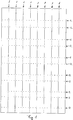
- Fig. 1 a blank of corrugated cardboard, are formed from the nine feet, which can serve in particular as feet of a cardboard transport pallet.
- first lines 1 the blank in a plurality of nine in this case, in parallel juxtaposed and in Fig. 1 Divide vertically extending stripes, weakenings and cuts are introduced into the corrugated board.
- second lines 2 which are perpendicular to the first lines 1 in Fig. 2 So horizontally - run and the first lines 1 and each of the strips mentioned in each case in the present case twelve sections, weakenings introduced.
- a wave direction of the corrugated cardboard may be parallel to the first lines 1 or parallel to the second lines 2.
- the weakenings of the corrugated cardboard along the second lines 2 are executed as perforations, which are each formed by a sequence of, for example, 8 mm long elongated cuts and standing between them webs. By these webs remain between the sections of the perforation, for example, each about 3 mm distance, the corrugated board between the cuts of the perforation can be grooved, so that said webs are thus each formed by creasing lines of a length of eg 3 mm.
- the thus weakened second lines 2 are in Fig. 1 shown as dashed lines. Instead of the perforations, continuous rill lines could also be provided as weakenings along these lines.
- the corrugated board is cut through throughout the entire section.
- the corrugated board is only weakened, in such a way that these sections can later act as breaking points.
- 1 perforations in the corrugated cardboard are introduced in these sections of the first lines, which are each formed by a sequence of elongated sections of a length of eg 8 mm and intervening grooved or unweakened webs of a width of eg 2 mm.
- the continuous cuts along the corresponding portions of the first lines 1 are in Fig. 1 shown as continuous lines, while the weakenings used to form the predetermined breaking points along the remaining portions of the first lines 1 are shown as dash-dotted lines.
- each of the first lines 1 along the respective first line 1 are each alternately with a continuous cut and a weakening provided with the single exception that the respective cut in Fig. 1 towards the top, each of the first lines 1 terminates short of one edge of the blank, while the corrugated board is only perforated in a final piece of this section about 50 mm, for example. This facilitates handling of the blank in preparation for a next process step.
- the described cuts and weakenings are introduced into the blank in a single punching operation by means of a punching tool.
- the punching tool is equipped with blades for introducing the cuts and with sequences of blades and creases for introducing the weakenings.
- the sequences of blades and creases may be in other embodiments also - especially for the weakening along the second lines 2- may also be provided exclusively Riller or - especially for generating the perforations acting as predetermined breaking points along the corresponding sections of the first lines 1- exclusively Sequences of correspondingly closely spaced blades.
- the blades may be about 8 mm long and a distance between the successive blades about 2 mm, bridged by a riller, for the weakenings along the first lines 1 and 2, respectively. be about 3 mm for the weakenings along the second lines 2.
- some of the weakenings and / or cuts may also already be introduced during manufacture of the corrugated cardboard, preferably either the weakenings and cuts along the first lines 1 or the weakenings along the second lines 2, which then expediently in Direction of transport of paper sheets used for the production of corrugated cardboard are oriented.
- only the remaining weakenings and / or cuts must be introduced after the manufacture of the corrugated board, which in turn can be done in a single punching process or even in a single embossing process - to form creasing lines.
- the blank On an upper side of the blank adhesive is applied in a next step. Then the blank becomes a four-edged one elongated winding profile 3 wrapped in Fig. 2 is shown. It is exploited that the weakenings along the second lines 2 each specify a bending line. Around these fold lines, the corrugated cardboard is bent so that each of four walls of the elongated winding profile 3 is formed by three adjacent layers of corrugated cardboard in the present embodiment.
- each of these layers is formed by each one of the sections of each of the above-mentioned strips, so that the elongated winding profile 3 forms a sequence of nine pieces in the present case, which are each formed from one of the strips and of which immediately adjacent pieces each still in the present case two of the four walls are connected by the weakened sections along the first lines 1.
- Not excluded would be a modification of the method described herein, in which the corrugated board is cut continuously into a larger number of sections of the first lines 1, so that the pieces are now still connected to one of the four walls of the elongated winding profile 3.
- the abutting layers of the elongated winding profile 3 are joined together by the previously applied adhesive.
- the said pieces of the winding profile 3 are separated in a further process step, in a very practical way by breaking the elongated winding profile 3 along the weakened portions of the first lines acting as predetermined breaking points 1. Two of three already broken and thereby isolated pieces of the elongated winding profile in Fig. 2 shown on the left.
- each of said pieces of the elongated winding profile 3 now forms a foot 4.
- One of these feet is in Fig. 3 shown.
- the described production of the feet 4 results in that each of the feet 4 is formed by a winding profile - namely a part of the elongated winding profile 3 - which is held together by the adhesive applied before the winding of the blank and which is formed from a strip of corrugated cardboard which is folded around a plurality of creases perpendicular to a longitudinal direction of the strip and wound such that each of four walls 5 of the wrapping profile, each delimited by two out of four edges of the wrapping profile, is formed by three adjacent layers of corrugated cardboard is.
- Each of these layers is formed by one of twelve sections of the strip, these portions being bounded respectively by two of the crease edges or by one of the crease edges and one of two ends of the strip.
- the creases correspond to sections of the second lines 2 and show accordingly still the weakenings introduced there.
- the foot 4 forming winding profile as the elongated winding profile 3 has a rectangular cross-section.
- Fig. 4 components of a Transortpalette, namely except the nine feet 4, an upper layer 6 and a lower layer 7, both of which are each formed from a blank of corrugated cardboard and together form a supporting bottom of the transport pallet, on the underside of the feet 4 are attached , Completed by the bonding of the two layers 6 and 7 and by fixing the feet 4 transport pallet is in Fig. 5 displayed.
- the nine feet 4 are arranged in three rows.
- the lower layer 7 has recesses, each receiving an upper end of the feet 4 fit.
- the feet 4 are inserted into these rectangular recesses so that an upper edge of each of the feet 4 bears against an underside of the upper layer 6, where the feet 4 are glued.
- the walls 5 of the feet 4 forming winding profiles are perpendicular to the bottom of the transport pallet, that is oriented perpendicular to the layers 6 and 7, and in each case parallel to an edge of the bottom.
- the recesses for the feet 4 in the lower layer 7 are formed by punched-out flaps 8. These flaps 8 are each connected via a bending edge, which is determined by a score line in the corresponding blank, connected to the lower layer 7 and folded down from the lower layer 7.
- the corrugated board of the two layers 6 and 7 have different wave directions, so that a corrugation direction of the corrugated cardboard of the top layer 6 is e.g. is oriented perpendicular to a wave direction of the corrugated cardboard of the lower layer 7, wherein both wave directions can be selected parallel to edges of the bottom.
- the two layers 6 and 7 may also be formed integrally from a single blank of corrugated cardboard together, the upper layer 6 via a Crease line is connected to the lower layer 7, wherein the blank is folded around this bend line, so that the upper layer 6 is placed on top of the lower layer 7.
- Fig. 6 are components of a similarly constructed transport pallet made of corrugated cardboard shown. Recurring features are here again and also provided in the following figures with the same reference numerals, without being described again in detail in each case.
- the transport pallet differs Fig. 5 only in that the bottom between the upper layer 6 and the lower layer 7 has three more layers 9, which are also each formed from a rectangular blank of corrugated cardboard and that the recesses are completely punched out for the feet, so that the flaps missing here, whereby not only the middle recess, but also the eight remaining, lying closer to the edge of the bottom recesses are surrounded by corrugated cardboard of the lower layer 7, so not directly on the edge of the lower layer 7.
- FIG. 7 is a plan view of a bottom of a similarly constructed transport pallet shown, in which the upper layer 6 and here hidden by the upper layer 6 and therefore invisible lower layer 7 are formed from a single blank of corrugated cardboard, the lower layer 7 by a obliquely cut in the blank rectangular surface of the blank is formed, which abuts with four corners on four different sides of the blank to an edge of the blank.
- the blank from which the bottom is formed by folding is in Fig. 7 shown in dashed lines.
- the upper layer 6 is formed of four remaining, substantially triangular faces of the blank. These sub-areas, which are each connected at one edge via a bending edge with the lower layer 7, are folded upwards and placed on the lower layer 7, where they complement each other to a complete rectangle.
- the provided in the lower layer 7 recesses for the feet 4 are in Fig. 7 represented by dotted lines.
- a foot 4 is shown for a transport pallet made of corrugated cardboard, which is the same as that in Fig. 3 shown piece of which it differs only in that it has a trapezoidal cross-section.
- Fig. 9 is a longitudinal section through a transport pallet of corrugated cardboard shown, the nine feet 4 of in Fig. 8 It has the type shown and it differs from the embodiments described above in that each one of the four walls 5 of each of the feet 4 rests on the bottom of the transport pallet. In this case, the largest of the four walls 5 is inserted into a correspondingly large recess in the lower layer 7 and glued to the underside of the upper layer 6.
- the feet 4, of which in Fig. 9 only three can be seen, are oriented so that edges of the wall 5 resting against the ground, are arranged parallel to the edges of the soil.
- FIG. 10 Two blanks of corrugated cardboard are shown, forming an upper layer 6 and a lower layer 7 of a two-ply bottom for a transport pallet, which is a modification of the transport pallet of Figures 4 and 5.
- FIG. 12 The bottom of this transport pallet can be seen together with two of nine not yet used feet 4 of this transport pallet.
- four tabs 10 are punched out of the lower layer 7 of the bottom, which are each still connected via a parallel to an edge of the bottom extending buckling edge with the lower layer 7 and folded down from the lower layer 7 and around the edge be placed around the floor up to protect the edge of the soil there from a constriction by packing tapes.
- each of the tabs 10 has a parallel thereto extending further crease line around which the tab 10 is folded over and then to be right on the edge of the ground.
- Fig. 11 shows a modification of the blank for the lower layer 7, extending from the lower layer 7 of the embodiment of the Figures 10 and 12 only differs in that the recesses are completely punched out for the feet 4, so that no flaps 8 are provided for lateral application to the feet 4.
- Fig. 13 are components of another transport pallet made of corrugated cardboard, which also has nine feet 4 of in Fig. 3 having shown type.
- the bottom of the transport pallet is formed of three blanks of corrugated cardboard.
- a first of these blanks forms the upper layer 6 serving as a support surface and ends on two mutually opposite sides of the bottom in a winding profile 11 with a rectangular cross-section extending in each case below the support surface along each edge of the bottom.
- the other two blanks each form one of two further winding profiles 12 which are glued so below the upper layer 6 between and parallel to the two along the edges of the bottom extending winding profiles 11 on the support surface, that between these two other winding profiles 12th and between each one of these further winding profiles 12 and one of the two along the edges of the bottom extending winding profiles 11 a total of three parallel to these winding profiles 11 extending grooves 13 remain with a rectangular cross-section.
- the finished bottom of the transport pallet thus formed is in Fig. 13 below the components of the soil formed from the three blanks again shown in the finished state.
- Fig. 14 is shown a cross section through the transport pallet thus formed while Fig. 15 shows the finished transport pallet diagonally from below.
- FIG. 16 is a modification of the transport pallet FIGS. 13 to 15 shown, with the nine feet 4 of this transport pallet are shown separately from the bottom of the transport pallet.
- the floor is shown in an oblique view of an underside of the floor.
- This transport pallet differs only in that six additional winding profiles 14 are provided from corrugated cardboard, which have a groove 13 corresponding rectangular cross section and are glued into the grooves 13 that they fill there remaining gaps between the feet 4.
- Fig. 17 shows a view of an underside of a bottom of a transport pallet in another embodiment, in Fig. 17 above a bottom of this transport pallet and below, shown separated from the ground, nine feet 4 of this transport pallet.
- the bottom of this transport pallet, from the in Fig. 18 a cross-section is shown, has a composed of three blanks of corrugated hollow profile.
- this hollow profile On an upper side, this hollow profile has a support surface 15, on the underside a closure surface 16.
- On two opposite sides of the support surface 15 and the end surface 16 are connected by a respective side surface 17. With the support surface 15 and the end surface 16 also has this bottom two layers, even if they do not abut each other, but limit a cavity of the hollow profile.
- a first of the three blanks forms the end surface 16 and two winding profiles 11 comprising the side surfaces. Between these winding profiles 11, two downwardly open U-profiles, each formed from one of the two further blanks, are inserted from above, which terminate the support surface 15.
- the webs 18 are each formed by two layers of corrugated cardboard, namely a centrally located in the hollow profile web 18 of parts of the two U-profiles and the two other, further outboard webs 18 each by a part of the winding profiles 11 and part of a the U-profiles.
- the end surface 16 for each of the feet 4 each have a recess which is spanned by one of the webs 18, so that a lower edge of the respective web divides the recesses in two halves.
- the feet 4 of this transport pallet differ from the feet 4 of the Fig. 3 shown type in that in an upper edge of each of the feet 4, two opposing, upwardly open recesses 19 are provided.
- the feet 4 are now inserted into the recesses in the end surface 16 so that they are accurately received by the respective recess in the end face and that the recesses 19 each receive the lower edge of the web 18, which crosses the respective recess in the end surface 16 ,
- Fig. 19 shows a view of a front side of a transport pallet, which differs from the embodiment of the Figures 17 and 18 differs in that the end surface 16 and the support surface 15 are reversed, so that the support surface 15 is formed by a single blank, which also forms the winding profiles 11 with the side surfaces 17, while the two other blanks form two profiles, each one after Include open top U-profile and added to the U-profiles additional areas are added, these profiles are pushed from below between the side surfaces 17 forming winding profiles 11.
- the recesses for the feet 4 are again introduced into the end surface 16, which is composed in this case, however, and is formed by parts of the winding profiles 11 and the two other blanks.
- the two layers of each of the webs 18 are connected in this transport pallet in each case via a bent edge at the lower edge of the respective web 18 with one of these parts, which form the end surface 16.
- Fig. 20 a blank of corrugated cardboard is shown, from which a winding profile is formed, in Fig. 21 from diagonally above and in Fig. 22 shown diagonally from below.
- An in Fig. 23 Bottom of another transport pallet shown at an angle below is formed by arranging two winding profiles of this type next to one another so that side surfaces 20 of these winding profiles rest against one another.
- the two winding profiles together form a hollow profile of the soil, wherein both a bearing surface 15 and a closing surface 16 of this hollow profile are each in several parts and are formed by two winding profiles together, while each of these winding profiles form one of two side surfaces 17 of the hollow profile.
- two recesses are provided for receiving in each case one of two feet 4 of this transport pallet, wherein these recesses each extend over the two adjoining winding profiles and are spanned by three webs 18, as in Fig. 23 can be seen.
- a middle of these webs 18 is formed by the two adjoining side surfaces 20 of both winding profiles, while the other two webs 18 are formed by two adjoining faces 21 of the individual winding profiles of the soil.
- Each of these two winding profiles can each be held together by a bolt 22, which, as in Fig. 20 shown, may be cut from a part of the end surface 16 and is slid into a designated, composed of two sections slot 23 and is pushed with a groove or open recess on the web 18, which is formed by the two faces 21. So no gluing is necessary to hold the two winding profiles together.
- Fig. 20 are also recesses 24 can be seen, which are provided in the partial surfaces 21 and the side surface 20 of the respective winding profile and thus in the webs 18 and which serve to secure the feet 4, as will be described in more detail below.
- Fig. 24 shows a strip of corrugated cardboard from which one of the two identical feet 4 of the transport pallet is formed with the soil previously described.
- the feet 4 can also in this case from a common blank on the type of blank Fig. 1 be formed.
- One of these recesses 19 is in Fig. 25 shown enlarged.
- the recess 19 is tapered at the upper edge of the foot by two opposing lugs 25, wherein the lugs 25 have flat rising edges.
- Fig. 26 the bottom and the two not connected to the ground feet 4 are shown this transport pallet, whereby the two winding profiles, which together form the hollow profile of the floor, not yet firmly connected to each other, but only juxtaposed.
- the feet 4 are now, as in Fig. 27 can be seen pushed into the recesses in the end surface 16, wherein the recesses 19 are pushed over the webs 18.
- the two winding profiles of the ground namely, that the central web 18, which is formed by the side surfaces 20 of both winding profiles, of a total of four of the recesses 19 in the feet 4 is recorded.
- the noses 25 engage in the aforementioned recesses 24, whereby the feet 4 are secured to the ground and secured against slipping out. The connection of the two winding profiles is thereby secured.
- Fig. 28 shows the finished transport pallet from above.
- a first blank for a floor of this transport pallet is in Fig. 29 shown.
- This blank forms a support surface 15, two side surfaces 17 and a two-part end surface 16 of the bottom.
- the side surfaces 17 are shown by dashed lines and given by creasing lines given bending lines with the support surface 15 and one half of the end surface 16.
- four recesses for four feet 4 already described kind are provided, in the present case, two of these rectangular recesses in each of the two halves of the end surface 16th
- a further blank is shown, which consists of the same as the first blank of corrugated cardboard and from which three further layers 9 of this soil are formed.
- the further layers 9 are glued together and placed between the support surface 15 and the end surface 16, where they are wrapped by the first blank and glued to the support surface 15 and the end surface 16.
- the bottom of this transport pallet is made by the first cut Fig. 29 together with the three layers 9 from the further blank Fig. 30 educated.
- instead of the three layers 9 instead of the three layers 9, only two such layers 9 or a single further Layer 9 between the support surface 15 and the end surface 16 may be provided.
- Fig. 31 shows a strip of corrugated cardboard from which one of the four identical feet 4 of this transport pallet is formed. Also for the production of these feet 4 that already applies to the feet 4 of the embodiments described above applies accordingly.
- Each of four walls of the respective foot 4 is thus formed by two layers of the strip wound into a square in the present case. Also in this case, the feet 4 from a common blank on the type of blank Fig. 1 be formed.
- the finished feet 4 are glued from below to the bottom of the transport pallet, to the bottom of the other layers 9.
- the feet 4 are placed in the rectangular recesses in the end surface 16, which corresponds to a floor plan of the respective foot 4 and Have size.
- Fig. 32 a blank of corrugated cardboard is shown, from which a box-shaped attachment for the transport pallet is formed.
- the article has an aperture surrounding the base 26.
- This panel is formed by angling two opposing sections 27 upwardly relative to the base 26 and tongues 28 provided at each of two ends of each of these sections 27 are angled relative to the sections 27 followed by two further sections 29 of the panel placed around the tongues 28 and fixed with small projections in mating recesses on the edge of the base 26.
- the tongues 28 come to lie between two layers of the other sections 29 of the diaphragm.
- the essay Fig. 32 is fixed to the ground by laying with the base 26 on the support surface 15, which forms an upper layer of the bottom, and fixed there with four tabs 30 there. These tabs 30 are cut out of the base 26 of the essay and are folded out to fix the essay on the ground in each case by a first bending line down from the base 26 and bent around a second bending line parallel to the first bending line.
- the tabs 30 are pushed with the second bending edge first from above through slots 31 and 32, which in the Support surface 15, the other layers 9 and the end surface 16 are provided, in such a way that a folded around the second bending line upwards end of each of the tabs 30 snaps under an edge of the provided in the support surface 15 slot 31 and there by a stop for the end of the tab 30 serving edge of the slot 31 is aligned with the slots 32 in the other layers 9 and in the end surface 16 is held.
- the provided in the other layers 9 and in the end surface 16 slots 32 are made wider than the contrast narrower slot 31 in the support surface 15. This type of attachment of the essay on the bottom of the transport pallet is in Fig.
- Fig. 20 It can be seen that in the bearing surface 15 of the embodiment described above, slots 31 for attaching the essay from Fig. 32 are provided. Therefore, the essay can be off Fig. 32 in the same way on the in the FIGS. 26 and 28 recognizable bearing surface 15 of the bottom are fixed, in the manner described above of two blanks of in Fig. 20 shown type is formed. As a stop for the ends of the tabs 30 are then, however, not deviating from the last-described embodiment, not more slots 32 in lower-lying layers of the soil, but depending on the position and folding direction of the respective tab 30, for example, the side surfaces 17 or the bolt 22 and a recess adjoining the corresponding slot 31 in the side surfaces 20.
- Fig. 34 shows a formed of a cardboard blank, preferably corrugated cardboard, plate 33 which can be adhered to an underside of the feet 4 a transport pallet, for example, to the feet 4 of the basis of the FIGS. 1 to 19 described transport pallets.
- the feet 4 are arranged in three rows of three feet 4.
- the plate 33 which has a ground plan corresponding to the floor of the transport pallet is formed by three parallel first strips, each connecting the feet 4 of one of these three rows, and by two perpendicular thereto and the ends of the three first strips interconnecting second strip. If the plate 33 is glued to the bottom of the feet 4 of the transport pallet, this can easily be transported on a roller conveyor belt without the feet 4 can get between the rollers of the roller conveyor belt.
- a transport pallet formed from corrugated cardboard which has three feet 4 of a type each formed by a winding profile. These feet 4 are glued to the bottom of the transport pallet so that one of the four walls 5 of each of these winding profiles rests against the ground and that the edges formed by the creases of the strips of all of these winding profiles are oriented parallel to each other and parallel to two out of four edges of the ground.
- the winding profiles in the direction of the edges are as long as the ground itself, so that they extend in this direction over the entire length of the soil. As a result, they form three runners in Fig. 35 shown transport pallet. In the present case, these skids or the 4 forming winding profiles have a trapezoidal cross-section.
- recesses 34 are provided for receiving forklift tines. These recesses 34 make it possible to drive the bottom of the transport pallet with the tines of the fork of a forklift also in a direction perpendicular to a longitudinal direction of the runners direction.
- FIG. 36 A blank of corrugated cardboard is shown off of one of the three feet of the transport pallet Fig. 35 is formed, by winding, by the blank is folded over the dashed lines of creases, so that each of the four walls 5 of the resulting winding profile is formed by two layers of the blank.
- the bend lines are defined by Rill lines.
- An in Fig. 36 A double arrow indicates a wave direction of the corrugated board used for the cutting.
- Fig. 36 is good to see that the recesses 34 are not completely cut or punched in the opposite the bottom angled walls 5 of the feet 4 forming winding profiles.
- a similar foot 4 is shown for a transport pallet extending from the feet 4 of the Figures 35 and 36 only differs in that the recesses 34 are completely cut or punched out, so are executed without the flaps 35, and that the walls 5 each have not only two, but three layers of corrugated cardboard.
- Fig. 38 the cross-section of a transport pallet is shown, which has three such feet 4, wherein the bottom of this transport pallet has an upper layer 6, a lower layer 7 and a further layer 9 arranged therebetween.
- the lower layer 7 is formed by two strips which leave at two edges and in the middle of the bottom recesses for receiving the feet 4, in these recesses, the feet 4 are glued to the further layer 9.
- a correspondingly constructed foot 4 is shown for a transport pallet that differs from the one in FIG Fig. 37 shown foot 4 only differs by a square cross section instead of the trapezoidal cross section.
- a blank of corrugated cardboard for forming such an elongated foot, each with two recesses 34 is shown in two of four walls 5, which differs from the in Fig. 39 but differs in that each of the walls 5 is again formed in this case only by two instead of three layers of corrugated cardboard.
Landscapes
- Engineering & Computer Science (AREA)
- Mechanical Engineering (AREA)
- Pallets (AREA)
Applications Claiming Priority (2)
| Application Number | Priority Date | Filing Date | Title |
|---|---|---|---|
| DE102016003858 | 2016-03-28 | ||
| DE102016216024.9A DE102016216024A1 (de) | 2016-03-28 | 2016-08-25 | Objekt aus Pappe und Herstellungsverfahren |
Publications (2)
| Publication Number | Publication Date |
|---|---|
| EP3225563A2 true EP3225563A2 (fr) | 2017-10-04 |
| EP3225563A3 EP3225563A3 (fr) | 2017-12-06 |
Family
ID=58428135
Family Applications (1)
| Application Number | Title | Priority Date | Filing Date |
|---|---|---|---|
| EP17162889.4A Withdrawn EP3225563A3 (fr) | 2016-03-28 | 2017-03-24 | Objet en carton et procédé de fabrication |
Country Status (1)
| Country | Link |
|---|---|
| EP (1) | EP3225563A3 (fr) |
Cited By (1)
| Publication number | Priority date | Publication date | Assignee | Title |
|---|---|---|---|---|
| DE102017218820A1 (de) | 2017-10-20 | 2019-04-25 | Hans-Peter Stange | Transportpalette und Verfahren zum Herstellen einer Transportpalette |
Citations (1)
| Publication number | Priority date | Publication date | Assignee | Title |
|---|---|---|---|---|
| EP0496199A1 (fr) | 1991-01-24 | 1992-07-29 | BINI & C. S.r.l. | Palettes en carton ondulé et procédé pour leur fabrication |
Family Cites Families (14)
| Publication number | Priority date | Publication date | Assignee | Title |
|---|---|---|---|---|
| US2559930A (en) * | 1946-10-22 | 1951-07-10 | Robert Gair Co Inc | Pallet |
| US2798685A (en) * | 1953-07-24 | 1957-07-09 | Arthur G Mooney | Expendable pallet |
| US4390154A (en) * | 1981-10-01 | 1983-06-28 | Container Corporation Of America | Corrugated paperboard pallet deck |
| DE9006016U1 (de) * | 1990-05-28 | 1991-09-26 | Schröter + Bake AG, 8402 Neutraubling | Transportpalette |
| DE9104762U1 (de) * | 1991-04-18 | 1992-08-13 | Schröter + Bake AG, 8402 Neutraubling | Bausatz für einen Warenbehälter |
| JPH0656154A (ja) * | 1992-05-21 | 1994-03-01 | Chiyoda Container- Kk | 段ボ−ルパレット用支柱 |
| US5603258A (en) * | 1993-12-17 | 1997-02-18 | The Servant's Inc. | Corrugated pallet |
| US5465672A (en) * | 1994-05-16 | 1995-11-14 | Down River International, Inc. | Wrapped deck pallet |
| US5441154A (en) * | 1994-06-28 | 1995-08-15 | Youell, Iii; Donald R. | Integrated paperboard container and pallet system |
| JPH0939968A (ja) * | 1995-08-01 | 1997-02-10 | Oji Paper Co Ltd | 紙製パレット用支持脚 |
| US6070726A (en) * | 1998-08-03 | 2000-06-06 | Graham Creative Packaging | Pallet and container including pallet |
| EP1122179A1 (fr) * | 2000-02-03 | 2001-08-08 | Brakemann Verpackungen GmbH & Co.KG | Corps formé par enroulement de carton ondulé |
| FI117595B (fi) * | 2004-04-06 | 2006-12-15 | Suomen Kuitulava Oy | Menetelmä kuormaa kantavien elementtien valmistamiseksi |
| CN201209035Y (zh) * | 2008-04-09 | 2009-03-18 | 谭亚特 | 纸栈板 |
-
2017
- 2017-03-24 EP EP17162889.4A patent/EP3225563A3/fr not_active Withdrawn
Patent Citations (1)
| Publication number | Priority date | Publication date | Assignee | Title |
|---|---|---|---|---|
| EP0496199A1 (fr) | 1991-01-24 | 1992-07-29 | BINI & C. S.r.l. | Palettes en carton ondulé et procédé pour leur fabrication |
Cited By (1)
| Publication number | Priority date | Publication date | Assignee | Title |
|---|---|---|---|---|
| DE102017218820A1 (de) | 2017-10-20 | 2019-04-25 | Hans-Peter Stange | Transportpalette und Verfahren zum Herstellen einer Transportpalette |
Also Published As
| Publication number | Publication date |
|---|---|
| EP3225563A3 (fr) | 2017-12-06 |
Similar Documents
| Publication | Publication Date | Title |
|---|---|---|
| DE69228192T2 (de) | Wellpappe-palette | |
| EP2028115B1 (fr) | Présentoir, flan et procédé de sa fabrication | |
| DE102015012066A1 (de) | Transportpalette, Modul und Faltbogen dafür sowie Verfahren zum Herstellen einer Transportpalette | |
| DE2732675A1 (de) | Fuer palettentransport bestimmte kiste oder container | |
| WO2006122539A1 (fr) | Decoupe de carton destinee a la production d'un coin d'emballage et coin d'emballage | |
| EP1651533B1 (fr) | Cageot a plusieurs cavites | |
| EP3225563A2 (fr) | Objet en carton et procédé de fabrication | |
| DE69727068T2 (de) | Palette sowie verfahren zu deren herstellung | |
| DE102016222955B4 (de) | Regal aus Pappe und Herstellungsverfahren | |
| DE102016216024A1 (de) | Objekt aus Pappe und Herstellungsverfahren | |
| WO1986005159A1 (fr) | Cageot | |
| DE68908428T2 (de) | Schalenförmige Verpackung aus Karton oder dergleichen. | |
| EP3323322A1 (fr) | Étagère en carton | |
| DE29513265U1 (de) | Teilbare Verpackung aus Wellpappe oder Karton | |
| DE10335201B4 (de) | Stabilisierungssteg an einer Mehrlochsteige | |
| EP3888501B1 (fr) | Élément socle pliant | |
| DE102019208796B4 (de) | Verbindungsmechanismus und möbelstück aus pappe | |
| DE102017218820A1 (de) | Transportpalette und Verfahren zum Herstellen einer Transportpalette | |
| DE10356825A1 (de) | Stapelbarer Transportbehälter aus Wellpappe und Zuschnitt dafür | |
| DE10341879A1 (de) | Mehrlochsteige | |
| DE29708219U1 (de) | Vorrichtung aus Wellpappe zur Unterstützung von Lasten | |
| DE102004021023A1 (de) | Mehrlochsteige | |
| DE29918040U1 (de) | Stapelbare Faltschachtel | |
| DE20306640U1 (de) | Zuschnitt für eine Palette sowie eine derartige Palette | |
| DE29622634U1 (de) | Steigenähnliche Verpackung |
Legal Events
| Date | Code | Title | Description |
|---|---|---|---|
| PUAI | Public reference made under article 153(3) epc to a published international application that has entered the european phase |
Free format text: ORIGINAL CODE: 0009012 |
|
| AK | Designated contracting states |
Kind code of ref document: A2 Designated state(s): AL AT BE BG CH CY CZ DE DK EE ES FI FR GB GR HR HU IE IS IT LI LT LU LV MC MK MT NL NO PL PT RO RS SE SI SK SM TR |
|
| AX | Request for extension of the european patent |
Extension state: BA ME |
|
| PUAL | Search report despatched |
Free format text: ORIGINAL CODE: 0009013 |
|
| AK | Designated contracting states |
Kind code of ref document: A3 Designated state(s): AL AT BE BG CH CY CZ DE DK EE ES FI FR GB GR HR HU IE IS IT LI LT LU LV MC MK MT NL NO PL PT RO RS SE SI SK SM TR |
|
| AX | Request for extension of the european patent |
Extension state: BA ME |
|
| RIC1 | Information provided on ipc code assigned before grant |
Ipc: B65D 19/34 20060101AFI20171027BHEP Ipc: B65D 19/40 20060101ALI20171027BHEP |
|
| STAA | Information on the status of an ep patent application or granted ep patent |
Free format text: STATUS: THE APPLICATION IS DEEMED TO BE WITHDRAWN |
|
| 18D | Application deemed to be withdrawn |
Effective date: 20180607 |