EP3225564B1 - Schaumspendebehälter - Google Patents
Schaumspendebehälter Download PDFInfo
- Publication number
- EP3225564B1 EP3225564B1 EP15863617.5A EP15863617A EP3225564B1 EP 3225564 B1 EP3225564 B1 EP 3225564B1 EP 15863617 A EP15863617 A EP 15863617A EP 3225564 B1 EP3225564 B1 EP 3225564B1
- Authority
- EP
- European Patent Office
- Prior art keywords
- foam
- outlet
- dispensing
- opened
- liquid agent
- Prior art date
- Legal status (The legal status is an assumption and is not a legal conclusion. Google has not performed a legal analysis and makes no representation as to the accuracy of the status listed.)
- Active
Links
Images









Classifications
-
- B—PERFORMING OPERATIONS; TRANSPORTING
- B05—SPRAYING OR ATOMISING IN GENERAL; APPLYING FLUENT MATERIALS TO SURFACES, IN GENERAL
- B05B—SPRAYING APPARATUS; ATOMISING APPARATUS; NOZZLES
- B05B1/00—Nozzles, spray heads or other outlets, with or without auxiliary devices such as valves, heating means
- B05B1/02—Nozzles, spray heads or other outlets, with or without auxiliary devices such as valves, heating means designed to produce a jet, spray, or other discharge of particular shape or nature, e.g. in single drops, or having an outlet of particular shape
-
- A—HUMAN NECESSITIES
- A47—FURNITURE; DOMESTIC ARTICLES OR APPLIANCES; COFFEE MILLS; SPICE MILLS; SUCTION CLEANERS IN GENERAL
- A47K—SANITARY EQUIPMENT; ACCESSORIES THEREFOR, e.g. TOILET ACCESSORIES
- A47K5/00—Holders or dispensers for soap, toothpaste or the like
- A47K5/06—Dispensers for soap
- A47K5/12—Dispensers for soap for liquid or pasty soap
- A47K5/1202—Dispensers for soap for liquid or pasty soap dispensing dosed volume
- A47K5/1204—Dispensers for soap for liquid or pasty soap dispensing dosed volume by means of a rigid dispensing chamber and pistons
- A47K5/1205—Dispensing from the top of the dispenser with a vertical piston
-
- A—HUMAN NECESSITIES
- A47—FURNITURE; DOMESTIC ARTICLES OR APPLIANCES; COFFEE MILLS; SPICE MILLS; SUCTION CLEANERS IN GENERAL
- A47K—SANITARY EQUIPMENT; ACCESSORIES THEREFOR, e.g. TOILET ACCESSORIES
- A47K5/00—Holders or dispensers for soap, toothpaste or the like
- A47K5/06—Dispensers for soap
- A47K5/12—Dispensers for soap for liquid or pasty soap
- A47K5/1217—Electrical control means for the dispensing mechanism
-
- A—HUMAN NECESSITIES
- A47—FURNITURE; DOMESTIC ARTICLES OR APPLIANCES; COFFEE MILLS; SPICE MILLS; SUCTION CLEANERS IN GENERAL
- A47K—SANITARY EQUIPMENT; ACCESSORIES THEREFOR, e.g. TOILET ACCESSORIES
- A47K5/00—Holders or dispensers for soap, toothpaste or the like
- A47K5/14—Foam or lather making devices
-
- B—PERFORMING OPERATIONS; TRANSPORTING
- B05—SPRAYING OR ATOMISING IN GENERAL; APPLYING FLUENT MATERIALS TO SURFACES, IN GENERAL
- B05B—SPRAYING APPARATUS; ATOMISING APPARATUS; NOZZLES
- B05B11/00—Single-unit hand-held apparatus in which flow of contents is produced by the muscular force of the operator at the moment of use
- B05B11/01—Single-unit hand-held apparatus in which flow of contents is produced by the muscular force of the operator at the moment of use characterised by the means producing the flow
- B05B11/10—Pump arrangements for transferring the contents from the container to a pump chamber by a sucking effect and forcing the contents out through the dispensing nozzle
- B05B11/1001—Piston pumps
-
- B—PERFORMING OPERATIONS; TRANSPORTING
- B05—SPRAYING OR ATOMISING IN GENERAL; APPLYING FLUENT MATERIALS TO SURFACES, IN GENERAL
- B05B—SPRAYING APPARATUS; ATOMISING APPARATUS; NOZZLES
- B05B11/00—Single-unit hand-held apparatus in which flow of contents is produced by the muscular force of the operator at the moment of use
- B05B11/01—Single-unit hand-held apparatus in which flow of contents is produced by the muscular force of the operator at the moment of use characterised by the means producing the flow
- B05B11/10—Pump arrangements for transferring the contents from the container to a pump chamber by a sucking effect and forcing the contents out through the dispensing nozzle
- B05B11/1042—Components or details
- B05B11/1043—Sealing or attachment arrangements between pump and container
- B05B11/1045—Sealing or attachment arrangements between pump and container the pump being preassembled as an independent unit before being mounted on the container
-
- B—PERFORMING OPERATIONS; TRANSPORTING
- B05—SPRAYING OR ATOMISING IN GENERAL; APPLYING FLUENT MATERIALS TO SURFACES, IN GENERAL
- B05B—SPRAYING APPARATUS; ATOMISING APPARATUS; NOZZLES
- B05B11/00—Single-unit hand-held apparatus in which flow of contents is produced by the muscular force of the operator at the moment of use
- B05B11/01—Single-unit hand-held apparatus in which flow of contents is produced by the muscular force of the operator at the moment of use characterised by the means producing the flow
- B05B11/10—Pump arrangements for transferring the contents from the container to a pump chamber by a sucking effect and forcing the contents out through the dispensing nozzle
- B05B11/1042—Components or details
- B05B11/1043—Sealing or attachment arrangements between pump and container
- B05B11/1046—Sealing or attachment arrangements between pump and container the pump chamber being arranged substantially coaxially to the neck of the container
-
- B—PERFORMING OPERATIONS; TRANSPORTING
- B05—SPRAYING OR ATOMISING IN GENERAL; APPLYING FLUENT MATERIALS TO SURFACES, IN GENERAL
- B05B—SPRAYING APPARATUS; ATOMISING APPARATUS; NOZZLES
- B05B7/00—Spraying apparatus for discharge of liquids or other fluent materials from two or more sources, e.g. of liquid and air, of powder and gas
- B05B7/0018—Spraying apparatus for discharge of liquids or other fluent materials from two or more sources, e.g. of liquid and air, of powder and gas with devices for making foam
- B05B7/0025—Spraying apparatus for discharge of liquids or other fluent materials from two or more sources, e.g. of liquid and air, of powder and gas with devices for making foam with a compressed gas supply
- B05B7/0031—Spraying apparatus for discharge of liquids or other fluent materials from two or more sources, e.g. of liquid and air, of powder and gas with devices for making foam with a compressed gas supply with disturbing means promoting mixing, e.g. balls, crowns
- B05B7/0037—Spraying apparatus for discharge of liquids or other fluent materials from two or more sources, e.g. of liquid and air, of powder and gas with devices for making foam with a compressed gas supply with disturbing means promoting mixing, e.g. balls, crowns including sieves, porous members or the like
-
- A—HUMAN NECESSITIES
- A47—FURNITURE; DOMESTIC ARTICLES OR APPLIANCES; COFFEE MILLS; SPICE MILLS; SUCTION CLEANERS IN GENERAL
- A47K—SANITARY EQUIPMENT; ACCESSORIES THEREFOR, e.g. TOILET ACCESSORIES
- A47K5/00—Holders or dispensers for soap, toothpaste or the like
- A47K5/14—Foam or lather making devices
- A47K5/16—Foam or lather making devices with mechanical drive
-
- B—PERFORMING OPERATIONS; TRANSPORTING
- B05—SPRAYING OR ATOMISING IN GENERAL; APPLYING FLUENT MATERIALS TO SURFACES, IN GENERAL
- B05B—SPRAYING APPARATUS; ATOMISING APPARATUS; NOZZLES
- B05B7/00—Spraying apparatus for discharge of liquids or other fluent materials from two or more sources, e.g. of liquid and air, of powder and gas
- B05B7/0018—Spraying apparatus for discharge of liquids or other fluent materials from two or more sources, e.g. of liquid and air, of powder and gas with devices for making foam
- B05B7/005—Spraying apparatus for discharge of liquids or other fluent materials from two or more sources, e.g. of liquid and air, of powder and gas with devices for making foam wherein ambient air is aspirated by a liquid flow
Definitions
- the foam dispensing container 100 of this embodiment has a container body 40 that reserves a liquid agent L, a head part 30 having an outlet 20, and a dispensing operation part (pump head part 32) .
- the head part 30 dispenses the liquid agent L delivered from the container body 40 through the outlet 20 into foam.
- the dispensing operation part (pump head part 32) allows dispensing of a predetermined amount of foamy liquid agent (foam B) through the outlet 20, each time it accepts a user's operation. In this way, the foam object FB with a desired intended shape as illustrated in FIG. 3A is built.
- the foam dispensing container 100 is a container capable of dispensing the liquid agent L from the container body 40, upon being actuated mechanically or electrically.
- the foam dispensing container 100 is composed of the container body 40 that reserves the liquid agent L, and a nozzle assembly 50 (foam delivery mechanism 50) that is attached to the container body 40 and is used for dispensing the liquid agent L.
- the outlet 20 is an opening through which the form B is dispensed outside the foam dispensing container 100.
- the head part 30 is a term collectively denoting portions that form a flow channel of the liquid agent L or foam B outside the container body 40, and encompsses the outlet 20.
- the head part 30 has embossed on the top face thereof a pattern indication 15 that corresponds to the intended shape of the foam object FG (see FIG. 3A ) built up with the dispensed foam B seen in a plan view.
- a musical note symbol (eighth note) is illustrated as an example of the intended shape of the foam object FB. The user can easily discriminate, at a glance, a plurlaity of types of the foam dispensing containers 100 whose geometries of the outlets 20 are different.
- the linear form is preferably a contiguous long shape, but the linear form is not limited thereto, and also includes embodiments having a plurality of discrete elements (openings) closely juxtaposed in the longitudinal direction, which are exemplified by the forms of broken line and chain line. More specifically, unlike the container of Patent Literature 1 by which an intended shape is stippled by using a pluarlity of outlets distributed two-dimensionally, the outlet 20 of this embodiment draws at least a part of the intended shape like a line drawing, by aid of the contiguous geometry that contains a long linear portion. Such linear portion may be a contiguous opening, or may be discrite openings arranged in line.
- the term "linear” will be used to encompass a mode representing a continuous line, and a mode representing discrete elements arranged in line to give a broken line, chain line and so forth.
- the phrase stating that "the outlet 20 has a contiguous geometry narrowed from the intended shape” means that linear portions of the outlet 20 are arranged along the contour of the intended shape, or so as to fill the inside of the intended shape, for the purpose of building up the intended shape using the foam B that swells after dispensed.
- the outlet 20 may be given as an opening with an integrated contiguous geometry.
- each of a plurality of partial outlets has a contiguous geometry, and these partial outlet may be combined to give the outlet 20.
- Each of the outlets 20 according to this embodiment and the later-described first to third modified examples is integrally formed.
- the outlet 20 according to the fourth modified example is configured by combining narrowly-opened parts 22a, 22b which correspond to the partial outlet.
- the outlet 20 of this embodiment has a linear narrowly-opened part 22 and a widely-opened part 24 made wider than the narrowly-opened part 22.
- the widely-opened part 24 is formed contiguously with the narrowly-opened part 22.
- the outlet 20 is formed to have a contiguous geometry participated by the narrowly-opened part 22 and the widely-opened part 24.
- the linear narrowly-opened part 22 may be a contiguous long opening as described above, or may be discrete openings arranged in line.
- the narrowly-opened part 22 may have a form of constant-width band, or may have a width that varies in the longitudinal direction.
- Extention style of the narrowly-opened part 22 may be straight, curved, or bent, without special limitation.
- the narrowly-opened part 22 in this embodiment is composed of a plurality of narrowly-opened parts 22a, 22b which are bent and mutually connected. As described later, the narrowly-opened part 22a has a straight form, meanwhile the narrowly-opened part 22b has a curved form.
- the outlet 20 is formed with the contiguous geometry, so that the dispensed foam B swells on the palm H which is the dispensing target plane, solely in the width direction of the outlet 20, and builds up the foam object FB substantially without expansion in the longitudinal direction. Accordingly, a desired foam object FB with intended shape may be built up only with a small amount of foam B. Owing to the suppressed difference of height within the foam object FB, such desired intended shape will be well-profiled in a plan view.
- FIG. 4 is a side elevation of the nozzle assembly 50 including the head part 30.
- FIG. 5 is a plan view of the head part 30.
- FIG. 6 is a cross-sectional view taken along line VI-VI in FIG. 5 , showing a sectional side elevation of the head part 30.
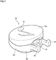
- FIG. 7 is a perspective view of a foam dispenser attachment 10.
- the ball valve 59 is a valve that prevents fall of the liquid agent L having been reserved in the housing 56 and the suction tube 57.
- the pump head part 32 (dispensing operation part) of the head part 30 the piston 55 increases air pressure in the housing 56, while restricting the ball valve 59 from ascending (opened) with the lower end of the piston 55.
- the piston 55 has provided thereto a liquid flow channel (not illustrated), which is a small hole that communicates the housing 56 with the head part 30.
- the air pressure in the housing may be elevated by pressing the pump head part 32 down powerfully, and the liquid agent L is then pushed from the housing 56 up into the head part 30.
- the head part 30 has provided thereto an air flow channel (not illustrated) that is communicated with the outside.
- the head part 30 has provided therein an air-liquid contact portion 51 on the flow channel for the liquid agent L.
- the air-liquid contact portion 51 is typically a mesh, which transforms the liquid agent L into foam (foam B), by allowing the air outside the head part 30 and the air in the housing 56, together with the liquid agent L, to pass through the air-liquid contact portion 51 (mesh) .
- the foam B is dispensed through the outlet 20 of the head part 30.
- the spring 58 elastically returns the piston 55 to the original position.
- the pressure inside the housing 56 becomes low, the ball valve 59 is opened, and a new portion of the liquid agent L is sucked up into the suction tube 57 to fill the housing 56 again.
- the inside of the head part 30 is kept at the atmospheric pressure with the outer air introduced through the air flow channel into the head part 30.
- nozzle assembly 50 The above-described structure and operation of the nozzle assembly 50 are merely examples, and also well-known ones, such as a foam dispenser described in Patent Literature 4 described above, may be used.
- a predetermined amount of foam B is dispensed through the outlet 20, each time the pump head part 32 (dispensing operation part) is operated.
- the predetermined amount is determined by parameters such as stroke in reciprocating motion of the piston 55.
- the foam dispenser attachment 10 is used while being detachably attached to the nozzle part 52 of the foam dispensing container 100.
- the foam dispenser attachment 10 has the outlet 20, and when detachably attached to the nozzle part 52, the outlet 20 communicates with the nozzle opening 54. More specifically, the foam dispenser attachment 10 of this embodiment has the outlet 20 with the contiguous geometry narrowed from the intended shape, catches the foamy liquid agent (foam B) dispensed from the nozzle opening 54, and dispenses it through the outlet 20 to build up the foam object FB with intended shape.
- foam B foamy liquid agent
- a plurality of types of foam dispenser attachments 10 having different opening geometries of the outlet 20 may be attached to the nozzle part 52 in an exchangeable manner.
- the foam object FB with intended shape may be built up by dispensing, while using the container body 40 and the nozzle assembly 50 in common.
- the common foam dispenser attachment 10 may be attached to the nozzel assemblies 50 of different container bodies 40 in an exchangeable manner. Accordingly, if the container body 40 and the nozzle assembly 50 should be discarded or exchanged, the foam dispenser attachment 10 may be used consecutively, and the foam dispenser attachment 10 may be attached afterward to the container body 40 and the nozzle assembly 50 having widely been put into practical use.
- the foam dispenser attachment 10 has a fitting part 16 to which the nozzle opening 54 is inserted, and an engagement part 18 that detachably engages with the nozzle part 52.
- the fitting part 16 of the foam dispenser attachment 10 is an opening with a geometry corresponded to the outer profile of the nozzle part 52 of the nozzle assembly 50, and allows the nozzle part 52 to be tightly fitted thereto.
- geometry of the engagement part 18 is not specifically limited, the engagement part 18 in this embodiment is a claw-like projection that projects upward, and is provided in a pair on both sides of the fitting part 16.
- the pump head part 32 in this embodiment has an umbrella-like shape, and the circumference 33 of the pump head part 32 suspends downward.
- the engagement part 18 of the foam dispenser attachment 10 engages with the circumference 33 of the pump head part 32, particularly on both sides of the nozzle part 52. In this way, the foam dispenser attachment 10 attached to the pump head part 32 may be prevented from inclining in the front-rear direction and in the crosswise direction relative to the pump head part 32. The foam dispenser attachment 10 is therefore unlikely to contingently incline or detach, even if the foam B is jetted powerfully through the nozzle part 52 into the foam dispenser attachment 10 by the press-down operation made on the pump head part 32.
- the head part 30 has a reservoir 60 that reserves the foamy liquid agent (foam B) delivered from the container body 40.
- the reservoir 60 is a void that decelerates the foamy liquid agent (foam B) delivered from the container body 40 through the nozzle part 52, and feeds the foam B so as to be distributed over the sunt portion of the outlet 20.
- the reservoir 60 is arranged on the flow channel of the foam B, between the nozzle opening 54 of the nozzle part 52 and the outlet 20, whose flow channel is made wider than the nozzle opening 54 and the outlet 20.
- the reservoir 60 in this embodiment is formed inside the foam dispenser attachment 10 that constitutes the head part 30, and between the outlet 20 and the fitting part 16.
- the foam B delivered from the container body 40 is temporalily reserved in the reservoir 60, and then uniformly dispensed downward over the entire portion of the outlet 20.
- the foam B is therefore prevented from being dispensed predominantly on the front end side (the lefthand side in FIG. 6 ) of the outlet 20 in the feeding direction of the foam B, but instead dispensed uniformly through the entire portion of the outlet 20.
- the foam B delivered from the container body 40 tends to decelerate inside the reservoir 60 particularly on the front end side thereof, and to stagnate therein.
- the reservoir 60 in this embodiment has the ceiling 66 that declines towards the outlet 20, so that the foam B that is delivered from the container body 40 and collides on the ceiling 66 turns the direction towards the outlet 20.
- the foam B having been delivered from the container body 40 to the foam dispenser attachment 10 is prevented from excessively stagnating in the front end side of the reservoir 60, and thus can be smoothly dispensed through the outlet 20.
- the internal height of the outlet 20 decreases towards the front end side of the feeding direction of foam B, or, towards the distal side away from the nozzle opening 54, the foam B decelerated inside the reservoir 60 is prevented from stagnating in the front end side of the reservoir 60.
- the head part 30 of the foam dispensing container 100 has the nozzle part 52.
- the nozzle part 52 of this embodiment dispenses the foamy liquid agent (foam B), delivered from the container body 40, obliquely downward inside the reservoir 60.
- the head part 30 (the foam dispenser attachment 10 in this embodiment) has an inclined face 62 that nearly confronts such obliquely downward direction.
- the inclined face 62 is provided inside the reservoir 60, and is formbed between the wide guide part 28 and the narrow guide part 27.
- the outlet 20 is formed so as to extend between the front end side and the base side of the inclined face 62 (see FIG. 10 ).
- the base side of the foam dispenser attachment 10 which is in proximity to the fitting part 16, is a portion where the foam B jetted through the nozzle opening 54 tends to pass the outlet, and is less likely to dispense the foam B as compared with the front end side.
- the inclined face 62 inside the reservoir 62 as in this embodiment to decelerate the foam B, the amount of dispensed foam B may be made uniform over the front end side and the base side of the outlet 20.
- the dispensing guide 26 is provided so as to extend downward from the reservoir 60.
- the foam B having been decelerated inside the reservoir 60 and once reserved therein, flows into the dispensing guide 26, guided downward, and dispensed through the outlet 20.
- the foam B dispensed through the outlet 20 is reduced to swell. More specifically, the foam B has a lower bulk density and is highly compressive as compared with the liquid agent L in the liquid form, and thereby the foam B delivered through the nozzle opening 54 to the reservoir 60 and reserved there is compressed. For this reason, the foam B largely swells if the length of passage of the dispensing guide 26 is short.
- the foam B is gradually depressurized as it passes through the dispensing guide 26, and is also rectified during passage through the dispensing guide 26. This advantageously stabilizes the shape of the dispensed foam B, and suppresses the dispensed foam B from swelling, so that the foam object FB with intended shape will be built up in a finely profiled manner.
- the internal bottom face 64 of the reservoir 60 is made higher in the front end side (internal bottom face 64b), than in the base side (internal bottom face 64a) of the inclined face 62 (see also FIG. 8 ).
- the dispensing guide 26 has the upper end defined by the internal bottom face 64 of the reservoir 60, and has the lower end defined by the outlet 20. Accordingly, the height at which the dispensing guide 26 starts (upper end height) is lower than the inclined face 62 on the base side, and higher than the inclined face 62 on the front end side.
- the outlet 20 is formed so as to lie horizontally at the bottom end of the dispensing guide 26.
- the path length of the dispensing guide 26 (vertical length in FIG.
- the outlet 20 of this embodiment is designed to allow a larger amount of foam B to pass through the widely-opened part 24 formed on the front end side of the reservoir 60 as described later.
- the head part 30 may have inside thereof a net body (not illustrated) through which the foamy liquid agent L delivered from the container body 40 is allowed to pass.
- a net body (not illustrated) through which the foamy liquid agent L delivered from the container body 40 is allowed to pass.
- the position of placement of the net body is not spesifically limited, it is preferable to place at least a part of the net body inside the dispensing guide 26, or adjacent to the dispensing guide 26. In particular, the net body is preferably placed in the vicinity of the outlet 20.
- the liquid agent L is prevented from dripping, even if the dispensing direction of foam B should be downward like in this embodiment. More specifically, while the liquid agent L in the state of foam B may otherwise return back to the liquid form with time due to collapse of bubbles, the net body provided close to the outlet 20 will help the liquid agent L in the liquid form adhere thereon, and prevent the liquid agent L from dripping from the outlet 20. Since the foam B passes through the net body immediately before being dispensed through the outlet 20, a further fine-bubbled foam may be produced.
- the net body is a mesh or other porous body.
- the net body may be a mesh obtained by weaving warps and wefts, made of metal or resin, into plain weave or twilled weave (woven wire net), or may be a perforated screen plate obtained by perforating a sheet-like base to form therein a large number of fine throughholes.
- the opening of the net body may be set larger than the opening of the air-liquid contact portion 51. With such setting, pressure loss at the net body may be reduced, and thereby the pressing force on the pump head part 32, necessary for dispensing the foam B through the outlet 20, is prevented from excessively increasing.
- the net body may be placed on the base side of the feeding direction of the liquid agent L, relative to the outlet 20.
- the net body may be placed so as to cover the entire portion of the outlet 20 that is composed of the widely-opened part 24 and the narrowly-opened parts 22a, 22b.
- a part of the net body may be placed so as to extend over the internal bottom face 64a and the inclined face 62 illustrated in FIG. 6 .
- Other part of the net body may be positioned inside the dispensing guide 26, particularly near the lower end thereof adjoining to the outlet 20 (widely-opened part 24). Note however that, as an alternative to the above-described embodiment, the net body may be placed so as to cover the widely-opened part 24 only, without placing it over the narrowly-opened parts 22a, 22b.
- the foam object FB with intended shape may be built up while avoiding shortage of the foam B to be fed to the narrowly-opened parts 22a, 22b, and while preventing dripping from the outlet 20.
- FIG. 8A is a top perspective view of an upper half 10a of the foam dispenser attachment 10
- FIG. 8B is a top perspective view of a lower half 10b
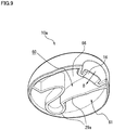
- FIG. 9 is a bottom perspective view of the upper half 10a.
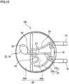
- FIG. 10 is a plan view of the lower half 10b.
- the foam dispenser attachment 10 is configured by mutually combining the upper half 10a and the lower half 10b in the dispensing direction.
- the lower half 10b has the outlet 20 formed so as to open therein. This configuration facilitates formation of the reservoir 60 that has the inclined face 62 and an inner guide 29 described later, inside the foam dispenser attachment 10.
- the upper half 10a and the lower half 10b may be joined unseparably, typically by using an adhesive.
- the upper half 10a and the lower half 10b may be formed typically by injection molding of a synthetic resin.
- the outlet 20 has the linear narrowly-opened part 22, and the widely-opened part 24 that is formed contiguously with the narrowly-opened part 22 and is made wider than the narrowly-opened part 22.
- the widely-opened part 24 is placed on the front end side of the inclined face 62, and the thenarrowly-opened part 22 is placed on the base side.
- the dispensing guide 26 has a narrow guide part 27 formed to oppose by sandwiching the narrowly-opened part 22, and a wide guide part 28 disposed along the widely-opened part 24.
- the narrow guide part 27 and the wide guide part 28 communicate with each other while bounded nearly by the width of the narrow guide part 27.
- the outlet 20 of this embodiment has a straight narrowly-opened part 22a that corresponds to the stem of eighth note, a curved narrowly-opened part 22b that corresponds to the flag, and a widely-opened part 24 that corresponds to the head.
- the dispensing guide 26 is formed so as to surround the circumference of the outlet 20 in a plan view as illustrated in FIG. 10 .
- the foam object FB with intended shape, modeld after a musical note (eighth note) as illustrated in FIG. 3A may be built up by dispensing.
- the foam B dispensed through the narrowly-opened parts 22a, 22b build the narrow portion NP of the foam object FB, meanwhile the foam B dispensed through the widely-opened part 24 builds the wide foam portion WP of the foam object FB.
- the narrow guide part 27 and the wide guide part 28 communicate with each other while bounded nearly by the width of the narrow guide part 27, the width of the foam object FB abruptly changes at the boundary of the wide foam portion WP and the narrow portion NP.
- the widely-opened part 24 is disposed on the front end side (the lefthand side in FIG. 10 ) of the foam dispenser attachment 10, and the narrowly-opened parts 22a and 22b are disposed on the the base side (the righthand side in FIG. 10 ) closer to the fitting part 16.
- the path length of the dispensing guide on the front end side of the foam dispenser attachment 10 is made longer than the path length of the dispensing guide on the base end side, so that the foam B after passed through the widely-opened part 24 is suppressed from swelling.
- the wide foam portion WP of the foam object FB illustrated in FIG. 3A is prevented from excessively swelling, so that the foam object FB with the desired intended shape may be built up even if the amount of diespensed foam B should vary to some extent.
- the plurality of linear narrowly-opened parts 22a, 22b of the outlet 20 in this embodiment cross each other.
- the cuved narrowly-opened part 22b that corresponds to the flag of musical note (eighth note) crosses near the end of the straight narrowly-opened part 22a that corresponds to the stem of the note, more specifically crosses at a position slightly set back inwardly from the terminal end.
- Such intersection will have a relatively large amount of dispensed foam B since the foam B came from the narrowly-opened parts 22a and 22b will combine there.
- the dispensed foam object FB will be built up as if the flag of eighth note is joined to the very end of the stem.
- inner guides 29b are provided so as to extend vertically.
- the inner guides 29b are provided on both sides of the narrow guide part 27.
- the upper half 10a of the foam dispenser attachment 10 has an inner guide 29a.
- the inner guide 29a surrounds, in a plan view, at least a part of the circumference of the outlet 20 (see FIG. 10 ) like a wall.
- the inner guide 29a is formed so as to suspend down from the ceiling 66 of the upper half 10a.
- the inner guide 29a of the upper half 10a and the inner guide 29b of the lower half 10b are butted to define a compartment of the reservoir 60, when the upper half 10a and the lower half 10b are assembled.
- the inner guide 29a of the upper half 10a is provided so as to surround a portion of the circumference of the outlet 20, particularly around the front end side of the feeding direction (indicated by an arrow in FIG. 9 ) of the liquid agent (foam B) delivered from the container body 40 towards the foam dispenser attachment 10.
- the fitting part 16 is provided to the inner guide 29a, particularly on the base side of the feeding direction of the liquid agent (foam B).
- the inner guides 29a and 29b partition the inside of the foam dispenser attachment 10 into the reservoir 60 that communicates with the outlet 20, and a closed area 61 that does not communicate with the outlet 20.
- the fitting part 16 communicates with the reservoir 60 formed on the inner side of the inner guide 29a.
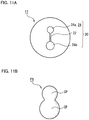
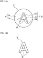
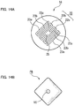
- FIG. 11A to FIG. 14A are schematic bottom views of foam dispenser attachments 11 to 14 according to a first modified example to a fourth modified example.
- FIG. 11B to FIG. 14B are plan views of the foam objects FB respectively dispensed through foam dispenser attachments 11 to 14 of the first modified example to the fourth modified example.
- the foam dispenser attachments 11, 12 of the first modified example and the second modified example are same as the foam dispenser attachment 10 of the first embodiment (see FIG. 10 ) in that each of their outlets 20 has the linear narrowly-opened part 22, and the widely-opened part 24 that is formed contiguously with the narrowly-opened part 22 and is made wider than the narrowly-opened part 22. It is same as the foam dispenser attachment 10 of the first embodiment also in that each of their widely-opened parts 24 is near circular with the diameter larger than the width of the narrowly-opened part 22.
- the first modified example is different from the first embodiment in the aspects below. That is, as illustrated in FIG. 11B , at least a part of the intended shape of the foam object FB, built up after dispensed through the foam dispenser attachment 11 of the first modified example, is shaped such that a plurality of near circular portions CP are overlapped in a plan view.
- the outlet 20 of the first modified example has a plurality of near-circular, widely-opened parts 24 (24a, 24b) that are shrunk from the pluarlity of near-circular portions CP in the intended shape, and the linear narrowly-opened part 22 that connects these widely-opened parts 24 (24a, 24b).
- the widely-opened parts 24 are portions less likely to be clogged even if the liquid agent L should solidify.
- the foam B can still be dispensed through both sides of the clogged portion, so that the solidified component can be kept in contact with the foam B (liquid agent L).
- the solidified component can be softened or dissolved, entrained by the dispensed foam B, and dispensed through the narrowly-opened part 22. Clogging is thus avoidable.
- the foam object FB built up after dispensed through the foam dispenser attachment 11 of the first modified example looks snowman in a plan view.
- the foam object FB may be shaped such that three or more near-circular portions CP are overlapped.
- the outlet 20 is preferably composed of three or more near-circular, widely-opened parts 24, and the linear narrowly-opened parts 22 that mutually connect them.
- outlets 20 of the second modified example and the third modified example illustrated in FIG. 12A and FIG. 13A are same as the first embodiment in that they have a plurality of linear narrowly-opened parts 22 (22a to 22c) that cross each other, but different from the foam dispenser attachment 10 of the first embodiment in that one narrowly-opened part 22a branches into, or crossed with, other narrowly-opened part 22b.
- the foam object FB built up after dispensed through the foam dispenser attachment 12 of the second modified example looks like human in a plan view.
- the foam object FB built up after dispensed through the foam dispenser attachment 13 of the third modified example looks like a letter (letter "A" in this modified example) in a plan view.
- Any one of the narrowly-opened parts 22a to 22c (the narrowly-opened part 22b in this modified example) is divided into a plurality of sections, leaving a separation region 25 in between.
- an inner region 31a surrounded by the narrowly-opened parts 22a to 22c, and an outer region 31b around the narrowly-opened parts 22a to 22c are bridged together by the separation region 25.
- the foam dispenser attachment 13 may therefore be molded easily, and the outlet 20 is suppressed from being deformed contingently due to relative displacement of the inner region 31a and the outer region 31b under dispensing pressure of the foam B.
- the separation region 25 may be provided to a plurality of points of the narrowly-opened parts 22a to 22c.
- the length of the separation region 25, or the divisional distance of the narrowly-opened part 22b is preferably short as possible, so as to give the intended shape to the foam object FB, and may typically be made narrower than the line width of the narrowly-opened part 22b.
- the inner region 31a and the outer region 31b may be joined with a bridge (not illustrated) provided inside the foam dispenser attachment 13. With such design, each of the narrowly-opened parts 22a to 22c may be formed as a contiguous line segment, while disusing the separation region 25.
- the outlet 20 of the fourth modified example illustrated in FIG. 14A is different from the foam dispenser attachment 10 of the first embodiment, in that it has a series of bent or meandering linear narrowly-opened parts 22a, 22b.
- Each of the narrowly-opened parts 22a, 22b has a plurality of line segments 23a to 23c laid in parallel to each other.
- the line segments 23a to 23c are placed in proximity, and the intervals are determined so that the foamy liquid agent (foam B) dispensed through the outlet 20 can swell in the width direction, and then can be crowded to each other to give a planar shape.
- FIG. 14B at least a part of the intended shape of the foam object FB built up after dispensed through the foam dispenser attachment 14 has a planar shape in a plan view.
- the narrowly-opened parts 22a, 22b are partial outlets, and jointly constitute the outlet 20.
- the narrowly-opened parts 22a, 22b of the fourth modified example meander like comb teeth, and the end portions are spaced from each other.
- the foam dispenser attachment 14 has the separation region 25 between the narrowly-opened parts 22a, 22b as the partial outlets.
- the foam B is not dispensed from the separation region 25, so that the foam object FB will have a vacant portion VC.
- the foam dispenser attachment 14 of the fourth modified example builds up the planar intended shape, by gathering the foam B respectively dispensed through the line segments 23a to 23c.
- the intended shape of the foam object FB is planar, it is recommendable to virtually divide the plane into a pluarlity of regions, and to allocate the contiguous partial outlets of the outlet 20, each of which being narrowed from each region.
- the foam object FB having a large area or a complicated shape may accurately be built up with the foam B.
- the outlet 20 used in this invention may have a variety of opening geometries.
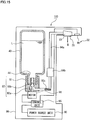
- FIG. 15 is an explanatory drawing illustarting a structure of the foam dispensing container 110 of a second embodiment.
- the foam dispensing container 110 of the second embodiment is different from the the foam dispensing container 100 of the first embodiment (see FIG. 1 ), in that it dispenses the foam B while being elctrically actuated.
- the foam dispensing container 110 of this embodiment has a power source unit 90, a pump mechanism 92 that is powered by the power source unit 90 and delivers the liquid agent L from the container body 40, and a control unit 95 that controls operation of the pump mechanism 92.
- the dispensing operation part of the second embodiment includes a sensing part 96 that senses approach or input operation of the user.
- the control unit 95 activates a motor 98 and the pump mechanism 92 upon detecting the approach or input operation of the user by the sensing part 96, and makes them dispense the predetermined amount of foamy liquid agent (foam B) through the outlet 20.
- the foam dispensing container 110 of the second embodiment is different from the foam dispenser attachment 10 of the first embodiment (see FIG. 1 ), in that the foam dispenser attachment 10 is attached to an enclosure 99 permanently, rather than detachably. According to the foam dispensing container 110 of the second embodiment, the foam dispenser attachment 10 is disposed inside the enclosure 99, with the outlet 20 exposed from the enclosure 99.
- the pump mechanism 92 has a reservoir 91, a piston 93a, a plunger 93b and a check valve 93c.
- the container body 40 with the liquid agent L reserved therein is set upside down in the enclosure 99 while directing the bottleneck downward.
- the reservoir 91 accepts the liquid agent L from the container body 40.
- the piston 93a is actuated by the motor 98, and reciprocally drives the plunger 93b to close the flow channel of the reservoir 91 in a freely openable/closable manner.
- the check valve 93c allows the liquid agent L to flow unidirectionally from the reservoir 91 towards the foam dispenser attachment 10, while preventing backflow.
- the motor 98 is powered by the power source unit 90, and the operation thereof is controlled by the control unit 95.
- a dry cell is typically used.
- the sensing part 96 is a proximity sensor that is disposed near the outlet 20 of the foam dispenser attachment 10, and detects approach of the user's hand.
- the sensing part 96 is typically a reflective sensor having an infrared transceiver. When the sensing part 96 detects approach of the user's hand, a detection signal is sent to the control unit 95 and used for activating the motor 98.
- an air-liquid contact portion 94b In the middle of a tube path 94a that constitutes the flow channel of liquid agent L, connecting the reservoir 91 and the foam dispenser attachment 10, there is provided an air-liquid contact portion 94b.
- the piston 93a When the piston 93a is positioned at the top dead center as illustrated in FIG. 15 , the inlet of the reservoir 91 is closed with the plunger 93b to inhibit traffic of the liquid agent L between the container body 40 and the reservoir 91.
- the motor 98 rotates a cam (not illustrated) to reciprocate the piston 93a.
- the piston 93a descends, the inlet of the reservoir 91 is released, the liquid agent L enters the reservoir 91, and the plunger 93b pushes the liquid agent L towards the foam dispenser attachment 10.
- the pushed liquid agent L is transformed into foam in the air-liquid contact portion 94b, delivered to the foam dispenser attachment 10, and dispensed through the outlet 20 to build up the foam object FB with intended shape (see FIG. 3 ).
- the control unit 95 Upon receiving a detection signal from the sensing part 96, the control unit 95 activate the motor 98 so as to reciprocate the piston 93a a preset number of times. In this way, a predetermined amount of liquid agent L is dispensed as the foam B through the outlet 20.
- the foam dispenser attachment 10 may be used while attached to the enclosure 99.
- the foam dispenser attachment 10 may be used while detachably attached to the pump head part 32.
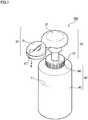
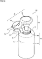
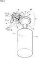
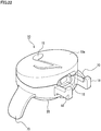
- FIG. 16 is a top perspective view of the foam dispensing container 100 according to the invention
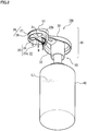
- FIG. 17 is a bottom perspective view of the foam dispensing container 100
- FIG. 18A is a plan view of the foam object FB dispensed through the foam dispensing container 100 of this embodiment
- FIG. 18B is a front elevation of the foam object FB
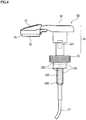
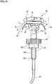
- FIG. 19 is a front elevation of the foam delivery mechanism 50 including the head part 30.
- the foam dispensing container 100 of the third embodiment is different from the first embodiment in that it has an extension part 70, leaving the other aspects in common.
- the foam dispensing container 100 of the third embodiment has the container body 40 that reserves the liquid agent L; and the head part 30 that has the outlet 20, and dispenses the liquid agent L delivered from the container body 40 through the outlet 20 into foam.
- the head part 30 has the dispensing operation part (pump head part 32).
- the dispensing operation part (pump head part 32) dispenses a predetermined amount of foamy liquid agent (foam B) through the outlet 20, each time the user's operation is accepted.
- the dispensed foam B is schematically illustrated in FIG. 16 and FIG. 17 with a two dot chain line.
- foam B The foamy liquid agent (foam B) dispensed through the outlet 20 in the predetermined dispensing direction DD, after one-time or plural times of operations made on the dispensing operation part (pump head part 32), is built up into the desired foam object FB with intended shape as illustrated in FIG. 18A .
- the head part 30 of this embodiment has extension parts 70 that extend beyond the front end position of the outlet 20 with respect to the dispensing direction DD.
- the extension parts 70 may be brought into contact with the dispensing target plane TP, while opposing the outlet 20 to the dispensing target plane TP leaving a space in between. In this way, the distance SP (see FIG. 21 ) bewteen the outlet 20 and the dispensing target plane TP may be kept at a disired level. More specifically, the extension parts 70, when used by bringing the tips (lower ends) into contact with the dispensing target plane TP, can serve as a spacer between the outlet 20 and the dispensing target plane TP.
- the extension part 70 may be used as the shaping member.
- the extension part 70 intended to be used as the shaping member, may be used in contact with the dispensing target plane TP, or may be used while slightly lifted up above the dispensing target plane TP.
- the phrase stating that "the dispensed foamy liquid agent (foam B) is built up into the foam object FB with intended shape” means that the foam B dispensed through the outlet 20 is made up into the predetermined shape on the dispensing target plane TP.
- the intended shape of the foam object FB is not specifically limited, and is exemplified by geometrical shapes, characters' shapes and so forth.
- the intended shape means at least one of plan view geometry of the foam object FB when seen confronting to the dispensing target plane TP, or a three dimensional steric shape of the foam object FB.
- the foam object FB with intended shape includes foam objects shaped differently from those dispensed through a single nozzle with a circular cross section having widely been used in public in the foam dispensing container.
- foam objects include those built up after dispensed through a plurality of outlets, and those built up after dispensed through one or plural outlets that are formed by combining circle, rectangle and so forth.
- This embodiment exemplifies a foam pump bottle designed to mechanically dispense the liquid agent L from the container body 40, when the pump head part 32 is pressed down.
- the piston 55 (see FIG. 19 ) is driven as described later upon press-down operation made on the pump head part 32, and the liquid agent L having been reserved under normal pressure in the container body 40 is sucked up through the suction tube 57.
- a seventh embodiment described later exemplifies an electrically driven dispenser that is electrically actuated to dispense the liquid agent L (see FIG. 28 ).
- the foam dispensing container 100 is composed of the container body 40 that reserves the liquid agent L, and the foam delivery mechanism 50 that is attached to the container body 40 to dispense the liquid agent L.
- the head part 30 of this embodiment is configured by detachably combining the pump head part 32 having the nozzle part 52, and the foam dispenser attachment 10 having the outlet 20 (see FIG. 21 ).
- the head part 30 may be configured by the outlet 20 and the pump head part 32 that are formed in an integrated manner. With such design, the outlet 20 is prevented from wobbling, and thereby the distance SP between the outlet 20 and the dispensing target plane TP (see FIG. 21 ), when the pump head part 32 is pressed down with the extension parts 70 kept pressed against the dispensing target plane TP, is prevented from varying contingently.
- the outlet 20 is formed so as to be opened downward in a bottom face 31 of the head part 30, at a position (on the distal side) laterally projected out from the bottleneck 44 of the container body 40.
- the dispensing direction DD of the foam B dispensed through the outlet 20 of this embodiment is downward, so that a downward view will now be referred to as a plan view.
- the foam B dispensed through the outlet 20 and exposed to the air descends towards the dispensing target plane TP (see FIGs. 18 , 21 ), while being modeled after the outlet 20 as a whole, but locally swells in the individual portions to build up the foam object FB.
- the foam object FB may be built on the dispensing target plane TP after fallen from the outlet 20 and downwardly away from the outlet 20, or may be built so as to fill the space between the outlet 20 and the dispensing target plane TP.
- the level of height of the top face of the foam object FB is preferably equal to or higher than the outlet 20, and lower than the bottom face 31 of the head part 30, from the viewpoint of stably building up the foam object FB into the desired intended shape.
- the dispensing target plane TP is a flat plane or a curved plane on which the foam object FB is built up. Although a user's palm is exemplified in FIG. 18A , this is also exemplified by surfaces of various application tools such as sponge, brush and so forth. For pointed bristles of brush, a flat plane or curved plane given by a set of pointed bristles will be referred to as the dispensing target plane TP.
- the dispensing direction DD of the foam B means an overall direction of the foam B dispensed through the outlet 20.
- the dispensing direction DD is determined by various factors .
- the factors include flow direction of the foam B that passes through the outlet 20, an angle formed between the flow direction and the direction the outlet 20 opens, an angle between the direction of gravity and the direction the outlet 20 opens, and rate of swelling of the foam B that swells after dispensed through the outlet 20 and exposed to the air.
- the head part 30 has the extension parts 70 that extend beyond the front end position of the outlet 20 with respect to the dispensing direction DD.
- the "front end position of the outlet 20 with respect to the dispensing direction DD" means the frontmost position, in the dispensing direction DD, of the circumferential wall (inner circumferential face of the dispensing guide 26) that partitions the outlet 20.
- the inner circumferential face of the dispensing guide 26 is the wall with which the foam B dispensed through the outlet 20 comes into contact.
- the normal line of the outlet 20 of this embodiment (downward in FIG. 19 ) agrees with the dispensing direction DD, and the front end position of the outlet 20 with respect to the dispensing direction DD is kept at constant over the entire portion of the outlet 20.
- the normal line of the outlet 20 and the dispensing direction DD can agree also for the case where both of them are directed obliquely downward or laterally, besides the case of this embodiment where both are directed downward.
- the front end position of the outlet 20 in the dispensing direction DD is given by the frontmost point, in the dispensing direction DD, of the circumferential wall that partitions the outlet 20.
- the cases where the normal line of the outlet 20 crosses the dispensing direction DD include, for example, the case where the outlet 20 was formed by beveling the tip of the tubular dispensing guide 26 (see FIG. 19 ) like an injection needle, or the case where the outlet 20 is formed to have curved face.
- extension parts 70 extend beyond the front end position of the outlet 20 with respect to the dispensing direction DD.
- the extension parts 70 of this embodiment are formed so as to extend, relative to the outlet 20, from the rear side to the front side in the dispensing direction DD. At least the front ends 74 of the extension parts 70 are positioned below the outlet 20, and in other words, positioned ahead in the dispensing direction DD beyond the front end position of the outlet 20.
- the extension parts 70 in this embodiment are fixed in terms of positional relation relative to the outlet 20. With such design, the extension parts 70 are prevented from moving relative to the outlet 20 even when pressed against the dispensing target plane TP, and can keep the distance SP (see FIG. 21 ) between the outlet 20 and the dispensing target plane TP at a desired level.
- the extension parts 70 in this embodiment are arranged outside the inner circumferential face of the dispensing guide 26, so that the foam B dispensed through the outlet 20 falls down on the dispensing target plane TP without making contact with the extension parts 70.
- the extension parts 70 may be formed integrally with the outer circumferential face of the dispensing guide 26, or may be formed separately from the dispensing guide 26.
- the extension parts 70 in this embodiment are formed separately from the dispensing guide 26, outside in the width direction of the dispensing guide 26 and away therefrom.
- the outlet 20 is formed so as to be opened at the bottom end of the dispensing guide 26 provided to the lower portion of the head part 30 (more specifically, the reservoir 60: see FIG. 21 ) .
- the dispensing guide 26 is provided so as to suspend down from the bottom face 31 of the head part 30, and so as to surround the circumference of the outlet 20 like a wall. This prevents the foam B from adhering to the undersurface of the head part 30, making the foam B more releasable, and making it possible to build up a finely-profiled foam object FB.
- this invention is not limited thereto, wherein the dispensing guide 26 may be buried in the wall of the bottom face 31 of the head part 30.
- the bottom face 31 may be made thick, and a through-hole formed so as to extend through the bottom face 31 may be used as the dispensing guide 26.
- the normal line of the outlet 20 (opening) lies parallel to the direction the dispensing guide 26 suspends down.
- the dispensing direction DD in the foam dispensing container 100 of this embodiment therefore lies in the direction of normal line of the outlet 20 (opening), which directs downward as indicated by an arrow in FIG. 17 .
- the extension parts 70 in this embodiment are provided outside the region where the foamy liquid agent (foam B) dispensed through the outlet 20 passes.
- footing regions FP of the palm, as the dispensing target plane TP, where the front ends 74 of the extension parts 70 are brought into contact are indicated by two dot chain lines.
- the footing regions FP are located outside the building region of the foam object FB, and the extension parts 70 are located outside the building region of the foam object FB with intended shape.
- the "front ends 74 of the extension parts 70" mean the lower end faces of the extension parts 70.
- extension parts 70 By making the extension parts 70 flattened on the front ends 74 thereof, the extension parts 70 may be brought into contact stably with the dispensing target plane TP.
- the front ends 74 of the extension parts 70 may however be given curved faces that are slightly rounded, in consideration of gentle touch on the user's palm.
- the front ends 74 of the extension parts 70 are formed within a region that may be encompassed within the palm of one hand of the user (at least adult male) . Positions of the base portions and front ends of the extension parts 70 may be determined depending on geometry or size of the outlet 20.
- the extension parts 70 are prefearbly provided at a plurality of discrete positions around the outlet 20. More preferably, a pair of extension parts 70 are opposingly formed on both sides of the outlet 20, and so as to project out from the circumferential face of the foam dispenser attachment 10.
- the extension parts 70 of this embodiment are intregrally formed with the foam dispenser attachment 10 using a single material. With this design, the extension parts 70 will not be detached from the foam dispenser attachment 10, even when the extension parts 70 are kept pressed against the dispensing target plane TP and applied with drag from the target plane TP as a result of press-down operation made on the pump head part 32.
- the extension parts 70 may be detachably attached to the foam dispenser attachment 10.
- the extension parts 70 may have a detachable engagement part adapted to the foam dispenser attachment 10.
- the detachable engagement part is exemplified by a claw part that grasps the foam dispenser attachment 10, and an adhesive tape used for adhesive fixation to the foam dispenser attachment 10.
- extension parts 70 made detachable from the head part 30, whether the foam dispenser attachment 10 should have a function of spacer or shaping member attributable to the extension parts 70, or not, is now a matter of choice.
- the existing foam dispenser attachment will have a function of spacer or shapoing member, by attaching the extension parts 70 as add-ons.
- the extension parts 70 are formed so as to diverge as they depart from the outlet 20 with respect to the dispensing direction DD (downward in this drawing).
- the pair of extension parts 70 of this embodiment are preferably formed so as to project out from the circumferential face of the foam dispenser attachment 10, and to suspend down diagonally while being curved. More preferably, bottom end parts 72 of the extension parts 70 rise more steeply than top end parts 71. In other words, the pair of extension parts 70 are formed so as to abruptly expand the opposing distance between the top end parts 71, and so as to rise almost normally to the horizontal plane (dispensing target plane TP: see FIG. 21 ) at the bottom end parts 72.
- the foam B is prevented from contacting with, and adhering to the top end parts 71, even if the foam B dispensed through the outlet 20, upon being exposed to the air, should swell right under the outlet 20.
- the foam object FB when built up on the dispensing target plane TP, is also prevented from contacting with the bottom end parts 72.
- the foam object FB can therefore be formed into the desired intended shape in a stable manner.
- the front ends of the extension part 70 of the this embodiment when viewed from the front of the dispensing direction DD confronting to the outlet 20, reside outside the closed area that surrounds the outlet 20, and the position thereof is not specifically limited.
- the pair of extension parts 70 of this embodiment are formed outside the outlet 20, and on both sides thereof away from each other in the width direction (the lateral direction in FIG. 19 ) that crosses the distal-proximal direction connecting the container body 40 and the outlet 20.
- An intermediate part 78 (see FIG. 16 ) that resides between the pair of extension parts 70 and on the distal side (on the front side of the sheet of FIG. 19 ) of the outlet 20 is opened wider than the width of formation W of the outlet 20.
- the dispensing target plane TP (palm) may easily be brought away from the foam dispenser attachment 10 without letting the extension parts 70 contact the thus built foam object FB. More specifically, it is recommendable to elevate the pressed-down foam dispenser attachment 10 from the dispensing target plane TP so as to take the extension parts 70 away from the dispensing target plane TP, and then to take out the foam object FB from under the foam dispenser attachment 10 throuth or just under the intermediate part 78 where the extension parts 70 are not formed.
- the dispensing target plane TP is brought down relative to the foam dispenser attachment 10 to take the extension parts 70 away from the dispensing target plane TP, and then to take out the foam object FB together with the dispensing target plane TP.
- the foam object FB is prevented from being deformed due to contact with the extension parts 70.
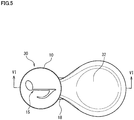
- the outlet 20 of this embodiment has the shape identical to that of the first embodiment, and is composed of an opening that has the contiguous geometry narrowed from the intended shape of the foam object FB.
- the outlet 20 may be composed of a plurality of discretely arranged openings, in the same way as in the foam dispenser attachment 13 described later in a sixth embodiment.
- the linear narrowly-opened part 22 may be a contiguous long opening as described above, or may be composed of discrete openings arranged in line. With intervals of such discreteness adjusted to a predetermined value or below, the foams B dispensed through such plurality of openings arranged in line will be crowded together on the dispensing target plane TP to build up the a contiguous linear foam object FB.
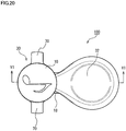
- FIG. 20 is a plan view of the head part 30.
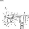
- FIG. 21 is a cross-sectional view taken along line VI-VI in FIG. 20 , and is a sectional side elevation of the head part 30.
- FIG. 22 is a perspective view of the foam dispenser attachment 10.
- FIG. 23A is a top perspective view of the upper half 10a of the foam dispenser attachment 10
- FIG. 23B is a top perspective view of the lower half 10b.
- the head part 30 of this embodiment is configured by combining the nozzle part 52 (see FIG. 21 ) and the foam dispenser attachment 10.
- the foam dispenser attachment 10 accepts the foamy liquid agent (foam B) dispensed through the nozzle opening 54, and dispenses it through the outlet 20 in the predetermined dispensing direction DD, to thereby build up the foam object FB with intended shape.
- the foam dispenser attachment 10 of this embodiment has the above-descirbed extension parts 70 that extend beyond the front end postion of the outlet 20 with respect to the dispensing direction DD.
- the foam dispenser attachment 10 has the fitting part 16 to which the nozzle opening 54 (see FIG. 22 ) is inserted, and the engagement part 18 that detachably engages with the nozzle part 52 (see FIG. 21 ) .
- the pump head part 32 of this embodiment has an umbrella-like shape, and the circumference 33 of the pump head part 32 suspends downward.
- the engagement part 18 of the foam dispenser attachment 10 engages with the circumference 33 of the pump head part 32 particularly on both sides of the nozzle part 52.
- the foam dispenser attachment 10 attached to the pump head part 32 is prevented from inclining back and forth, or left and right relative to the pump head part 32.
- the foam dispenser attachment 10 will therefore not incline or come off contingently, even when the pump head part 32 was pressed down while keeping the front ends 74 of the extension parts 70 pressed against the dispensing target plane TP.
- the present method relates to a method by which the foam B is dispensed from the foam dispensing container 100 (see FIG. 17 ) to build up the foam object FB (see FIG. 18A and FIG. 18B ).
- the foam object FB is built on the dispensing target plane TP.
- the foam dispensing container 100 is a foam pump bottle, and has, as described above, the container body 40 that reserves the liquid agent L, and the head part 30 that dispenses the liquid agent L delivered from the container body 40 through the outlet 20 into foam by predetermined portions, each time the user's press-down operation is accepted.
- the head part 30 has the pump head part 32 that accepts the user's press-down operation.
- the present method includes an arrangement step and a dispensing step.
- the dispensing target plane TP is opposed to the outlet while keeping a predeterined distance SP in between.
- the foamy liquid agent (foam B) is dispensed through the outlet 20 onto the dispensing target plane TP so as to build up a foam object FB with intended shape, by pressing down the head part 30 and by concurrently lowering the dispensing target plane TP while keeping the predetermined distance SP in between.
- the foam B dispensed through the outlet 20 has a small shape retention, and may swell upon being exposed to the air, or can be rounded up into ball shape.
- the shape of the resultant foam object FB can therefore easily vary, just by changing the distance between the outlet 20 and the dispensing target plane TP such as user's palm.
- the foam dispensing container 100, the foam dispenser attachment 10, and the method of producing a foam object of this embodiment the foam object FB that is built up on the dispensing target plane TP upon each dispensing operation made by the user will enjoy an improved reroducibility of shape.
- the foam object FB may be built up into the desired intended shape in a highly accurate manner.
- the present method may also perform a elevation step in which the pressed-down head part 30 and the lowered dispensing target plane TP are elevated while keeping the distance SP in between, and a dispensing step again. Since the distance between the dispensing target plane TP and the outlet 20 is kept constant over the elevation step and the plural times of dispensing steps, so that the desired foam object FB with intended shape may be built up with the foams B dispensed in the plural times of dispensing steps in a highly reproducible manner. At least the arragement step of the present method is preferably carried out while mutually joining the head part 30 and the dispensing target plane TP (see FIG. 21 ).
- the head part 30 and the dispensing target plane TP are joined to each other.
- the head part 30 and the dispensing target plane TP may easily be brought down in an interlocked manner, so that the distance SP between the outlet 20 and the dispensing target plane TP may be kept constant easily.
- the head part 30 has the extension parts 70 that extend beyond the front end position of the outlet 20, with respect to the dispensing direction DD the foamy liquid agent (foam B) is dispensed through the outlet 20.
- the outlet 20 and the dispensing target plane TP are kept at a predetermined distance SP (see FIG. 21 ). In this way, the distance SP may be kept stably during the press-down operation made on the head part 30.
- the front ends 74 of the extension parts 70 may be brought into contact with the surface of the dispensing target plane TP as in the present method.
- the dispensing target plane TP may be held by the extension parts 70, or still alternatively, the extension parts 70 and the dispensing target plane TP may be detachably engaged.
- the user in the arrangement step and the dispensing step, to bring his or her fingers of one palm, which is the dispensing target plane TP, into contact with the head part 30, typically in such a way that he or she bends its fingers of one palm upward to hold the head part 30.
- the head part 30 and the dispensing target plane TP are linked by aid of the fingers in the arrangement step and the dispensing step, and thereby the outlet 20 and the palm (dispensing target plane TP) may be kept at the predetermined distance SP.
- the foam dispenser attachment 11 of the fourth embodiment is in common with the foam dispenser attachment 10 of the third embodiment in that the extension part 70 is provided outside the region where the liquid agent (foam B) passes through, and the region where the foam object FB with intended shape (see FIG. 18A and FIG. 18B ) is built up.
- the fourth embodiment and the third embodiment are same also in that the extention part 70 is formed so as to diverge as it departs from the outlet 20 in the dispensing direction DD.
- the extension part 70 of this embodiment has a form of partially-sphered cylinder (that is, "dome"), with the top and bottom ends opened.
- the foam dispenser attachment 11 of this embodiment is same as the foam dispenser attachment 10 of the third embodiment (see FIG. 19 ) in that, as illustrated in FIG. 24B , the bottom end part 72 of the extension part 70 rises more steeply than the top end part 71.
- the aperture of the opening of the top end part 71 of the extension part 70 can totally contain the dispensing guide 26 both in terms of geometry and size, leaving a void V formed between the whole circumference of the dispensing guide 26 and the extension part 70.
- the aperture of the bottom end part 72 of the extension part 70 can totally contain the intended shape of the foam object FB to be built up (see FIG. 18A and FIG. 18B ), and is larger than the intended shape.
- extension part 70 With the extension part 70 circumferentially formed as in the fourth embodiment, contact between the dispensing target plane TP (see FIG. 18A and FIG. 18B ) and the extension part 70 is stabilized, and thereby the dispensing target plane TP can be confronted accurately to the outlet 20 without being inclined.
- Geometry of the circumferential go-around-type extension part 70 is not specifically limited. Although in this embodiment it is given as the partially spherical shape that diverges downward, the shape is not limited thereto .
- the extension part 70 may have a form of truncated cone, or may have a shape widened or thickened from the geometry of aperture of the outlet 20, or from the dispensing guide 26.
- the bottom end of the extension part 70 may be circular as shown in this embodiment, or may alternatively have a shape other than circule, such as a rectangular shape, and may have a shape thickened from the geometry of aperture of the outlet 20.
- the go-around-type extension part 70 may be made translucent or semi-translucent, entirely or partially. Still alternatively, the extension part 70 may have a peephole provided to a part thereof, or may have a notch at the bottom end thereof. With such design, how the foam object FB was built up may be visually confirmed, before the foam object FB built on the dispensing target plane TP is taken out from the extension part 70.
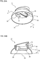
- FIG. 25A is a bottom perspective view of a foam dispenser attachment 12 according to a fifth embodiment.
- FIG. 25B is a side elevation of the foam dispenser attachment 12, and
- FIG. 25 is a bottom view.
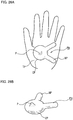
- FIG. 26A is a plan view of the foam object FB dispensed through the foam dispenser attachment 12 of the fifth embodiment, and
- FIG. 26B is a perspective view of the foam object FB.
- the foam dispenser attachment 12 of the fifth embodiment is different from the foam dispenser attachment 10 of the third embodiment in that at least the front end part 74 of the extension part 70 is provided within the area where the foam object FB with intended shape is built.
- the extension part 70 of this embodiment is preferably brought into contact with the foam B dispensed through the outlet 20.
- the extension part 70 of the fifth embodiment is provided, as illustrated in FIG. 25C , inside the outlet 20 in a plan view in the dispensing direction DD. A part of the foam B dispensed through the outlet 20 therefore streams on the surface of the extension part 70 down onto the dispensing target plane TP.
- extension part 70 when the extension part 70 is drawn out from the built foam object FB, a part of the foam B is dragged up by the extension part 70 while adhereing thereto, to produce a pointed part P on the surface of the foam object FB. Accordingly, for an exemplary case as illustrated in FIGs. 26A and 26B where the foam object FB is built up into a shape of animal (rabbit) or other characters, it is now possible to make a projection that represents a nose or so on the foam object FB.
- the extension part 70 may be used as a shaping member for creating a three-dimensional portion onto the foam object FB.
- the extension part 70 of this embodiment is formed inside the inner circumferential face of the dispensing guide 26 with which the foam B dispensed through the outlet 20 comes into contact.
- the extension part 70 may be formed integrally with the inner circumferentail face of the dispensing guide 26, or may be formed separately from the dispensing guide 26.
- the extension part 70 of this embodiment is arranged at a position inwardly away from the inner circumferential face of the dispensing guide 26, and separately from the dispensing guide 26.
- the extension part 70 of this embodiment may be used as a spacer for keeping the distance SP between the outlet 20 and the dispensing target plane TP (see FIG. 21 ) to a predetermined value, while bringing the front end part 74 thereof into contact with the dispensing target plane TP. In this way, the extension part 70 of this embodiment can serve both as the shaping member and the spacer.
- the extension part 70 of this embodiment has a pillar form as a whole, and is provided in parallel to the dispensing direction DD, so as to project out from the ceiling 66 of the reservoir 60 of the foam dispenser attachment 10 (see FIG. 21 ).
- the extension part 70 of this embodiment has the front end part 74, and a rod-like stem part 76 with a diameter shrunk from the front end part 74.
- the front end part 74 in this embodiment appears spherical, this invention is not limited thereto.
- the bottom face of the front end part 74 may be formed flat. With such design, the front end part 74 can contact by surface with the dispensing target plane TP, so that the dispensing target plane TP may be confronted stably to the outlet 20.
- the shape of the front end part 74 is not limited to sphere, but may have various shapes depending on the geometry and size of the pointed part P to be formed on the foam object FB.
- the outlet 20 has the linear narrowly-opened part 22, and the widely-opened part 24 that is formed contiguously with the narrowly-opened part 22 and is made wider than the narrowly-opened part 22.
- the foam B dispensed through the widely-opened part 24 composes a near-circular part CP of the foam object FB, and the foam B dispensed through the narrowly-opened part 22 composes a narrow portion NP of the foam object FB.
- the extension part 70 is provided within the widely-opened part 24.
- the stem part 76 of the extension part 70 of this embodiment is vertically arranged nearly at the center of the widely-opened part 24.
- the extension part 70 can therefore come into contact with the foam object FB nearly at the center of the near-circular part CP, so that the near-circular part CP and the narrow portion NP will not be disturbed in their contours, and the foam object FB is suppressed from being deformed as a whole.
- the extension part 70 may be provided inside the widely-opened part 24.
- the pointed part that typically represents eyes, nose or the like may be formed in the foam object FB having various characters' shapes, within a single or a plurality of near-circular parts CP.
- a plurality of extension parts 70 may be provided to the head part 30, and the extension parts 70 may be arranged respectively inside the plurality of widely-opened parts 24.
- the control unit 95 activates the pump mechanism 92 and makes it dispense a predetermined amount of foamy liquid agent L through the outlet 20.
Landscapes
- Health & Medical Sciences (AREA)
- Public Health (AREA)
- Containers And Packaging Bodies Having A Special Means To Remove Contents (AREA)
- Closures For Containers (AREA)
Claims (16)
- Schaumspendebehälter (100, 110), der aufweist: einen Behälterkörper (40), der ein flüssiges Mittel zurückhält; einen Kopfteil (30), der einen Auslass (20) hat und das flüssige Mittel, das von dem Behälterkörper (40) zugeführt wird, durch den Auslass (20) als Schaum abgibt; und einen Spendebedienteil (32), der jedes Mal, wenn er eine Benutzerbedienung annimmt, das Abgeben einer vorgegebenen Menge des schaumigen flüssigen Mittels durch den Auslass (20) ermöglicht,
wobei der Auslass (20) eine Öffnung mit einer zusammenhängenden Geometrie ist, die von einer geplanten Form verengt ist, und ausgebildet ist, um das schaumige flüssige Mittel aufzubauen, das als ein Ergebnis einer einzigen oder mehrerer Bedienungen, die an dem Spendebedienteil (32) vorgenommen werden, in einer Draufsicht in der Abgaberichtung gesehen, in der geplanten Form abgegeben wird,
dadurch gekennzeichnet, dass
der Auslass (20) einen linearen geöffneten Teil hat,
und der Kopfteil (30) einen Erstreckungsteil (70) hat, der sich in Bezug auf die Abgaberichtung über die vordere Endposition des Auslasses (20) hinaus erstreckt, und
das durch den Auslass (20) abgegebene schaumige flüssige Mittel zu einem Schaumobjekt (FB) mit der geplanten Form aufgebaut wird. - Schaumspendebehälter (100, 110) nach Anspruch 1, wobei der Auslass (20) einen eng geöffneten Teil (22, 22a, 22b, 22c) als den linearen geöffneten Teil hat; und einen weit geöffneten Teil (24, 24a, 24b), der mit dem eng geöffneten Teil (22, 22a, 22b, 22c) in Verbindung steht und breiter als der eng geöffnete Teil (22, 22a, 22b, 22c) hergestellt ist.
- Schaumspendebehälter (100, 110) nach Anspruch 2, wobei der weit geöffnete Teil (24, 24a, 24b) nahezu kreisförmig ist mit einem Durchmesser, der größer als eine Breite des eng geöffneten Teils (22, 22a, 22b, 22c) ist.
- Schaumspendebehälter (100, 110) nach einem der Ansprüche 1 bis 3, wobei der Kopfteil (30) einen Vorratsbehälter (60) hat, der das schaumige flüssige Mittel zurückhält, das von dem Behälterkörper (40) zugeführt wird, und wobei der Vorratsbehälter (60) eine Decke (66) hat, die sich in Richtung der vorderen Endseite der Zufuhrrichtung des flüssigen Mittels und zu dem Auslass (20) abwärts neigt.
- Schaumspendebehälter (100, 110) nach Anspruch 4, wobei der Kopfteil (30) einen Düsenteil (52) hat, der das schaumige flüssige Mittel, das von dem Behälterkörper (40) in einer schrägen Abwärtsrichtung in den Vorratsbehälter (60) zugeführt wird, abgibt; und eine geneigte Fläche (62), die in dem Vorratsbehälter (60) bereitgestellt ist, so dass sie der schrägen Abwärtsrichtung nahezu gegenübersteht, und
wobei der Auslass (20) derart ausgebildet ist, dass er sich zwischen der vorderen Endseite und der Basisseite der geneigten Fläche (62) erstreckt. - Schaumspendebehälter (100, 110) nach Anspruch 5, wobei der Auslass (20) einen eng geöffneten Teil (22, 22a, 22b, 22c) als den linearen geöffneten Teil und einen weit geöffneten Teil (24, 24a, 24b), der mit dem eng geöffneten Teil (22, 22a, 22b, 22c) in Verbindung steht und breiter als der eng geöffnete Teil (22, 22a, 22b, 22c) hergestellt ist, hat, und
wobei der weit geöffnete Teil (24, 24a, 24b) auf der vorderen Endseite der geneigten Fläche (62) angeordnet ist und der eng geöffnete Teil (22, 22a, 22b, 22c) auf der Basisseite angeordnet ist. - Schaumspendebehälter (100, 110) nach den Ansprüchen 5 oder 6, wobei der Vorratsbehälter (60) einen Innenboden hat, dessen Höhenniveau auf der vorderen Endseite der geneigten Fläche (62) höher als auf der Basisseite ist.
- Schaumspendebehälter (100, 110) nach einem der Ansprüche 4 bis 7, wobei der Kopfteil (30) ferner eine Spendeführung (26) aufweist, die derart bereitgestellt ist, dass sie sich von dem Vorratsbehälter (60) nach unten erstreckt und den Auslass (20) an dem unteren Ende hat, und
wobei die Spendeführung (26) ein gerades rohrartiges Durchgangsloch hat, das zu einer mit dem Auslass (20) identischen Geometrie ausgebildet ist. - Schaumspendebehälter (100, 110) nach einem der Ansprüche 1 bis 8, wobei der Kopfteil (30) einen Düsenteil (52) mit einer Düsenöffnung (54) hat, durch die das schaumige flüssige Mittel aus dem Behälterkörper (40) zugeführt wird; und einen Schaumspenderaufsatz (10) mit dem Auslass (20), der lösbar an dem Düsenteil (52) befestigt ist, so dass der Auslass (20) und die Düsenöffnung (54) miteinander in Verbindung stehen können, und
wobei der Schaumspenderaufsatz (10) ein Anschlussstück (16) hat, in das die Düsenöffnung (54) eingesetzt ist, und einen Eingreifteil (18), der lösbar mit dem Düsenteil (52) eingreift. - Schaumspendebehälter (100, 110) nach Anspruch 9, wobei der Erstreckungsteil (70) außerhalb eines Bereichs bereitgestellt ist, den das durch den Auslass (20) abgegebene schaumige flüssige Mittel durchläuft, und außerhalb eines Bereichs, in dem das Schaumobjekt (FB) mit der geplanten Form aufgebaut wird.
- Schaumspendebehälter (100, 110) nach Anspruch 10, wobei die Erstreckungsteile (70) an mehreren diskreten Positionen um den Auslass (20) herum bereitgestellt sind.
- Schaumspendebehälter (100, 110) nach Anspruch 10, wobei der Erstreckungsteil (70) umlaufend ausgebildet ist, so dass er den Umfang des Auslasses (20) umgibt.
- Schaumspendebehälter (100, 110) nach einem der Ansprüche 10 bis 12, wobei der Erstreckungsteil (70) derart ausgebildet ist, dass er mit größer werdender Entfernung von dem Auslass (20) in der Abgaberichtung divergiert.
- Schaumspendebehälter (100, 110) nach einem der Ansprüche 1 bis 9, wobei der Erstreckungsteil (70) derart bereitgestellt ist, dass wenigstens das vordere Ende in einen Bereich fällt, in dem das Schaumobjekt (FB) mit der geplanten Form aufgebaut wird.
- Schaumspendebehälter (100, 110) nach Anspruch 14, wobei der Erstreckungsteil (70) in einer Draufsicht in der Abgaberichtung gesehen im Inneren des Auslasses (20) bereitgestellt ist.
- Schaumspendebehälter (100, 110) nach Anspruch 14 oder 15, wobei der Erstreckungsteil (70) ein vorderes Ende und einen stabartigen Stielteil (76), der dünner als das vordere Ende ausgebildet ist, hat.
Applications Claiming Priority (4)
| Application Number | Priority Date | Filing Date | Title |
|---|---|---|---|
| JP2014241538 | 2014-11-28 | ||
| JP2015115150A JP6242368B2 (ja) | 2015-06-05 | 2015-06-05 | 泡吐出容器 |
| JP2015130405A JP6215263B2 (ja) | 2014-11-28 | 2015-06-29 | 泡吐出容器 |
| PCT/JP2015/083474 WO2016084955A1 (ja) | 2014-11-28 | 2015-11-27 | 泡吐出容器 |
Publications (3)
| Publication Number | Publication Date |
|---|---|
| EP3225564A1 EP3225564A1 (de) | 2017-10-04 |
| EP3225564A4 EP3225564A4 (de) | 2018-10-17 |
| EP3225564B1 true EP3225564B1 (de) | 2020-05-06 |
Family
ID=59422557
Family Applications (1)
| Application Number | Title | Priority Date | Filing Date |
|---|---|---|---|
| EP15863617.5A Active EP3225564B1 (de) | 2014-11-28 | 2015-11-27 | Schaumspendebehälter |
Country Status (3)
| Country | Link |
|---|---|
| US (2) | US10478834B2 (de) |
| EP (1) | EP3225564B1 (de) |
| CN (1) | CN107000906B (de) |
Families Citing this family (12)
| Publication number | Priority date | Publication date | Assignee | Title |
|---|---|---|---|---|
| US11564537B2 (en) * | 2013-01-20 | 2023-01-31 | Gemtera Inc. | Ubiquitous, embedded surface-cleansing devices |
| US10478834B2 (en) * | 2014-11-28 | 2019-11-19 | Kao Corporation | Foam dispensing container |
| US10349785B2 (en) | 2015-04-28 | 2019-07-16 | Kao Corporation | Foam discharge device |
| CN109091047B (zh) * | 2018-07-19 | 2023-05-16 | 北京小米移动软件有限公司 | 洗手机的出液控制方法、装置和存储介质 |
| JP1635837S (de) * | 2019-01-31 | 2019-07-08 | ||
| USD940824S1 (en) * | 2020-01-17 | 2022-01-11 | Jen Sian Industrial Co., Ltd. | Refillable pressure sprayer |
| CN111938478A (zh) * | 2020-07-12 | 2020-11-17 | 意杉(杭州)科技有限公司 | 一种洗手给皂器 |
| CN111789512A (zh) * | 2020-08-12 | 2020-10-20 | 广东工业大学 | 一种洗手机 |
| US12484597B2 (en) * | 2022-04-12 | 2025-12-02 | Bcc Product Development, L.L.C. | System and method for dispensing a substance into one of multiple patterns |
| USD1037863S1 (en) * | 2022-08-08 | 2024-08-06 | Xiaoning Liang | Soap dispenser |
| CN115489879A (zh) * | 2022-10-25 | 2022-12-20 | 上海吉刻贸易有限公司 | 一种奶油喷射装置 |
| NL2036508B1 (nl) * | 2023-12-13 | 2025-06-20 | Medspray B V | Beeldweergave-inrichting en verstuiverinrichting |
Family Cites Families (57)
| Publication number | Priority date | Publication date | Assignee | Title |
|---|---|---|---|---|
| US1740384A (en) * | 1928-06-22 | 1929-12-17 | Newt E Wright | Milk-can cover and support |
| CH186697A (de) | 1935-09-30 | 1936-09-30 | Benteli Berta | Tube für pastenartige Substanzen. |
| US2779514A (en) | 1955-06-30 | 1957-01-29 | Arthur P Kebel | Dispensing apparatus |
| US3092334A (en) * | 1961-09-19 | 1963-06-04 | Peterson Dana | Shower attachment |
| US3572591A (en) * | 1969-02-24 | 1971-03-30 | Precision Valve Corp | Aerosol powder marking device |
| US3842633A (en) | 1973-12-14 | 1974-10-22 | Hartford Special Machinery Co | Resiliently biased starter blade supporting arm for thread roller |
| JPS5723009Y2 (de) | 1976-10-04 | 1982-05-19 | ||
| JPS6154248A (ja) * | 1984-08-21 | 1986-03-18 | Toray Ind Inc | 繊維シートの交絡処理方法 |
| DE3615741A1 (de) | 1986-05-09 | 1987-11-12 | Haunschild Virginie | Deko-spruehapplikator und entsprechende anwendung |
| US4865257A (en) * | 1988-07-20 | 1989-09-12 | Bailey Amy L | Spray guard adapted for use with a wand for spraying a liquid onto vegetation |
| JPH0480880U (de) | 1990-11-28 | 1992-07-14 | ||
| DE4108646A1 (de) * | 1991-03-16 | 1992-09-17 | Pfeiffer Erich Gmbh & Co Kg | Austragvorrichtung fuer medien |
| JP2587089Y2 (ja) | 1992-06-22 | 1998-12-14 | ポーラ化成工業株式会社 | 泡受皿 |
| JPH0728056U (ja) | 1993-10-27 | 1995-05-23 | 花王株式会社 | スクイズ容器用弁 |
| FR2744104B1 (fr) | 1996-01-29 | 1998-03-20 | Oreal | Dispositif de conditionnement, de distribution et d'application d'un gel ou mousse |
| JP2000185782A (ja) | 1998-12-21 | 2000-07-04 | Kyowa Industrial Co Ltd | エアゾール製品 |
| US6145756A (en) * | 1999-05-01 | 2000-11-14 | Kohls; Corwin | Gardening applicator for delivering liquid chemicals to selected vegetation |
| US6422778B2 (en) * | 2000-04-03 | 2002-07-23 | 3M Innovative Properties Company | Surgical prep solution applicator system and methods |
| JP3976476B2 (ja) | 2000-05-29 | 2007-09-19 | ライオン株式会社 | 泡吐出容器 |
| US6679438B1 (en) * | 2002-03-13 | 2004-01-20 | Todd Didlo | Guard for spray applicator |
| US20040086321A1 (en) * | 2002-11-01 | 2004-05-06 | Burkholz Jonathan Karl | Aerosol patient preparatory applicator |
| EP1888252A2 (de) * | 2005-05-26 | 2008-02-20 | Incro Limited | Rückschlagventil und ein solches rückschlagventil aufweisende fluidvorrichtung mit geteiltem körper |
| GB0520608D0 (en) * | 2005-10-11 | 2005-11-16 | Incro Ltd | Pump dispenser |
| DE102006012302A1 (de) * | 2006-03-15 | 2007-09-27 | Seaquist Perfect Dispensing Gmbh | Abgabevorrichtung |
| JP4851883B2 (ja) | 2006-08-04 | 2012-01-11 | 花王株式会社 | 泡吐出器 |
| USD610227S1 (en) * | 2006-09-22 | 2010-02-16 | Mark Hunter | Simulative flower attachment for a shower |
| US20080264974A1 (en) * | 2007-03-15 | 2008-10-30 | Soaptronic International, Llc | Liquid dispenser |
| US8056768B2 (en) | 2007-12-28 | 2011-11-15 | Snodgrass David L | Foam pump assembly |
| GB0901907D0 (en) * | 2009-02-05 | 2009-03-11 | Leafgreen Ltd | Manual pump type fluid dispenser |
| JP2010026033A (ja) | 2008-07-16 | 2010-02-04 | Yamaha Motor Co Ltd | 移動体用の発音装置 |
| JP5131698B2 (ja) | 2008-10-30 | 2013-01-30 | 株式会社吉野工業所 | 手動押下げ注出ポンプ用ノズルヘッド |
| JP5412106B2 (ja) * | 2008-12-25 | 2014-02-12 | ライオン株式会社 | 泡吐出用アダプタ及び泡ポンプ付き容器 |
| JP2010269233A (ja) * | 2009-05-20 | 2010-12-02 | Lion Corp | 泡吐出用アダプタ及び泡吐出装置 |
| GB0912065D0 (en) | 2009-07-10 | 2009-08-19 | Reckitt & Colman Overseas | A fluid delivery system |
| EP2505266B1 (de) | 2009-11-25 | 2020-03-18 | Daizo Corporation | Sprühdüse und aerosolprodukt |
| JP3159292U (ja) | 2010-02-25 | 2010-05-13 | 美通興業有限公司 | 泡沫発生装置 |
| JP2011184088A (ja) | 2010-03-10 | 2011-09-22 | Tosei Yoki Kk | ディスペンサーのノズルカバー |
| CN103402650B (zh) * | 2010-03-17 | 2016-07-20 | Ipnip有限公司 | 具有部分分配装置的容器 |
| EP2572795A4 (de) | 2010-05-06 | 2013-10-16 | Mitani Valve Co Ltd | Anbauelement für aufschäumbehälterinhalt und pumpenprodukt und aerosolprodukt, die mit einem anbauelement für aufschäumbehälterinhalte ausgestattet sind |
| US8814007B2 (en) * | 2010-12-31 | 2014-08-26 | Medline Industries, Inc. | Dispenser with directional flow controlling flange and corresponding systems |
| JP5650027B2 (ja) | 2011-03-23 | 2015-01-07 | 株式会社ライフプラテック | 泡ポンプの空気弁構造 |
| US8960507B2 (en) | 2011-10-25 | 2015-02-24 | Rieke Corporation | Pump dispenser with an inclined nozzle |
| US9220377B2 (en) * | 2012-08-02 | 2015-12-29 | Rubbermaid Commercial Products, Llc | Foam dispensing pump with decompression feature |
| JP5936991B2 (ja) | 2012-10-31 | 2016-06-22 | 株式会社吉野工業所 | 噴出ヘッド及び、それを備える容器 |
| CN203209211U (zh) | 2013-03-30 | 2013-09-25 | 常州市美特精密电机有限公司 | 一种多孔实心锥形喷嘴 |
| US9415404B2 (en) * | 2013-06-17 | 2016-08-16 | The Boeing Company | High viscosity fluid dispensing system |
| US10478834B2 (en) * | 2014-11-28 | 2019-11-19 | Kao Corporation | Foam dispensing container |
| US10349785B2 (en) | 2015-04-28 | 2019-07-16 | Kao Corporation | Foam discharge device |
| JP1548679S (de) | 2015-05-29 | 2016-05-09 | ||
| JP1545214S (de) | 2015-05-29 | 2016-03-07 | ||
| JP1545215S (de) | 2015-05-29 | 2016-03-07 | ||
| JP1548678S (de) | 2015-05-29 | 2016-05-09 | ||
| JP6467299B2 (ja) | 2015-06-22 | 2019-02-13 | 花王株式会社 | 泡吐出容器 |
| JP6629533B2 (ja) | 2015-06-29 | 2020-01-15 | 花王株式会社 | 泡吐出ノズル及び泡吐出装置 |
| JP6486222B2 (ja) | 2015-06-29 | 2019-03-20 | 花王株式会社 | ディスペンサー |
| JP6619960B2 (ja) | 2015-06-30 | 2019-12-11 | 花王株式会社 | 泡吐出容器入り液体洗浄剤組成物 |
| JP6985820B2 (ja) | 2017-05-26 | 2021-12-22 | 花王株式会社 | 泡プロジェクションマッピング方法 |
-
2015
- 2015-11-27 US US15/531,288 patent/US10478834B2/en active Active
- 2015-11-27 CN CN201580063581.6A patent/CN107000906B/zh active Active
- 2015-11-27 EP EP15863617.5A patent/EP3225564B1/de active Active
-
2019
- 2019-10-25 US US16/664,301 patent/US11020755B2/en active Active
Non-Patent Citations (1)
| Title |
|---|
| None * |
Also Published As
| Publication number | Publication date |
|---|---|
| EP3225564A1 (de) | 2017-10-04 |
| CN107000906B (zh) | 2019-11-22 |
| US11020755B2 (en) | 2021-06-01 |
| US20200055061A1 (en) | 2020-02-20 |
| CN107000906A (zh) | 2017-08-01 |
| EP3225564A4 (de) | 2018-10-17 |
| US10478834B2 (en) | 2019-11-19 |
| US20180297040A1 (en) | 2018-10-18 |
Similar Documents
| Publication | Publication Date | Title |
|---|---|---|
| US11020755B2 (en) | Foam dispensing container | |
| JP6587662B2 (ja) | 泡吐出容器 | |
| CN114030767B (zh) | 泡沫吐出容器 | |
| EP3315206B1 (de) | Blasenentladedüse und blasenentladevorrichtung | |
| US6860404B2 (en) | Device and method for dispensing a fluid product | |
| EP0461891A2 (de) | Kombination eines Behälters mit einer durch Handdruck betätigten Abgabevorrichtung | |
| EP3290122B1 (de) | Schaumspendevorrichtung | |
| JP6467299B2 (ja) | 泡吐出容器 | |
| US6679439B2 (en) | Device for dispensing a fluid product and method of dispensing a fluid product | |
| CN104582861B (zh) | 用于输送流体组合物的元件、相关分配装置及相关方法 | |
| KR102513028B1 (ko) | 네일 폴리싱을 위한 필름-형성 고분자를 갖는, 브러쉬와 통합된 캡슐 | |
| EP2699483B1 (de) | Spender mit bruchelement | |
| JP2017193374A (ja) | 泡吐出装置 | |
| JP6242368B2 (ja) | 泡吐出容器 | |
| US20190125137A1 (en) | Foam discharge device | |
| WO2016084955A1 (ja) | 泡吐出容器 | |
| JP6486222B2 (ja) | ディスペンサー | |
| TWI736609B (zh) | 泡沫噴出裝置 | |
| EP2863784B1 (de) | Streugut- und schaumspender | |
| JP2018002310A (ja) | 泡吐出容器 | |
| HK1238221B (zh) | 泡沫吐出容器 | |
| HK1238221A1 (en) | Foam dispensing container | |
| JP6622246B2 (ja) | 泡吐出装置 | |
| CN101217990A (zh) | 喷射装置、用于喷射一定量液体的方法及该装置的制造方法 | |
| JP7385797B1 (ja) | 噴霧式目薬容器セット |
Legal Events
| Date | Code | Title | Description |
|---|---|---|---|
| STAA | Information on the status of an ep patent application or granted ep patent |
Free format text: STATUS: THE INTERNATIONAL PUBLICATION HAS BEEN MADE |
|
| PUAI | Public reference made under article 153(3) epc to a published international application that has entered the european phase |
Free format text: ORIGINAL CODE: 0009012 |
|
| STAA | Information on the status of an ep patent application or granted ep patent |
Free format text: STATUS: REQUEST FOR EXAMINATION WAS MADE |
|
| 17P | Request for examination filed |
Effective date: 20170628 |
|
| AK | Designated contracting states |
Kind code of ref document: A1 Designated state(s): AL AT BE BG CH CY CZ DE DK EE ES FI FR GB GR HR HU IE IS IT LI LT LU LV MC MK MT NL NO PL PT RO RS SE SI SK SM TR |
|
| AX | Request for extension of the european patent |
Extension state: BA ME |
|
| DAV | Request for validation of the european patent (deleted) | ||
| DAX | Request for extension of the european patent (deleted) | ||
| A4 | Supplementary search report drawn up and despatched |
Effective date: 20180913 |
|
| RIC1 | Information provided on ipc code assigned before grant |
Ipc: B65D 83/00 20060101ALI20180907BHEP Ipc: A47K 5/12 20060101ALI20180907BHEP Ipc: A47K 5/16 20060101ALI20180907BHEP Ipc: B05B 11/00 20060101ALI20180907BHEP Ipc: B05B 7/00 20060101ALI20180907BHEP Ipc: B05B 1/02 20060101ALI20180907BHEP Ipc: B65D 47/34 20060101AFI20180907BHEP Ipc: A47K 5/14 20060101ALI20180907BHEP |
|
| GRAP | Despatch of communication of intention to grant a patent |
Free format text: ORIGINAL CODE: EPIDOSNIGR1 |
|
| STAA | Information on the status of an ep patent application or granted ep patent |
Free format text: STATUS: GRANT OF PATENT IS INTENDED |
|
| RIC1 | Information provided on ipc code assigned before grant |
Ipc: B05B 1/02 20060101ALI20191031BHEP Ipc: B05B 7/00 20060101ALI20191031BHEP Ipc: A47K 5/14 20060101ALI20191031BHEP Ipc: B05B 11/00 20060101ALI20191031BHEP Ipc: A47K 5/12 20060101ALI20191031BHEP Ipc: B65D 47/34 20060101AFI20191031BHEP Ipc: A47K 5/16 20060101ALI20191031BHEP Ipc: B65D 83/00 20060101ALI20191031BHEP |
|
| INTG | Intention to grant announced |
Effective date: 20191121 |
|
| GRAS | Grant fee paid |
Free format text: ORIGINAL CODE: EPIDOSNIGR3 |
|
| GRAA | (expected) grant |
Free format text: ORIGINAL CODE: 0009210 |
|
| STAA | Information on the status of an ep patent application or granted ep patent |
Free format text: STATUS: THE PATENT HAS BEEN GRANTED |
|
| AK | Designated contracting states |
Kind code of ref document: B1 Designated state(s): AL AT BE BG CH CY CZ DE DK EE ES FI FR GB GR HR HU IE IS IT LI LT LU LV MC MK MT NL NO PL PT RO RS SE SI SK SM TR |
|
| REG | Reference to a national code |
Ref country code: GB Ref legal event code: FG4D |
|
| REG | Reference to a national code |
Ref country code: CH Ref legal event code: EP Ref country code: AT Ref legal event code: REF Ref document number: 1266395 Country of ref document: AT Kind code of ref document: T Effective date: 20200515 |
|
| REG | Reference to a national code |
Ref country code: DE Ref legal event code: R096 Ref document number: 602015052527 Country of ref document: DE |
|
| REG | Reference to a national code |
Ref country code: IE Ref legal event code: FG4D |
|
| REG | Reference to a national code |
Ref country code: LT Ref legal event code: MG4D |
|
| REG | Reference to a national code |
Ref country code: NL Ref legal event code: MP Effective date: 20200506 |
|
| PG25 | Lapsed in a contracting state [announced via postgrant information from national office to epo] |
Ref country code: GR Free format text: LAPSE BECAUSE OF FAILURE TO SUBMIT A TRANSLATION OF THE DESCRIPTION OR TO PAY THE FEE WITHIN THE PRESCRIBED TIME-LIMIT Effective date: 20200807 Ref country code: NO Free format text: LAPSE BECAUSE OF FAILURE TO SUBMIT A TRANSLATION OF THE DESCRIPTION OR TO PAY THE FEE WITHIN THE PRESCRIBED TIME-LIMIT Effective date: 20200806 Ref country code: LT Free format text: LAPSE BECAUSE OF FAILURE TO SUBMIT A TRANSLATION OF THE DESCRIPTION OR TO PAY THE FEE WITHIN THE PRESCRIBED TIME-LIMIT Effective date: 20200506 Ref country code: SE Free format text: LAPSE BECAUSE OF FAILURE TO SUBMIT A TRANSLATION OF THE DESCRIPTION OR TO PAY THE FEE WITHIN THE PRESCRIBED TIME-LIMIT Effective date: 20200506 Ref country code: IS Free format text: LAPSE BECAUSE OF FAILURE TO SUBMIT A TRANSLATION OF THE DESCRIPTION OR TO PAY THE FEE WITHIN THE PRESCRIBED TIME-LIMIT Effective date: 20200906 Ref country code: PT Free format text: LAPSE BECAUSE OF FAILURE TO SUBMIT A TRANSLATION OF THE DESCRIPTION OR TO PAY THE FEE WITHIN THE PRESCRIBED TIME-LIMIT Effective date: 20200907 Ref country code: FI Free format text: LAPSE BECAUSE OF FAILURE TO SUBMIT A TRANSLATION OF THE DESCRIPTION OR TO PAY THE FEE WITHIN THE PRESCRIBED TIME-LIMIT Effective date: 20200506 |
|
| PG25 | Lapsed in a contracting state [announced via postgrant information from national office to epo] |
Ref country code: HR Free format text: LAPSE BECAUSE OF FAILURE TO SUBMIT A TRANSLATION OF THE DESCRIPTION OR TO PAY THE FEE WITHIN THE PRESCRIBED TIME-LIMIT Effective date: 20200506 Ref country code: LV Free format text: LAPSE BECAUSE OF FAILURE TO SUBMIT A TRANSLATION OF THE DESCRIPTION OR TO PAY THE FEE WITHIN THE PRESCRIBED TIME-LIMIT Effective date: 20200506 Ref country code: BG Free format text: LAPSE BECAUSE OF FAILURE TO SUBMIT A TRANSLATION OF THE DESCRIPTION OR TO PAY THE FEE WITHIN THE PRESCRIBED TIME-LIMIT Effective date: 20200806 Ref country code: RS Free format text: LAPSE BECAUSE OF FAILURE TO SUBMIT A TRANSLATION OF THE DESCRIPTION OR TO PAY THE FEE WITHIN THE PRESCRIBED TIME-LIMIT Effective date: 20200506 |
|
| REG | Reference to a national code |
Ref country code: AT Ref legal event code: MK05 Ref document number: 1266395 Country of ref document: AT Kind code of ref document: T Effective date: 20200506 |
|
| PG25 | Lapsed in a contracting state [announced via postgrant information from national office to epo] |
Ref country code: AL Free format text: LAPSE BECAUSE OF FAILURE TO SUBMIT A TRANSLATION OF THE DESCRIPTION OR TO PAY THE FEE WITHIN THE PRESCRIBED TIME-LIMIT Effective date: 20200506 Ref country code: NL Free format text: LAPSE BECAUSE OF FAILURE TO SUBMIT A TRANSLATION OF THE DESCRIPTION OR TO PAY THE FEE WITHIN THE PRESCRIBED TIME-LIMIT Effective date: 20200506 |
|
| PG25 | Lapsed in a contracting state [announced via postgrant information from national office to epo] |
Ref country code: ES Free format text: LAPSE BECAUSE OF FAILURE TO SUBMIT A TRANSLATION OF THE DESCRIPTION OR TO PAY THE FEE WITHIN THE PRESCRIBED TIME-LIMIT Effective date: 20200506 Ref country code: CZ Free format text: LAPSE BECAUSE OF FAILURE TO SUBMIT A TRANSLATION OF THE DESCRIPTION OR TO PAY THE FEE WITHIN THE PRESCRIBED TIME-LIMIT Effective date: 20200506 Ref country code: SM Free format text: LAPSE BECAUSE OF FAILURE TO SUBMIT A TRANSLATION OF THE DESCRIPTION OR TO PAY THE FEE WITHIN THE PRESCRIBED TIME-LIMIT Effective date: 20200506 Ref country code: RO Free format text: LAPSE BECAUSE OF FAILURE TO SUBMIT A TRANSLATION OF THE DESCRIPTION OR TO PAY THE FEE WITHIN THE PRESCRIBED TIME-LIMIT Effective date: 20200506 Ref country code: AT Free format text: LAPSE BECAUSE OF FAILURE TO SUBMIT A TRANSLATION OF THE DESCRIPTION OR TO PAY THE FEE WITHIN THE PRESCRIBED TIME-LIMIT Effective date: 20200506 Ref country code: IT Free format text: LAPSE BECAUSE OF FAILURE TO SUBMIT A TRANSLATION OF THE DESCRIPTION OR TO PAY THE FEE WITHIN THE PRESCRIBED TIME-LIMIT Effective date: 20200506 Ref country code: EE Free format text: LAPSE BECAUSE OF FAILURE TO SUBMIT A TRANSLATION OF THE DESCRIPTION OR TO PAY THE FEE WITHIN THE PRESCRIBED TIME-LIMIT Effective date: 20200506 Ref country code: DK Free format text: LAPSE BECAUSE OF FAILURE TO SUBMIT A TRANSLATION OF THE DESCRIPTION OR TO PAY THE FEE WITHIN THE PRESCRIBED TIME-LIMIT Effective date: 20200506 |
|
| REG | Reference to a national code |
Ref country code: DE Ref legal event code: R097 Ref document number: 602015052527 Country of ref document: DE |
|
| PG25 | Lapsed in a contracting state [announced via postgrant information from national office to epo] |
Ref country code: SK Free format text: LAPSE BECAUSE OF FAILURE TO SUBMIT A TRANSLATION OF THE DESCRIPTION OR TO PAY THE FEE WITHIN THE PRESCRIBED TIME-LIMIT Effective date: 20200506 Ref country code: PL Free format text: LAPSE BECAUSE OF FAILURE TO SUBMIT A TRANSLATION OF THE DESCRIPTION OR TO PAY THE FEE WITHIN THE PRESCRIBED TIME-LIMIT Effective date: 20200506 |
|
| PLBE | No opposition filed within time limit |
Free format text: ORIGINAL CODE: 0009261 |
|
| STAA | Information on the status of an ep patent application or granted ep patent |
Free format text: STATUS: NO OPPOSITION FILED WITHIN TIME LIMIT |
|
| 26N | No opposition filed |
Effective date: 20210209 |
|
| PG25 | Lapsed in a contracting state [announced via postgrant information from national office to epo] |
Ref country code: SI Free format text: LAPSE BECAUSE OF FAILURE TO SUBMIT A TRANSLATION OF THE DESCRIPTION OR TO PAY THE FEE WITHIN THE PRESCRIBED TIME-LIMIT Effective date: 20200506 |
|
| REG | Reference to a national code |
Ref country code: DE Ref legal event code: R119 Ref document number: 602015052527 Country of ref document: DE |
|
| PG25 | Lapsed in a contracting state [announced via postgrant information from national office to epo] |
Ref country code: MC Free format text: LAPSE BECAUSE OF FAILURE TO SUBMIT A TRANSLATION OF THE DESCRIPTION OR TO PAY THE FEE WITHIN THE PRESCRIBED TIME-LIMIT Effective date: 20200506 |
|
| REG | Reference to a national code |
Ref country code: CH Ref legal event code: PL |
|
| GBPC | Gb: european patent ceased through non-payment of renewal fee |
Effective date: 20201127 |
|
| PG25 | Lapsed in a contracting state [announced via postgrant information from national office to epo] |
Ref country code: LU Free format text: LAPSE BECAUSE OF NON-PAYMENT OF DUE FEES Effective date: 20201127 |
|
| REG | Reference to a national code |
Ref country code: BE Ref legal event code: MM Effective date: 20201130 |
|
| PG25 | Lapsed in a contracting state [announced via postgrant information from national office to epo] |
Ref country code: LI Free format text: LAPSE BECAUSE OF NON-PAYMENT OF DUE FEES Effective date: 20201130 Ref country code: CH Free format text: LAPSE BECAUSE OF NON-PAYMENT OF DUE FEES Effective date: 20201130 |
|
| PG25 | Lapsed in a contracting state [announced via postgrant information from national office to epo] |
Ref country code: IE Free format text: LAPSE BECAUSE OF NON-PAYMENT OF DUE FEES Effective date: 20201127 |
|
| PG25 | Lapsed in a contracting state [announced via postgrant information from national office to epo] |
Ref country code: DE Free format text: LAPSE BECAUSE OF NON-PAYMENT OF DUE FEES Effective date: 20210601 Ref country code: GB Free format text: LAPSE BECAUSE OF NON-PAYMENT OF DUE FEES Effective date: 20201127 |
|
| PG25 | Lapsed in a contracting state [announced via postgrant information from national office to epo] |
Ref country code: TR Free format text: LAPSE BECAUSE OF FAILURE TO SUBMIT A TRANSLATION OF THE DESCRIPTION OR TO PAY THE FEE WITHIN THE PRESCRIBED TIME-LIMIT Effective date: 20200506 Ref country code: MT Free format text: LAPSE BECAUSE OF FAILURE TO SUBMIT A TRANSLATION OF THE DESCRIPTION OR TO PAY THE FEE WITHIN THE PRESCRIBED TIME-LIMIT Effective date: 20200506 Ref country code: CY Free format text: LAPSE BECAUSE OF FAILURE TO SUBMIT A TRANSLATION OF THE DESCRIPTION OR TO PAY THE FEE WITHIN THE PRESCRIBED TIME-LIMIT Effective date: 20200506 |
|
| PG25 | Lapsed in a contracting state [announced via postgrant information from national office to epo] |
Ref country code: MK Free format text: LAPSE BECAUSE OF FAILURE TO SUBMIT A TRANSLATION OF THE DESCRIPTION OR TO PAY THE FEE WITHIN THE PRESCRIBED TIME-LIMIT Effective date: 20200506 |
|
| PG25 | Lapsed in a contracting state [announced via postgrant information from national office to epo] |
Ref country code: BE Free format text: LAPSE BECAUSE OF NON-PAYMENT OF DUE FEES Effective date: 20201130 |
|
| P01 | Opt-out of the competence of the unified patent court (upc) registered |
Effective date: 20230522 |
|
| PG25 | Lapsed in a contracting state [announced via postgrant information from national office to epo] |
Ref country code: IS Free format text: LAPSE BECAUSE OF NON-PAYMENT OF DUE FEES Effective date: 20200906 |
|
| PGFP | Annual fee paid to national office [announced via postgrant information from national office to epo] |
Ref country code: FR Payment date: 20250930 Year of fee payment: 11 |