EP3225746B1 - Tragstruktur - Google Patents
Tragstruktur Download PDFInfo
- Publication number
- EP3225746B1 EP3225746B1 EP17163516.2A EP17163516A EP3225746B1 EP 3225746 B1 EP3225746 B1 EP 3225746B1 EP 17163516 A EP17163516 A EP 17163516A EP 3225746 B1 EP3225746 B1 EP 3225746B1
- Authority
- EP
- European Patent Office
- Prior art keywords
- pole
- anchoring
- structural system
- bearing structural
- foundation plinth
- Prior art date
- Legal status (The legal status is an assumption and is not a legal conclusion. Google has not performed a legal analysis and makes no representation as to the accuracy of the status listed.)
- Active
Links
Images


Classifications
-
- E—FIXED CONSTRUCTIONS
- E02—HYDRAULIC ENGINEERING; FOUNDATIONS; SOIL SHIFTING
- E02D—FOUNDATIONS; EXCAVATIONS; EMBANKMENTS; UNDERGROUND OR UNDERWATER STRUCTURES
- E02D27/00—Foundations as substructures
- E02D27/10—Deep foundations
- E02D27/12—Pile foundations
- E02D27/16—Foundations formed of separate piles
-
- E—FIXED CONSTRUCTIONS
- E02—HYDRAULIC ENGINEERING; FOUNDATIONS; SOIL SHIFTING
- E02D—FOUNDATIONS; EXCAVATIONS; EMBANKMENTS; UNDERGROUND OR UNDERWATER STRUCTURES
- E02D27/00—Foundations as substructures
- E02D27/01—Flat foundations
-
- E—FIXED CONSTRUCTIONS
- E02—HYDRAULIC ENGINEERING; FOUNDATIONS; SOIL SHIFTING
- E02D—FOUNDATIONS; EXCAVATIONS; EMBANKMENTS; UNDERGROUND OR UNDERWATER STRUCTURES
- E02D27/00—Foundations as substructures
- E02D27/32—Foundations for special purposes
- E02D27/34—Foundations for sinking or earthquake territories
-
- E—FIXED CONSTRUCTIONS
- E02—HYDRAULIC ENGINEERING; FOUNDATIONS; SOIL SHIFTING
- E02D—FOUNDATIONS; EXCAVATIONS; EMBANKMENTS; UNDERGROUND OR UNDERWATER STRUCTURES
- E02D27/00—Foundations as substructures
- E02D27/32—Foundations for special purposes
- E02D27/35—Foundations formed in frozen ground, e.g. in permafrost soil
-
- E—FIXED CONSTRUCTIONS
- E02—HYDRAULIC ENGINEERING; FOUNDATIONS; SOIL SHIFTING
- E02D—FOUNDATIONS; EXCAVATIONS; EMBANKMENTS; UNDERGROUND OR UNDERWATER STRUCTURES
- E02D27/00—Foundations as substructures
- E02D27/32—Foundations for special purposes
- E02D27/42—Foundations for poles, masts or chimneys
Definitions
- the object of the present invention is a bearing structural system.
- the object of the present invention is a bearing structural system for the building and construction industry.
- a method of realization of a bearing structural system is also part of the invention.
- the invention with regard to elements constituting the system that have a larger dimension, is usefully used for example in all the buildings suitable for storage goods, motor vehicles and animals and more in general in all the buildings of an industrial, logistical and livestock nature.
- the invention with regard to elements constituting the system that have a smaller dimension, is usefully used for example in rows of poles (such as power lines and telephone lines and as in vineyards), in light structures (porticoes, awnings and small shelters) and more in general in all the buildings that are subject to moderate vertical and horizontal loads.
- Prefabricated elements are known such as foundation poles and micropoles that are suitable for consolidating unstable terrain or are suitable for carrying light loads if they are partially driven and partially emerging from the ground (e.g. vineyards, small porticoes and awnings).
- One type of indirect foundation that is often used in the building industry is in fact the so-called driven pile foundation.
- This technology involves driving a reinforced concrete pole into the ground without removing earth, or without prior perforation and removal of earth, typically by hammering or applying static pressure.
- the pole is driven into the terrain to a set depth below ground level (or the level of the reference excavation), said “driving depth” being measured as the distance between the lower tip (or the lower face) of the pole and ground level.
- poles are used as an above ground load-bearing structure the technology can be particularly unstable and the load-bearing capacity is often compromised by terrain subsidence.
- Plinths with pits or socket plinths are generally prefabricated and then cast on site within the foundation excavation thereof at a certain depth below ground level (or the reference excavation level), said "installing depth” being measured as the distance between the lower surface of the plinth and ground level; it is also usual to install the plinths on the resting surface provided by beds of reinforced concrete that are cast on site.
- Such systems according to the preamble of claim 1 are generally known, for instance from the document NL 9100680 A .
- Micropoles are on the other hand easier to extract if they need to be removed because they are thinner. However, where they are also used as structural pillars they must above all be very deep to reach necessarily the most resistant substrates of terrain, often they are anyway surrounded by numerous other micropoles or piles (entirely buried) that help bear weight and are lastly often not able to ensure high vertical and horizontal load resistance: owing to the reduced cross section and accordingly the pronounced slenderness of the piles, they are less resistant and become unstable more easily and owing to their greater ability to penetrate the terrain they are more easily subject to short-term and long-term failure.
- socket plinths significantly deep foundations are necessary, the use of which is clear from the need to anchor suitably the plinth to the installing terrain, or a suitable foundation concrete or lean concrete bed has to be provided by means of trenching or installing significant cubic metres of reinforced concrete, all of which tasks have to be performed on site. In both cases, it is moreover necessary to provide a layer of lean concrete before installing the socket plinths or the cast of the concrete bed
- the technical task of the present invention is to propose a bearing structural system and corresponding method of realization that overcome one or more of the drawbacks of the prior art quoted above.
- the object of the present invention is to provide a bearing structural system that is structurally simple, versatile, of reduced dimensions, easy to install and easy to remove.
- a further object of the present invention is to propose a bearing structural system that enables an excellent level of stiffness and structural stability to be ensured and enables the depth to which the poles are driven to be modified easily.
- the object of the present invention is further to provide a method for realizing a bearing structural system that is rapid, simple and improves the efficiency of the constructional process.
- this invention provides a bearing structural system according to claim 1 comprising inter alia a pole having a main extension axis and a foundation plinth comprising a housing seat that is suitable for receiving the pole.
- the housing seat of the foundation plinth is a through seat and the pole is suitable for being arranged in the through housing seat in such a manner that, during a configuration of use of the bearing structural system, the pole can be arranged at a set driving depth that is less than an installation depth of the foundation plinth.
- the pole can be driven into the terrain by the desired length without the need to have to arrange previously a foundation plinth.
- a further advantage of the present invention is of exploiting together the terrain-compacting capacity of a traditional driven pole with the foundation stability capacity of the foundation plinth of which the pole is traditionally bereft.
- the coaction of pole and foundation plinth reduces the need for a great number of driven poles, further lowering costs.
- the present invention further provides a method according to claim 8 for realizing a bearing structural system comprising inter alia the steps of:
- the disclosed method enables a bearing structural system to be realized rapidly.
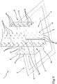
- the system 1 comprises a pole 2 having a main extension axis X.
- the pole 2 can be made of one of the following materials: reinforced concrete (R.C.), prestressed reinforced concrete (P. R. C.), steel, wood.
- the pole 2 has a polygonal section, still more preferably a square or rectangular section.
- the system 1 comprises a foundation plinth 3 comprising a housing seat 4 that is suitable for receiving the pole 2.
- the housing seat 4 of the foundation plinth 3 is a through seat and the pole 2 is suitable for being arranged in the through housing seat 4 in such a manner that, during a configuration of use of the system 1, the pole 2 can be arranged at a set driving depth "h" that is less than an installation depth "H” of the foundation plinth, as illustrated in figure 6 .
- the through housing seat 4 has a shape and dimensions that are such as to enable the pole 2 to slide in the interior thereof.
- the housing seat 4 has a countersink 4a to the centre, as visible in figure 2 .
- the foundation plinth 3 coated with a waterproofing sheath.
- the foundation plinth 3 is provided with positioning rings 5 that are integral with the foundation plinth 3 itself and are configured for being connected by chains or hooks by lifting means, which is not illustrated in the appended figures, to handle the foundation plinth 3.
- the foundation plinth 3 comprises a plurality of feet arranged in the lower surface of the foundation plinth 3, which are not illustrated in the appended figures, which are even more preferably made as one piece with the foundation plinth 3.
- the feet act as spacer elements favouring possible stacking of several foundation plinths 3 during the conveying step, thus safeguarding the structural integrity of the foundation plinths 3.
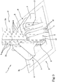
- the system 1 preferably comprises at least one anchoring element 6 configured for anchoring the pole 2 with the foundation plinth 3.
- the anchoring element 6 comprises a first anchoring portion 7 configured for engaging with the foundation plinth 3 and a second anchoring portion 8 configured for engaging with the pole 2.
- the first and/or the second anchoring portion 7, 8 are made of steel.
- the first and second anchoring portion 7, 8 are afforded in a piece.
- the anchoring element 6 is substantially L-shaped.
- the pole 2 has a plurality of recesses 9 on at least one face 2a of the lateral external surface of the pole 2.
- the second anchoring portion 8 has a plurality of protrusions 10 conformed in such a manner as to be coupled respectively with the plurality of recesses 9 for anchoring the second anchoring portion 8 to the pole 2.
- the recesses 9 are protected inside with rubber plug elements (or another material of similar consistency, resilience and section modulus), which are not illustrated, to prevent direct contact between the recesses 9 and the protrusions 10.
- rubber plug elements or another material of similar consistency, resilience and section modulus
- the recesses 9 are configured for increasing the grip of the pole 2 with the terrain.
- the recesses 9 are made with dimensions slightly greater than the protrusions 10; in this manner, a certain clearance is ensured that can facilitate correct positioning of the second anchoring portion 8.
- the first anchoring portion 7 can be anchored to the foundation plinth 3 by first fixing elements 7a.
- first fixing elements 7a pass the upper surface 3a of the foundation plinth 3 and the first anchoring portion 7.
- first fixing elements 7a pass the countersink 4a of the foundation plinth 3 and the first anchoring portion 7.
- the system 1 that is the object of the present invention comprises at least one pair of anchoring elements 6 that are arranged opposite the pole 2, even more preferably two pairs of anchoring elements 6, as illustrated in the appended figures 2-5 .
- the system 1 preferably comprises clamping means 11 to claim the pairs of anchoring elements 6 together.
- the clamping means 11 permits greater stability and solidity in the system 1.
- the clamping means 11 comprises bars 12 (for example of steel and threaded items) that are insertable into gripping slots 13 of the anchoring elements 6 and are clampable to the ends with clamping elements 14 (for example nuts).
- the system 1 comprises a plurality of fixing pins, which are not illustrated in the appended figures, which are suitable for being inserted into the pole 2 and passing respectively inside a plurality of holes 15 made in the second anchoring portion 8, illustrated in figure 2 .
- the pins enable the second anchoring portion 8 to be fixed to the pole 2 without encroaching on the volume surrounding the anchoring portion 8.
- holes are made (for example by drill) inside the pole 2, which are not illustrated in the appended figures, which are filled with thermosetting resin (for example epoxy resin), that following the insertion of the through pins first in the holes 15 and then in the holes of the pole 2, makes the pins integral with the pole 2.
- the system 1 preferably comprises at least one reinforcing plate 16 suitable for being arranged between the first anchoring portion 7 and the second anchoring portion 8 perpendicularly to the face 2a of the lateral external surface of the pole 2 and parallel to the main extension direction X of the pole 2.
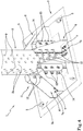
- the system 1 preferably comprises at least one closing element 17 for closing the anchoring element 6.
- the closing element 17 is made of plastic and is suitably shaped to be restrained by pressure on the anchoring elements 6. According to a further aspect of the invention, a method is provided for realizing a system 1 comprising the steps of:
- the fact of being able to insert the through pole 2 inside the foundation plinth 3 enables a structure 1 to be obtained that has great stability features.
- the step of arranging the through pole 2 for the through housing seat 4 comprises the subphase of lowering from above the foundation plinth 3 on the pole 2.
- the method can comprise the subphase of making a small foundation excavation S around the pole 2, which can be achieved for example with small excavating machine, the excavation S being suitable for housing the foundation plinth 3.
- the method comprises the step of anchoring the pole 2 to the foundation plinth 3.
- FIG 2 a step is illustrated of fitting the second anchoring portions 8 that can be advantageously mounted at the desired depth on the basis of the geometrical positioning diagram of the recesses 9 on the pole 2.
- FIG 3 a step of fitting the first anchoring portions 7 is illustrated, which can be reinforced by the reinforcing plates 16.
- FIG 5 a final step is illustrated of the method of realizing the system 1 that installs the closing elements 17, owing to which it is possible to protect the closing elements 6 from external agents.
- the pole 2 acts both as a foundation pole, in as much as it is partially underground, and acts as a consolidating pole when it is driven, and acts as a pillar of the building or of the lines (e.g. power and telephone); this element, near ground level, is anchored to a foundation plinth 3 that acts as a stiff confining ring minimizing the horizontal and vertical movements of the vertical bearing element (pole 2) that it controls, with excellent results in antiseismic terms.
- adopting horizontal and/or vertical bracing portals which are not illustrated in the appended figures, which are applied to the above-ground portion of the bearing vertical elements (i.e. of the portion of the poles 2 that protrudes from the terrain) in buildings realized with the technique presented in this invention, contributes significantly to the building achieving the behaviour of an entire stiff body that useful for antiseismic purposes.
- another advantage of the system 1 depends on the fact that the pole 2 can be driven, inserted or installed at lower depths than that of the foundation poles or the consolidating micropoles, so that the pole 2 is more easily extractable in the event of possible removal, without the use of particularly powerful machines, and with a lower environmental impact.
- the coaction of a vertical element (pole 2) and "ring-shaped plinth" (foundation plinth 3) makes the system 1 much stiffer than traditional techniques (simple installation of plinths or another foundation on the poles or on the micropoles); this enables greater performance to be achieved with thinner elements with savings of costs of materials.
- This invention achieves the proposed objects by overcoming the prior-art drawbacks complained about and making available a bearing structural system and a corresponding realization method that combines the advantages of the speed of prefabricated building, the advantages of simplicity of installation that characterizes "pillar-socket plinth” systems, with the advantages of compacting the terrain that is characteristic of driven poles and micropoles.
Landscapes
- Engineering & Computer Science (AREA)
- Structural Engineering (AREA)
- Life Sciences & Earth Sciences (AREA)
- General Life Sciences & Earth Sciences (AREA)
- Mining & Mineral Resources (AREA)
- Paleontology (AREA)
- Civil Engineering (AREA)
- General Engineering & Computer Science (AREA)
- Environmental & Geological Engineering (AREA)
- Joining Of Building Structures In Genera (AREA)
- Foundations (AREA)
Claims (9)
- Tragendes Struktursystem (1) mit einem Pfeiler (2), der eine Haupterstreckungsachse (X) aufweist, und einem Fundamentsockel (3), der einen Sitz für das Gehäuse (4) aufweist, der zur Aufnahme des Pfeilers (2) geeignet ist, der Sitz für das Gehäuse (4) des Fundamentsockels (3) durchgehend ist und der Pfeiler (2) ausgebildet ist, innerhalb des durchgehenden Sitzes für das Gehäuse (4) angeordnet zu werden, so dass der Pfeiler (2) während einer Verwendungskonfiguration des tragenden Struktursystems (1) in einer bestimmten Eindringtiefe (h) platziert werden kann, die niedriger ist als eine Installationstiefe (H) des Fundamentsockels (3), dadurch gekennzeichnet, dass das tragende Struktursystem (1) umfasst:- mindestens ein Paar von Verankerungselementen (6), die in Bezug auf den Pfeiler (2) gegenüberliegend angeordnet sind, vorzugsweise zwei Paare von Verankerungselementen (6), wobei jedes Verankerungselement (6) so konfiguriert ist, dass es den Pfeiler (2) mit dem Fundamentsockel (3) verankert, wobei jedes Verankerungselement (6) jeweils einen ersten Verankerungsabschnitt (7) umfasst, der konfiguriert ist, dass er mit dem Fundamentsockel (3) in Eingriff tritt, und einen zweiten Verankerungsabschnitt (8), der konfiguriert ist, dass er mit dem Pfeiler (2) in Eingriff tritt; und- eine Klemmeinrichtung (11) zum Festklemmen des mindestens einen Paares von Verankerungselementen (6) eines gegen ein anderes, wobei die Klemmeinrichtung (11) Stangen (12) umfasst, die in Greifschlitze (13) der Verankerungselemente (6) einsetzbar sind, wobei die Stangen (12) an ihren Enden mit Klemmelementen (14) festgeklemmt sind.
- Tragendes Struktursystem (1) nach Anspruch 1, wobei der Pfeiler (2) eine Vielzahl von Ausnehmungen (9) auf mindestens einer Seite (2a) der äußeren Seitenfläche des Pfeilers (2) aufweist und wobei der zweite Verankerungsabschnitt (8) eine Vielzahl von Vorsprüngen (10) aufweist, die so geformt sind, dass sie jeweils der Vielzahl von Ausnehmungen (9) entsprechen, damit der zweite Verankerungsabschnitt (8) an dem Pfeiler (2) verankert wird.
- Tragendes Struktursystem (1) nach Anspruch 1 oder 2, wobei der erste und der zweite Verankerungsabschnitt (7, 8) aus einem einzigen Teil bestehen.
- Tragendes Struktursystem (1) nach einem der vorhergehenden Ansprüche, umfassend eine Vielzahl von Befestigungsstiften, die ausgebildet sind, in den Pfeiler (2) eingeführt zu werden und jeweils durch eine Vielzahl von Löchern (15) führen, die in dem zweiten Verankerungsabschnitt (8) ausgebildet sind.
- Tragendes Struktursystem (1) nach einem der vorhergehenden Ansprüche, umfassend mindestens einer Verstärkungsplatte (16), die ausgebildet ist, zwischen dem ersten Verankerungsabschnitt (7) und dem zweiten Verankerungsabschnitt (8) senkrecht zu der mindestens einen Seite (2a) der äußeren Seitenfläche des Pfeilers (2) und parallel zu der Haupterstreckungsrichtung (X) des Pfeilers (2) angeordnet zu werden.
- Tragendes Struktursystem (1) nach einem der vorhergehenden Ansprüche, umfassend mindestens ein Verschlusselement (17) des Verankerungselements (6).
- Tragendes Struktursystem (1) nach einem der Ansprüche 1 bis 6, wobei das mindestens eine Verankerungselement (6) im Wesentlichen "L"-förmig ist.
- Verfahren zur Herstellung eines tragenden Struktursystems (1) umfassend die nachfolgenden Schritte:- Vorbereiten eines Pfeilers (2),- Einsetzen des Pfeilers (2) in den Boden (T) mit einer bestimmten Eindringtiefe (h),- Vorbereiten eines Fundamentsockels (3) mit einem durchgehenden Sitz für das Gehäuse (4), der zur Aufnahme des durchgehenden Pfeilers (2) geeignet ist,- Anordnen des Pfeilers (2), der durch das durchgehende Gehäuse (4) hindurchgeht,- Anordnen des Fundamentsockels (3) in einer Einbautiefe (H), die größer ist als die Eindringtiefe (h) des Pfeilers (2);- Verankern des Pfeilers (2) an dem Fundamentsockel (3) durch Bereitstellen von mindestens einem Paar von Verankerungselementen (6), die in Bezug auf den Pfeiler (2) gegenüberliegend angeordnet sind, vorzugsweise zwei Paaren von Verankerungselementen (6); wobei der Verankerungsschritt einen Teilschritt des Verankerns jeweiliger erster Verankerungsabschnitte (7) der Verankerungselemente (6) mit dem Fundamentsockel (3) und einen Teilschritt des Verankerns jeweiliger zweiter Verankerungsabschnitte (8) der Verankerungselemente (6) mit dem Pfeiler (2) umfasst;- Festklemmen des mindestens einen Paares von Verankerungselementen (6) eines gegen ein anderes durch Einführen von Stangen (12) in Greifschlitze (13) der Verankerungselemente (6) und Festklemmen der Stangen (12) an ihren Enden mit Klemmelementen (14).
- Verfahren zur Realisierung eines tragenden Struktursystems (1) nach Anspruch 8, wobei der Schritt des Anordnens des Pfeilers (2), der durch den durchgehenden Sitz für das Gehäuse (4) hindurchgeht, den Teilschritt des Absenkens des Fundamentsockels (3) von oben nach unten auf den Pfeiler (2) umfasst.
Applications Claiming Priority (1)
| Application Number | Priority Date | Filing Date | Title |
|---|---|---|---|
| ITUA2016A002108A ITUA20162108A1 (it) | 2016-03-30 | 2016-03-30 | Sistema strutturale portante e relativo metodo di realizzazione |
Publications (2)
| Publication Number | Publication Date |
|---|---|
| EP3225746A1 EP3225746A1 (de) | 2017-10-04 |
| EP3225746B1 true EP3225746B1 (de) | 2021-10-13 |
Family
ID=56296954
Family Applications (1)
| Application Number | Title | Priority Date | Filing Date |
|---|---|---|---|
| EP17163516.2A Active EP3225746B1 (de) | 2016-03-30 | 2017-03-29 | Tragstruktur |
Country Status (4)
| Country | Link |
|---|---|
| EP (1) | EP3225746B1 (de) |
| ES (1) | ES2903095T3 (de) |
| IT (1) | ITUA20162108A1 (de) |
| MA (1) | MA42956A (de) |
Families Citing this family (4)
| Publication number | Priority date | Publication date | Assignee | Title |
|---|---|---|---|---|
| EP4053343B1 (de) * | 2021-03-01 | 2025-08-20 | BTE Stelcon GmbH | Mobiles fundament |
| CN112982473B (zh) * | 2021-03-04 | 2022-08-30 | 北京工业大学 | 一种无粘结预制装配式框架建筑基础节点及其连接方法 |
| CN113309115A (zh) * | 2021-06-04 | 2021-08-27 | 广州市盾建建设有限公司 | 一种利用支护水平钢管支撑与特殊格构立柱连接以此减小立柱长细比的新型连接方式 |
| IT202100023312A1 (it) * | 2021-09-09 | 2023-03-09 | Fantasia S R L | Dispositivo per il rinforzo metallico strutturale di pali ferroviari esistenti e metodo di installazione associato |
Citations (1)
| Publication number | Priority date | Publication date | Assignee | Title |
|---|---|---|---|---|
| NL9100680A (nl) * | 1991-04-18 | 1992-11-16 | Zeus Beton Bv | Fundatiepaal en werkwijze voor het in de grond aanbrengen daarvan. |
Family Cites Families (1)
| Publication number | Priority date | Publication date | Assignee | Title |
|---|---|---|---|---|
| US7827747B2 (en) * | 2006-07-11 | 2010-11-09 | George Glen R | Footing form for upright structural members of buildings |
-
2016
- 2016-03-30 IT ITUA2016A002108A patent/ITUA20162108A1/it unknown
-
2017
- 2017-03-29 MA MA042956A patent/MA42956A/fr unknown
- 2017-03-29 ES ES17163516T patent/ES2903095T3/es active Active
- 2017-03-29 EP EP17163516.2A patent/EP3225746B1/de active Active
Patent Citations (1)
| Publication number | Priority date | Publication date | Assignee | Title |
|---|---|---|---|---|
| NL9100680A (nl) * | 1991-04-18 | 1992-11-16 | Zeus Beton Bv | Fundatiepaal en werkwijze voor het in de grond aanbrengen daarvan. |
Also Published As
| Publication number | Publication date |
|---|---|
| ES2903095T3 (es) | 2022-03-31 |
| ITUA20162108A1 (it) | 2017-09-30 |
| MA42956A (fr) | 2021-06-02 |
| EP3225746A1 (de) | 2017-10-04 |
Similar Documents
| Publication | Publication Date | Title |
|---|---|---|
| US6074133A (en) | Adjustable foundation piering system | |
| US20140270990A1 (en) | Precast concrete retaining wall | |
| EP3225746B1 (de) | Tragstruktur | |
| US20120155968A1 (en) | Construction method of cellar for building completed | |
| KR20130081971A (ko) | 프리캐스트 콘크리트 벽체 및 이를 사용한 지하구조물 영구벽체 시공 방법 | |
| KR101394235B1 (ko) | 대심도 연약지반용 복합 파일 시공 방법 | |
| CN101240550A (zh) | 格构式钢柱塔吊基础座的施工方法 | |
| KR20130006420A (ko) | 신설 지하 구조물의 시공 방법 | |
| JP6632028B2 (ja) | コンクリート組立擁壁 | |
| KR101300785B1 (ko) | 강화 플라스틱 토류판 | |
| KR101181619B1 (ko) | 어스앵커의 재인장을 통한 대규모 지하구조물 높은 옹벽의 축조 공법 | |
| KR101721451B1 (ko) | 도로 침하 방지패널 | |
| KR20020002145A (ko) | 다단식 옹벽용 기초블록 및 그를 이용한 상층부 옹벽의기초지반 보강공법 | |
| JP2015183366A (ja) | 盛土構造体の構造および構築方法 | |
| JP2011157719A (ja) | 山留め工法 | |
| JP2001303592A (ja) | ブロックの設置固定工法 | |
| CN212336065U (zh) | 适用于地下井筒群施工的导沉系统 | |
| KR102123666B1 (ko) | 건축기초시스템에 있어 임플란트식 파일 설치구 및 이를 이용한 임플란트식 파일공법 | |
| JP4968676B2 (ja) | 増杭による杭基礎補強工法 | |
| EP1405952B1 (de) | Verfahren zum Erstellen einer Verankerung unter einem bestehenden Gebäude | |
| JP4856737B2 (ja) | 既設家屋の基礎補強工法 | |
| JP4146250B2 (ja) | オープンケーソンの底盤築造方法 | |
| JP4423390B2 (ja) | 斜面保護擁壁の施工法 | |
| KR100631362B1 (ko) | 보호대상구체에 지지되는 의존 지하벽 | |
| JP2005180015A (ja) | 不等沈下基盤改良工法および不等沈下基礎改良構造体 |
Legal Events
| Date | Code | Title | Description |
|---|---|---|---|
| PUAI | Public reference made under article 153(3) epc to a published international application that has entered the european phase |
Free format text: ORIGINAL CODE: 0009012 |
|
| STAA | Information on the status of an ep patent application or granted ep patent |
Free format text: STATUS: THE APPLICATION HAS BEEN PUBLISHED |
|
| AK | Designated contracting states |
Kind code of ref document: A1 Designated state(s): AL AT BE BG CH CY CZ DE DK EE ES FI FR GB GR HR HU IE IS IT LI LT LU LV MC MK MT NL NO PL PT RO RS SE SI SK SM TR |
|
| AX | Request for extension of the european patent |
Extension state: BA ME |
|
| STAA | Information on the status of an ep patent application or granted ep patent |
Free format text: STATUS: REQUEST FOR EXAMINATION WAS MADE |
|
| 17P | Request for examination filed |
Effective date: 20180207 |
|
| RAV | Requested validation state of the european patent: fee paid |
Extension state: MA Effective date: 20180207 Extension state: MD Effective date: 20180207 |
|
| RAX | Requested extension states of the european patent have changed |
Extension state: ME Payment date: 20180207 Extension state: BA Payment date: 20180207 |
|
| RBV | Designated contracting states (corrected) |
Designated state(s): AL AT BE BG CH CY CZ DE DK EE ES FI FR GB GR HR HU IE IS IT LI LT LU LV MC MK MT NL NO PL PT RO RS SE SI SK SM TR |
|
| STAA | Information on the status of an ep patent application or granted ep patent |
Free format text: STATUS: EXAMINATION IS IN PROGRESS |
|
| 17Q | First examination report despatched |
Effective date: 20180628 |
|
| RIC1 | Information provided on ipc code assigned before grant |
Ipc: E02D 27/35 20060101ALI20210309BHEP Ipc: E02D 27/34 20060101ALI20210309BHEP Ipc: E02D 27/01 20060101AFI20210309BHEP |
|
| REG | Reference to a national code |
Ref country code: DE Ref legal event code: R079 Ref document number: 602017047445 Country of ref document: DE Free format text: PREVIOUS MAIN CLASS: E02D0027160000 Ipc: E02D0027420000 |
|
| GRAP | Despatch of communication of intention to grant a patent |
Free format text: ORIGINAL CODE: EPIDOSNIGR1 |
|
| STAA | Information on the status of an ep patent application or granted ep patent |
Free format text: STATUS: GRANT OF PATENT IS INTENDED |
|
| RIC1 | Information provided on ipc code assigned before grant |
Ipc: E02D 27/42 20060101AFI20210415BHEP |
|
| INTG | Intention to grant announced |
Effective date: 20210506 |
|
| GRAS | Grant fee paid |
Free format text: ORIGINAL CODE: EPIDOSNIGR3 |
|
| GRAA | (expected) grant |
Free format text: ORIGINAL CODE: 0009210 |
|
| STAA | Information on the status of an ep patent application or granted ep patent |
Free format text: STATUS: THE PATENT HAS BEEN GRANTED |
|
| AK | Designated contracting states |
Kind code of ref document: B1 Designated state(s): AL AT BE BG CH CY CZ DE DK EE ES FI FR GB GR HR HU IE IS IT LI LT LU LV MC MK MT NL NO PL PT RO RS SE SI SK SM TR |
|
| REG | Reference to a national code |
Ref country code: GB Ref legal event code: FG4D |
|
| REG | Reference to a national code |
Ref country code: CH Ref legal event code: EP |
|
| REG | Reference to a national code |
Ref country code: DE Ref legal event code: R096 Ref document number: 602017047445 Country of ref document: DE |
|
| REG | Reference to a national code |
Ref country code: IE Ref legal event code: FG4D |
|
| REG | Reference to a national code |
Ref country code: AT Ref legal event code: REF Ref document number: 1438285 Country of ref document: AT Kind code of ref document: T Effective date: 20211115 |
|
| REG | Reference to a national code |
Ref country code: NL Ref legal event code: FP |
|
| REG | Reference to a national code |
Ref country code: LT Ref legal event code: MG9D |
|
| REG | Reference to a national code |
Ref country code: AT Ref legal event code: MK05 Ref document number: 1438285 Country of ref document: AT Kind code of ref document: T Effective date: 20211013 |
|
| REG | Reference to a national code |
Ref country code: ES Ref legal event code: FG2A Ref document number: 2903095 Country of ref document: ES Kind code of ref document: T3 Effective date: 20220331 |
|
| PG25 | Lapsed in a contracting state [announced via postgrant information from national office to epo] |
Ref country code: RS Free format text: LAPSE BECAUSE OF FAILURE TO SUBMIT A TRANSLATION OF THE DESCRIPTION OR TO PAY THE FEE WITHIN THE PRESCRIBED TIME-LIMIT Effective date: 20211013 Ref country code: LT Free format text: LAPSE BECAUSE OF FAILURE TO SUBMIT A TRANSLATION OF THE DESCRIPTION OR TO PAY THE FEE WITHIN THE PRESCRIBED TIME-LIMIT Effective date: 20211013 Ref country code: FI Free format text: LAPSE BECAUSE OF FAILURE TO SUBMIT A TRANSLATION OF THE DESCRIPTION OR TO PAY THE FEE WITHIN THE PRESCRIBED TIME-LIMIT Effective date: 20211013 Ref country code: BG Free format text: LAPSE BECAUSE OF FAILURE TO SUBMIT A TRANSLATION OF THE DESCRIPTION OR TO PAY THE FEE WITHIN THE PRESCRIBED TIME-LIMIT Effective date: 20220113 Ref country code: AT Free format text: LAPSE BECAUSE OF FAILURE TO SUBMIT A TRANSLATION OF THE DESCRIPTION OR TO PAY THE FEE WITHIN THE PRESCRIBED TIME-LIMIT Effective date: 20211013 |
|
| PG25 | Lapsed in a contracting state [announced via postgrant information from national office to epo] |
Ref country code: IS Free format text: LAPSE BECAUSE OF FAILURE TO SUBMIT A TRANSLATION OF THE DESCRIPTION OR TO PAY THE FEE WITHIN THE PRESCRIBED TIME-LIMIT Effective date: 20220213 Ref country code: SE Free format text: LAPSE BECAUSE OF FAILURE TO SUBMIT A TRANSLATION OF THE DESCRIPTION OR TO PAY THE FEE WITHIN THE PRESCRIBED TIME-LIMIT Effective date: 20211013 Ref country code: PT Free format text: LAPSE BECAUSE OF FAILURE TO SUBMIT A TRANSLATION OF THE DESCRIPTION OR TO PAY THE FEE WITHIN THE PRESCRIBED TIME-LIMIT Effective date: 20220214 Ref country code: PL Free format text: LAPSE BECAUSE OF FAILURE TO SUBMIT A TRANSLATION OF THE DESCRIPTION OR TO PAY THE FEE WITHIN THE PRESCRIBED TIME-LIMIT Effective date: 20211013 Ref country code: NO Free format text: LAPSE BECAUSE OF FAILURE TO SUBMIT A TRANSLATION OF THE DESCRIPTION OR TO PAY THE FEE WITHIN THE PRESCRIBED TIME-LIMIT Effective date: 20220113 Ref country code: LV Free format text: LAPSE BECAUSE OF FAILURE TO SUBMIT A TRANSLATION OF THE DESCRIPTION OR TO PAY THE FEE WITHIN THE PRESCRIBED TIME-LIMIT Effective date: 20211013 Ref country code: HR Free format text: LAPSE BECAUSE OF FAILURE TO SUBMIT A TRANSLATION OF THE DESCRIPTION OR TO PAY THE FEE WITHIN THE PRESCRIBED TIME-LIMIT Effective date: 20211013 Ref country code: GR Free format text: LAPSE BECAUSE OF FAILURE TO SUBMIT A TRANSLATION OF THE DESCRIPTION OR TO PAY THE FEE WITHIN THE PRESCRIBED TIME-LIMIT Effective date: 20220114 |
|
| REG | Reference to a national code |
Ref country code: DE Ref legal event code: R097 Ref document number: 602017047445 Country of ref document: DE |
|
| PG25 | Lapsed in a contracting state [announced via postgrant information from national office to epo] |
Ref country code: SM Free format text: LAPSE BECAUSE OF FAILURE TO SUBMIT A TRANSLATION OF THE DESCRIPTION OR TO PAY THE FEE WITHIN THE PRESCRIBED TIME-LIMIT Effective date: 20211013 Ref country code: SK Free format text: LAPSE BECAUSE OF FAILURE TO SUBMIT A TRANSLATION OF THE DESCRIPTION OR TO PAY THE FEE WITHIN THE PRESCRIBED TIME-LIMIT Effective date: 20211013 Ref country code: RO Free format text: LAPSE BECAUSE OF FAILURE TO SUBMIT A TRANSLATION OF THE DESCRIPTION OR TO PAY THE FEE WITHIN THE PRESCRIBED TIME-LIMIT Effective date: 20211013 Ref country code: EE Free format text: LAPSE BECAUSE OF FAILURE TO SUBMIT A TRANSLATION OF THE DESCRIPTION OR TO PAY THE FEE WITHIN THE PRESCRIBED TIME-LIMIT Effective date: 20211013 Ref country code: DK Free format text: LAPSE BECAUSE OF FAILURE TO SUBMIT A TRANSLATION OF THE DESCRIPTION OR TO PAY THE FEE WITHIN THE PRESCRIBED TIME-LIMIT Effective date: 20211013 Ref country code: CZ Free format text: LAPSE BECAUSE OF FAILURE TO SUBMIT A TRANSLATION OF THE DESCRIPTION OR TO PAY THE FEE WITHIN THE PRESCRIBED TIME-LIMIT Effective date: 20211013 |
|
| VS25 | Lapsed in a validation state [announced via postgrant information from nat. office to epo] |
Ref country code: MD Free format text: LAPSE BECAUSE OF FAILURE TO SUBMIT A TRANSLATION OF THE DESCRIPTION OR TO PAY THE FEE WITHIN THE PRESCRIBED TIME-LIMIT Effective date: 20211013 |
|
| PLBE | No opposition filed within time limit |
Free format text: ORIGINAL CODE: 0009261 |
|
| STAA | Information on the status of an ep patent application or granted ep patent |
Free format text: STATUS: NO OPPOSITION FILED WITHIN TIME LIMIT |
|
| 26N | No opposition filed |
Effective date: 20220714 |
|
| PG25 | Lapsed in a contracting state [announced via postgrant information from national office to epo] |
Ref country code: MC Free format text: LAPSE BECAUSE OF FAILURE TO SUBMIT A TRANSLATION OF THE DESCRIPTION OR TO PAY THE FEE WITHIN THE PRESCRIBED TIME-LIMIT Effective date: 20211013 Ref country code: AL Free format text: LAPSE BECAUSE OF FAILURE TO SUBMIT A TRANSLATION OF THE DESCRIPTION OR TO PAY THE FEE WITHIN THE PRESCRIBED TIME-LIMIT Effective date: 20211013 |
|
| PG25 | Lapsed in a contracting state [announced via postgrant information from national office to epo] |
Ref country code: SI Free format text: LAPSE BECAUSE OF FAILURE TO SUBMIT A TRANSLATION OF THE DESCRIPTION OR TO PAY THE FEE WITHIN THE PRESCRIBED TIME-LIMIT Effective date: 20211013 |
|
| REG | Reference to a national code |
Ref country code: BE Ref legal event code: MM Effective date: 20220331 |
|
| PG25 | Lapsed in a contracting state [announced via postgrant information from national office to epo] |
Ref country code: LU Free format text: LAPSE BECAUSE OF NON-PAYMENT OF DUE FEES Effective date: 20220329 Ref country code: IE Free format text: LAPSE BECAUSE OF NON-PAYMENT OF DUE FEES Effective date: 20220329 |
|
| PG25 | Lapsed in a contracting state [announced via postgrant information from national office to epo] |
Ref country code: BE Free format text: LAPSE BECAUSE OF NON-PAYMENT OF DUE FEES Effective date: 20220331 |
|
| REG | Reference to a national code |
Ref country code: DE Ref legal event code: R082 Ref document number: 602017047445 Country of ref document: DE Representative=s name: WOERZ PATENTANWAELTE PARTNERSCHAFTSGESELLSCHAF, DE |
|
| P01 | Opt-out of the competence of the unified patent court (upc) registered |
Effective date: 20230527 |
|
| PG25 | Lapsed in a contracting state [announced via postgrant information from national office to epo] |
Ref country code: HU Free format text: LAPSE BECAUSE OF FAILURE TO SUBMIT A TRANSLATION OF THE DESCRIPTION OR TO PAY THE FEE WITHIN THE PRESCRIBED TIME-LIMIT; INVALID AB INITIO Effective date: 20170329 |
|
| PG25 | Lapsed in a contracting state [announced via postgrant information from national office to epo] |
Ref country code: MK Free format text: LAPSE BECAUSE OF FAILURE TO SUBMIT A TRANSLATION OF THE DESCRIPTION OR TO PAY THE FEE WITHIN THE PRESCRIBED TIME-LIMIT Effective date: 20211013 Ref country code: CY Free format text: LAPSE BECAUSE OF FAILURE TO SUBMIT A TRANSLATION OF THE DESCRIPTION OR TO PAY THE FEE WITHIN THE PRESCRIBED TIME-LIMIT Effective date: 20211013 |
|
| VS25 | Lapsed in a validation state [announced via postgrant information from nat. office to epo] |
Ref country code: MA Free format text: LAPSE BECAUSE OF FAILURE TO SUBMIT A TRANSLATION OF THE DESCRIPTION OR TO PAY THE FEE WITHIN THE PRESCRIBED TIME-LIMIT Effective date: 20211013 |
|
| PG25 | Lapsed in a contracting state [announced via postgrant information from national office to epo] |
Ref country code: MT Free format text: LAPSE BECAUSE OF FAILURE TO SUBMIT A TRANSLATION OF THE DESCRIPTION OR TO PAY THE FEE WITHIN THE PRESCRIBED TIME-LIMIT Effective date: 20211013 |
|
| PGFP | Annual fee paid to national office [announced via postgrant information from national office to epo] |
Ref country code: ES Payment date: 20250401 Year of fee payment: 9 |
|
| PGFP | Annual fee paid to national office [announced via postgrant information from national office to epo] |
Ref country code: IT Payment date: 20250331 Year of fee payment: 9 |
|
| PGFP | Annual fee paid to national office [announced via postgrant information from national office to epo] |
Ref country code: CH Payment date: 20250411 Year of fee payment: 9 |
|
| REG | Reference to a national code |
Ref country code: CH Ref legal event code: U11 Free format text: ST27 STATUS EVENT CODE: U-0-0-U10-U11 (AS PROVIDED BY THE NATIONAL OFFICE) Effective date: 20260401 |
|
| PGFP | Annual fee paid to national office [announced via postgrant information from national office to epo] |
Ref country code: GB Payment date: 20260327 Year of fee payment: 10 |
|
| PGFP | Annual fee paid to national office [announced via postgrant information from national office to epo] |
Ref country code: DE Payment date: 20260327 Year of fee payment: 10 |
|
| PGFP | Annual fee paid to national office [announced via postgrant information from national office to epo] |
Ref country code: NL Payment date: 20260326 Year of fee payment: 10 |
|
| PGFP | Annual fee paid to national office [announced via postgrant information from national office to epo] |
Ref country code: FR Payment date: 20260325 Year of fee payment: 10 |
|
| PGFP | Annual fee paid to national office [announced via postgrant information from national office to epo] |
Ref country code: TR Payment date: 20260310 Year of fee payment: 10 |