EP3225760A1 - Structure de paroi à supports multiples - Google Patents
Structure de paroi à supports multiples Download PDFInfo
- Publication number
- EP3225760A1 EP3225760A1 EP15863278.6A EP15863278A EP3225760A1 EP 3225760 A1 EP3225760 A1 EP 3225760A1 EP 15863278 A EP15863278 A EP 15863278A EP 3225760 A1 EP3225760 A1 EP 3225760A1
- Authority
- EP
- European Patent Office
- Prior art keywords
- projective
- insertions
- upward
- plates
- lattice
- Prior art date
- Legal status (The legal status is an assumption and is not a legal conclusion. Google has not performed a legal analysis and makes no representation as to the accuracy of the status listed.)
- Granted
Links
- 238000003780 insertion Methods 0.000 claims abstract description 92
- 230000037431 insertion Effects 0.000 claims abstract description 92
- 230000003014 reinforcing effect Effects 0.000 claims abstract description 68
- 210000004027 cell Anatomy 0.000 claims description 9
- 210000002763 pyramidal cell Anatomy 0.000 claims description 8
- 239000010432 diamond Substances 0.000 claims description 4
- 229910003460 diamond Inorganic materials 0.000 claims description 3
- 230000001681 protective effect Effects 0.000 claims 1
- 238000009434 installation Methods 0.000 description 14
- 239000000057 synthetic resin Substances 0.000 description 12
- 229920003002 synthetic resin Polymers 0.000 description 12
- 230000000694 effects Effects 0.000 description 11
- 238000009413 insulation Methods 0.000 description 6
- 238000003754 machining Methods 0.000 description 6
- 239000000853 adhesive Substances 0.000 description 4
- 230000001070 adhesive effect Effects 0.000 description 4
- 239000000463 material Substances 0.000 description 3
- 238000000034 method Methods 0.000 description 3
- 238000000465 moulding Methods 0.000 description 3
- 238000005476 soldering Methods 0.000 description 3
- 230000008878 coupling Effects 0.000 description 2
- 238000010168 coupling process Methods 0.000 description 2
- 238000005859 coupling reaction Methods 0.000 description 2
- 238000004519 manufacturing process Methods 0.000 description 2
- 238000003466 welding Methods 0.000 description 2
- 241000490025 Schefflera digitata Species 0.000 description 1
- 238000010276 construction Methods 0.000 description 1
- 238000005520 cutting process Methods 0.000 description 1
- 230000007547 defect Effects 0.000 description 1
- 235000015250 liver sausages Nutrition 0.000 description 1
- 239000002184 metal Substances 0.000 description 1
- 239000000088 plastic resin Substances 0.000 description 1
- 239000011120 plywood Substances 0.000 description 1
- 239000000047 product Substances 0.000 description 1
- 239000011265 semifinished product Substances 0.000 description 1
- 238000000926 separation method Methods 0.000 description 1
- 229910000679 solder Inorganic materials 0.000 description 1
- 239000004575 stone Substances 0.000 description 1
- 229920002994 synthetic fiber Polymers 0.000 description 1
Images






Classifications
-
- E—FIXED CONSTRUCTIONS
- E04—BUILDING
- E04C—STRUCTURAL ELEMENTS; BUILDING MATERIALS
- E04C2/00—Building elements of relatively thin form for the construction of parts of buildings, e.g. sheet materials, slabs, or panels
- E04C2/30—Building elements of relatively thin form for the construction of parts of buildings, e.g. sheet materials, slabs, or panels characterised by the shape or structure
- E04C2/32—Building elements of relatively thin form for the construction of parts of buildings, e.g. sheet materials, slabs, or panels characterised by the shape or structure formed of corrugated or otherwise indented sheet-like material; composed of such layers with or without layers of flat sheet-like material
- E04C2/326—Building elements of relatively thin form for the construction of parts of buildings, e.g. sheet materials, slabs, or panels characterised by the shape or structure formed of corrugated or otherwise indented sheet-like material; composed of such layers with or without layers of flat sheet-like material with corrugations, incisions or reliefs in more than one direction of the element
-
- E—FIXED CONSTRUCTIONS
- E04—BUILDING
- E04C—STRUCTURAL ELEMENTS; BUILDING MATERIALS
- E04C2/00—Building elements of relatively thin form for the construction of parts of buildings, e.g. sheet materials, slabs, or panels
- E04C2/30—Building elements of relatively thin form for the construction of parts of buildings, e.g. sheet materials, slabs, or panels characterised by the shape or structure
- E04C2/34—Building elements of relatively thin form for the construction of parts of buildings, e.g. sheet materials, slabs, or panels characterised by the shape or structure composed of two or more spaced sheet-like parts
- E04C2/3405—Building elements of relatively thin form for the construction of parts of buildings, e.g. sheet materials, slabs, or panels characterised by the shape or structure composed of two or more spaced sheet-like parts spaced apart by profiled spacer sheets
-
- E—FIXED CONSTRUCTIONS
- E04—BUILDING
- E04C—STRUCTURAL ELEMENTS; BUILDING MATERIALS
- E04C2/00—Building elements of relatively thin form for the construction of parts of buildings, e.g. sheet materials, slabs, or panels
- E04C2/30—Building elements of relatively thin form for the construction of parts of buildings, e.g. sheet materials, slabs, or panels characterised by the shape or structure
- E04C2/34—Building elements of relatively thin form for the construction of parts of buildings, e.g. sheet materials, slabs, or panels characterised by the shape or structure composed of two or more spaced sheet-like parts
-
- E—FIXED CONSTRUCTIONS
- E04—BUILDING
- E04B—GENERAL BUILDING CONSTRUCTIONS; WALLS, e.g. PARTITIONS; ROOFS; FLOORS; CEILINGS; INSULATION OR OTHER PROTECTION OF BUILDINGS
- E04B1/00—Constructions in general; Structures which are not restricted either to walls, e.g. partitions, or floors or ceilings or roofs
- E04B1/62—Insulation or other protection; Elements or use of specified material therefor
- E04B1/74—Heat, sound or noise insulation, absorption, or reflection; Other building methods affording favourable thermal or acoustical conditions, e.g. accumulating of heat within walls
- E04B1/88—Insulating elements for both heat and sound
- E04B1/90—Insulating elements for both heat and sound slab-shaped
-
- E—FIXED CONSTRUCTIONS
- E04—BUILDING
- E04C—STRUCTURAL ELEMENTS; BUILDING MATERIALS
- E04C2/00—Building elements of relatively thin form for the construction of parts of buildings, e.g. sheet materials, slabs, or panels
- E04C2/30—Building elements of relatively thin form for the construction of parts of buildings, e.g. sheet materials, slabs, or panels characterised by the shape or structure
- E04C2/32—Building elements of relatively thin form for the construction of parts of buildings, e.g. sheet materials, slabs, or panels characterised by the shape or structure formed of corrugated or otherwise indented sheet-like material; composed of such layers with or without layers of flat sheet-like material
-
- E—FIXED CONSTRUCTIONS
- E04—BUILDING
- E04C—STRUCTURAL ELEMENTS; BUILDING MATERIALS
- E04C2/00—Building elements of relatively thin form for the construction of parts of buildings, e.g. sheet materials, slabs, or panels
- E04C2/30—Building elements of relatively thin form for the construction of parts of buildings, e.g. sheet materials, slabs, or panels characterised by the shape or structure
- E04C2/34—Building elements of relatively thin form for the construction of parts of buildings, e.g. sheet materials, slabs, or panels characterised by the shape or structure composed of two or more spaced sheet-like parts
- E04C2/36—Building elements of relatively thin form for the construction of parts of buildings, e.g. sheet materials, slabs, or panels characterised by the shape or structure composed of two or more spaced sheet-like parts spaced apart by transversely-placed strip material, e.g. honeycomb panels
- E04C2/365—Building elements of relatively thin form for the construction of parts of buildings, e.g. sheet materials, slabs, or panels characterised by the shape or structure composed of two or more spaced sheet-like parts spaced apart by transversely-placed strip material, e.g. honeycomb panels by honeycomb structures
-
- B—PERFORMING OPERATIONS; TRANSPORTING
- B32—LAYERED PRODUCTS
- B32B—LAYERED PRODUCTS, i.e. PRODUCTS BUILT-UP OF STRATA OF FLAT OR NON-FLAT, e.g. CELLULAR OR HONEYCOMB, FORM
- B32B3/00—Layered products comprising a layer with external or internal discontinuities or unevennesses, or a layer of non-planar shape; Layered products comprising a layer having particular features of form
- B32B3/10—Layered products comprising a layer with external or internal discontinuities or unevennesses, or a layer of non-planar shape; Layered products comprising a layer having particular features of form characterised by a discontinuous layer, i.e. formed of separate pieces of material
- B32B3/12—Layered products comprising a layer with external or internal discontinuities or unevennesses, or a layer of non-planar shape; Layered products comprising a layer having particular features of form characterised by a discontinuous layer, i.e. formed of separate pieces of material characterised by a layer of regularly- arranged cells, e.g. a honeycomb structure
-
- E—FIXED CONSTRUCTIONS
- E04—BUILDING
- E04C—STRUCTURAL ELEMENTS; BUILDING MATERIALS
- E04C2/00—Building elements of relatively thin form for the construction of parts of buildings, e.g. sheet materials, slabs, or panels
- E04C2/30—Building elements of relatively thin form for the construction of parts of buildings, e.g. sheet materials, slabs, or panels characterised by the shape or structure
- E04C2/34—Building elements of relatively thin form for the construction of parts of buildings, e.g. sheet materials, slabs, or panels characterised by the shape or structure composed of two or more spaced sheet-like parts
- E04C2/3405—Building elements of relatively thin form for the construction of parts of buildings, e.g. sheet materials, slabs, or panels characterised by the shape or structure composed of two or more spaced sheet-like parts spaced apart by profiled spacer sheets
- E04C2002/3411—Dimpled spacer sheets
-
- E—FIXED CONSTRUCTIONS
- E04—BUILDING
- E04C—STRUCTURAL ELEMENTS; BUILDING MATERIALS
- E04C2/00—Building elements of relatively thin form for the construction of parts of buildings, e.g. sheet materials, slabs, or panels
- E04C2/30—Building elements of relatively thin form for the construction of parts of buildings, e.g. sheet materials, slabs, or panels characterised by the shape or structure
- E04C2/34—Building elements of relatively thin form for the construction of parts of buildings, e.g. sheet materials, slabs, or panels characterised by the shape or structure composed of two or more spaced sheet-like parts
- E04C2/3405—Building elements of relatively thin form for the construction of parts of buildings, e.g. sheet materials, slabs, or panels characterised by the shape or structure composed of two or more spaced sheet-like parts spaced apart by profiled spacer sheets
- E04C2002/3411—Dimpled spacer sheets
- E04C2002/3422—Dimpled spacer sheets with polygonal dimples
-
- E—FIXED CONSTRUCTIONS
- E04—BUILDING
- E04C—STRUCTURAL ELEMENTS; BUILDING MATERIALS
- E04C2/00—Building elements of relatively thin form for the construction of parts of buildings, e.g. sheet materials, slabs, or panels
- E04C2/30—Building elements of relatively thin form for the construction of parts of buildings, e.g. sheet materials, slabs, or panels characterised by the shape or structure
- E04C2/34—Building elements of relatively thin form for the construction of parts of buildings, e.g. sheet materials, slabs, or panels characterised by the shape or structure composed of two or more spaced sheet-like parts
- E04C2/3405—Building elements of relatively thin form for the construction of parts of buildings, e.g. sheet materials, slabs, or panels characterised by the shape or structure composed of two or more spaced sheet-like parts spaced apart by profiled spacer sheets
- E04C2002/3411—Dimpled spacer sheets
- E04C2002/3433—Dimpled spacer sheets with dimples extending from both sides of the spacer sheet
-
- E—FIXED CONSTRUCTIONS
- E04—BUILDING
- E04C—STRUCTURAL ELEMENTS; BUILDING MATERIALS
- E04C2/00—Building elements of relatively thin form for the construction of parts of buildings, e.g. sheet materials, slabs, or panels
- E04C2/30—Building elements of relatively thin form for the construction of parts of buildings, e.g. sheet materials, slabs, or panels characterised by the shape or structure
- E04C2/34—Building elements of relatively thin form for the construction of parts of buildings, e.g. sheet materials, slabs, or panels characterised by the shape or structure composed of two or more spaced sheet-like parts
- E04C2/3405—Building elements of relatively thin form for the construction of parts of buildings, e.g. sheet materials, slabs, or panels characterised by the shape or structure composed of two or more spaced sheet-like parts spaced apart by profiled spacer sheets
- E04C2002/3411—Dimpled spacer sheets
- E04C2002/3433—Dimpled spacer sheets with dimples extending from both sides of the spacer sheet
- E04C2002/3438—Dimpled spacer sheets with dimples extending from both sides of the spacer sheet with saddle-shaped dimples, e.g. eggcrate type spacer sheets
-
- E—FIXED CONSTRUCTIONS
- E04—BUILDING
- E04C—STRUCTURAL ELEMENTS; BUILDING MATERIALS
- E04C2/00—Building elements of relatively thin form for the construction of parts of buildings, e.g. sheet materials, slabs, or panels
- E04C2/30—Building elements of relatively thin form for the construction of parts of buildings, e.g. sheet materials, slabs, or panels characterised by the shape or structure
- E04C2/34—Building elements of relatively thin form for the construction of parts of buildings, e.g. sheet materials, slabs, or panels characterised by the shape or structure composed of two or more spaced sheet-like parts
- E04C2/3405—Building elements of relatively thin form for the construction of parts of buildings, e.g. sheet materials, slabs, or panels characterised by the shape or structure composed of two or more spaced sheet-like parts spaced apart by profiled spacer sheets
- E04C2002/3472—Building elements of relatively thin form for the construction of parts of buildings, e.g. sheet materials, slabs, or panels characterised by the shape or structure composed of two or more spaced sheet-like parts spaced apart by profiled spacer sheets with multiple layers of profiled spacer sheets
Definitions
- the present invention relates to a multiple support wall structure and, more particularly, to a multiple support wall structure in which an intermediate reinforcing plate and outer top and bottom support plates are combined on both sides of the intermediate reinforcing plate by upward and downward projective insertions of the intermediate reinforcing plate and lattice-shaped projections and rectangular islands of the top and bottom support plates, so applied load is distributed by the upward and downward projective insertions, the lattice-shaped projections, and the rectangular islands, which are fitted to each other to make many contact sides, and large load is distributed by the contact areas, thereby improving the ability to distribute and resist applied load; and the structure is assembled only by fitting without specific machining, so installation is simple, an installation period is reduced, and carrying and installing are easy due to light weight; and many spaces are formed in the multiple structure, an insulation effect is high, soundproof or sound-blocking effect is improved, and the strength is also high.
- plate-shaped support wall structures in general, have honeycomb structures and are made of paper or pulp. According to such a honeycomb structure, the cover plate is supported by vertical middle walls, so the structure is stable and the weight is small. Plate-shaped support wall structures are generally used for doors, internal structures, and outdoor market structures, etc. However, such plate-shaped support wall structures are weak to humidity.
- the sandwich support wall structure has a honeycomb structure composed of two cover plates and walls disposed between the cover plates to make compartments.
- the two cover plates are connected by welding or soldering and the soldering material is distributed uniformly up to the edges of the compartments, so the cover plates are strongly connected to the honeycomb structure. Accordingly, the edges of the compartments are strong, but the walls are supported by the cover plates, so the stability of this hard honeycomb structure fully depends on the cover plates and the stability at the core part of the sandwich support wall structure is small enough to be negligible. Further, there is another defect that the manufacturing cost is high and synthetic materials cannot be used.
- a invention titled "Lightweight construction element in the form of a hollow body contoured honeycomb structure", has been proposed in PCT/DE2000/01683 , but according to this structure, plates are molded, the molded plates undergo precision machining such as cutting, and a process for bonding the semi-finished products that have undergone the precision machining for assembly is performed, so a large amount of manpower and work time is required.
- an object of the present invention is to provide a multiple support wall structure, in which an intermediate reinforcing plate and top and bottom support plates to be fixed to both sides of the intermediate reinforcing plate are combined by applying an adhesive to upward and downward projective insertions of the intermediate reinforcing plate and lattice-shaped projections and rectangular islands of the top and bottom support plates, and then fitting them to each other, so applied load is distributed by the upward and downward projective insertions, the lattice-shaped projections, and the rectangular islands, which are fitted to each other to make many contact sides, and large load is distributed by the contact areas, thereby improving the ability to distribute and resist applied load; and the structure is assembled only by fitting without specific machining, so installation is simple, an installation period is reduced, and carrying and installing are easy due to light weight; and many spaces are formed in the multiple structure, an insulation effect is high, soundproof or sound-blocking effect is improved, and the strength is also high.
- a multiple support wall structure which includes: a pair of top and bottom support plates that has a plurality of rectangular projective islands separated by lattice-shaped projections protruding in the shape of a go board, and protruding upward in the opposite direction to the lattice-shaped projections; and a intermediate reinforcing plate that is disposed between the top and bottom support plates, has upward projective insertions protruding in a shape corresponding to the rectangular islands to be fitted in the rectangular islands of the top support plate, has top grooves formed laterally and longitudinally between the upward projective insertions to fit the lattice-shaped projections, has downward projective insertions formed in the same shape as but in the opposite direction to the upward projective insertions in spaces diagonally adjacent to the upward projective insertions, and has bottom grooves formed laterally and longitudinally between the downward projective insertions.
- the structure includes: the top and bottom support plates that have a plurality of rectangular projective islands and flat cross projections protruding in an assembly direction and formed at the centers of the rectangular islands; and an intermediate reinforcing plate that is inserted between the top and bottom support plates, has upward and downward projective insertions formed to fit the flat cross projections of the top and bottom support plates, and has top and bottom grooves formed laterally and longitudinally between adjacent upward and downward projective insertions.
- the intermediate reinforcing plate and the top and bottom support plates are combined on both sides of the intermediate reinforcing plate by the upward and downward projective insertions and the rectangular islands. Accordingly, applied load is distributed by the portions fitted to each other, thereby improving the ability resist load.
- the structure is assembled only by fitting without specific machining, so installation is simple, an installation period is reduced, the weight is small, and many spaces are formed in the multiple structure, whereby an insulation effect is high, soundproof or sound-blocking effect is improved, and the strength is also high.
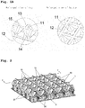
- a multiple support structure A includes: a top support plate 1 that has a plurality of rectangular projective islands separated by lattice-shaped projections 12 protruding in the shape of a go board, and protruding upward in the opposite direction to the lattice-shaped projections 12; an intermediate reinforcing plate 2 that has upward projective insertions 22 protruding in a shape corresponding to the rectangular projective islands 11 to be inserted in the rectangular projective islands 11 of the top support plate 1, has top grooves 21 formed laterally and longitudinally between the upward projective insertions 22 to insert the lattice-shaped projections 12, has downward projective insertions 22' formed in the same shape as but in the opposite direction to the upper projective insertions 22 in spaces diagonally adjacent to the upper projective insertions 22, and has bottom grooves 21' formed laterally and longitudinally between the downward projective insertions 22'; and a bottom support plate 1' that has a plurality of rectangular projective islands 11' separated by lat
- top support plate 1 and the bottom support plate 1' are arranged in opposite direction, but have the same shape, so the top support plate 1 will be mainly described hereafter.
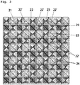
- the upward projective insertions 22 protruding upward are separated by the top grooves 21 formed laterally and longitudinally between the upward projective insertions 22 and receiving the lattice-shaped projections 12, flat cross projections 23 protruding in a shape corresponding to the flat cross projections 13 except the edges are formed on the upward projective insertions 22 to fit the flat cross projections 13 on the top of the rectangular islands 11, and slopes 24 inclined toward the edges are formed at the sides of the flat cross projections 23, so that eight slopes 24 inclined upward are formed at each of the upward projective insertions 22 and the four outer sides of the upward projective insertions 22 are formed in a diamond shape when the upward projective insertions 22 are seen from above. Accordingly, the upward and downward projective insertions 22 and 22' protruding upward and downward, respectively, on the intermediate reinforcing plate 2 are formed such that the diamonds are repeatedly and alternately formed.
- the downward projective insertions 22' protruding downward on the intermediate reinforcing plate 2 are formed in a direction opposite to that of the upward projective insertions 22, but have the same shape as the upward projective insertions 22, so they are not described in detail.
- top and bottom support plates 1 and 1' are used in pairs, have the same configuration, and are coupled to both sides of the intermediate reinforcing plate 2, respectively, but only one of the top and bottom support plates may be used, if necessary.
- the top support plate 1 is formed by molding plastic resin into a thickness of about 0.7mm in this embodiment, but the thickness of the synthetic resin is just an example and it may be possible to mold the synthetic resin into a thickness of 0.3 ⁇ 2mm, depending on the use or strength. In particular, it may be possible to use not only synthetic resin, but a paper plate made of pulp or metallic plate, and a combined configuration in which the intermediate reinforcing plate 2 is made of synthetic resin and the top and bottom plates 1 and 1' are paper plate or metallic plate may be used for convenience.
- Lattice-shaped grooves 15 are formed on the top of the top support plate 1 to correspond to the lattice-shaped projections 12, and a pair of finish plates 3 having a plurality of projective insertions 31 that is inserted in the lattice-shaped grooves 15 may be fixed to finish the top of the top support plate 1, but flat finish plates 3 may be attached to the tops of the flat cross projections 13.
- Projective insertions 31 are longitudinally formed on one of the finish plates 3 fixed to the top support plate 1 and projective insertions 31 are laterally formed on the other finish plate 3, so applied weight can be distributed.
- the finish plates 3 are made of synthetic resin, but the material is not limited thereto and stone or metal may be used.
- the intermediate reinforcing plate 2 is disposed between the pair of top and bottom support plates 1 and 1' in this way.
- the intermediate reinforcing plate 2 is inserted between the top and bottom support plates 1 and 1', the top grooves 11 are arranged to correspond to the gaps of the lattice-shaped projections 12 of the top support plate 1, the upward projective insertions 22 are sequentially formed between adjacent top grooves 21 and protrude as high as the lattice-shaped projections 12, and as shown in FIG. 3 , the downward projective insertions 22' are formed in the opposite direction between the upward projective insertions 22 in the same shape as the upward projective insertions 22.
- the downward projective insertions 22' protruding in the opposite direction, but in the same shape as the upward projective insertions 22 are formed on the opposite side to the upward projective insertions 22 of the intermediate reinforcing plate 2, and the upward projecting insertions 22 and the downward projective insertions 22' are formed in the opposite directions, but in the same shape to fix the top and bottom plates 1 and 1' disposed opposite to each other. Accordingly, they are differentiated by marks ", ', and ", but are given the same number and have the same function.
- the intermediate reinforcing plate 2 is formed by molding synthetic resin with a thickness of about 0.4mm.
- the thickness of the synthetic resin is just an example and it may be possible to mold the synthetic resin into a thickness of 0.3 - 2mm, depending on the use or strength.
- an adhesive is applied to the coupling portions of the top and bottom support plates 1 and 1' and the intermediate reinforcing plate 2 to be assembled and the lattice-shaped projections 12 of the top and bottom support plates 1 and 1' are inserted into the grooves 21 and 21' on the top and bottom of the intermediate reinforcing plate 2.
- the lattice-shaped projections 12 of the top and bottom support plates 1 and 1' are inserted in the top and bottom grooves 21 and 21' of the intermediate reinforcing plate 2, they are in contact with the bottoms of the flat cross projections 13 on the top of the rectangular islands 11 of the top and bottom support plates 1 and 1', whereby the tops of the flat cross projections 23 are brought in contact with each other.
- the top and bottom support plates 1 and 1' and the intermediate reinforcing plate 2 are combined by fitting the lattice-shaped projections 12 of the top support plate 1 into the top and bottom grooves 21 and 21' of the intermediate reinforcing plate 2, in which the upward and downward projective insertions 22 and 22' of the intermediate reinforcing plate 2 are inserted in the rectangular islands 11 of the top and bottom support plates 1 and 1', and the flat cross projections 13 and the flat cross projections 23 of the intermediate reinforcing plate 2 are in surface contact with each other. Accordingly, many surface contact areas are made, so even if large load is applied to the multiple support wall structure A, the load is distributed by the many surface contact portions and the structure can resist large load.
- the lattice-shaped projections 12 of the top and bottom support plates 1 and 1', which are separate parts, and the top and bottom grooves 21 and 21' of the intermediate reinforcing plate 2 are in surface contact with each other;
- the slopes 14 of the rectangular islands 11 of the top and bottom support plates 1 and 1' and the slopes 24 of the upward and downward projective insertions 22 and 22' of the intermediate reinforcing plate 2 are in surface contact with each other;
- the flat cross projections 13 on the tops of the rectangular islands 11 of the top and bottom support plates 1 and 1' are in surface contact with the flat cross projections 23 of the upward and downward projective insertions 22 and 22' of the intermediate reinforcing plate 2, so surface contact is made at many portions.
- the multiple support wall structure A according to the first embodiment of the present invention is assembled only by fitting the top and bottom support plates 1 and 1' and the intermediate reinforcing plate 2 without specific machining, so installation is simple and installation time is short. Accordingly, manpower for installation is considerably saved, so the installation costs are also reduced.
- a plurality of multiple support wall structures A according to the first embodiment of the present invention is each assembled in a size of 1m width and 1.5m length and laterally sequentially arranged at the positions indicated by solid lines. Further, a plurality of multiple support wall structures A is laterally arranged to overlap the above arrangement at the positions indicated by two-dot chain lines at the middle portion, so indefinite expansion can be sequentially achieved to acquire necessary spaces. Accordingly, limits in installation space can be removed and they can be installed in a wide area.
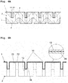
- the finish plates 3 are fixed to the top and bottom support pates 1 and 1' by the lattice-shaped grooves 15 on the top and the bottom of the top and bottom support plates 1 and 1'.
- the finish plate 3 having the longitudinal projective insertions 31 is fixed to the upper support plate 1 and the other finish plate 3 having the lateral projective insertions 31 is fixed to the lower support plate 1', the strength is further increased, so even if large load is applied, it is possible to resist the load by distributing the load.
- FIG. 5B when the flat finish plates 3 can be bonded to the top and bottom support plates 1 and 1' by applying an adhesive to the flat cross projections 13, the multiple support wall structure A can be more easily manufactured.
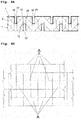
- the multiple support wall structure A according to the first embodiment of the present invention having the structure described above is assembled by applying an adhesive, fitting the lattice-shaped projections 12 in the top and bottom grooves 21 and 21', and the bonding them, but as shown in FIG. 6A , when the plates are made of different materials and difficult to bond, it may be possible to more strongly combined them using bolts 4. Alternatively, it may be possible to combine the plates by fitting the lattice-shaped projections 12 in the top and bottom grooves 21 and 21', fixing them with bolts 4, and then riveting or welding them. Further, as shown in FIG.
- FIG. 7A is an exploded perspective view of a multiple support wall structure according to a second embodiment of the present invention in which a center support member 5 is disposed at the center to increase the strength of the multiple support wall structure, intermediate reinforcing plates 2 are disposed over and under the center support member 5, respectively, and finish plates 3 are coupled or bonded to the intermediate reinforcing plate 2, respectively.
- top rectangular grooves 50 recessed downward to insert downward projective insertions 22' on the bottom of the intermediate reinforcing plate 2 over the center support member 5 are formed on the top
- bottom rectangular grooves 50' recessed upward to insert upward projective insertions 22 on the top of the intermediate reinforcing plate 2 under the center support member 5 are formed on the bottom of the center support member 5, so the center support member 5 has a double-fitting structure with the top rectangular grooves 50 and the bottom rectangular grooves 50' arranged in opposite directions.
- the top rectangular grooves 50 of the center support member 5, as shown in FIG. 7B each have a cross groove 51 at the center, a cross projection 52 protruding diagonally upward from the cross groove 51, and slopes 53 extending from the cross groove 51 to the cross projection 52.
- the bottom rectangular grooves 50' of the center support member 5 each have a cross groove 51' at the center, a cross projection 52' protruding diagonally downward from the cross groove 51', and slopes 53' extending from the cross groove 51' to the cross projection 52'.
- the top rectangular grooves 50 on the top of the center support member 5 are fitted on the downward projective insertion 22' of the intermediate reinforcing plate 2 under the center support member 5, and the bottom rectangular grooves 50' of the bottom of the center support member 5 are fitted on the upward projective insertion 22 of the intermediate reinforcing plate 2 under the center support member 5. That is, the cross projections 52 and 52' of the center support member 5 and the top and bottom grooves 21 and 21' of the intermediate reinforcing plates 2 are in surface contact with each other, while the slopes 53 and 53' of the center support member 5 and the slopes 24 of the upward and downward projective insertions 22 and 22' of the intermediate reinforcing members 2 are in surface contact with each other, whereby many surface contact portions are made. Accordingly, even if large load is applied to the multiple support wall structure A, the load can be distributed by the surface contact portions and the multiple support wall structure A can be made thick by the center support member 5.
- the center support member 5 is also made of synthetic resin in the same way of molding the intermediate reinforcing plates 2.
- FIG. 8 is an exploded perspective view of a multiple support wall structure A according to a third embodiment of the present invention, in which a center support member 5 is disposed at the center, intermediate reinforcing plates 2 are disposed over and under the center support member 5, respectively, top and bottom support plates 1 and 1' are disposed over and under the intermediate reinforcing plates 2, respectively, and finish plates 3 are coupled to the outer sides of the top and bottom support plates 1 and 1', respectively, whereby the multiple support wall structure can be made thick and the strength can be increased.
- the thickness can be increased by doubly coupling couple the intermediate reinforcing plates 2 to the center support member 5, so it is possible to freely adjust the thickness.
- FIG. 9 is an exploded perspective view of a multiple support wall structure A according to a fourth embodiment of the present invention, in which an intermediate reinforcing plate 2 is disposed at the center and finish plates 3 are fixed to the top and the bottom of the intermediate reinforcing plate 2, so a simple and strong multiple support wall structure can be achieved.
- FIG. 10 is an exploded perspective view of a multiple support wall structure A according to a fifth embodiment, in which an intermediate reinforcing plate 2 is disposed at the center and a pair of pyramidal cell support plates 4, which has a plurality of pyramidal cells 41 protruding on the top and the bottom, respectively, and lattice-shaped plane 42 on the opposite sides, is coupled to the top and the bottom of the intermediate reinforcing plate 2, respectively.
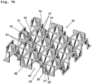
- FIG. 11A is an exploded perspective view of a multiple support wall structure A according to a sixth embodiment of the present invention, in which an intermediate inserting member 6 is disposed at the middle portion and the top and bottom support plates 1 and 1' according to the first embodiment are fixed to the top and the bottom of the intermediate inserting member 6.
- a plurality of pyramidal projective cells 60 are laterally and longitudinally sequentially formed, straight line-shaped projections 61 horizontally protruding are formed at the middle portions of the pyramidal projective cells 60, grooves 62 are formed at both ends of each of the straight line-shaped projections 61, slopes 63 are formed at both sides of the straight line-shaped projections 61, and pyramid-side walls 64 are formed at the edges of the slopes 63 and have a triangular cross section that is smaller at the top.
- pyramidal projective cells 60' which have straight line-shaped projections 61' protruding in the opposite direction and formed perpendicular to the straight line-shaped projections 61 are laterally and longitudinally sequentially formed at the joints of the pyramid-side walls 64. Accordingly, the pyramidal projective cells 60 having the straight line-shaped projections 61 are formed on a side of the intermediate inserting member 6 and the pyramidal projective cells 60' protruding in the opposite direction and having the straight line-shaped projections 61' formed perpendicular to the straight line-shaped projections 61 are laterally and longitudinally sequentially formed on the opposite side.
- the intermediate inserting member 6 is also made of synthetic resin in the same way as the intermediate reinforcing plates 2.
- the straight line-shaped projections 61 of the pyramidal projective cells 60 are in contact with the bottoms of the flat cross projections 13 of the rectangular islands 11 and the slopes 63 are in contact with the slopes 14, thereby completing the multiple support walls structure according to the sixth embodiment of the present invention of which the strength is increased by a plurality of adjacent walls.
- an intermediate inserting member 6 is disposed at the middle portion, the top and bottom support plates 1 and 1' are fixed to the top and the bottom of the intermediate inserting member 6, respectively, and flat finish plates 3 are fixed to the outer sides of the upper and lower support plates 1 and 1', respectively, so a simple and strong multiple support wall structure can be achieved.
- the strength is larger and the weight is smaller than plywood or other plates and a high insulation effect can be achieved by many spaces in the multiple structures.
- the structures can be used for vertical walls of a building requiring insulation such as a glasshouse, so they can provide high insulation effects.
- the structures can provide high soundproof or sound-blocking effects, so they can be used for not only the walls of buildings, but also for separation walls in airplanes or ships, and can be used for various other purposes.
- the structures can be directly assembled without specific post-processes, so installation time, manpower for installation, and installation costs are reduced.
- the multiple support wall structures of the present invention can be repeatedly manufactured as the same products in the field of manufacturing support wall structures, so the structures have high industrial applicability.
Landscapes
- Engineering & Computer Science (AREA)
- Architecture (AREA)
- Civil Engineering (AREA)
- Structural Engineering (AREA)
- Physics & Mathematics (AREA)
- Acoustics & Sound (AREA)
- Electromagnetism (AREA)
- Finishing Walls (AREA)
- Floor Finish (AREA)
- Laminated Bodies (AREA)
Applications Claiming Priority (2)
| Application Number | Priority Date | Filing Date | Title |
|---|---|---|---|
| KR20140167412 | 2014-11-27 | ||
| PCT/KR2015/012609 WO2016085220A1 (fr) | 2014-11-27 | 2015-11-24 | Structure de paroi à supports multiples |
Publications (3)
| Publication Number | Publication Date |
|---|---|
| EP3225760A1 true EP3225760A1 (fr) | 2017-10-04 |
| EP3225760A4 EP3225760A4 (fr) | 2018-10-17 |
| EP3225760B1 EP3225760B1 (fr) | 2019-05-22 |
Family
ID=55644984
Family Applications (1)
| Application Number | Title | Priority Date | Filing Date |
|---|---|---|---|
| EP15863278.6A Not-in-force EP3225760B1 (fr) | 2014-11-27 | 2015-11-24 | Structure de paroi à supports multiples |
Country Status (6)
| Country | Link |
|---|---|
| US (2) | US10174502B2 (fr) |
| EP (1) | EP3225760B1 (fr) |
| KR (1) | KR101605662B1 (fr) |
| CN (1) | CN106661886B (fr) |
| RU (1) | RU2661947C1 (fr) |
| WO (1) | WO2016085220A1 (fr) |
Families Citing this family (14)
| Publication number | Priority date | Publication date | Assignee | Title |
|---|---|---|---|---|
| WO2017120378A1 (fr) * | 2016-01-08 | 2017-07-13 | VICIS, Inc. | Fabrication de structures absorbant les chocs destinées à un casque de sport |
| USD848033S1 (en) * | 2017-09-06 | 2019-05-07 | The Pro Design Group, Inc. | Structural panel core |
| USD848032S1 (en) * | 2017-09-06 | 2019-05-07 | The Pro Dsign Group, Inc. | Structural panel core |
| AT520524B1 (de) * | 2017-09-12 | 2019-05-15 | Rep Ip Ag | Thermisches Isolationselement |
| US11319133B2 (en) * | 2018-02-02 | 2022-05-03 | Foldstar, Inc. | Multi-laminate folded materials for construction of boxes and other objects |
| CN108867425B (zh) * | 2018-07-25 | 2020-10-23 | 华东交通大学 | 一种隧道主动式吸振吸附式多重声屏障 |
| CN109577547A (zh) * | 2018-12-17 | 2019-04-05 | 扬州维森视觉技术有限公司 | 一种半蜂窝钣金复合夹芯板及其制作方法 |
| USD925777S1 (en) * | 2019-08-28 | 2021-07-20 | Formflow Pty Ltd | Structural panel |
| US11794927B2 (en) * | 2019-08-28 | 2023-10-24 | The Boeing Company | Additively manufactured spacecraft panel |
| US11542041B2 (en) | 2020-05-18 | 2023-01-03 | The Boeing Company | Additively manufactured satellite panel with damping |
| CN111622438B (zh) * | 2020-05-18 | 2021-08-10 | 辰航新材料科技有限公司 | 一种冲孔吸音蜂窝铝复合板 |
| US11827389B2 (en) | 2020-05-18 | 2023-11-28 | The Boeing Company | Additively manufactured satellite |
| KR102672542B1 (ko) | 2021-06-09 | 2024-06-04 | 김충기 | 3d프린터를 이용한 지지벽 구조체 |
| US20250109586A1 (en) * | 2022-01-14 | 2025-04-03 | University Of Puerto Rico | Scutoidal sub-cell and cell arrangements |
Family Cites Families (32)
| Publication number | Priority date | Publication date | Assignee | Title |
|---|---|---|---|---|
| DE1056031B (de) * | 1955-12-22 | 1959-04-23 | Karl Hertlein | Verfahren zum Herstellen schalldaemmender Gipsbauplatten |
| US3108924A (en) * | 1959-04-14 | 1963-10-29 | Adie George Mountford | Structural element |
| GB956132A (en) * | 1959-04-14 | 1964-04-22 | George Mountford Adie | Improvements in and relating to laminated slabs or panels |
| US4348442A (en) * | 1979-08-17 | 1982-09-07 | Figge Irving E | Structural panel |
| US4495237A (en) * | 1983-06-10 | 1985-01-22 | Patterson Fred R | Pyramidal core structure |
| WO1988003086A1 (fr) * | 1986-10-24 | 1988-05-05 | Patterson Fred R | Structure d'ame a geometrie variable |
| AU6733087A (en) * | 1986-10-24 | 1988-05-25 | Patterson, F.R. | Variable geometry core structure |
| US5030501A (en) * | 1989-05-31 | 1991-07-09 | Raven Marketing, Inc. | Cushioning structure |
| US5270092A (en) * | 1991-08-08 | 1993-12-14 | The Regents, University Of California | Gas filled panel insulation |
| US5543204A (en) * | 1995-01-05 | 1996-08-06 | The United States Of America As Represented By The Secretary Of The Navy | Bi-directionally corrugated sandwich construction |
| RU2081267C1 (ru) * | 1995-02-22 | 1997-06-10 | Анатолий Алексеевич Иванов | Способ изготовления сотовых заполнителей |
| JP2901959B2 (ja) * | 1997-05-21 | 1999-06-07 | 株式会社環境アセスメントセンター | 積層構造物 |
| US6003283A (en) * | 1998-05-07 | 1999-12-21 | Hexcel Corporation | Vented flexible honeycomb |
| DE10022742A1 (de) * | 1999-05-27 | 2001-06-07 | Peter Kueppers | Leichtbauelement in Form einer Hohlkörperkonturwabe |
| DK1181421T3 (da) * | 1999-05-27 | 2003-11-03 | Sparkasse Kleve | Lætvægts-byggeelement i form af en honeycombkonstruktion med hullegemekontur |
| US6713008B1 (en) * | 2000-06-23 | 2004-03-30 | Darrin Blake Teeter | Method for making composite structures |
| KR100456385B1 (ko) | 2002-01-14 | 2004-11-10 | (주)단건축사사무소 | 건축용 단열보드의 제조장치 |
| KR200273479Y1 (ko) * | 2002-01-15 | 2002-04-26 | 김무곤 | 건축용 단열보드 |
| DE10203276C2 (de) * | 2002-01-29 | 2003-12-04 | Hubert Leutermann | Leichtbaustrukturelement mit arretierendem Nut- und Federeffekt |
| US7021017B2 (en) * | 2004-03-08 | 2006-04-04 | Herron Intellectual Property Holdings, Llc | High strength low density multi-purpose panel |
| DE212004000096U1 (de) * | 2004-12-01 | 2007-07-05 | Hakemann, Fritz | Verbundplatte |
| KR200402348Y1 (ko) * | 2005-09-02 | 2005-11-29 | 권병국 | 건축용 단열 및 차음 복합패널 |
| US8381471B2 (en) * | 2005-12-09 | 2013-02-26 | Stephen C. Kobre | Packaging/construction material to make variable sized structures with intrinsic cushioning |
| US7762938B2 (en) * | 2006-07-24 | 2010-07-27 | Tessellated Group, Llc | Three-dimensional support structure |
| WO2009108712A2 (fr) * | 2008-02-26 | 2009-09-03 | Klaus Stadthagen-Gonzalez | Elément structurel |
| KR100959175B1 (ko) | 2008-04-29 | 2010-05-24 | 한국이엔에쓰 주식회사 | 일체형 거푸집 |
| WO2011011634A1 (fr) * | 2009-07-22 | 2011-01-27 | Straza George C P | Structures en sandwich à cur formé |
| DE102009056969A1 (de) * | 2009-12-07 | 2011-06-09 | Claas Selbstfahrende Erntemaschinen Gmbh | Flächiges Karosserieelement in Sandwichbauweise |
| DE102011100967A1 (de) * | 2011-05-09 | 2013-01-03 | Peter Küppers | Hohlkörperanordnung und Verfahren zur Herstellung derselben |
| RU113756U1 (ru) * | 2011-09-20 | 2012-02-27 | Федеральное государственное бюджетное образовательное учреждение высшего профессионального образования "Казанский национальный исследовательский технический университет им. А.Н. Туполева-КАИ" (КНИТУ-КАИ) | Многослойная панель |
| JP2013204719A (ja) * | 2012-03-28 | 2013-10-07 | Mitsubishi Heavy Ind Ltd | パネル構造体、及びその製造方法 |
| US9925736B2 (en) * | 2013-12-13 | 2018-03-27 | Celltech Metals, Inc. | Sandwich structure |
-
2015
- 2015-11-23 KR KR1020150164064A patent/KR101605662B1/ko active Active
- 2015-11-24 WO PCT/KR2015/012609 patent/WO2016085220A1/fr not_active Ceased
- 2015-11-24 RU RU2017106957A patent/RU2661947C1/ru not_active IP Right Cessation
- 2015-11-24 EP EP15863278.6A patent/EP3225760B1/fr not_active Not-in-force
- 2015-11-24 CN CN201580047221.7A patent/CN106661886B/zh not_active Expired - Fee Related
- 2015-11-24 US US15/507,096 patent/US10174502B2/en not_active Expired - Fee Related
-
2018
- 2018-12-04 US US16/208,704 patent/US10415246B2/en not_active Expired - Fee Related
Also Published As
| Publication number | Publication date |
|---|---|
| EP3225760B1 (fr) | 2019-05-22 |
| WO2016085220A1 (fr) | 2016-06-02 |
| CN106661886B (zh) | 2019-05-28 |
| KR101605662B1 (ko) | 2016-03-22 |
| RU2661947C1 (ru) | 2018-07-23 |
| EP3225760A4 (fr) | 2018-10-17 |
| US20190100916A1 (en) | 2019-04-04 |
| CN106661886A (zh) | 2017-05-10 |
| US20170284094A1 (en) | 2017-10-05 |
| US10174502B2 (en) | 2019-01-08 |
| US10415246B2 (en) | 2019-09-17 |
Similar Documents
| Publication | Publication Date | Title |
|---|---|---|
| US10415246B2 (en) | Multiple support wall structure | |
| US5894045A (en) | Cellular core structure building component | |
| CN100455724C (zh) | 结构板 | |
| US20150047286A1 (en) | Modular assembly for covering a floor | |
| US3234692A (en) | Tile construction | |
| KR101079252B1 (ko) | 알루미늄 패널로 된 실험테이블용 상판 | |
| EP2554756A3 (fr) | Panneau et procédé de construction de panneaux | |
| CN102312885A (zh) | 条板材拼接接头结构 | |
| CN210508196U (zh) | 装饰地板 | |
| DK3098363T3 (en) | Partition structure and method for making a partition structure | |
| CN208428780U (zh) | 一种蜂窝板 | |
| CN103608530A (zh) | 基于元件的覆盖系统 | |
| CN211231177U (zh) | 吊顶用指接板 | |
| JP4637156B2 (ja) | タイルユニットの製造方法 | |
| CA2538762A1 (fr) | Pour fabriquer une structure a nids d'abeille | |
| JP2016060171A (ja) | サンドイッチパネル用コア材、サンドイッチパネル用コアおよびサンドイッチパネル | |
| JP3122380U (ja) | 下地部材 | |
| CN221194092U (zh) | 一种快速导热型地板连接条及抗变形的地板 | |
| JP7521749B2 (ja) | 面材の施工方法およびヘリンボン貼り用の起点面材ユニット | |
| JP2001262771A (ja) | パネル用芯材及びそれを用いたパネル | |
| CN103097625B (zh) | 具有棱边保护部的模板元件和用来制造该模板元件的方法 | |
| JP5849481B2 (ja) | 型枠パネル、及びコンクリート壁体の構築構造 | |
| KR200454372Y1 (ko) | 거푸집용 목재빔 | |
| JP2020105755A (ja) | 床材 | |
| JP4576297B2 (ja) | 床下地面へ床材を敷き詰める方法 |
Legal Events
| Date | Code | Title | Description |
|---|---|---|---|
| STAA | Information on the status of an ep patent application or granted ep patent |
Free format text: STATUS: THE INTERNATIONAL PUBLICATION HAS BEEN MADE |
|
| PUAI | Public reference made under article 153(3) epc to a published international application that has entered the european phase |
Free format text: ORIGINAL CODE: 0009012 |
|
| STAA | Information on the status of an ep patent application or granted ep patent |
Free format text: STATUS: REQUEST FOR EXAMINATION WAS MADE |
|
| 17P | Request for examination filed |
Effective date: 20170323 |
|
| AK | Designated contracting states |
Kind code of ref document: A1 Designated state(s): AL AT BE BG CH CY CZ DE DK EE ES FI FR GB GR HR HU IE IS IT LI LT LU LV MC MK MT NL NO PL PT RO RS SE SI SK SM TR |
|
| AX | Request for extension of the european patent |
Extension state: BA ME |
|
| DAV | Request for validation of the european patent (deleted) | ||
| DAX | Request for extension of the european patent (deleted) | ||
| A4 | Supplementary search report drawn up and despatched |
Effective date: 20180919 |
|
| RIC1 | Information provided on ipc code assigned before grant |
Ipc: E04B 1/90 20060101AFI20180913BHEP Ipc: E04C 2/32 20060101ALI20180913BHEP |
|
| GRAP | Despatch of communication of intention to grant a patent |
Free format text: ORIGINAL CODE: EPIDOSNIGR1 |
|
| STAA | Information on the status of an ep patent application or granted ep patent |
Free format text: STATUS: GRANT OF PATENT IS INTENDED |
|
| INTG | Intention to grant announced |
Effective date: 20181205 |
|
| GRAS | Grant fee paid |
Free format text: ORIGINAL CODE: EPIDOSNIGR3 |
|
| GRAA | (expected) grant |
Free format text: ORIGINAL CODE: 0009210 |
|
| STAA | Information on the status of an ep patent application or granted ep patent |
Free format text: STATUS: THE PATENT HAS BEEN GRANTED |
|
| AK | Designated contracting states |
Kind code of ref document: B1 Designated state(s): AL AT BE BG CH CY CZ DE DK EE ES FI FR GB GR HR HU IE IS IT LI LT LU LV MC MK MT NL NO PL PT RO RS SE SI SK SM TR |
|
| REG | Reference to a national code |
Ref country code: GB Ref legal event code: FG4D |
|
| REG | Reference to a national code |
Ref country code: CH Ref legal event code: EP |
|
| REG | Reference to a national code |
Ref country code: IE Ref legal event code: FG4D |
|
| REG | Reference to a national code |
Ref country code: AT Ref legal event code: REF Ref document number: 1136282 Country of ref document: AT Kind code of ref document: T Effective date: 20190615 |
|
| REG | Reference to a national code |
Ref country code: DE Ref legal event code: R096 Ref document number: 602015030982 Country of ref document: DE |
|
| REG | Reference to a national code |
Ref country code: NL Ref legal event code: MP Effective date: 20190522 |
|
| REG | Reference to a national code |
Ref country code: LT Ref legal event code: MG4D |
|
| PG25 | Lapsed in a contracting state [announced via postgrant information from national office to epo] |
Ref country code: FI Free format text: LAPSE BECAUSE OF FAILURE TO SUBMIT A TRANSLATION OF THE DESCRIPTION OR TO PAY THE FEE WITHIN THE PRESCRIBED TIME-LIMIT Effective date: 20190522 Ref country code: PT Free format text: LAPSE BECAUSE OF FAILURE TO SUBMIT A TRANSLATION OF THE DESCRIPTION OR TO PAY THE FEE WITHIN THE PRESCRIBED TIME-LIMIT Effective date: 20190922 Ref country code: AL Free format text: LAPSE BECAUSE OF FAILURE TO SUBMIT A TRANSLATION OF THE DESCRIPTION OR TO PAY THE FEE WITHIN THE PRESCRIBED TIME-LIMIT Effective date: 20190522 Ref country code: SE Free format text: LAPSE BECAUSE OF FAILURE TO SUBMIT A TRANSLATION OF THE DESCRIPTION OR TO PAY THE FEE WITHIN THE PRESCRIBED TIME-LIMIT Effective date: 20190522 Ref country code: NO Free format text: LAPSE BECAUSE OF FAILURE TO SUBMIT A TRANSLATION OF THE DESCRIPTION OR TO PAY THE FEE WITHIN THE PRESCRIBED TIME-LIMIT Effective date: 20190822 Ref country code: HR Free format text: LAPSE BECAUSE OF FAILURE TO SUBMIT A TRANSLATION OF THE DESCRIPTION OR TO PAY THE FEE WITHIN THE PRESCRIBED TIME-LIMIT Effective date: 20190522 Ref country code: NL Free format text: LAPSE BECAUSE OF FAILURE TO SUBMIT A TRANSLATION OF THE DESCRIPTION OR TO PAY THE FEE WITHIN THE PRESCRIBED TIME-LIMIT Effective date: 20190522 Ref country code: LT Free format text: LAPSE BECAUSE OF FAILURE TO SUBMIT A TRANSLATION OF THE DESCRIPTION OR TO PAY THE FEE WITHIN THE PRESCRIBED TIME-LIMIT Effective date: 20190522 |
|
| PG25 | Lapsed in a contracting state [announced via postgrant information from national office to epo] |
Ref country code: LV Free format text: LAPSE BECAUSE OF FAILURE TO SUBMIT A TRANSLATION OF THE DESCRIPTION OR TO PAY THE FEE WITHIN THE PRESCRIBED TIME-LIMIT Effective date: 20190522 Ref country code: RS Free format text: LAPSE BECAUSE OF FAILURE TO SUBMIT A TRANSLATION OF THE DESCRIPTION OR TO PAY THE FEE WITHIN THE PRESCRIBED TIME-LIMIT Effective date: 20190522 Ref country code: BG Free format text: LAPSE BECAUSE OF FAILURE TO SUBMIT A TRANSLATION OF THE DESCRIPTION OR TO PAY THE FEE WITHIN THE PRESCRIBED TIME-LIMIT Effective date: 20190822 Ref country code: GR Free format text: LAPSE BECAUSE OF FAILURE TO SUBMIT A TRANSLATION OF THE DESCRIPTION OR TO PAY THE FEE WITHIN THE PRESCRIBED TIME-LIMIT Effective date: 20190823 |
|
| REG | Reference to a national code |
Ref country code: AT Ref legal event code: MK05 Ref document number: 1136282 Country of ref document: AT Kind code of ref document: T Effective date: 20190522 |
|
| PG25 | Lapsed in a contracting state [announced via postgrant information from national office to epo] |
Ref country code: SK Free format text: LAPSE BECAUSE OF FAILURE TO SUBMIT A TRANSLATION OF THE DESCRIPTION OR TO PAY THE FEE WITHIN THE PRESCRIBED TIME-LIMIT Effective date: 20190522 Ref country code: DK Free format text: LAPSE BECAUSE OF FAILURE TO SUBMIT A TRANSLATION OF THE DESCRIPTION OR TO PAY THE FEE WITHIN THE PRESCRIBED TIME-LIMIT Effective date: 20190522 Ref country code: AT Free format text: LAPSE BECAUSE OF FAILURE TO SUBMIT A TRANSLATION OF THE DESCRIPTION OR TO PAY THE FEE WITHIN THE PRESCRIBED TIME-LIMIT Effective date: 20190522 Ref country code: EE Free format text: LAPSE BECAUSE OF FAILURE TO SUBMIT A TRANSLATION OF THE DESCRIPTION OR TO PAY THE FEE WITHIN THE PRESCRIBED TIME-LIMIT Effective date: 20190522 Ref country code: RO Free format text: LAPSE BECAUSE OF FAILURE TO SUBMIT A TRANSLATION OF THE DESCRIPTION OR TO PAY THE FEE WITHIN THE PRESCRIBED TIME-LIMIT Effective date: 20190522 Ref country code: CZ Free format text: LAPSE BECAUSE OF FAILURE TO SUBMIT A TRANSLATION OF THE DESCRIPTION OR TO PAY THE FEE WITHIN THE PRESCRIBED TIME-LIMIT Effective date: 20190522 |
|
| PGFP | Annual fee paid to national office [announced via postgrant information from national office to epo] |
Ref country code: DE Payment date: 20191127 Year of fee payment: 5 |
|
| REG | Reference to a national code |
Ref country code: DE Ref legal event code: R097 Ref document number: 602015030982 Country of ref document: DE |
|
| PG25 | Lapsed in a contracting state [announced via postgrant information from national office to epo] |
Ref country code: SM Free format text: LAPSE BECAUSE OF FAILURE TO SUBMIT A TRANSLATION OF THE DESCRIPTION OR TO PAY THE FEE WITHIN THE PRESCRIBED TIME-LIMIT Effective date: 20190522 Ref country code: IT Free format text: LAPSE BECAUSE OF FAILURE TO SUBMIT A TRANSLATION OF THE DESCRIPTION OR TO PAY THE FEE WITHIN THE PRESCRIBED TIME-LIMIT Effective date: 20190522 |
|
| PGFP | Annual fee paid to national office [announced via postgrant information from national office to epo] |
Ref country code: FR Payment date: 20191122 Year of fee payment: 5 |
|
| PLBE | No opposition filed within time limit |
Free format text: ORIGINAL CODE: 0009261 |
|
| STAA | Information on the status of an ep patent application or granted ep patent |
Free format text: STATUS: NO OPPOSITION FILED WITHIN TIME LIMIT |
|
| PG25 | Lapsed in a contracting state [announced via postgrant information from national office to epo] |
Ref country code: TR Free format text: LAPSE BECAUSE OF FAILURE TO SUBMIT A TRANSLATION OF THE DESCRIPTION OR TO PAY THE FEE WITHIN THE PRESCRIBED TIME-LIMIT Effective date: 20190522 |
|
| 26N | No opposition filed |
Effective date: 20200225 |
|
| PG25 | Lapsed in a contracting state [announced via postgrant information from national office to epo] |
Ref country code: PL Free format text: LAPSE BECAUSE OF FAILURE TO SUBMIT A TRANSLATION OF THE DESCRIPTION OR TO PAY THE FEE WITHIN THE PRESCRIBED TIME-LIMIT Effective date: 20190522 |
|
| PGFP | Annual fee paid to national office [announced via postgrant information from national office to epo] |
Ref country code: GB Payment date: 20191122 Year of fee payment: 5 |
|
| PG25 | Lapsed in a contracting state [announced via postgrant information from national office to epo] |
Ref country code: SI Free format text: LAPSE BECAUSE OF FAILURE TO SUBMIT A TRANSLATION OF THE DESCRIPTION OR TO PAY THE FEE WITHIN THE PRESCRIBED TIME-LIMIT Effective date: 20190522 |
|
| REG | Reference to a national code |
Ref country code: CH Ref legal event code: PL |
|
| PG25 | Lapsed in a contracting state [announced via postgrant information from national office to epo] |
Ref country code: LU Free format text: LAPSE BECAUSE OF NON-PAYMENT OF DUE FEES Effective date: 20191124 Ref country code: CH Free format text: LAPSE BECAUSE OF NON-PAYMENT OF DUE FEES Effective date: 20191130 Ref country code: MC Free format text: LAPSE BECAUSE OF FAILURE TO SUBMIT A TRANSLATION OF THE DESCRIPTION OR TO PAY THE FEE WITHIN THE PRESCRIBED TIME-LIMIT Effective date: 20190522 Ref country code: LI Free format text: LAPSE BECAUSE OF NON-PAYMENT OF DUE FEES Effective date: 20191130 |
|
| REG | Reference to a national code |
Ref country code: BE Ref legal event code: MM Effective date: 20191130 |
|
| PG25 | Lapsed in a contracting state [announced via postgrant information from national office to epo] |
Ref country code: IE Free format text: LAPSE BECAUSE OF NON-PAYMENT OF DUE FEES Effective date: 20191124 Ref country code: ES Free format text: LAPSE BECAUSE OF FAILURE TO SUBMIT A TRANSLATION OF THE DESCRIPTION OR TO PAY THE FEE WITHIN THE PRESCRIBED TIME-LIMIT Effective date: 20190522 |
|
| PG25 | Lapsed in a contracting state [announced via postgrant information from national office to epo] |
Ref country code: BE Free format text: LAPSE BECAUSE OF NON-PAYMENT OF DUE FEES Effective date: 20191130 |
|
| PG25 | Lapsed in a contracting state [announced via postgrant information from national office to epo] |
Ref country code: CY Free format text: LAPSE BECAUSE OF FAILURE TO SUBMIT A TRANSLATION OF THE DESCRIPTION OR TO PAY THE FEE WITHIN THE PRESCRIBED TIME-LIMIT Effective date: 20190522 |
|
| REG | Reference to a national code |
Ref country code: DE Ref legal event code: R119 Ref document number: 602015030982 Country of ref document: DE |
|
| PG25 | Lapsed in a contracting state [announced via postgrant information from national office to epo] |
Ref country code: IS Free format text: LAPSE BECAUSE OF FAILURE TO SUBMIT A TRANSLATION OF THE DESCRIPTION OR TO PAY THE FEE WITHIN THE PRESCRIBED TIME-LIMIT Effective date: 20190922 |
|
| GBPC | Gb: european patent ceased through non-payment of renewal fee |
Effective date: 20201124 |
|
| PG25 | Lapsed in a contracting state [announced via postgrant information from national office to epo] |
Ref country code: HU Free format text: LAPSE BECAUSE OF FAILURE TO SUBMIT A TRANSLATION OF THE DESCRIPTION OR TO PAY THE FEE WITHIN THE PRESCRIBED TIME-LIMIT; INVALID AB INITIO Effective date: 20151124 Ref country code: MT Free format text: LAPSE BECAUSE OF FAILURE TO SUBMIT A TRANSLATION OF THE DESCRIPTION OR TO PAY THE FEE WITHIN THE PRESCRIBED TIME-LIMIT Effective date: 20190522 |
|
| PG25 | Lapsed in a contracting state [announced via postgrant information from national office to epo] |
Ref country code: FR Free format text: LAPSE BECAUSE OF NON-PAYMENT OF DUE FEES Effective date: 20201130 |
|
| PG25 | Lapsed in a contracting state [announced via postgrant information from national office to epo] |
Ref country code: GB Free format text: LAPSE BECAUSE OF NON-PAYMENT OF DUE FEES Effective date: 20201124 Ref country code: DE Free format text: LAPSE BECAUSE OF NON-PAYMENT OF DUE FEES Effective date: 20210601 |
|
| PG25 | Lapsed in a contracting state [announced via postgrant information from national office to epo] |
Ref country code: MK Free format text: LAPSE BECAUSE OF FAILURE TO SUBMIT A TRANSLATION OF THE DESCRIPTION OR TO PAY THE FEE WITHIN THE PRESCRIBED TIME-LIMIT Effective date: 20190522 |