EP3225788B1 - Aktives deckband für gasturbine - Google Patents
Aktives deckband für gasturbine Download PDFInfo
- Publication number
- EP3225788B1 EP3225788B1 EP17154287.1A EP17154287A EP3225788B1 EP 3225788 B1 EP3225788 B1 EP 3225788B1 EP 17154287 A EP17154287 A EP 17154287A EP 3225788 B1 EP3225788 B1 EP 3225788B1
- Authority
- EP
- European Patent Office
- Prior art keywords
- case
- engine case
- cooling
- engine
- region
- Prior art date
- Legal status (The legal status is an assumption and is not a legal conclusion. Google has not performed a legal analysis and makes no representation as to the accuracy of the status listed.)
- Active
Links
Images




Classifications
-
- F—MECHANICAL ENGINEERING; LIGHTING; HEATING; WEAPONS; BLASTING
- F01—MACHINES OR ENGINES IN GENERAL; ENGINE PLANTS IN GENERAL; STEAM ENGINES
- F01D—NON-POSITIVE DISPLACEMENT MACHINES OR ENGINES, e.g. STEAM TURBINES
- F01D25/00—Component parts, details, or accessories, not provided for in, or of interest apart from, other groups
- F01D25/24—Casings; Casing parts, e.g. diaphragms, casing fastenings
-
- F—MECHANICAL ENGINEERING; LIGHTING; HEATING; WEAPONS; BLASTING
- F01—MACHINES OR ENGINES IN GENERAL; ENGINE PLANTS IN GENERAL; STEAM ENGINES
- F01D—NON-POSITIVE DISPLACEMENT MACHINES OR ENGINES, e.g. STEAM TURBINES
- F01D11/00—Preventing or minimising internal leakage of working-fluid, e.g. between stages
- F01D11/08—Preventing or minimising internal leakage of working-fluid, e.g. between stages for sealing space between rotor blade tips and stator
- F01D11/14—Adjusting or regulating tip-clearance, i.e. distance between rotor-blade tips and stator casing
- F01D11/20—Actively adjusting tip-clearance
- F01D11/24—Actively adjusting tip-clearance by selectively cooling-heating stator or rotor components
-
- F—MECHANICAL ENGINEERING; LIGHTING; HEATING; WEAPONS; BLASTING
- F01—MACHINES OR ENGINES IN GENERAL; ENGINE PLANTS IN GENERAL; STEAM ENGINES
- F01D—NON-POSITIVE DISPLACEMENT MACHINES OR ENGINES, e.g. STEAM TURBINES
- F01D25/00—Component parts, details, or accessories, not provided for in, or of interest apart from, other groups
- F01D25/08—Cooling; Heating; Heat-insulation
- F01D25/14—Casings modified therefor
-
- F—MECHANICAL ENGINEERING; LIGHTING; HEATING; WEAPONS; BLASTING
- F01—MACHINES OR ENGINES IN GENERAL; ENGINE PLANTS IN GENERAL; STEAM ENGINES
- F01D—NON-POSITIVE DISPLACEMENT MACHINES OR ENGINES, e.g. STEAM TURBINES
- F01D21/00—Shutting-down of machines or engines, e.g. in emergency; Regulating, controlling, or safety means not otherwise provided for
- F01D21/04—Shutting-down of machines or engines, e.g. in emergency; Regulating, controlling, or safety means not otherwise provided for responsive to undesired position of rotor relative to stator or to breaking-off of a part of the rotor, e.g. indicating such position
- F01D21/045—Shutting-down of machines or engines, e.g. in emergency; Regulating, controlling, or safety means not otherwise provided for responsive to undesired position of rotor relative to stator or to breaking-off of a part of the rotor, e.g. indicating such position special arrangements in stators or in rotors dealing with breaking-off of part of rotor
-
- F—MECHANICAL ENGINEERING; LIGHTING; HEATING; WEAPONS; BLASTING
- F01—MACHINES OR ENGINES IN GENERAL; ENGINE PLANTS IN GENERAL; STEAM ENGINES
- F01D—NON-POSITIVE DISPLACEMENT MACHINES OR ENGINES, e.g. STEAM TURBINES
- F01D25/00—Component parts, details, or accessories, not provided for in, or of interest apart from, other groups
- F01D25/08—Cooling; Heating; Heat-insulation
- F01D25/12—Cooling
-
- F—MECHANICAL ENGINEERING; LIGHTING; HEATING; WEAPONS; BLASTING
- F02—COMBUSTION ENGINES; HOT-GAS OR COMBUSTION-PRODUCT ENGINE PLANTS
- F02C—GAS-TURBINE PLANTS; AIR INTAKES FOR JET-PROPULSION PLANTS; CONTROLLING FUEL SUPPLY IN AIR-BREATHING JET-PROPULSION PLANTS
- F02C3/00—Gas-turbine plants characterised by the use of combustion products as the working fluid
- F02C3/04—Gas-turbine plants characterised by the use of combustion products as the working fluid having a turbine driving a compressor
-
- F—MECHANICAL ENGINEERING; LIGHTING; HEATING; WEAPONS; BLASTING
- F05—INDEXING SCHEMES RELATING TO ENGINES OR PUMPS IN VARIOUS SUBCLASSES OF CLASSES F01-F04
- F05D—INDEXING SCHEME FOR ASPECTS RELATING TO NON-POSITIVE-DISPLACEMENT MACHINES OR ENGINES, GAS-TURBINES OR JET-PROPULSION PLANTS
- F05D2220/00—Application
- F05D2220/30—Application in turbines
- F05D2220/32—Application in turbines in gas turbines
- F05D2220/323—Application in turbines in gas turbines for aircraft propulsion, e.g. jet engines
-
- F—MECHANICAL ENGINEERING; LIGHTING; HEATING; WEAPONS; BLASTING
- F05—INDEXING SCHEMES RELATING TO ENGINES OR PUMPS IN VARIOUS SUBCLASSES OF CLASSES F01-F04
- F05D—INDEXING SCHEME FOR ASPECTS RELATING TO NON-POSITIVE-DISPLACEMENT MACHINES OR ENGINES, GAS-TURBINES OR JET-PROPULSION PLANTS
- F05D2240/00—Components
- F05D2240/10—Stators
- F05D2240/11—Shroud seal segments
-
- F—MECHANICAL ENGINEERING; LIGHTING; HEATING; WEAPONS; BLASTING
- F05—INDEXING SCHEMES RELATING TO ENGINES OR PUMPS IN VARIOUS SUBCLASSES OF CLASSES F01-F04
- F05D—INDEXING SCHEME FOR ASPECTS RELATING TO NON-POSITIVE-DISPLACEMENT MACHINES OR ENGINES, GAS-TURBINES OR JET-PROPULSION PLANTS
- F05D2240/00—Components
- F05D2240/10—Stators
- F05D2240/14—Casings or housings protecting or supporting assemblies within
-
- F—MECHANICAL ENGINEERING; LIGHTING; HEATING; WEAPONS; BLASTING
- F05—INDEXING SCHEMES RELATING TO ENGINES OR PUMPS IN VARIOUS SUBCLASSES OF CLASSES F01-F04
- F05D—INDEXING SCHEME FOR ASPECTS RELATING TO NON-POSITIVE-DISPLACEMENT MACHINES OR ENGINES, GAS-TURBINES OR JET-PROPULSION PLANTS
- F05D2250/00—Geometry
- F05D2250/20—Three-dimensional
- F05D2250/28—Three-dimensional patterned
- F05D2250/283—Three-dimensional patterned honeycomb
-
- F—MECHANICAL ENGINEERING; LIGHTING; HEATING; WEAPONS; BLASTING
- F05—INDEXING SCHEMES RELATING TO ENGINES OR PUMPS IN VARIOUS SUBCLASSES OF CLASSES F01-F04
- F05D—INDEXING SCHEME FOR ASPECTS RELATING TO NON-POSITIVE-DISPLACEMENT MACHINES OR ENGINES, GAS-TURBINES OR JET-PROPULSION PLANTS
- F05D2260/00—Function
- F05D2260/20—Heat transfer, e.g. cooling
-
- F—MECHANICAL ENGINEERING; LIGHTING; HEATING; WEAPONS; BLASTING
- F05—INDEXING SCHEMES RELATING TO ENGINES OR PUMPS IN VARIOUS SUBCLASSES OF CLASSES F01-F04
- F05D—INDEXING SCHEME FOR ASPECTS RELATING TO NON-POSITIVE-DISPLACEMENT MACHINES OR ENGINES, GAS-TURBINES OR JET-PROPULSION PLANTS
- F05D2260/00—Function
- F05D2260/20—Heat transfer, e.g. cooling
- F05D2260/204—Heat transfer, e.g. cooling by the use of microcircuits
-
- Y—GENERAL TAGGING OF NEW TECHNOLOGICAL DEVELOPMENTS; GENERAL TAGGING OF CROSS-SECTIONAL TECHNOLOGIES SPANNING OVER SEVERAL SECTIONS OF THE IPC; TECHNICAL SUBJECTS COVERED BY FORMER USPC CROSS-REFERENCE ART COLLECTIONS [XRACs] AND DIGESTS
- Y02—TECHNOLOGIES OR APPLICATIONS FOR MITIGATION OR ADAPTATION AGAINST CLIMATE CHANGE
- Y02T—CLIMATE CHANGE MITIGATION TECHNOLOGIES RELATED TO TRANSPORTATION
- Y02T50/00—Aeronautics or air transport
- Y02T50/60—Efficient propulsion technologies, e.g. for aircraft
Definitions
- This invention relates to improved designs for engine components that include internal cooling passages formed in a sandwich structure within an engine casing.
- the invention provides structure optimized to provide for one or more of the following characteristics: structural integrity, thermo-mechanical load carrying capability, buckling, containment, cooling flow pressure drop, improved temperature gradient and finally improved life of component.
- Gas turbine engines include several sections that include rotating blades contained within the engine housing. If a rotating blade breaks it must be contained within the engine housing. To ensure broken blades do not puncture the housing, the walls of the housing have been manufactured to be relatively thick and/or reinforced with fiber fabric. Proposals to reduce weight and strengthen the LPT case have relied on additive manufacturing techniques to prepare a sandwich structure for the case with an intermediate layer that is a porous structure and/or honeycomb structure. See U.S. Pat. Appl'n. Pub. No. 2014/0161601 . These designs provide an internal porous or honeycomb structure between the inner and outer walls of an engine casing, which is designed to increase strength while reducing the weight of the engine casing. These designs rely on external piping to cool the composite engine casing.
- ACC active clearance control
- external pipes 101 supply cooling air to the outside of the engine case.
- This type of cooling system is typical in the low pressure turbine (LPT) section of a jet aircraft engine.
- the external cooling pipes 101 direct air from a manifold 202 to help maintain proper temperature of the engine casing and provide proper rotor/case clearance during operation.
- the complexity of the external piping 101, 102 and ancillary piping tubes, brackets and valve, increases manufacturing costs and increases the engine's weight.
- EP 2 977 679 A1 discloses gas turbine engine combustors, and more particularly vascular walls of the combustor and method of acoustic dampening.
- US 2012/0237786 A1 discloses walls with porous elements for component cooling, particularly in turbine engines.
- the present invention relates to improved engine components as defined in the appended Claims.
- the first and second solid wall regions make up 20% ⁇ 10% of the thickness of the engine component
- the internal cavity makes up 60% ⁇ 20% of the thickness of the engine component.
- the engine component may be the case of a low pressure turbine section of a jet aircraft engine.
- the invention allows providing cooling air from an active clearance control system and/or secondary air system within the internal region of the engine case.
- the lattice structure provided within the internal cavity can be designed to provide a desired pressure drop in a particular portion of the engine case.
- LPT low pressure turbine
- the present invention may be implemented in other engine parts for case cooling such as high pressure turbine (HPT), the high pressure compressor (HPC), turbine center frame (TCF), and combustor.
- HPT high pressure turbine
- HPC high pressure compressor
- TCF turbine center frame
- combustor combustor
- the description should clearly enable one of ordinary skill in the art to make and use the internal cooling passages, and the description sets forth several embodiment, adaptations, variations, alternatives, and uses of the internal cooling passages, including what is presently believed to be the best mode thereof.
- the internal cooling passages are described herein as being applied to a few preferred embodiments, namely to different embodiments of the internal cooling passages for an LPT engine case.
- the internal cooling passages and method of fabricating the internal cooling passages may have general application in a broad range of systems and/or a variety of commercial, industrial, and/or consumer applications other than the internal cooling passages for a LPT case of a turbine engine.
- the internal cooling passages are manufactured through additive technology with sandwich structure to reduce weight keeping the same load carrying capabilities as in existing configuration.
- the thickness of an existing engine case can be divided into two outer sections and an inner section.
- the general design is to place one or more internal cooling flowpaths 301 within the LPT case 300 of an engine.
- the internal cooling flowpath 301 occupies approximately 60% of the thickness of the case, where the remaining 40% of thickness is split among the wall of the case 300 on each side of the internal flow path 301.
- the relative thickness of the flowpath to the case can be modified to accomplish specific objectives and may also be varied along the length of the engine casing as discussed in connection with Fig. 10 .
- the internal cooling passage is provided with lattice structures that contribute to the engine casing's strength while allowing sufficient air passage (and correspondingly low pressure drop) to enable cooling air to flow through the engine case.
- the amount of blockage can vary from 20% to 80%, more preferably from 40% to 60%, and most preferably about 50%.
- the engine case wall 402 facing inward toward the turbine blade may make up 35% of the thickness of the case, whereas the outer wall 403 may make up 5% of the thickness of the case, leaving 60% of the engine case thickness for the internal coolant flowpath.
- the inner wall 502 may make up 5% of the case thickness, while the outer wall 503 makes up 35% of the thickness of the case. Again, 60% of the case thickness is reserved for internal cooling passages. See Fig. 5 .
- the inner wall 602 and outer wall 602 can each be designed to make up 10% of the thickness of the case leaving 80% of the case thickness for the internal cooling flow path 601. See Fig. 6 .
- Fig. 7 shows a cross section of a portion of the low pressure turbine casing including an annular LPT case 700 having an inner wall 702 and outer wall 703, and an internal cooling passage 701.
- the inner cooling passage 701 may be extended throughout the case 700, and if desired into the forward hook region 704 that engages with the forward lip 705 of the shroud 706.
- the present invention may be integrated into an engine casing having passages 707 that allow for air flow between the case 700 and the shroud 706.
- the internal cooling path is provided within the engine case 700 along axis B-B.
- the flow within the lattice structure may be used to purge/seal the vane-hook region 704 of the flow path.
- the internal cooling passage 701 includes structures that can have varying orientations relative to the cooling air flow.
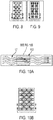
- Fig. 8 shows structures that are aligned with the cooling flow
- Fig. 9 shows structures that oppose the cooling flow.
- Fig. 10 is a top view of the cooling flow through different types of lattice structure.
- the lattice structure is designed to limit flow and provide enhanced structural support to the case, which increases pressure drop through this region.
- the increased pressure drop may also result from the lattice orientation that restricts flow as shown in Fig. 9 .
- the pressure drop is reduced due to the use of a lattice structure that promotes flow ( Fig. 8 ).
- An increase in the relative thickness of the internal coolant flow path as described in connection with Fig. 6 may also be used to provide a lower pressure drop.
- the different lattice designs allow for optimizing the porosity and strength of the structural components provided within the internal cooling path.
- the different lattice types can be any type of desired grid, high-stiffhess grid, honeycomb, or sphere-based topology.
- the grid patterns can be provided using Autodesk® within product described at http://www.withinlab.com/case-studies/new_index10.php.
- the lattice design can match the external surface of the case while providing hollow interiors for lattices or voids.
- the internal lattices provide an internal support structure to carry structural and thermal loads. Because the engine case is prepared using additive manufacturing techniques, the specific structure utilized within the internal cooling path can be any desired pattern. By arranging lattice structures within the internal cavity, the need for structural rigidity of the case can be balanced against the desired pressure drop within the coolant cavity.
- the interior cavity of the engine case is divided into two or more distinct coolant channels as shown in Fig. 11 .
- bypass air for cooling 1101 can be routed into a first internal cavity, and higher pressure secondary air system (SAS) air 1102 can be routed into the second cavity.
- SAS secondary air system
- the use of secondary air system (SAS) for cooling is minimized.
- the lattice structure is optimized to pass cooling flow for the case cooling and maintaining rotor/case clearances.
- the active clearance control (ACC) cooling flow is routed in between two layers along lattice structure to control LPT tip clearance, thus replacing existing solid case with external ACC pipe arrangement.
- the external pipes used to cool the solid case in a LPT engine are partially or entirely replaced through the use of internal cooling passages in the case.
- the ACC cooling flow may be combined with higher pressure air from the secondary air system (SAS) in order to achieve the cooling and clearance objectives of the system.
- SAS secondary air system
- the particular coolant path and lattice structure are designed to account for the pressure drop in the system and to optimize the SAS.
- the ACC cooling flow is routed through plane 1101 and the SAS flow is routed through plane 1102 as shown in Fig. 11 .
- the ACC flow is used to optimize blade clearance and case temperature
- the SAS flow is used to purge/seal the vane-hook region 704 of the flow path as shown in Fig. 7 .
- the cooling air is introduced to the LPT case near the center of the case at cooling duct 1201 as shown in Fig. 12 .
- the cooling air then travels toward each along the axial direction of the case through the case's internal cooling path and exits at the front 1202 and rear 1203 of the case.
- Fig. 13 which is a front view along the axial direction of the case, the cooling air is introduced at three cooling duct locations 1201, 1204 and 1205, and a portion of the cooling air travels toward the front of the case and is exhausted at region 1202.
- the cooling scheme illustrated in Figs. 12-13 is advantageous in reducing the pressure drop and minimizing the amount of cooling air supply lines attached to the engine case. Other arrangements are possible.
- Fig. 12-13 is advantageous in reducing the pressure drop and minimizing the amount of cooling air supply lines attached to the engine case. Other arrangements are possible.
- the cooling supply duct 1401 is placed at the rear end of the case and cooling air travels the entire length of the case and exhausted at the front of the case 1402.
- the pressure drop across the case is higher than the embodiment shown in Figs. 12-13 .
- Fig. 15 three separate cooling ducts 1501, 1502, and 1503 are used and the cooling air is exhausted at regions 1502, 1504, and 1506. This embodiment provides for lower pressure drop but requires additional ducting around the engine case.
- the parts having integrated cooling may be manufactured according to an additive printing technique, including selective laser sintering (SLS), direct metal laser sintering (DMLS) and three dimensional printing (3DP).
- SLS selective laser sintering
- DMLS direct metal laser sintering
- 3DP three dimensional printing
- the materials can include stainless steel, aluminum, titanium, Inconel 625, Inconel 718, cobalt chrome, among other metal materials.
- powdered material is melted or sintered to form each part layer.
- the additive manufacture of large parts having integrated cooling can be accomplished using an apparatus and method such as described in U.S. Patent Application No. 14/744,982 filed June 19, 2015 , entitled "Additive Manufacturing Apparatus and Method for Large Components.” Any of the above techniques may be utilized to form the parts having integrated cooling of the present invention.
- LPT low pressure turbine
Landscapes
- Engineering & Computer Science (AREA)
- Mechanical Engineering (AREA)
- General Engineering & Computer Science (AREA)
- Turbine Rotor Nozzle Sealing (AREA)
- Sealing Using Fluids, Sealing Without Contact, And Removal Of Oil (AREA)
Claims (7)
- Triebwerksgehäuse (700) für ein Niederdruckturbinentriebwerk oder ein Hochdruckturbinentriebwerk, umfassend:einen ringförmigen Abschnitt, wobei der ringförmige Abschnitt einen ersten Vollwandbereich (402) und einen zweiten Vollwandbereich (403) umfasst;einen Innenbereich (401) zwischen dem ersten und dem zweiten Vollwandbereich (402, 403), wobei der Innenbereich (401) mindestens einen Hohlraum definiert und der Hohlraum eine Vielzahl von Strömungswegen oder -kanälen umfasst, die mit einer oder mehreren Gitterstrukturen versehen sind, die die Kühlluft-Strömung durch den Bereich steuern, dadurch gekennzeichnet, dass die eine oder die mehreren Gitterstrukturen so optimiert sind, um eine Kühlströmung für die Gehäusekühlung und zum Erreichen der Kühl-und Spaltziele des Rotorgehäuses zu leiten, worin die eine oder die mehreren Gitterstrukturen unterschiedliche Druckabfälle in der Kühlluft-Strömung erzeugen,worin eine Zunahme der relativen Dicke mindestens eines Strömungsweges zum Triebwerksgehäuse (700) entlang der Länge des Triebwerksgehäuses (700) für einen geringeren Druckabfall sorgt.
- Triebwerksgehäuse nach Anspruch 1, worin die ersten und zweiten Vollwandbereiche (402, 403) 20 % ± 10 % der Dicke des Triebwerksgehäuses ausmachen und der innere Hohlraum 60 % ± 20 % der Dicke des Triebwerksgehäuses ausmacht.
- Triebwerksgehäuse gemäß einem der vorhergehenden Ansprüche, worin das Triebwerksgehäuse so gestaltet ist, dass Kühlluft von einem aktiven Spaltregelungssystem innerhalb des Innenbereichs zugeführt wird.
- Triebwerksgehäuse gemäß einem der vorhergehenden Ansprüche, worin das Triebwerksgehäuse so gestaltet ist, im Innenbereich Kühlluft aus einem Sekundärluftsystem zugeführt wird.
- Triebwerksgehäuse gemäß einem der vorhergehenden Ansprüche, worin der Innenbereich mindestens eine erste Kühlzone und eine zweite Kühlzone umfasst.
- Triebwerksgehäuse nach Anspruch 5, worin das Triebwerksgehäuse so gestaltet ist, dass Kühlluft von einem aktiven Spaltregelungssystem innerhalb der ersten Kühlzone zugeführt wird, und das Triebwerksgehäuse so gestaltet ist, dass Kühlluft von einem Sekundärluftsystem innerhalb der zweiten Kühlzone zugeführt wird.
- Triebwerksgehäuse nach einem der vorhergehenden Ansprüche, worin die eine oder mehrere Gitterstrukturen so gestaltet sind, dass sie das Triebwerksgehäuse strukturell stützen und für einen gewünschten Druckabfall über den Hohlraum sorgen.
Applications Claiming Priority (1)
| Application Number | Priority Date | Filing Date | Title |
|---|---|---|---|
| US15/016,053 US10830097B2 (en) | 2016-02-04 | 2016-02-04 | Engine casing with internal coolant flow patterns |
Publications (3)
| Publication Number | Publication Date |
|---|---|
| EP3225788A2 EP3225788A2 (de) | 2017-10-04 |
| EP3225788A3 EP3225788A3 (de) | 2017-11-15 |
| EP3225788B1 true EP3225788B1 (de) | 2020-11-25 |
Family
ID=57960315
Family Applications (1)
| Application Number | Title | Priority Date | Filing Date |
|---|---|---|---|
| EP17154287.1A Active EP3225788B1 (de) | 2016-02-04 | 2017-02-02 | Aktives deckband für gasturbine |
Country Status (5)
| Country | Link |
|---|---|
| US (1) | US10830097B2 (de) |
| EP (1) | EP3225788B1 (de) |
| JP (2) | JP2017137865A (de) |
| CN (1) | CN107035442B (de) |
| CA (1) | CA2956983C (de) |
Families Citing this family (9)
| Publication number | Priority date | Publication date | Assignee | Title |
|---|---|---|---|---|
| US10480322B2 (en) * | 2018-01-12 | 2019-11-19 | General Electric Company | Turbine engine with annular cavity |
| US10781721B2 (en) | 2018-02-09 | 2020-09-22 | General Electric Company | Integral turbine center frame |
| CN112313147B (zh) * | 2018-03-16 | 2025-07-22 | 杰欧比飞行有限公司 | 飞行器减阻系统和内部冷却电动马达系统及使用它们的飞行器 |
| US11015482B2 (en) | 2018-11-27 | 2021-05-25 | Honeywell International Inc. | Containment system for gas turbine engine |
| US10975770B1 (en) | 2019-12-05 | 2021-04-13 | Hamilton Sundstrand Corporation | Integral engine case precooler |
| US11566532B2 (en) * | 2020-12-04 | 2023-01-31 | Ge Avio S.R.L. | Turbine clearance control system |
| WO2022174229A1 (en) * | 2021-02-09 | 2022-08-18 | Joby Aero, Inc. | Aircraft propulsion unit |
| US11643969B2 (en) * | 2021-04-16 | 2023-05-09 | General Electric Company | Split casings and methods of forming and cooling casings |
| US11821326B2 (en) | 2021-04-27 | 2023-11-21 | General Electric Company | Turbine containment system |
Family Cites Families (25)
| Publication number | Priority date | Publication date | Assignee | Title |
|---|---|---|---|---|
| GB1335145A (en) | 1972-01-12 | 1973-10-24 | Rolls Royce | Turbine casing for a gas turbine engine |
| GB2114661B (en) | 1980-10-21 | 1984-08-01 | Rolls Royce | Casing structure for a gas turbine engine |
| US5351478A (en) | 1992-05-29 | 1994-10-04 | General Electric Company | Compressor casing assembly |
| GB2313161B (en) | 1996-05-14 | 2000-05-31 | Rolls Royce Plc | Gas turbine engine casing |
| GB0028021D0 (en) | 2000-11-17 | 2001-01-03 | Rolls Royce Plc | Method of fabricating structures |
| JP2002285803A (ja) | 2001-03-27 | 2002-10-03 | Toshiba Corp | ガスタービンクリアランス制御装置 |
| US6619913B2 (en) | 2002-02-15 | 2003-09-16 | General Electric Company | Fan casing acoustic treatment |
| DE102004016462A1 (de) * | 2004-03-31 | 2005-11-24 | Alstom Technology Ltd | Kühlbare Wandstruktur sowie damit ausgestattete Gasturbine |
| JP4957131B2 (ja) | 2006-09-06 | 2012-06-20 | 株式会社Ihi | 冷却構造 |
| US7926289B2 (en) | 2006-11-10 | 2011-04-19 | General Electric Company | Dual interstage cooled engine |
| FR2919347B1 (fr) | 2007-07-26 | 2009-11-20 | Snecma | Enveloppe externe de conduite de soufflante dans une turbomachine. |
| US8434997B2 (en) * | 2007-08-22 | 2013-05-07 | United Technologies Corporation | Gas turbine engine case for clearance control |
| JP2009221995A (ja) | 2008-03-18 | 2009-10-01 | Ihi Corp | 高温部品の内面冷却構造 |
| EP2159381A1 (de) | 2008-08-27 | 2010-03-03 | Siemens Aktiengesellschaft | Turbinenleitschaufelträger für eine Gasturbine |
| JP2012072708A (ja) | 2010-09-29 | 2012-04-12 | Hitachi Ltd | ガスタービンおよびガスタービンの冷却方法 |
| US8793871B2 (en) | 2011-03-17 | 2014-08-05 | Siemens Energy, Inc. | Process for making a wall with a porous element for component cooling |
| DE102011108957B4 (de) | 2011-07-29 | 2013-07-04 | Mtu Aero Engines Gmbh | Verfahren zum Herstellen, Reparieren und/oder Austauschen eines Gehäuses, insbesondere eines Triebwerkgehäuses, sowie ein entsprechendes Gehäuse |
| US9393620B2 (en) | 2012-12-14 | 2016-07-19 | United Technologies Corporation | Uber-cooled turbine section component made by additive manufacturing |
| US10156359B2 (en) * | 2012-12-28 | 2018-12-18 | United Technologies Corporation | Gas turbine engine component having vascular engineered lattice structure |
| DE102013207452A1 (de) | 2013-04-24 | 2014-11-13 | MTU Aero Engines AG | Gehäuseabschnitt einer Turbomaschinenverdichter- oder Turbomaschinenturbinenstufe |
| EP2843192B1 (de) | 2013-08-28 | 2021-03-24 | Safran Aero Boosters SA | Verbundstoff-Laufradschaufel, die durch additives Fertigungsverfahren herstellt wird und entsprechendes Herstellungsverfahren |
| US20160023272A1 (en) | 2014-05-22 | 2016-01-28 | United Technologies Corporation | Turbulating cooling structures |
| EP2977679B1 (de) | 2014-07-22 | 2019-08-28 | United Technologies Corporation | Brennkammerwand für einen gasturbinenmotor und verfahren zur akustischen dämpfung |
| EP3002415A1 (de) * | 2014-09-30 | 2016-04-06 | Siemens Aktiengesellschaft | Turbomaschinenkomponente, insbesondere einer Gasturbinenkomponente mit gekühlter Wand und Verfahren zur Herstellung |
| US10449606B2 (en) | 2015-06-19 | 2019-10-22 | General Electric Company | Additive manufacturing apparatus and method for large components |
-
2016
- 2016-02-04 US US15/016,053 patent/US10830097B2/en active Active
-
2017
- 2017-02-02 CA CA2956983A patent/CA2956983C/en active Active
- 2017-02-02 JP JP2017017234A patent/JP2017137865A/ja active Pending
- 2017-02-02 EP EP17154287.1A patent/EP3225788B1/de active Active
- 2017-02-04 CN CN201710199418.3A patent/CN107035442B/zh active Active
-
2019
- 2019-04-23 JP JP2019081961A patent/JP2019138302A/ja active Pending
Non-Patent Citations (1)
| Title |
|---|
| None * |
Also Published As
| Publication number | Publication date |
|---|---|
| CN107035442A (zh) | 2017-08-11 |
| US20170314416A1 (en) | 2017-11-02 |
| CA2956983C (en) | 2020-09-22 |
| US10830097B2 (en) | 2020-11-10 |
| JP2019138302A (ja) | 2019-08-22 |
| CN107035442B (zh) | 2019-12-17 |
| CA2956983A1 (en) | 2017-08-04 |
| JP2017137865A (ja) | 2017-08-10 |
| EP3225788A3 (de) | 2017-11-15 |
| EP3225788A2 (de) | 2017-10-04 |
Similar Documents
| Publication | Publication Date | Title |
|---|---|---|
| EP3225788B1 (de) | Aktives deckband für gasturbine | |
| US10570746B2 (en) | Gas turbine engine component having vascular engineered lattice structure | |
| US10221694B2 (en) | Gas turbine engine component having vascular engineered lattice structure | |
| EP3339573B1 (de) | Zusammengesetzte turbinenschaufel mit verstärkungen aus dreidimensionalen fasern | |
| US10914185B2 (en) | Additive manufactured case with internal passages for active clearance control | |
| JP6174655B2 (ja) | ガスタービンエンジン用のダクテッド熱交換器システム、およびガスタービンエンジン用の熱交換器の製造方法 | |
| EP3179042B1 (de) | Gasturbinenmotorkomponente mit konstruierter vaskulärer gitterstruktur | |
| EP3084138B1 (de) | Gasturbinenschaufel mit keramikspitze und kühlanordnung | |
| EP3056671B1 (de) | Gasturbinenmotorkomponente mit vaskulärem kühlungssystem | |
| US10458259B2 (en) | Engine component wall with a cooling circuit | |
| US10598026B2 (en) | Engine component wall with a cooling circuit | |
| US10975770B1 (en) | Integral engine case precooler | |
| US20170328213A1 (en) | Engine component wall with a cooling circuit |
Legal Events
| Date | Code | Title | Description |
|---|---|---|---|
| PUAI | Public reference made under article 153(3) epc to a published international application that has entered the european phase |
Free format text: ORIGINAL CODE: 0009012 |
|
| STAA | Information on the status of an ep patent application or granted ep patent |
Free format text: STATUS: THE APPLICATION HAS BEEN PUBLISHED |
|
| AK | Designated contracting states |
Kind code of ref document: A2 Designated state(s): AL AT BE BG CH CY CZ DE DK EE ES FI FR GB GR HR HU IE IS IT LI LT LU LV MC MK MT NL NO PL PT RO RS SE SI SK SM TR |
|
| AX | Request for extension of the european patent |
Extension state: BA ME |
|
| PUAL | Search report despatched |
Free format text: ORIGINAL CODE: 0009013 |
|
| AK | Designated contracting states |
Kind code of ref document: A3 Designated state(s): AL AT BE BG CH CY CZ DE DK EE ES FI FR GB GR HR HU IE IS IT LI LT LU LV MC MK MT NL NO PL PT RO RS SE SI SK SM TR |
|
| AX | Request for extension of the european patent |
Extension state: BA ME |
|
| RIC1 | Information provided on ipc code assigned before grant |
Ipc: F01D 21/04 20060101AFI20171009BHEP Ipc: F01D 11/24 20060101ALI20171009BHEP |
|
| STAA | Information on the status of an ep patent application or granted ep patent |
Free format text: STATUS: REQUEST FOR EXAMINATION WAS MADE |
|
| 17P | Request for examination filed |
Effective date: 20180515 |
|
| RBV | Designated contracting states (corrected) |
Designated state(s): AL AT BE BG CH CY CZ DE DK EE ES FI FR GB GR HR HU IE IS IT LI LT LU LV MC MK MT NL NO PL PT RO RS SE SI SK SM TR |
|
| STAA | Information on the status of an ep patent application or granted ep patent |
Free format text: STATUS: EXAMINATION IS IN PROGRESS |
|
| 17Q | First examination report despatched |
Effective date: 20180906 |
|
| GRAP | Despatch of communication of intention to grant a patent |
Free format text: ORIGINAL CODE: EPIDOSNIGR1 |
|
| STAA | Information on the status of an ep patent application or granted ep patent |
Free format text: STATUS: GRANT OF PATENT IS INTENDED |
|
| INTG | Intention to grant announced |
Effective date: 20200617 |
|
| GRAS | Grant fee paid |
Free format text: ORIGINAL CODE: EPIDOSNIGR3 |
|
| GRAA | (expected) grant |
Free format text: ORIGINAL CODE: 0009210 |
|
| STAA | Information on the status of an ep patent application or granted ep patent |
Free format text: STATUS: THE PATENT HAS BEEN GRANTED |
|
| AK | Designated contracting states |
Kind code of ref document: B1 Designated state(s): AL AT BE BG CH CY CZ DE DK EE ES FI FR GB GR HR HU IE IS IT LI LT LU LV MC MK MT NL NO PL PT RO RS SE SI SK SM TR |
|
| REG | Reference to a national code |
Ref country code: GB Ref legal event code: FG4D |
|
| REG | Reference to a national code |
Ref country code: CH Ref legal event code: EP |
|
| REG | Reference to a national code |
Ref country code: AT Ref legal event code: REF Ref document number: 1338548 Country of ref document: AT Kind code of ref document: T Effective date: 20201215 |
|
| REG | Reference to a national code |
Ref country code: DE Ref legal event code: R096 Ref document number: 602017028056 Country of ref document: DE |
|
| REG | Reference to a national code |
Ref country code: IE Ref legal event code: FG4D |
|
| REG | Reference to a national code |
Ref country code: AT Ref legal event code: MK05 Ref document number: 1338548 Country of ref document: AT Kind code of ref document: T Effective date: 20201125 |
|
| REG | Reference to a national code |
Ref country code: NL Ref legal event code: MP Effective date: 20201125 |
|
| PG25 | Lapsed in a contracting state [announced via postgrant information from national office to epo] |
Ref country code: GR Free format text: LAPSE BECAUSE OF FAILURE TO SUBMIT A TRANSLATION OF THE DESCRIPTION OR TO PAY THE FEE WITHIN THE PRESCRIBED TIME-LIMIT Effective date: 20210226 Ref country code: FI Free format text: LAPSE BECAUSE OF FAILURE TO SUBMIT A TRANSLATION OF THE DESCRIPTION OR TO PAY THE FEE WITHIN THE PRESCRIBED TIME-LIMIT Effective date: 20201125 Ref country code: PT Free format text: LAPSE BECAUSE OF FAILURE TO SUBMIT A TRANSLATION OF THE DESCRIPTION OR TO PAY THE FEE WITHIN THE PRESCRIBED TIME-LIMIT Effective date: 20210325 Ref country code: RS Free format text: LAPSE BECAUSE OF FAILURE TO SUBMIT A TRANSLATION OF THE DESCRIPTION OR TO PAY THE FEE WITHIN THE PRESCRIBED TIME-LIMIT Effective date: 20201125 Ref country code: NO Free format text: LAPSE BECAUSE OF FAILURE TO SUBMIT A TRANSLATION OF THE DESCRIPTION OR TO PAY THE FEE WITHIN THE PRESCRIBED TIME-LIMIT Effective date: 20210225 |
|
| PG25 | Lapsed in a contracting state [announced via postgrant information from national office to epo] |
Ref country code: SE Free format text: LAPSE BECAUSE OF FAILURE TO SUBMIT A TRANSLATION OF THE DESCRIPTION OR TO PAY THE FEE WITHIN THE PRESCRIBED TIME-LIMIT Effective date: 20201125 Ref country code: AT Free format text: LAPSE BECAUSE OF FAILURE TO SUBMIT A TRANSLATION OF THE DESCRIPTION OR TO PAY THE FEE WITHIN THE PRESCRIBED TIME-LIMIT Effective date: 20201125 Ref country code: BG Free format text: LAPSE BECAUSE OF FAILURE TO SUBMIT A TRANSLATION OF THE DESCRIPTION OR TO PAY THE FEE WITHIN THE PRESCRIBED TIME-LIMIT Effective date: 20210225 Ref country code: LV Free format text: LAPSE BECAUSE OF FAILURE TO SUBMIT A TRANSLATION OF THE DESCRIPTION OR TO PAY THE FEE WITHIN THE PRESCRIBED TIME-LIMIT Effective date: 20201125 Ref country code: PL Free format text: LAPSE BECAUSE OF FAILURE TO SUBMIT A TRANSLATION OF THE DESCRIPTION OR TO PAY THE FEE WITHIN THE PRESCRIBED TIME-LIMIT Effective date: 20201125 Ref country code: IS Free format text: LAPSE BECAUSE OF FAILURE TO SUBMIT A TRANSLATION OF THE DESCRIPTION OR TO PAY THE FEE WITHIN THE PRESCRIBED TIME-LIMIT Effective date: 20210325 |
|
| REG | Reference to a national code |
Ref country code: LT Ref legal event code: MG9D |
|
| PG25 | Lapsed in a contracting state [announced via postgrant information from national office to epo] |
Ref country code: HR Free format text: LAPSE BECAUSE OF FAILURE TO SUBMIT A TRANSLATION OF THE DESCRIPTION OR TO PAY THE FEE WITHIN THE PRESCRIBED TIME-LIMIT Effective date: 20201125 |
|
| PG25 | Lapsed in a contracting state [announced via postgrant information from national office to epo] |
Ref country code: RO Free format text: LAPSE BECAUSE OF FAILURE TO SUBMIT A TRANSLATION OF THE DESCRIPTION OR TO PAY THE FEE WITHIN THE PRESCRIBED TIME-LIMIT Effective date: 20201125 Ref country code: SK Free format text: LAPSE BECAUSE OF FAILURE TO SUBMIT A TRANSLATION OF THE DESCRIPTION OR TO PAY THE FEE WITHIN THE PRESCRIBED TIME-LIMIT Effective date: 20201125 Ref country code: CZ Free format text: LAPSE BECAUSE OF FAILURE TO SUBMIT A TRANSLATION OF THE DESCRIPTION OR TO PAY THE FEE WITHIN THE PRESCRIBED TIME-LIMIT Effective date: 20201125 Ref country code: EE Free format text: LAPSE BECAUSE OF FAILURE TO SUBMIT A TRANSLATION OF THE DESCRIPTION OR TO PAY THE FEE WITHIN THE PRESCRIBED TIME-LIMIT Effective date: 20201125 Ref country code: SM Free format text: LAPSE BECAUSE OF FAILURE TO SUBMIT A TRANSLATION OF THE DESCRIPTION OR TO PAY THE FEE WITHIN THE PRESCRIBED TIME-LIMIT Effective date: 20201125 Ref country code: LT Free format text: LAPSE BECAUSE OF FAILURE TO SUBMIT A TRANSLATION OF THE DESCRIPTION OR TO PAY THE FEE WITHIN THE PRESCRIBED TIME-LIMIT Effective date: 20201125 |
|
| REG | Reference to a national code |
Ref country code: DE Ref legal event code: R097 Ref document number: 602017028056 Country of ref document: DE |
|
| PG25 | Lapsed in a contracting state [announced via postgrant information from national office to epo] |
Ref country code: DK Free format text: LAPSE BECAUSE OF FAILURE TO SUBMIT A TRANSLATION OF THE DESCRIPTION OR TO PAY THE FEE WITHIN THE PRESCRIBED TIME-LIMIT Effective date: 20201125 |
|
| PG25 | Lapsed in a contracting state [announced via postgrant information from national office to epo] |
Ref country code: MC Free format text: LAPSE BECAUSE OF FAILURE TO SUBMIT A TRANSLATION OF THE DESCRIPTION OR TO PAY THE FEE WITHIN THE PRESCRIBED TIME-LIMIT Effective date: 20201125 |
|
| PLBE | No opposition filed within time limit |
Free format text: ORIGINAL CODE: 0009261 |
|
| STAA | Information on the status of an ep patent application or granted ep patent |
Free format text: STATUS: NO OPPOSITION FILED WITHIN TIME LIMIT |
|
| REG | Reference to a national code |
Ref country code: BE Ref legal event code: MM Effective date: 20210228 |
|
| PG25 | Lapsed in a contracting state [announced via postgrant information from national office to epo] |
Ref country code: LU Free format text: LAPSE BECAUSE OF NON-PAYMENT OF DUE FEES Effective date: 20210202 Ref country code: IT Free format text: LAPSE BECAUSE OF FAILURE TO SUBMIT A TRANSLATION OF THE DESCRIPTION OR TO PAY THE FEE WITHIN THE PRESCRIBED TIME-LIMIT Effective date: 20201125 Ref country code: LI Free format text: LAPSE BECAUSE OF NON-PAYMENT OF DUE FEES Effective date: 20210228 Ref country code: NL Free format text: LAPSE BECAUSE OF FAILURE TO SUBMIT A TRANSLATION OF THE DESCRIPTION OR TO PAY THE FEE WITHIN THE PRESCRIBED TIME-LIMIT Effective date: 20201125 Ref country code: CH Free format text: LAPSE BECAUSE OF NON-PAYMENT OF DUE FEES Effective date: 20210228 Ref country code: AL Free format text: LAPSE BECAUSE OF FAILURE TO SUBMIT A TRANSLATION OF THE DESCRIPTION OR TO PAY THE FEE WITHIN THE PRESCRIBED TIME-LIMIT Effective date: 20201125 |
|
| 26N | No opposition filed |
Effective date: 20210826 |
|
| PG25 | Lapsed in a contracting state [announced via postgrant information from national office to epo] |
Ref country code: SI Free format text: LAPSE BECAUSE OF FAILURE TO SUBMIT A TRANSLATION OF THE DESCRIPTION OR TO PAY THE FEE WITHIN THE PRESCRIBED TIME-LIMIT Effective date: 20201125 |
|
| PG25 | Lapsed in a contracting state [announced via postgrant information from national office to epo] |
Ref country code: ES Free format text: LAPSE BECAUSE OF FAILURE TO SUBMIT A TRANSLATION OF THE DESCRIPTION OR TO PAY THE FEE WITHIN THE PRESCRIBED TIME-LIMIT Effective date: 20201125 Ref country code: IE Free format text: LAPSE BECAUSE OF NON-PAYMENT OF DUE FEES Effective date: 20210202 |
|
| PG25 | Lapsed in a contracting state [announced via postgrant information from national office to epo] |
Ref country code: IS Free format text: LAPSE BECAUSE OF FAILURE TO SUBMIT A TRANSLATION OF THE DESCRIPTION OR TO PAY THE FEE WITHIN THE PRESCRIBED TIME-LIMIT Effective date: 20210325 |
|
| PG25 | Lapsed in a contracting state [announced via postgrant information from national office to epo] |
Ref country code: BE Free format text: LAPSE BECAUSE OF NON-PAYMENT OF DUE FEES Effective date: 20210228 |
|
| PG25 | Lapsed in a contracting state [announced via postgrant information from national office to epo] |
Ref country code: HU Free format text: LAPSE BECAUSE OF FAILURE TO SUBMIT A TRANSLATION OF THE DESCRIPTION OR TO PAY THE FEE WITHIN THE PRESCRIBED TIME-LIMIT; INVALID AB INITIO Effective date: 20170202 |
|
| P01 | Opt-out of the competence of the unified patent court (upc) registered |
Effective date: 20230515 |
|
| PG25 | Lapsed in a contracting state [announced via postgrant information from national office to epo] |
Ref country code: CY Free format text: LAPSE BECAUSE OF FAILURE TO SUBMIT A TRANSLATION OF THE DESCRIPTION OR TO PAY THE FEE WITHIN THE PRESCRIBED TIME-LIMIT Effective date: 20201125 |
|
| PG25 | Lapsed in a contracting state [announced via postgrant information from national office to epo] |
Ref country code: MK Free format text: LAPSE BECAUSE OF FAILURE TO SUBMIT A TRANSLATION OF THE DESCRIPTION OR TO PAY THE FEE WITHIN THE PRESCRIBED TIME-LIMIT Effective date: 20201125 |
|
| PG25 | Lapsed in a contracting state [announced via postgrant information from national office to epo] |
Ref country code: MT Free format text: LAPSE BECAUSE OF FAILURE TO SUBMIT A TRANSLATION OF THE DESCRIPTION OR TO PAY THE FEE WITHIN THE PRESCRIBED TIME-LIMIT Effective date: 20201125 |
|
| PG25 | Lapsed in a contracting state [announced via postgrant information from national office to epo] |
Ref country code: TR Free format text: LAPSE BECAUSE OF FAILURE TO SUBMIT A TRANSLATION OF THE DESCRIPTION OR TO PAY THE FEE WITHIN THE PRESCRIBED TIME-LIMIT Effective date: 20201125 |
|
| PGFP | Annual fee paid to national office [announced via postgrant information from national office to epo] |
Ref country code: GB Payment date: 20260121 Year of fee payment: 10 |
|
| PGFP | Annual fee paid to national office [announced via postgrant information from national office to epo] |
Ref country code: DE Payment date: 20260121 Year of fee payment: 10 |
|
| PGFP | Annual fee paid to national office [announced via postgrant information from national office to epo] |
Ref country code: FR Payment date: 20260121 Year of fee payment: 10 |