EP3225821A1 - Steuerungsvorrichtung für verbrennungsmotor - Google Patents
Steuerungsvorrichtung für verbrennungsmotor Download PDFInfo
- Publication number
- EP3225821A1 EP3225821A1 EP15862692.9A EP15862692A EP3225821A1 EP 3225821 A1 EP3225821 A1 EP 3225821A1 EP 15862692 A EP15862692 A EP 15862692A EP 3225821 A1 EP3225821 A1 EP 3225821A1
- Authority
- EP
- European Patent Office
- Prior art keywords
- exhaust gas
- egr
- cylinder
- air
- amount
- Prior art date
- Legal status (The legal status is an assumption and is not a legal conclusion. Google has not performed a legal analysis and makes no representation as to the accuracy of the status listed.)
- Granted
Links
Images


Classifications
-
- F—MECHANICAL ENGINEERING; LIGHTING; HEATING; WEAPONS; BLASTING
- F02—COMBUSTION ENGINES; HOT-GAS OR COMBUSTION-PRODUCT ENGINE PLANTS
- F02D—CONTROLLING COMBUSTION ENGINES
- F02D41/00—Electrical control of supply of combustible mixture or its constituents
- F02D41/02—Circuit arrangements for generating control signals
- F02D41/021—Introducing corrections for particular conditions exterior to the engine
- F02D41/0235—Introducing corrections for particular conditions exterior to the engine in relation with the state of the exhaust gas treating apparatus
- F02D41/024—Introducing corrections for particular conditions exterior to the engine in relation with the state of the exhaust gas treating apparatus to increase temperature of the exhaust gas treating apparatus
- F02D41/025—Introducing corrections for particular conditions exterior to the engine in relation with the state of the exhaust gas treating apparatus to increase temperature of the exhaust gas treating apparatus by changing the composition of the exhaust gas, e.g. for exothermic reaction on exhaust gas treating apparatus
-
- F—MECHANICAL ENGINEERING; LIGHTING; HEATING; WEAPONS; BLASTING
- F02—COMBUSTION ENGINES; HOT-GAS OR COMBUSTION-PRODUCT ENGINE PLANTS
- F02D—CONTROLLING COMBUSTION ENGINES
- F02D21/00—Controlling engines characterised by their being supplied with non-airborne oxygen or other non-fuel gas
- F02D21/06—Controlling engines characterised by their being supplied with non-airborne oxygen or other non-fuel gas peculiar to engines having other non-fuel gas added to combustion air
- F02D21/08—Controlling engines characterised by their being supplied with non-airborne oxygen or other non-fuel gas peculiar to engines having other non-fuel gas added to combustion air the other gas being the exhaust gas of engine
-
- F—MECHANICAL ENGINEERING; LIGHTING; HEATING; WEAPONS; BLASTING
- F02—COMBUSTION ENGINES; HOT-GAS OR COMBUSTION-PRODUCT ENGINE PLANTS
- F02D—CONTROLLING COMBUSTION ENGINES
- F02D41/00—Electrical control of supply of combustible mixture or its constituents
- F02D41/0025—Controlling engines characterised by use of non-liquid fuels, pluralities of fuels, or non-fuel substances added to the combustible mixtures
- F02D41/0047—Controlling exhaust gas recirculation [EGR]
- F02D41/005—Controlling exhaust gas recirculation [EGR] according to engine operating conditions
-
- F—MECHANICAL ENGINEERING; LIGHTING; HEATING; WEAPONS; BLASTING
- F02—COMBUSTION ENGINES; HOT-GAS OR COMBUSTION-PRODUCT ENGINE PLANTS
- F02D—CONTROLLING COMBUSTION ENGINES
- F02D41/00—Electrical control of supply of combustible mixture or its constituents
- F02D41/02—Circuit arrangements for generating control signals
- F02D41/04—Introducing corrections for particular operating conditions
- F02D41/06—Introducing corrections for particular operating conditions for engine starting or warming up
- F02D41/062—Introducing corrections for particular operating conditions for engine starting or warming up for starting
- F02D41/064—Introducing corrections for particular operating conditions for engine starting or warming up for starting at cold start
-
- F—MECHANICAL ENGINEERING; LIGHTING; HEATING; WEAPONS; BLASTING
- F02—COMBUSTION ENGINES; HOT-GAS OR COMBUSTION-PRODUCT ENGINE PLANTS
- F02D—CONTROLLING COMBUSTION ENGINES
- F02D45/00—Electrical control not provided for in groups F02D41/00 - F02D43/00
-
- F—MECHANICAL ENGINEERING; LIGHTING; HEATING; WEAPONS; BLASTING
- F02—COMBUSTION ENGINES; HOT-GAS OR COMBUSTION-PRODUCT ENGINE PLANTS
- F02D—CONTROLLING COMBUSTION ENGINES
- F02D2200/00—Input parameters for engine control
- F02D2200/02—Input parameters for engine control the parameters being related to the engine
- F02D2200/04—Engine intake system parameters
- F02D2200/0418—Air humidity
-
- F—MECHANICAL ENGINEERING; LIGHTING; HEATING; WEAPONS; BLASTING
- F02—COMBUSTION ENGINES; HOT-GAS OR COMBUSTION-PRODUCT ENGINE PLANTS
- F02D—CONTROLLING COMBUSTION ENGINES
- F02D43/00—Conjoint electrical control of two or more functions, e.g. ignition, fuel-air mixture, recirculation, supercharging or exhaust-gas treatment
-
- F—MECHANICAL ENGINEERING; LIGHTING; HEATING; WEAPONS; BLASTING
- F02—COMBUSTION ENGINES; HOT-GAS OR COMBUSTION-PRODUCT ENGINE PLANTS
- F02M—SUPPLYING COMBUSTION ENGINES IN GENERAL WITH COMBUSTIBLE MIXTURES OR CONSTITUENTS THEREOF
- F02M26/00—Engine-pertinent apparatus for adding exhaust gases to combustion-air, main fuel or fuel-air mixture, e.g. by exhaust gas recirculation [EGR] systems
- F02M2026/001—Arrangements; Control features; Details
- F02M2026/003—EGR valve controlled by air measuring device
-
- F—MECHANICAL ENGINEERING; LIGHTING; HEATING; WEAPONS; BLASTING
- F02—COMBUSTION ENGINES; HOT-GAS OR COMBUSTION-PRODUCT ENGINE PLANTS
- F02M—SUPPLYING COMBUSTION ENGINES IN GENERAL WITH COMBUSTIBLE MIXTURES OR CONSTITUENTS THEREOF
- F02M26/00—Engine-pertinent apparatus for adding exhaust gases to combustion-air, main fuel or fuel-air mixture, e.g. by exhaust gas recirculation [EGR] systems
- F02M26/02—EGR systems specially adapted for supercharged engines
- F02M26/04—EGR systems specially adapted for supercharged engines with a single turbocharger
- F02M26/05—High pressure loops, i.e. wherein recirculated exhaust gas is taken out from the exhaust system upstream of the turbine and reintroduced into the intake system downstream of the compressor
-
- F—MECHANICAL ENGINEERING; LIGHTING; HEATING; WEAPONS; BLASTING
- F02—COMBUSTION ENGINES; HOT-GAS OR COMBUSTION-PRODUCT ENGINE PLANTS
- F02M—SUPPLYING COMBUSTION ENGINES IN GENERAL WITH COMBUSTIBLE MIXTURES OR CONSTITUENTS THEREOF
- F02M26/00—Engine-pertinent apparatus for adding exhaust gases to combustion-air, main fuel or fuel-air mixture, e.g. by exhaust gas recirculation [EGR] systems
- F02M26/13—Arrangement or layout of EGR passages, e.g. in relation to specific engine parts or for incorporation of accessories
- F02M26/22—Arrangement or layout of EGR passages, e.g. in relation to specific engine parts or for incorporation of accessories with coolers in the recirculation passage
- F02M26/23—Layout, e.g. schematics
- F02M26/28—Layout, e.g. schematics with liquid-cooled heat exchangers
-
- Y—GENERAL TAGGING OF NEW TECHNOLOGICAL DEVELOPMENTS; GENERAL TAGGING OF CROSS-SECTIONAL TECHNOLOGIES SPANNING OVER SEVERAL SECTIONS OF THE IPC; TECHNICAL SUBJECTS COVERED BY FORMER USPC CROSS-REFERENCE ART COLLECTIONS [XRACs] AND DIGESTS
- Y02—TECHNOLOGIES OR APPLICATIONS FOR MITIGATION OR ADAPTATION AGAINST CLIMATE CHANGE
- Y02T—CLIMATE CHANGE MITIGATION TECHNOLOGIES RELATED TO TRANSPORTATION
- Y02T10/00—Road transport of goods or passengers
- Y02T10/10—Internal combustion engine [ICE] based vehicles
- Y02T10/40—Engine management systems
Definitions
- the present invention relates to an engine control device.
- EGR Exhaust Gas Recirculation
- the aim of recirculating the exhaust gas is to reduce any power that the piston works (pumping loss) by reducing a manifold vacuum pressure (the difference between a cylinder internal pressure during an intake stroke and the ambient pressure) under the condition that the engine output power is small and to reduce the exhaust loss by suppressing abnormal combustion (knocking) under the condition that the engine output power is relatively large.
- the moisture of the air also serves as an inert gas similar to the exhaust gas to reduce the flame propagation rate.
- the engine combustion state becomes unstable depending on a humidity condition, and it may be difficult to obtain desired performance.
- an internal combustion engine control device is discussed in PTL 1. This internal combustion engine control device computes a moisture amount of the fresh air on the basis of the detected humidity (relative humidity) and the fresh air target amount introduced into the engine cylinder and performs correction for reducing the exhaust gas amount as the moisture amount of the fresh air increases depending on the computed value.
- the technique discussed in PTL 1 is a technique capable of securing combustion stability and maximizing reduction of the pumping loss by computing a moisture amount of the fresh air and reducing the exhaust gas amount as the moisture amount computed on the basis of the computed moisture amount increases.
- each component of a gas mixture of the fresh air and the exhaust gas (mainly carbon dioxide, nitrogen, and water) has a different influence on the combustion state.
- the moisture of the exhaust gas is not detected. Therefore, since it is difficult to consider a difference of the influence of each chemical species on the combustion state, it is difficult to suitably set the recirculating exhaust gas amount depending on a condition and it may be possible to generate combustion instability.
- the present invention provides an internal combustion engine control device capable of more stabilizing the combustion state by suitably setting the recirculating exhaust gas amount.
- the present invention is an internal combustion engine control device that controls an internal combustion engine provided with a cylinder and an EGR mechanism configured to return an exhaust gas discharged from the cylinder to an intake side of the cylinder, the internal combustion engine control device including: an EGR control unit configured to control an EGR flow rate of the EGR mechanism; and a humidity detection unit configured to directly or indirectly detect humidity of an ambient air supplied to the cylinder, wherein the EGR control unit computes a moisture amount of the ambient air and a moisture amount of the recirculating exhaust gas and controls the EGR mechanism on the basis of a stable combustion limitation cylinder mass set depending on a combustion state of the cylinder, a mass of the air introduced into the cylinder, and a mass of fuel and the moisture amount.
- an internal combustion engine control device capable of more stabilizing the combustion state by suitably setting the recirculating exhaust gas amount.
- an internal combustion engine control device computes fresh air introduced into the engine cylinder and a moisture amount of the recirculating exhaust gas on the basis of a moisture amount of the fresh air directly or indirectly detected and controls an exhaust gas amount on the basis of the computation value to avoid unstable combustion caused by an excessive recirculating exhaust gas amount.
- the moisture amount of the fresh air is directly detected, and the detected moisture amount is applied to a computation value of the recirculating exhaust gas amount to control the recirculating exhaust gas amount, it is possible to directly detect an absolute value of the moisture amount of the fresh air and accurately compute and control a setting value of the recirculating exhaust gas amount.
- this internal combustion engine control device changes a combustion stabilization limitation depending on a change of the moisture amount introduced into the cylinder.
- the recirculating exhaust gas amount can be adjusted considering influence on combustion stability caused by water and other components (such as nitrogen or carbon dioxide). Therefore, it is possible to maximize reduction of the fuel consumption by reducing a pumping loss while avoiding unstable combustion caused by a change of the combustion stabilization limitation.
- the exhaust gas amount recirculated in the cylinder is changed depending on an activation state of a catalyst.
- EGR exhaust gas recirculation
- a control of the recirculating exhaust gas can be performed considering a change of the composition of the exhaust gas changed depending on the activation state of the catalyst. Therefore, it is possible to increase the fuel consumption reduction amount using more conditions.
- the control is performed such that the amount of the recirculating exhaust gas increases under the condition of a high water temperature. If the water temperature is low, a temperature of the recirculating exhaust gas decreases. In contrast, if the water temperature is high, the temperature of the recirculating exhaust gas increases. If the temperature of the recirculating exhaust gas is low, a combustion rate is easily delayed. Therefore, in order to secure the combustion stability, it is necessary to reduce the recirculating exhaust gas amount, compared to the condition of the high water temperature. According to the present invention, the recirculating exhaust gas can be controlled by distinguishing between a case of the low water temperature and a case of the high water temperature. Therefore, it is possible to maximize low fuel consumption depending on the water temperature.
- the recirculating exhaust gas amount is controlled to increase, compared to a case where the low-pressure EGR system is employed. Since the exhaust gas recirculated in the high-pressure EGR system does not pass through the catalyst, the exhaust gas contains more active chemical species, compared to the exhaust gas recirculated in the low-pressure EGR system. Therefore, a delay of the combustion rate does not easily occur in the exhaust gas recirculated in the high-pressure EGR system.
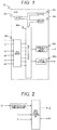
- FIG. 1 is a system block diagram illustrating a configuration of the engine control device.
- Output signals of an air flow sensor 1, a humidity sensor 3, an accelerator opening level sensor 12, a differential pressure sensor 43, an EGR temperature sensor 44, and a coolant temperature sensor are input to an input circuit 20a of the ECU 20.
- the input signals are not limited to those described above.
- the input signals received from each sensor are transmitted to an input port of the input/output port 20b.
- the value transmitted to the input port 20b is stored in a RAM 20c and is processed by the CPU 20e.
- a control program that describes contents of the computation process is written on a ROM 20d in advance.
- the driving circuit includes an electronic throttle driving circuit 20f and an EGR valve driving circuit 20m. Each circuit controls the electronic control throttle 2 and the EGR valve 41.
- the driving circuit is provided in the ECU 20.
- the present invention is not limited thereto. Instead, any one of the driving circuits may be provided in the ECU 20.
- the ECU 20 estimates the EGR percentage on the basis of the input signal and controls the throttle valve 2 and the EGR valve 41 depending on a required driving condition.
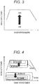
- FIG. 2 is a schematic logic diagram illustrating a control for the reduced and discharged exhaust gas performed in the ECU 20 of the engine control device.
- the exhaust gas control logic includes a required torque computation unit that computes a required torque and a required air amount on the basis of the output of the accelerator opening level sensor 12, and an EGR valve control unit that computes a control amount of the EGR valve on the basis of a fresh air moisture amount and an exhaust gas moisture amount computed from the output of the air flow sensor 1 and the output of the humidity sensor 3, and the required air amount.
- the accelerator opening level sensor 12 is input to the required torque computation unit, and the air flow sensor signal 1 and the humidity sensor signal 3 are input to the EGR valve control unit, so that the control for the EGR valve 41 and the throttle valve is performed.
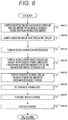
- FIG. 3 is a map which previously defines a stable combustion limitation mass on an engine map. As the engine output power increases from a low output power region, the stable combustion limitation mass tends to increase.
- the map of the stable combustion limitation mass is established at an ambient air temperature Tamb and a relative humidity of 100%. This is because, if the relative humidity is defined as 100%, it is possible to drive the engine without generating combustion instability under any humidity condition.
- the stable combustion limitation mass may be an in-cylinder mass that generates combustion instability under each driving condition, or a mass that minimizes the fuel consumption under each driving condition.
- a single map may be defined by mixing such definitions.
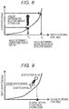
- FIG. 4 is a map which previously defines the EGR amount on the engine map.
- the EGR is introduced in order to reduce a pumping loss, such that the required EGR amount increases as the engine output power decreases.
- the EGR is introduced in order to suppress abnormal combustion, such that EGR amount tends to increase as the engine output power increases.
- the map is created at the ambient air temperature Tamb and a relative humidity of 100%. This is because, if the EGR amount is appropriately set at a relative humidity of 100%, it is possible to drive the engine without generating combustion instability under any humidity condition.
- FIG. 5 is a schematic system diagram illustrating an automobile in-cylinder injection type gasoline engine provided with a low-pressure EGR flow passage.
- the engine 100 is an automobile gasoline engine that performs spark ignition type combustion.
- An air flow sensor 1 that measures an intake air amount
- a humidity sensor 3 that detects an intake humidity
- a supercharger compressor 4a for supercharging the intake air
- an intercooler 7 for cooling the intake air
- an electronic control throttle 2 that adjusts the intake pipe pressure
- the humidity sensor 3 is a sensor capable of detecting a relative humidity and an absolute humidity.
- each cylinder of the engine 100 is provided with a fuel injection device (hereinafter, referred to as an "injector") 13 that injects fuel to the inside of the cylinder 14 and an ignition plug 16 that supplies ignition energy.
- injector fuel injection device
- variable valve 5 that adjusts the gas injected into the cylinder or discharged from the cylinder is provided in a cylinder head.
- the intake air amount of overall cylinders and the internal EGR amount are controlled by adjusting the variable valve 5.
- a high-pressure fuel pump for supplying high-pressure fuel to the fuel injection device 13 is connected to the fuel injection device 13 through a fuel pipe, and the fuel pipe is provided with a fuel pressure sensor for measuring the fuel injection pressure.
- a turbine 4b for exerting a rotation fore to the supercharger compressor 4a on the basis of the exhaust energy, an electronic control wastegate valve 11 for adjusting an exhaust flow rate flowing to the turbine, a three-way catalyst 10 that purifies the exhaust gas, and an air/fuel ratio sensor 9 as a sort of the air/fuel ratio detector that detects an air/fuel ratio of the exhaust gas in the upstream side of the three-way catalyst 10 are provided in respective suitable positions of the exhaust pipe 15.
- An EGR pipe 40 for recirculating the exhaust gas to the upstream side of the compressor 4a of the intake pipe from the downstream side of the catalyst 10 of the exhaust pipe is provided.
- an EGR cooler 42 for cooling the EGR an EGR valve (EGR mechanism) 41 for controlling the EGR flow rate, a differential pressure sensor 43 that detects a differential pressure around the EGR valve, and an EGR temperature sensor 44 that detects the EGR temperature are provided in respective suitable positions of the EGR pipe 40.
- a temperature sensor 45 that measures a temperature of the coolant circulating the engine is provided.
- the signals obtained from the air flow sensor 1, the humidity sensor 3, the air/fuel ratio sensor 9, the differential pressure sensor 43, and the EGR temperature sensor 44 are transmitted to an engine control unit (ECU) 20.
- the signal obtained from the accelerator opening level sensor 12 is transmitted to the ECU 20.
- the accelerator opening level sensor 12 detects a depression amount of the accelerator pedal, that is, an accelerator opening level.
- the ECU 20 computes the required torque on the basis of the output signal of the accelerator opening level sensor 12. That is, the accelerator opening level sensor 12 is used as a required torque detection sensor for detecting a torque required in the engine.
- the ECU 20 computes an engine rotation speed on the basis of the output signal of a crank angle sensor.
- the ECU 20 computes optimum values of major engine operation amounts such as the air flow rate, the fuel injection amount, the ignition timing, and the fuel pressure on the basis of the engine driving state obtained from various sensor output values.
- the fuel injection amount computed by the ECU 20 is converted into a valve open pulse signal, which is transmitted to the injector 13.
- the ignition signal is transmitted to the ignition plug 17 such that the ignition is performed at the ignition timing computed by the ECU 20.
- the throttle opening level computed by the ECU 20 is transmitted to the electronic control throttle 2 as a throttle driving signal.
- the EGR valve opening level computed by the ECU 20 is transmitted to the EGR valve 41 as an EGR valve opening level driving signal.
- Fuel is injected to the air flowing from the intake pipe into the cylinder 14 through the intake value to form a gas mixture.
- the gas mixture is exploded by a spark generated from the ignition plug 16 at a predetermined ignition timing, so that its combustion pressure presses down the piston to obtain an engine driving force.
- the exhaust gas subjected to explosion passes through the exhaust pipe 15 and is transferred to the three-way catalyst 10, and the exhaust component is purified in the three-way catalyst 10 and is discharged to the outside. Since the three-way catalyst 10 is provided upstream of the inlet port of the EGR pipe 40, it is possible to stabilize a composition of the recirculating exhaust gas. As a result, it is possible to stably obtain performance in the EGR amount control under any driving condition.
- FIG. 6 illustrates a computation process performed by the EGR valve control unit of FIG. 2 .
- step S601 the moisture amount in the fresh air introduced into the cylinder is computed.
- a mass fraction of the moisture Y H2O,air and a volume fraction ⁇ of the air are computed from an absolute humidity H air [kg/m 3 ] and an air density ⁇ air [kg/m 3 ] detected from the output of the humidity sensor as described below, and the air density is recorded on the ECU.
- the values described above are estimated from the detected information.
- W H2O and W air denote a molar mass [kg/mol] of water and a molar mass of air [kg/mol], respectively.
- the moisture flow rate in the fresh air and the fresh air proportion of the moisture amount introduced into the cylinder are computed as follows on the basis of the output m air [kg/s] of the air flow sensor 1 or the required air amount M air,R [kg/cycle] obtained by the required torque computation unit.
- Ne denotes an engine rotation number [rpm]. While the moisture can be indirectly detected as described below, it may contain many estimation errors. For this reason, by detecting an absolute value of the moisture amount from the humidity sensor, it is possible to compute the moisture amount with high accuracy and accurately set various control signals of the actuator, compared to a case where the moisture amount is indirectly detected.
- the humidity sensor 3 is not installed, substitution may be possible by indirectly detecting the humidity.
- the moisture amount flowing to the cylinder can be indirectly detected on the basis of a difference between the air amount computed from the output m air of the air flow sensor 1 during traveling at a constant torque and the required air amount M air,R as follows.
- m H 2 O , air m air 30 Ne ⁇ M air , R
- the mass fraction Y H2O,air and the volume fraction ⁇ can be estimated as follows.
- Y H 2 O , air m air 30 Ne ⁇ M air
- R m air 30 Ne ⁇ m air 30 Ne ⁇ M air
- M Fuel CM air
- R M Fuel C 1 ⁇ Y H 2 O
- C denotes a predetermined constant which is set to approximately "1/15" when combustion is performed at an ideal air/fuel ratio.
- step S602 the moisture amount of the recirculating exhaust gas is computed.
- an updated value of the detected moisture amount of the air is used.
- the air is a gas mixture containing nitrogen (79 vol%) and oxygen (21 vol%)
- perfect combustion is performed to generate water and carbon dioxide, and nitrogen remains without reaction
- the following relationship is established around the reaction.
- the left side refers to a cylinder state prior to the combustion
- the right side refers to a cylinder state subjected to the combustion.
- CnHm denotes a fuel molecule
- O2 denotes an oxygen molecule
- N2 denotes a nitrogen molecule
- CO2 denotes a carbon dioxide molecule
- H2O denotes a water molecule
- m denotes an average carbon number of the hydrocarbon molecule included in the fuel
- n denotes an average carbon number of the hydrocarbon molecule included in the fuel.
- the moisture amount of the recirculating exhaust gas is computed as follows.
- ⁇ m 2 + ⁇ 1 ⁇ ⁇ W H 2 O nW CO 2 + m 2 + ⁇ 1 ⁇ ⁇ W H 2 O + 3.76 n + m 4 W N 2
- WH2O weight-to-weight ratio
- WCO2 weight-to-weight ratio
- WN2 weight-to-weight ratio
- step S603 the stable combustion limitation mass is computed.
- the stable combustion limitation mass M max, map value may be extracted from the stable combustion limitation mass map of FIG. 3 depending on a driving condition.
- the EGR amount M EGR, map may be read from the EGR gas amount map of FIG. 4 depending on the current driving condition, and computation may be performed by applying Equation 7.
- the factor " ⁇ " is a coefficient set by assuming that carbon dioxide or nitrogen of ⁇ kg and water of 1 kg equally affect the combustion stability and is determined on the basis of experimental measurement.
- M max , map 1 ⁇ ⁇ + ⁇ M EGR , map + ⁇ M H 2 O , air , 100 % + M air + M fuel
- step S604 the recirculating exhaust gas amount is computed considering the moisture amount finally introduced into the cylinder.
- combustion occurs by flam propagation.
- the influence on the flame propagation is different between carbon dioxide and water.
- a reduction amount of the flame propagation rate is different between a case where water having a mass ratio of 10% as a dilution gas is added to a gas mixture of fuel and air having an equivalent ratio of "1" and a case where carbon dioxide having a mass ratio of 10% is added as a dilution gas.
- Combustion instability occurring in the engine when the exhaust gas is recirculated means that influence on combustion instability is different between water and carbon dioxide due to reduction of the flame propagation rate.
- M limit M CO 2 , EGR + M N 2 , EGR + ⁇ M H 2 O , air + M H 2 O , EGR + M fuel + M air
- Equation 9 can be substituted with Equation 10 by applying the factor " ⁇ " defined in Equation 6.
- M limit 1 ⁇ ⁇ + ⁇ B M EGR + ⁇ M H 2 O , air + M fuel + M air
- Equation 11 It is possible to obtain the EGR gas mass at the combustion stabilization limitation from Equation 11 if the effective gas mass M limit at the combustion stabilization limitation has the existing value from Equation 10.
- M EGR M limit ⁇ ⁇ M H 2 O , air ⁇ M fuel ⁇ M air 1 ⁇ ⁇ + ⁇
- the factor “ ⁇ ” is determined through an engine test or a simulation test such as numerical simulation in advance.
- the factor “ ⁇ ” is set to 1 to 2 in many cases, but is not limited thereto.
- the target exhaust gas amount is set on the basis of the following equation by assuming that water and carbon dioxide have the same responsiveness.
- M EGR M max , map ⁇ ⁇ M H 2 O , air ⁇ M fuel ⁇ M air
- the EGR amount is determined by computing the moisture amount M H2O , air introduced from the fresh air and the moisture amount ⁇ introduced from the exhaust gas. Therefore, it is possible to control the EGR amount depending on the moisture amount. Accordingly, it is possible to set the EGR amount depending on the moisture amount in the cylinder. As a result, the control can be performed such that reduction of the fuel consumption can be maximized depending on the humidity of the air.
- map of FIG. 3 showing the combustion stabilization limitation mass M max map desirably has a value obtained by computing the right side of Equation 12.
- step S605 influence from the moisture amount in the fresh air and influence from the recirculating EGR gas amount are corrected, and a throttle opening level necessary to introduce the required air amount is computed.
- a map representing a relationship between the flow rate and the throttle opening level is prepared in the ECU in advance as illustrated in FIG. 8 , and the throttle opening level is computed from this relationship.
- the required air amount is introduced into the cylinder by controlling the throttle opening level considering that the moisture of the air caused by humidity or the EGR gas amount is mixed.
- step S606 the EGR valve opening level is set on the basis of a relationship between the EGR valve opening level and the EGR flow rate as illustrated in FIG. 9 .
- the EGR valve opening level is set from the map data of FIG. 9 depending on the target exhaust gas amount. If a difference is generated between the detection value detected in Equation 15 and the target value, the valve opening level is set to increase or decrease depending on the difference of the detection value.
- m EGR P a ⁇ A ⁇ C 2 ⁇ ⁇ P EGR ⁇ R EGR T EGR
- T EGR denotes an EGR gas temperature measured using an EGR gas temperature sensor (not illustrated in FIG. 5 ) or an estimated value of the EGR gas temperature estimated from the water temperature.
- step S607 the control is performed on the basis of the throttle opening level obtained in step S605.
- step S608 the EGR value is controlled on the basis of the EGR valve opening level set in step S606.
- the engine is controlled through the aforementioned step.
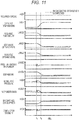
- FIG. 7 illustrates operations of each actuator and a change of detection value when the control of FIG. 6 is performed.
- the external humidity condition is changed, and the required torque is constant.
- the external air humidity starts to decrease from the timing t1, and a change of the detection value is removed at the timing t2.
- the stable combustion limitation mass computed in step S603 of FIG. 6 there is no change in the stable combustion limitation mass computed in step S603 of FIG. 6 .
- the target exhaust gas amount computed in step S605 of FIG. 6 increases at and after the timing t1.
- the setting value of the EGR valve opening level also gradually increases from the timing t1 to the timing t2.
- step S605 the throttle valve opening level is set to be larger than the value of the timing t1. As a result, the throttle valve opening level increases, and the air amount introduced into the cylinder is controlled to be constant. As a result of this control, the amount of the introduced exhaust gas increases as the external air humidity increases. This is because the EGR amount is corrected by considering the moisture amount through the computation of step S605.
- Example 2 illustrates the engine configuration
- FIG. 2 illustrates the ECU configuration
- FIG. 10 illustrates a computation process performed by the EGR valve control unit of FIG. 2 .
- Example 2 is similar to Example 1 except for the process of step S1004.
- the target exhaust gas amount is set in step S1004
- the catalyst temperature is estimated depending on an increase of the coolant temperature measured using the coolant temperature sensor or the time from the engine start.
- the target exhaust gas amount is set depending on the estimated catalyst activation state.
- the exhaust gas prior to activation of the catalyst contains a lot of active chemical species contributing to the combustion stability, such as carbon monoxide (CO) or nitrogen monoxide (NO), compared to the catalyst warm-up steady state.
- CO carbon monoxide
- NO nitrogen monoxide
- ⁇ M Rad denotes a correction factor for considering the influence of the active chemical species.
- the factor " ⁇ M Rad” changes depending on catalyst activity. Under the catalyst inactivation state, carbon monoxide (CO) or nitrogen dioxide (NO) generated by combustion remains without being converted. Therefore, the factor “ ⁇ M Rad " has a large value. As the catalyst is activated, the factor “ ⁇ M Rad " becomes zero.
- the target exhaust gas amount can be appropriately changed by changing the factor " ⁇ M Rad " on the basis of the catalyst activity detected by the water temperature and the time elapsing from the engine start. The change of the factor " ⁇ M Rad " relative to the catalyst activity is investigated through an engine test in advance, and the data is stored in the ECU. FIG.
- step 11 illustrates operations of the actuator when the control of FIG. 10 is performed. It is assumed that the catalyst temperature estimated on the basis of the coolant temperature and the time elapsing from the engine start is changed, and the required torque is constant. It is assumed that the detected catalyst temperature starts to increase from the timing t1 and rises to the temperature of the timing t2 at which the catalyst is activated. In this case, the map value of the stable combustion limitation mass computed in step S1003 of FIG. 10 does not temporally change. Meanwhile, the target exhaust gas amount computed in step S1005 of FIG. 10 decreases from the timing t1 to the timing t2. This is because the target exhaust gas amount of Equation 16 is corrected on the basis of the detected catalyst activation state (catalyst temperature).
- the value is set such that the target exhaust gas amount is reduced as the catalyst temperature increases from the timing t1 to the timing t2.
- the setting value of the EGR valve opening level is set to gradually decrease from the timing t1 to the timing t2.
- the target exhaust gas amount is reduced. Therefore, in step S1005, the throttle valve opening level is set to smaller than that of the timing t1 as the target exhaust gas amount is reduced.
- the control is performed such that the throttle valve opening level decreases, and the air amount introduced into the cylinder becomes constant. As a result of this control the introduced exhaust gas amount changes to decrease as the catalyst temperature increases.
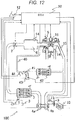
- FIG. 12 illustrates a configuration of the engine
- FIG. 13 illustrates a computation process performed by the EGR valve control unit of FIG. 2 .
- the configuration of the engine of FIG. 12 is similar to that of FIG. 5 except for the exhaust gas recirculation mechanism.
- the exhaust gas is extracted from the upstream side of the turbine of the turbocharger and is recirculated to the downstream side of the compressor.
- the computation process of FIG. 13 is similar to that of Example 1 of FIG. 6 except for step S1304.
- step S1304 when the target exhaust gas amount is set, the coolant temperature measured using the coolant temperature sensor or the target exhaust gas amount depending on the detected EGR gas temperature are set.
- M EGR M max , map ⁇ ⁇ M H 2 O , air ⁇ M fuel ⁇ M air 1 ⁇ ⁇ + ⁇ + ⁇ M T
- ⁇ M T denotes a correction factor for considering the exhaust gas temperature.
- the temperature of the exhaust gas introduced into the engine cylinder is different depending on the coolant temperature. Specifically, immediately after the engine start, the coolant temperature is low. Therefore, the exhaust gas temperature is lowered relative to the temperature of the warm-up steady state. After sufficient time elapses from the engine start, the exhaust gas temperature reaches the warm-up steady state temperature (higher than the engine start temperature). As described above, if the recirculating exhaust gas temperature decreases, the temperature of the gas mixture is lowered, and unstable combustion easily occurs. For this reason, the correction depending on the EGR gas temperature is effective in order to stabilize combustion while maximizing reduction of the fuel consumption.
- the stable combustion limitation mass M max, map defined in FIG. 3 is determined depending on the steady state after the warm-up.
- the value of " ⁇ M T " is set to be equal to or smaller than zero. That is, if the water temperature or the EGR gas temperature is low, the target exhaust gas amount is set to be smaller than the EGR amount computed from the stable combustion limitation gas mass M max, map . If the water temperature sufficiently increases, or the EGR gas temperature sufficiently increases, the value of " ⁇ M T " is set to zero, the same amount as the EGR amount computed from the stable combustion limitation gas mass set depending on a reference condition is set to the target exhaust gas amount. A change of " ⁇ M T " with respect to the water temperature or the EGR gas temperature is investigated through an engine test in advance, and the resulting data is stored in the ECU.
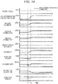
- FIG. 14 illustrates various operations of the actuator when the processing is performed along the control flowchart of FIG. 13 . It is assumed that the required torque is constant. It is assumed that the coolant temperature detected from the coolant temperature sensor during driving or the EGR gas temperature detected from the EGR temperature sensor 44 starts to increase from the timing t1 and reaches the steady state at the timing t2. In this case, the value of the stable combustion limitation mass computed in step S1303 of FIG. 13 does not temporally change. However, the target exhaust gas amount computed in step S1305 of FIG. 13 gradually increases from the timing t1 to the timing t2 in order to compute the target exhaust gas amount using Equation 17 on the basis of the coolant temperature or the exhaust gas temperature.
- step S1305 the throttle valve opening level is set to be larger than that of the timing t1 as the target exhaust gas amount decreases in step S1305.
- the control is performed such that the throttle valve opening level increases, and the air amount introduced into the cylinder becomes constant.
- the introduced exhaust gas amount is changed to increase as the coolant temperature or the exhaust gas temperature increases.
- FIG. 15 illustrates a configuration of the engine
- FIG. 16 illustrates a computation process performed by the EGR valve control unit of FIG. 2 .
- the configuration of FIG. 15 is similar to that of FIG. 5 except for the exhaust gas recirculation mechanism.
- the configuration of FIG. 5 is combined with a mechanism for extracting the exhaust gas from the upstream side of the turbine of the turbocharger and recirculating the exhaust gas to the downstream side of the compressor.
- the computation process of FIG. 16 is similar to that of Example 1 of FIG. 6 except for steps S1609 and S1610 of FIG. 16 .
- step S1609 it is determined whether the recirculating exhaust gas is applied to the high-pressure EGR system or the low-pressure EGR system. For example, if the required torque is abruptly changed, and high responsiveness of the exhaust gas is necessary, it is determined that the high-pressure exhaust gas is employed. If it is difficult to recirculate the necessary exhaust gas in the high-pressure EGR system under a supercharging condition, the low-pressure EGR system is employed. In other cases, the EGR system may be determined depending on the water temperature, the time elapsing from the engine start, or the catalyst activation status. If the high-pressure EGR system is selected in step S1609, the process advances to step S1610.
- step S1610 the target exhaust gas amount is changed to the target exhaust gas amount using Equation 18.
- M EGR M max , map ⁇ ⁇ M H 2 O , air ⁇ M fuel ⁇ M air 1 ⁇ ⁇ + ⁇ + ⁇ M high
- ⁇ M high denotes the correction factor when the high-pressure EGR system is employed.
- the exhaust gas is returned to the intake side without passing through the catalyst. Therefore, the exhaust gas contains a lot of active chemical species such as carbon monoxide or nitrogen oxide.
- the exhaust gas passes through the catalyst and is then returned to the intake side. Therefore, there are little active chemical species in most cases, and there are stable chemical species. Since the active chemical species act to accelerate the combustion rate, the stable combustion limitation mass increases when there are many active chemical species, compared to the case of the stable chemical species. For this reason, it may be possible to recirculate more exhaust gas.
- the factor " ⁇ M high” It is necessary to determine the factor " ⁇ M high " in advance through an engine test.
- the stable combustion mass limitation M max, map in the warm-up steady state is determined in the case of the low-pressure EGR system, and the factor " ⁇ M high " is then determined.
- the factor " ⁇ M high” has a positive value. That is, in the case of the high-pressure EGR system, it is possible to set the larger target exhaust gas amount, compared to the case of the low-pressure EGR system.
- the difference " ⁇ M high " of the EGR amount that can be recirculated is investigated in advance through an engine test individually for the case of the low-pressure EGR system and for the case of the high-pressure EGR system, and the resulting data are stored in the ECU.
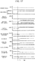
- FIG. 17 illustrates various operations of the actuator when the computation process of FIG. 16 is performed. It is assumed that the required torque is constant. It is assumed that the high-pressure EGR system is employed in step S1609 of the flowchart at the timing t1. In this case, there is no change in the map value of the stable combustion limitation mass read in step S1603 of FIG. 15 . However, at and after the timing t1, the target exhaust gas amount is changed in step S1610 of FIG. 15 , and thus, the target exhaust gas amount increases. As a result, the EGR valve opening level also increases at and after the timing t1. Although the required torque does not change, the target exhaust gas amount increases.
- step S1605 the throttle valve opening level is set to be larger than that of the timing t1 as the target exhaust gas amount increases.
- the control is performed such that the throttle valve opening level increases, and the air amount introduced into the cylinder becomes constant.
- the introduced exhaust gas amount is larger when the high-pressure EGR system is employed, compared to a case where the low-pressure EGR system is employed.
- the EGR amount introduced when the EGR system is switched to the high-pressure EGR increases. Therefore, the pumping loss is reduced, and accordingly, the fuel consumption is reduced.
Landscapes
- Engineering & Computer Science (AREA)
- Chemical & Material Sciences (AREA)
- Combustion & Propulsion (AREA)
- Mechanical Engineering (AREA)
- General Engineering & Computer Science (AREA)
- Output Control And Ontrol Of Special Type Engine (AREA)
- Combined Controls Of Internal Combustion Engines (AREA)
- Exhaust-Gas Circulating Devices (AREA)
Applications Claiming Priority (2)
| Application Number | Priority Date | Filing Date | Title |
|---|---|---|---|
| JP2014240729A JP6488113B2 (ja) | 2014-11-28 | 2014-11-28 | 内燃機関の制御装置 |
| PCT/JP2015/080307 WO2016084538A1 (ja) | 2014-11-28 | 2015-10-28 | 内燃機関の制御装置 |
Publications (3)
| Publication Number | Publication Date |
|---|---|
| EP3225821A1 true EP3225821A1 (de) | 2017-10-04 |
| EP3225821A4 EP3225821A4 (de) | 2018-07-04 |
| EP3225821B1 EP3225821B1 (de) | 2020-08-05 |
Family
ID=56074113
Family Applications (1)
| Application Number | Title | Priority Date | Filing Date |
|---|---|---|---|
| EP15862692.9A Active EP3225821B1 (de) | 2014-11-28 | 2015-10-28 | Steuerungsvorrichtung für verbrennungsmotor |
Country Status (5)
| Country | Link |
|---|---|
| US (1) | US10280855B2 (de) |
| EP (1) | EP3225821B1 (de) |
| JP (1) | JP6488113B2 (de) |
| CN (1) | CN107002565B (de) |
| WO (1) | WO2016084538A1 (de) |
Families Citing this family (3)
| Publication number | Priority date | Publication date | Assignee | Title |
|---|---|---|---|---|
| JP6421763B2 (ja) * | 2016-01-13 | 2018-11-14 | トヨタ自動車株式会社 | 湿度センサの異常検出装置 |
| CN114109626B (zh) * | 2021-11-01 | 2024-01-19 | 东风商用车有限公司 | 天然气发动机egr闭环控制方法、系统及车辆 |
| JP7518868B2 (ja) * | 2022-03-31 | 2024-07-18 | 日本碍子株式会社 | Co2質量推定システム、排ガスの組成比推定方法、およびco2質量推定方法 |
Family Cites Families (25)
| Publication number | Priority date | Publication date | Assignee | Title |
|---|---|---|---|---|
| US6062204A (en) * | 1998-10-15 | 2000-05-16 | Ford Global Technologies, Inc. | Engine control system and method with atmospheric humidity compensation |
| US6725848B2 (en) * | 2002-01-18 | 2004-04-27 | Detroit Diesel Corporation | Method of controlling exhaust gas recirculation system based upon humidity |
| JP2009024685A (ja) * | 2007-07-24 | 2009-02-05 | Toyota Motor Corp | 内燃機関の制御装置 |
| JP2010090806A (ja) * | 2008-10-08 | 2010-04-22 | Toyota Industries Corp | 排気ガス再循環システム |
| FR2938301B1 (fr) * | 2008-11-13 | 2010-11-12 | Peugeot Citroen Automobiles Sa | Procede et dispositif de reglage d'une recirculation de gaz d'echappement pour un moteur a combustion interne |
| JP2010133287A (ja) * | 2008-12-02 | 2010-06-17 | Toyota Motor Corp | 内燃機関の制御装置 |
| US7715976B1 (en) * | 2009-04-02 | 2010-05-11 | Ford Global Technologies, Llc | EGR detection via humidity detection |
| JP5171740B2 (ja) * | 2009-06-17 | 2013-03-27 | 本田技研工業株式会社 | 内燃機関の制御装置 |
| DE102009037923A1 (de) * | 2009-08-19 | 2011-02-24 | Behr America, Inc., Troy | Anordnung zur Rückführung und Kühlung von Abgas einer Brennkraftmaschine |
| WO2011141989A1 (ja) * | 2010-05-10 | 2011-11-17 | トヨタ自動車株式会社 | 内燃機関の制御装置 |
| US8020538B2 (en) | 2010-05-28 | 2011-09-20 | Ford Global Technologies, Llc | Cooled EGR system for coolant heating during cold engine start |
| JP5382368B2 (ja) * | 2010-12-21 | 2014-01-08 | 三菱自動車工業株式会社 | エンジンの制御装置 |
| JP5741032B2 (ja) * | 2011-02-08 | 2015-07-01 | トヨタ自動車株式会社 | 内燃機関の排気再循環システム |
| JP5664774B2 (ja) * | 2011-05-26 | 2015-02-04 | トヨタ自動車株式会社 | 内燃機関の制御装置 |
| US9051901B2 (en) * | 2011-06-07 | 2015-06-09 | Ford Global Technologies, Llc | Exhaust gas recirculation (EGR) system |
| US8301358B2 (en) * | 2011-06-21 | 2012-10-30 | Ford Global Technologies, Llc | Method of engine starting |
| US9038580B2 (en) * | 2012-02-21 | 2015-05-26 | Ford Global Technologies, Llc | Method and system for engine dilution control |
| US9382838B2 (en) * | 2012-05-17 | 2016-07-05 | Ford Global Technologies, Llc | Boost reservoir and throttle coordination |
| DE102012104724A1 (de) * | 2012-05-31 | 2013-12-05 | Fev Gmbh | Abgasrückführvorrichtung für einen Verbrennungsmotor |
| US9175616B2 (en) | 2012-10-10 | 2015-11-03 | Ford Global Technologies, Llc | Approach for controlling exhaust gas recirculation |
| US9145823B2 (en) | 2012-10-19 | 2015-09-29 | Ford Global Technologies, Llc | Method for purging condensate from a charge air cooler |
| US9803590B2 (en) * | 2013-02-22 | 2017-10-31 | Ford Global Technologies, Llc | Humidity sensor diagnostics |
| US9341133B2 (en) * | 2013-03-06 | 2016-05-17 | GM Global Technology Operations LLC | Exhaust gas recirculation control systems and methods |
| JP6210744B2 (ja) * | 2013-06-10 | 2017-10-11 | ダイハツ工業株式会社 | 内燃機関の制御装置 |
| US9109505B2 (en) * | 2013-08-13 | 2015-08-18 | Ford Global Technologies, Llc | Methods and systems for condensation control |
-
2014
- 2014-11-28 JP JP2014240729A patent/JP6488113B2/ja active Active
-
2015
- 2015-10-28 WO PCT/JP2015/080307 patent/WO2016084538A1/ja not_active Ceased
- 2015-10-28 EP EP15862692.9A patent/EP3225821B1/de active Active
- 2015-10-28 CN CN201580063345.4A patent/CN107002565B/zh active Active
- 2015-10-28 US US15/528,970 patent/US10280855B2/en active Active
Also Published As
| Publication number | Publication date |
|---|---|
| WO2016084538A1 (ja) | 2016-06-02 |
| US10280855B2 (en) | 2019-05-07 |
| CN107002565A (zh) | 2017-08-01 |
| EP3225821B1 (de) | 2020-08-05 |
| CN107002565B (zh) | 2020-01-14 |
| EP3225821A4 (de) | 2018-07-04 |
| JP6488113B2 (ja) | 2019-03-20 |
| US20170268442A1 (en) | 2017-09-21 |
| JP2016102442A (ja) | 2016-06-02 |
Similar Documents
| Publication | Publication Date | Title |
|---|---|---|
| US9109545B2 (en) | Systems and methods for controlling exhaust gas recirculation composition | |
| EP3187719B1 (de) | Vorrichtung für einen verbrennungsmotor | |
| US20130268176A1 (en) | Exhaust gas recirculation control systems and methods for low engine delta pressure conditions | |
| US7620490B2 (en) | Fuel injection control device for internal combustion engine | |
| US10066584B2 (en) | Error determination unit | |
| US10208692B2 (en) | Misfire detecting system for engine | |
| CN110094271A (zh) | 用于排气再循环控制的方法和系统 | |
| CN104165099A (zh) | 用于运行尤其机动车的自行点火的内燃机的废气再循环系统的方法和装置 | |
| US20080156302A1 (en) | Exhaust gas recirculation estimation system | |
| EP3225821B1 (de) | Steuerungsvorrichtung für verbrennungsmotor | |
| KR101775965B1 (ko) | 이중 분사 엔진의 공연비 제어 방법 및 장치 | |
| JP2009047130A (ja) | 内燃機関の制御装置 | |
| US9822697B2 (en) | Turbine expansion ratio estimation for model-based boost control | |
| EP3757375A1 (de) | Sauerstoffkonzentrationsbasiertes abgasrückführungsflussratenkompensationssteuerungsverfahren und motorsystem | |
| EP2650514A1 (de) | Steuerungsvorrichtung für einen verbrennungsmotor | |
| EP2935845B1 (de) | Abgasrückführungssteuerungsverfahren und -system | |
| US20240229731A1 (en) | Control Device for Internal Combustion Engine | |
| CN110168212A (zh) | 内燃机的进气控制方法以及进气控制装置 | |
| JP2012158997A (ja) | 内燃機関の制御装置 | |
| JP4479810B2 (ja) | 排気再循環式内燃機関の燃料噴射量制御装置 | |
| JP2013148067A (ja) | 内燃機関の制御装置 | |
| JP2011157942A (ja) | 内燃機関のegr制御装置 | |
| CA2894291C (en) | Fuel injector trimming in a multi-fuel engine | |
| JP5517110B2 (ja) | 内燃機関のegr制御装置 | |
| JP2012229622A (ja) | 内燃機関のegr制御装置 |
Legal Events
| Date | Code | Title | Description |
|---|---|---|---|
| STAA | Information on the status of an ep patent application or granted ep patent |
Free format text: STATUS: THE INTERNATIONAL PUBLICATION HAS BEEN MADE |
|
| PUAI | Public reference made under article 153(3) epc to a published international application that has entered the european phase |
Free format text: ORIGINAL CODE: 0009012 |
|
| STAA | Information on the status of an ep patent application or granted ep patent |
Free format text: STATUS: REQUEST FOR EXAMINATION WAS MADE |
|
| 17P | Request for examination filed |
Effective date: 20170628 |
|
| AK | Designated contracting states |
Kind code of ref document: A1 Designated state(s): AL AT BE BG CH CY CZ DE DK EE ES FI FR GB GR HR HU IE IS IT LI LT LU LV MC MK MT NL NO PL PT RO RS SE SI SK SM TR |
|
| AX | Request for extension of the european patent |
Extension state: BA ME |
|
| DAV | Request for validation of the european patent (deleted) | ||
| DAX | Request for extension of the european patent (deleted) | ||
| A4 | Supplementary search report drawn up and despatched |
Effective date: 20180605 |
|
| RIC1 | Information provided on ipc code assigned before grant |
Ipc: F02D 41/06 20060101ALI20180529BHEP Ipc: F02D 45/00 20060101ALI20180529BHEP Ipc: F02D 41/00 20060101ALI20180529BHEP Ipc: F02D 21/08 20060101AFI20180529BHEP |
|
| TPAC | Observations filed by third parties |
Free format text: ORIGINAL CODE: EPIDOSNTIPA |
|
| TPAC | Observations filed by third parties |
Free format text: ORIGINAL CODE: EPIDOSNTIPA |
|
| STAA | Information on the status of an ep patent application or granted ep patent |
Free format text: STATUS: EXAMINATION IS IN PROGRESS |
|
| 17Q | First examination report despatched |
Effective date: 20190729 |
|
| GRAP | Despatch of communication of intention to grant a patent |
Free format text: ORIGINAL CODE: EPIDOSNIGR1 |
|
| STAA | Information on the status of an ep patent application or granted ep patent |
Free format text: STATUS: GRANT OF PATENT IS INTENDED |
|
| INTG | Intention to grant announced |
Effective date: 20200401 |
|
| GRAS | Grant fee paid |
Free format text: ORIGINAL CODE: EPIDOSNIGR3 |
|
| GRAA | (expected) grant |
Free format text: ORIGINAL CODE: 0009210 |
|
| STAA | Information on the status of an ep patent application or granted ep patent |
Free format text: STATUS: THE PATENT HAS BEEN GRANTED |
|
| AK | Designated contracting states |
Kind code of ref document: B1 Designated state(s): AL AT BE BG CH CY CZ DE DK EE ES FI FR GB GR HR HU IE IS IT LI LT LU LV MC MK MT NL NO PL PT RO RS SE SI SK SM TR |
|
| REG | Reference to a national code |
Ref country code: GB Ref legal event code: FG4D |
|
| REG | Reference to a national code |
Ref country code: CH Ref legal event code: EP |
|
| REG | Reference to a national code |
Ref country code: AT Ref legal event code: REF Ref document number: 1299020 Country of ref document: AT Kind code of ref document: T Effective date: 20200815 |
|
| REG | Reference to a national code |
Ref country code: DE Ref legal event code: R096 Ref document number: 602015057156 Country of ref document: DE |
|
| REG | Reference to a national code |
Ref country code: IE Ref legal event code: FG4D |
|
| REG | Reference to a national code |
Ref country code: LT Ref legal event code: MG4D |
|
| REG | Reference to a national code |
Ref country code: NL Ref legal event code: MP Effective date: 20200805 |
|
| REG | Reference to a national code |
Ref country code: AT Ref legal event code: MK05 Ref document number: 1299020 Country of ref document: AT Kind code of ref document: T Effective date: 20200805 |
|
| PG25 | Lapsed in a contracting state [announced via postgrant information from national office to epo] |
Ref country code: PT Free format text: LAPSE BECAUSE OF FAILURE TO SUBMIT A TRANSLATION OF THE DESCRIPTION OR TO PAY THE FEE WITHIN THE PRESCRIBED TIME-LIMIT Effective date: 20201207 Ref country code: BG Free format text: LAPSE BECAUSE OF FAILURE TO SUBMIT A TRANSLATION OF THE DESCRIPTION OR TO PAY THE FEE WITHIN THE PRESCRIBED TIME-LIMIT Effective date: 20201105 Ref country code: ES Free format text: LAPSE BECAUSE OF FAILURE TO SUBMIT A TRANSLATION OF THE DESCRIPTION OR TO PAY THE FEE WITHIN THE PRESCRIBED TIME-LIMIT Effective date: 20200805 Ref country code: LT Free format text: LAPSE BECAUSE OF FAILURE TO SUBMIT A TRANSLATION OF THE DESCRIPTION OR TO PAY THE FEE WITHIN THE PRESCRIBED TIME-LIMIT Effective date: 20200805 Ref country code: HR Free format text: LAPSE BECAUSE OF FAILURE TO SUBMIT A TRANSLATION OF THE DESCRIPTION OR TO PAY THE FEE WITHIN THE PRESCRIBED TIME-LIMIT Effective date: 20200805 Ref country code: SE Free format text: LAPSE BECAUSE OF FAILURE TO SUBMIT A TRANSLATION OF THE DESCRIPTION OR TO PAY THE FEE WITHIN THE PRESCRIBED TIME-LIMIT Effective date: 20200805 Ref country code: AT Free format text: LAPSE BECAUSE OF FAILURE TO SUBMIT A TRANSLATION OF THE DESCRIPTION OR TO PAY THE FEE WITHIN THE PRESCRIBED TIME-LIMIT Effective date: 20200805 Ref country code: NO Free format text: LAPSE BECAUSE OF FAILURE TO SUBMIT A TRANSLATION OF THE DESCRIPTION OR TO PAY THE FEE WITHIN THE PRESCRIBED TIME-LIMIT Effective date: 20201105 Ref country code: FI Free format text: LAPSE BECAUSE OF FAILURE TO SUBMIT A TRANSLATION OF THE DESCRIPTION OR TO PAY THE FEE WITHIN THE PRESCRIBED TIME-LIMIT Effective date: 20200805 Ref country code: GR Free format text: LAPSE BECAUSE OF FAILURE TO SUBMIT A TRANSLATION OF THE DESCRIPTION OR TO PAY THE FEE WITHIN THE PRESCRIBED TIME-LIMIT Effective date: 20201106 |
|
| PG25 | Lapsed in a contracting state [announced via postgrant information from national office to epo] |
Ref country code: PL Free format text: LAPSE BECAUSE OF FAILURE TO SUBMIT A TRANSLATION OF THE DESCRIPTION OR TO PAY THE FEE WITHIN THE PRESCRIBED TIME-LIMIT Effective date: 20200805 Ref country code: RS Free format text: LAPSE BECAUSE OF FAILURE TO SUBMIT A TRANSLATION OF THE DESCRIPTION OR TO PAY THE FEE WITHIN THE PRESCRIBED TIME-LIMIT Effective date: 20200805 Ref country code: NL Free format text: LAPSE BECAUSE OF FAILURE TO SUBMIT A TRANSLATION OF THE DESCRIPTION OR TO PAY THE FEE WITHIN THE PRESCRIBED TIME-LIMIT Effective date: 20200805 Ref country code: LV Free format text: LAPSE BECAUSE OF FAILURE TO SUBMIT A TRANSLATION OF THE DESCRIPTION OR TO PAY THE FEE WITHIN THE PRESCRIBED TIME-LIMIT Effective date: 20200805 Ref country code: IS Free format text: LAPSE BECAUSE OF FAILURE TO SUBMIT A TRANSLATION OF THE DESCRIPTION OR TO PAY THE FEE WITHIN THE PRESCRIBED TIME-LIMIT Effective date: 20201205 |
|
| PG25 | Lapsed in a contracting state [announced via postgrant information from national office to epo] |
Ref country code: DK Free format text: LAPSE BECAUSE OF FAILURE TO SUBMIT A TRANSLATION OF THE DESCRIPTION OR TO PAY THE FEE WITHIN THE PRESCRIBED TIME-LIMIT Effective date: 20200805 Ref country code: CZ Free format text: LAPSE BECAUSE OF FAILURE TO SUBMIT A TRANSLATION OF THE DESCRIPTION OR TO PAY THE FEE WITHIN THE PRESCRIBED TIME-LIMIT Effective date: 20200805 Ref country code: SM Free format text: LAPSE BECAUSE OF FAILURE TO SUBMIT A TRANSLATION OF THE DESCRIPTION OR TO PAY THE FEE WITHIN THE PRESCRIBED TIME-LIMIT Effective date: 20200805 Ref country code: RO Free format text: LAPSE BECAUSE OF FAILURE TO SUBMIT A TRANSLATION OF THE DESCRIPTION OR TO PAY THE FEE WITHIN THE PRESCRIBED TIME-LIMIT Effective date: 20200805 Ref country code: EE Free format text: LAPSE BECAUSE OF FAILURE TO SUBMIT A TRANSLATION OF THE DESCRIPTION OR TO PAY THE FEE WITHIN THE PRESCRIBED TIME-LIMIT Effective date: 20200805 |
|
| REG | Reference to a national code |
Ref country code: DE Ref legal event code: R097 Ref document number: 602015057156 Country of ref document: DE |
|
| PG25 | Lapsed in a contracting state [announced via postgrant information from national office to epo] |
Ref country code: AL Free format text: LAPSE BECAUSE OF FAILURE TO SUBMIT A TRANSLATION OF THE DESCRIPTION OR TO PAY THE FEE WITHIN THE PRESCRIBED TIME-LIMIT Effective date: 20200805 |
|
| REG | Reference to a national code |
Ref country code: CH Ref legal event code: PL |
|
| PLBE | No opposition filed within time limit |
Free format text: ORIGINAL CODE: 0009261 |
|
| STAA | Information on the status of an ep patent application or granted ep patent |
Free format text: STATUS: NO OPPOSITION FILED WITHIN TIME LIMIT |
|
| PG25 | Lapsed in a contracting state [announced via postgrant information from national office to epo] |
Ref country code: MC Free format text: LAPSE BECAUSE OF FAILURE TO SUBMIT A TRANSLATION OF THE DESCRIPTION OR TO PAY THE FEE WITHIN THE PRESCRIBED TIME-LIMIT Effective date: 20200805 Ref country code: SK Free format text: LAPSE BECAUSE OF FAILURE TO SUBMIT A TRANSLATION OF THE DESCRIPTION OR TO PAY THE FEE WITHIN THE PRESCRIBED TIME-LIMIT Effective date: 20200805 Ref country code: LU Free format text: LAPSE BECAUSE OF NON-PAYMENT OF DUE FEES Effective date: 20201028 |
|
| 26N | No opposition filed |
Effective date: 20210507 |
|
| REG | Reference to a national code |
Ref country code: BE Ref legal event code: MM Effective date: 20201031 |
|
| GBPC | Gb: european patent ceased through non-payment of renewal fee |
Effective date: 20201105 |
|
| PG25 | Lapsed in a contracting state [announced via postgrant information from national office to epo] |
Ref country code: IT Free format text: LAPSE BECAUSE OF FAILURE TO SUBMIT A TRANSLATION OF THE DESCRIPTION OR TO PAY THE FEE WITHIN THE PRESCRIBED TIME-LIMIT Effective date: 20200805 Ref country code: FR Free format text: LAPSE BECAUSE OF NON-PAYMENT OF DUE FEES Effective date: 20201031 |
|
| PG25 | Lapsed in a contracting state [announced via postgrant information from national office to epo] |
Ref country code: SI Free format text: LAPSE BECAUSE OF FAILURE TO SUBMIT A TRANSLATION OF THE DESCRIPTION OR TO PAY THE FEE WITHIN THE PRESCRIBED TIME-LIMIT Effective date: 20200805 Ref country code: LI Free format text: LAPSE BECAUSE OF NON-PAYMENT OF DUE FEES Effective date: 20201031 Ref country code: BE Free format text: LAPSE BECAUSE OF NON-PAYMENT OF DUE FEES Effective date: 20201031 Ref country code: CH Free format text: LAPSE BECAUSE OF NON-PAYMENT OF DUE FEES Effective date: 20201031 |
|
| REG | Reference to a national code |
Ref country code: DE Ref legal event code: R081 Ref document number: 602015057156 Country of ref document: DE Owner name: HITACHI ASTEMO, LTD., HITACHINAKA-SHI, JP Free format text: FORMER OWNER: HITACHI AUTOMOTIVE SYSTEMS, LTD., HITACHINAKA-SHI, IBARAKI, JP |
|
| PG25 | Lapsed in a contracting state [announced via postgrant information from national office to epo] |
Ref country code: IE Free format text: LAPSE BECAUSE OF NON-PAYMENT OF DUE FEES Effective date: 20201028 |
|
| PG25 | Lapsed in a contracting state [announced via postgrant information from national office to epo] |
Ref country code: GB Free format text: LAPSE BECAUSE OF NON-PAYMENT OF DUE FEES Effective date: 20201105 |
|
| PG25 | Lapsed in a contracting state [announced via postgrant information from national office to epo] |
Ref country code: IS Free format text: LAPSE BECAUSE OF FAILURE TO SUBMIT A TRANSLATION OF THE DESCRIPTION OR TO PAY THE FEE WITHIN THE PRESCRIBED TIME-LIMIT Effective date: 20201205 Ref country code: TR Free format text: LAPSE BECAUSE OF FAILURE TO SUBMIT A TRANSLATION OF THE DESCRIPTION OR TO PAY THE FEE WITHIN THE PRESCRIBED TIME-LIMIT Effective date: 20200805 Ref country code: MT Free format text: LAPSE BECAUSE OF FAILURE TO SUBMIT A TRANSLATION OF THE DESCRIPTION OR TO PAY THE FEE WITHIN THE PRESCRIBED TIME-LIMIT Effective date: 20200805 Ref country code: CY Free format text: LAPSE BECAUSE OF FAILURE TO SUBMIT A TRANSLATION OF THE DESCRIPTION OR TO PAY THE FEE WITHIN THE PRESCRIBED TIME-LIMIT Effective date: 20200805 |
|
| PG25 | Lapsed in a contracting state [announced via postgrant information from national office to epo] |
Ref country code: MK Free format text: LAPSE BECAUSE OF FAILURE TO SUBMIT A TRANSLATION OF THE DESCRIPTION OR TO PAY THE FEE WITHIN THE PRESCRIBED TIME-LIMIT Effective date: 20200805 |
|
| PGFP | Annual fee paid to national office [announced via postgrant information from national office to epo] |
Ref country code: DE Payment date: 20250902 Year of fee payment: 11 |