EP3225852A1 - Gebläseanordnung eines gasturbinentriebwerks - Google Patents
Gebläseanordnung eines gasturbinentriebwerks Download PDFInfo
- Publication number
- EP3225852A1 EP3225852A1 EP17158641.5A EP17158641A EP3225852A1 EP 3225852 A1 EP3225852 A1 EP 3225852A1 EP 17158641 A EP17158641 A EP 17158641A EP 3225852 A1 EP3225852 A1 EP 3225852A1
- Authority
- EP
- European Patent Office
- Prior art keywords
- blade
- inlet
- passage
- outlet
- assembly according
- Prior art date
- Legal status (The legal status is an assumption and is not a legal conclusion. Google has not performed a legal analysis and makes no representation as to the accuracy of the status listed.)
- Withdrawn
Links
- 238000004891 communication Methods 0.000 claims abstract description 14
- 239000012530 fluid Substances 0.000 claims abstract description 10
- 230000003068 static effect Effects 0.000 claims description 8
- OKTJSMMVPCPJKN-UHFFFAOYSA-N Carbon Chemical compound [C] OKTJSMMVPCPJKN-UHFFFAOYSA-N 0.000 claims description 6
- 229910052799 carbon Inorganic materials 0.000 claims description 6
- 238000000034 method Methods 0.000 claims description 4
- 229920002430 Fibre-reinforced plastic Polymers 0.000 claims description 3
- 229910001069 Ti alloy Inorganic materials 0.000 claims description 3
- 239000002131 composite material Substances 0.000 claims description 3
- 238000009792 diffusion process Methods 0.000 claims description 3
- 239000011151 fibre-reinforced plastic Substances 0.000 claims description 3
- 239000004411 aluminium Substances 0.000 claims description 2
- XAGFODPZIPBFFR-UHFFFAOYSA-N aluminium Chemical compound [Al] XAGFODPZIPBFFR-UHFFFAOYSA-N 0.000 claims description 2
- 229910052782 aluminium Inorganic materials 0.000 claims description 2
- 229910000838 Al alloy Inorganic materials 0.000 claims 1
- 230000001419 dependent effect Effects 0.000 claims 1
- 230000001965 increasing effect Effects 0.000 description 9
- 238000011144 upstream manufacturing Methods 0.000 description 9
- 230000001141 propulsive effect Effects 0.000 description 4
- 238000002485 combustion reaction Methods 0.000 description 3
- 238000010276 construction Methods 0.000 description 3
- 239000000835 fiber Substances 0.000 description 3
- 239000007787 solid Substances 0.000 description 2
- 230000003466 anti-cipated effect Effects 0.000 description 1
- 230000001174 ascending effect Effects 0.000 description 1
- 230000009286 beneficial effect Effects 0.000 description 1
- 230000006835 compression Effects 0.000 description 1
- 238000007906 compression Methods 0.000 description 1
- 230000002708 enhancing effect Effects 0.000 description 1
- 239000000446 fuel Substances 0.000 description 1
- 238000004519 manufacturing process Methods 0.000 description 1
- 239000000203 mixture Substances 0.000 description 1
- 238000012986 modification Methods 0.000 description 1
- 230000004048 modification Effects 0.000 description 1
- 238000007789 sealing Methods 0.000 description 1
Images



Classifications
-
- F—MECHANICAL ENGINEERING; LIGHTING; HEATING; WEAPONS; BLASTING
- F01—MACHINES OR ENGINES IN GENERAL; ENGINE PLANTS IN GENERAL; STEAM ENGINES
- F01D—NON-POSITIVE DISPLACEMENT MACHINES OR ENGINES, e.g. STEAM TURBINES
- F01D5/00—Blades; Blade-carrying members; Heating, heat-insulating, cooling or antivibration means on the blades or the members
- F01D5/02—Blade-carrying members, e.g. rotors
- F01D5/08—Heating, heat-insulating or cooling means
- F01D5/081—Cooling fluid being directed on the side of the rotor disc or at the roots of the blades
-
- F—MECHANICAL ENGINEERING; LIGHTING; HEATING; WEAPONS; BLASTING
- F04—POSITIVE - DISPLACEMENT MACHINES FOR LIQUIDS; PUMPS FOR LIQUIDS OR ELASTIC FLUIDS
- F04D—NON-POSITIVE-DISPLACEMENT PUMPS
- F04D29/00—Details, component parts, or accessories
- F04D29/66—Combating cavitation, whirls, noise, vibration or the like; Balancing
- F04D29/68—Combating cavitation, whirls, noise, vibration or the like; Balancing by influencing boundary layers
- F04D29/681—Combating cavitation, whirls, noise, vibration or the like; Balancing by influencing boundary layers especially adapted for elastic fluid pumps
- F04D29/682—Combating cavitation, whirls, noise, vibration or the like; Balancing by influencing boundary layers especially adapted for elastic fluid pumps by fluid extraction
-
- F—MECHANICAL ENGINEERING; LIGHTING; HEATING; WEAPONS; BLASTING
- F01—MACHINES OR ENGINES IN GENERAL; ENGINE PLANTS IN GENERAL; STEAM ENGINES
- F01D—NON-POSITIVE DISPLACEMENT MACHINES OR ENGINES, e.g. STEAM TURBINES
- F01D5/00—Blades; Blade-carrying members; Heating, heat-insulating, cooling or antivibration means on the blades or the members
- F01D5/12—Blades
- F01D5/14—Form or construction
- F01D5/147—Construction, i.e. structural features, e.g. of weight-saving hollow blades
-
- F—MECHANICAL ENGINEERING; LIGHTING; HEATING; WEAPONS; BLASTING
- F01—MACHINES OR ENGINES IN GENERAL; ENGINE PLANTS IN GENERAL; STEAM ENGINES
- F01D—NON-POSITIVE DISPLACEMENT MACHINES OR ENGINES, e.g. STEAM TURBINES
- F01D5/00—Blades; Blade-carrying members; Heating, heat-insulating, cooling or antivibration means on the blades or the members
- F01D5/12—Blades
- F01D5/14—Form or construction
- F01D5/18—Hollow blades, i.e. blades with cooling or heating channels or cavities; Heating, heat-insulating or cooling means on blades
-
- F—MECHANICAL ENGINEERING; LIGHTING; HEATING; WEAPONS; BLASTING
- F01—MACHINES OR ENGINES IN GENERAL; ENGINE PLANTS IN GENERAL; STEAM ENGINES
- F01D—NON-POSITIVE DISPLACEMENT MACHINES OR ENGINES, e.g. STEAM TURBINES
- F01D5/00—Blades; Blade-carrying members; Heating, heat-insulating, cooling or antivibration means on the blades or the members
- F01D5/12—Blades
- F01D5/14—Form or construction
- F01D5/18—Hollow blades, i.e. blades with cooling or heating channels or cavities; Heating, heat-insulating or cooling means on blades
- F01D5/187—Convection cooling
-
- F—MECHANICAL ENGINEERING; LIGHTING; HEATING; WEAPONS; BLASTING
- F02—COMBUSTION ENGINES; HOT-GAS OR COMBUSTION-PRODUCT ENGINE PLANTS
- F02K—JET-PROPULSION PLANTS
- F02K3/00—Plants including a gas turbine driving a compressor or a ducted fan
- F02K3/02—Plants including a gas turbine driving a compressor or a ducted fan in which part of the working fluid by-passes the turbine and combustion chamber
- F02K3/04—Plants including a gas turbine driving a compressor or a ducted fan in which part of the working fluid by-passes the turbine and combustion chamber the plant including ducted fans, i.e. fans with high volume, low pressure outputs, for augmenting the jet thrust, e.g. of double-flow type
- F02K3/06—Plants including a gas turbine driving a compressor or a ducted fan in which part of the working fluid by-passes the turbine and combustion chamber the plant including ducted fans, i.e. fans with high volume, low pressure outputs, for augmenting the jet thrust, e.g. of double-flow type with front fan
-
- F—MECHANICAL ENGINEERING; LIGHTING; HEATING; WEAPONS; BLASTING
- F04—POSITIVE - DISPLACEMENT MACHINES FOR LIQUIDS; PUMPS FOR LIQUIDS OR ELASTIC FLUIDS
- F04D—NON-POSITIVE-DISPLACEMENT PUMPS
- F04D19/00—Axial-flow pumps
- F04D19/02—Multi-stage pumps
-
- F—MECHANICAL ENGINEERING; LIGHTING; HEATING; WEAPONS; BLASTING
- F04—POSITIVE - DISPLACEMENT MACHINES FOR LIQUIDS; PUMPS FOR LIQUIDS OR ELASTIC FLUIDS
- F04D—NON-POSITIVE-DISPLACEMENT PUMPS
- F04D29/00—Details, component parts, or accessories
- F04D29/26—Rotors specially for elastic fluids
- F04D29/28—Rotors specially for elastic fluids for centrifugal or helico-centrifugal pumps for radial-flow or helico-centrifugal pumps
- F04D29/281—Rotors specially for elastic fluids for centrifugal or helico-centrifugal pumps for radial-flow or helico-centrifugal pumps for fans or blowers
-
- F—MECHANICAL ENGINEERING; LIGHTING; HEATING; WEAPONS; BLASTING
- F04—POSITIVE - DISPLACEMENT MACHINES FOR LIQUIDS; PUMPS FOR LIQUIDS OR ELASTIC FLUIDS
- F04D—NON-POSITIVE-DISPLACEMENT PUMPS
- F04D29/00—Details, component parts, or accessories
- F04D29/26—Rotors specially for elastic fluids
- F04D29/32—Rotors specially for elastic fluids for axial flow pumps
- F04D29/321—Rotors specially for elastic fluids for axial flow pumps for axial flow compressors
- F04D29/324—Blades
-
- F—MECHANICAL ENGINEERING; LIGHTING; HEATING; WEAPONS; BLASTING
- F04—POSITIVE - DISPLACEMENT MACHINES FOR LIQUIDS; PUMPS FOR LIQUIDS OR ELASTIC FLUIDS
- F04D—NON-POSITIVE-DISPLACEMENT PUMPS
- F04D29/00—Details, component parts, or accessories
- F04D29/26—Rotors specially for elastic fluids
- F04D29/32—Rotors specially for elastic fluids for axial flow pumps
- F04D29/38—Blades
-
- F—MECHANICAL ENGINEERING; LIGHTING; HEATING; WEAPONS; BLASTING
- F04—POSITIVE - DISPLACEMENT MACHINES FOR LIQUIDS; PUMPS FOR LIQUIDS OR ELASTIC FLUIDS
- F04D—NON-POSITIVE-DISPLACEMENT PUMPS
- F04D29/00—Details, component parts, or accessories
- F04D29/26—Rotors specially for elastic fluids
- F04D29/32—Rotors specially for elastic fluids for axial flow pumps
- F04D29/38—Blades
- F04D29/388—Blades characterised by construction
-
- F—MECHANICAL ENGINEERING; LIGHTING; HEATING; WEAPONS; BLASTING
- F01—MACHINES OR ENGINES IN GENERAL; ENGINE PLANTS IN GENERAL; STEAM ENGINES
- F01D—NON-POSITIVE DISPLACEMENT MACHINES OR ENGINES, e.g. STEAM TURBINES
- F01D5/00—Blades; Blade-carrying members; Heating, heat-insulating, cooling or antivibration means on the blades or the members
- F01D5/12—Blades
- F01D5/14—Form or construction
- F01D5/141—Shape, i.e. outer, aerodynamic form
- F01D5/145—Means for influencing boundary layers or secondary circulations
-
- F—MECHANICAL ENGINEERING; LIGHTING; HEATING; WEAPONS; BLASTING
- F04—POSITIVE - DISPLACEMENT MACHINES FOR LIQUIDS; PUMPS FOR LIQUIDS OR ELASTIC FLUIDS
- F04D—NON-POSITIVE-DISPLACEMENT PUMPS
- F04D19/00—Axial-flow pumps
- F04D19/002—Axial flow fans
-
- F—MECHANICAL ENGINEERING; LIGHTING; HEATING; WEAPONS; BLASTING
- F04—POSITIVE - DISPLACEMENT MACHINES FOR LIQUIDS; PUMPS FOR LIQUIDS OR ELASTIC FLUIDS
- F04D—NON-POSITIVE-DISPLACEMENT PUMPS
- F04D29/00—Details, component parts, or accessories
- F04D29/26—Rotors specially for elastic fluids
- F04D29/32—Rotors specially for elastic fluids for axial flow pumps
- F04D29/325—Rotors specially for elastic fluids for axial flow pumps for axial flow fans
- F04D29/329—Details of the hub
-
- F—MECHANICAL ENGINEERING; LIGHTING; HEATING; WEAPONS; BLASTING
- F05—INDEXING SCHEMES RELATING TO ENGINES OR PUMPS IN VARIOUS SUBCLASSES OF CLASSES F01-F04
- F05D—INDEXING SCHEME FOR ASPECTS RELATING TO NON-POSITIVE-DISPLACEMENT MACHINES OR ENGINES, GAS-TURBINES OR JET-PROPULSION PLANTS
- F05D2220/00—Application
- F05D2220/30—Application in turbines
- F05D2220/32—Application in turbines in gas turbines
-
- F—MECHANICAL ENGINEERING; LIGHTING; HEATING; WEAPONS; BLASTING
- F05—INDEXING SCHEMES RELATING TO ENGINES OR PUMPS IN VARIOUS SUBCLASSES OF CLASSES F01-F04
- F05D—INDEXING SCHEME FOR ASPECTS RELATING TO NON-POSITIVE-DISPLACEMENT MACHINES OR ENGINES, GAS-TURBINES OR JET-PROPULSION PLANTS
- F05D2220/00—Application
- F05D2220/30—Application in turbines
- F05D2220/32—Application in turbines in gas turbines
- F05D2220/323—Application in turbines in gas turbines for aircraft propulsion, e.g. jet engines
-
- F—MECHANICAL ENGINEERING; LIGHTING; HEATING; WEAPONS; BLASTING
- F05—INDEXING SCHEMES RELATING TO ENGINES OR PUMPS IN VARIOUS SUBCLASSES OF CLASSES F01-F04
- F05D—INDEXING SCHEME FOR ASPECTS RELATING TO NON-POSITIVE-DISPLACEMENT MACHINES OR ENGINES, GAS-TURBINES OR JET-PROPULSION PLANTS
- F05D2220/00—Application
- F05D2220/30—Application in turbines
- F05D2220/36—Application in turbines specially adapted for the fan of turbofan engines
-
- F—MECHANICAL ENGINEERING; LIGHTING; HEATING; WEAPONS; BLASTING
- F05—INDEXING SCHEMES RELATING TO ENGINES OR PUMPS IN VARIOUS SUBCLASSES OF CLASSES F01-F04
- F05D—INDEXING SCHEME FOR ASPECTS RELATING TO NON-POSITIVE-DISPLACEMENT MACHINES OR ENGINES, GAS-TURBINES OR JET-PROPULSION PLANTS
- F05D2240/00—Components
- F05D2240/20—Rotors
- F05D2240/30—Characteristics of rotor blades, i.e. of any element transforming dynamic fluid energy to or from rotational energy and being attached to a rotor
- F05D2240/303—Characteristics of rotor blades, i.e. of any element transforming dynamic fluid energy to or from rotational energy and being attached to a rotor related to the leading edge of a rotor blade
-
- F—MECHANICAL ENGINEERING; LIGHTING; HEATING; WEAPONS; BLASTING
- F05—INDEXING SCHEMES RELATING TO ENGINES OR PUMPS IN VARIOUS SUBCLASSES OF CLASSES F01-F04
- F05D—INDEXING SCHEME FOR ASPECTS RELATING TO NON-POSITIVE-DISPLACEMENT MACHINES OR ENGINES, GAS-TURBINES OR JET-PROPULSION PLANTS
- F05D2240/00—Components
- F05D2240/20—Rotors
- F05D2240/30—Characteristics of rotor blades, i.e. of any element transforming dynamic fluid energy to or from rotational energy and being attached to a rotor
- F05D2240/304—Characteristics of rotor blades, i.e. of any element transforming dynamic fluid energy to or from rotational energy and being attached to a rotor related to the trailing edge of a rotor blade
-
- Y—GENERAL TAGGING OF NEW TECHNOLOGICAL DEVELOPMENTS; GENERAL TAGGING OF CROSS-SECTIONAL TECHNOLOGIES SPANNING OVER SEVERAL SECTIONS OF THE IPC; TECHNICAL SUBJECTS COVERED BY FORMER USPC CROSS-REFERENCE ART COLLECTIONS [XRACs] AND DIGESTS
- Y02—TECHNOLOGIES OR APPLICATIONS FOR MITIGATION OR ADAPTATION AGAINST CLIMATE CHANGE
- Y02T—CLIMATE CHANGE MITIGATION TECHNOLOGIES RELATED TO TRANSPORTATION
- Y02T50/00—Aeronautics or air transport
- Y02T50/60—Efficient propulsion technologies, e.g. for aircraft
Definitions
- the present disclosure concerns a gas turbine engine fan assembly, and a gas turbine engine comprising a fan assembly.
- Turbofan engines comprise a fan and a core compressor.
- the fan is typically provided upstream of the compressor, and provides a portion of its exhaust air to the downstream compressor, with the remainder being bypassed around the compressor in a bypass duct.
- the fan comprises a plurality of blades attached to a hub.
- the compressor flow is drawn from the fan airflow adjacent the hub (also known as the "root” region). Air in this region comprises "clean" flow, which is substantially free from turbulence and travels in a generally axial direction, and "secondary flow".
- secondary flow comprises flow which travels in a direction non-parallel with the main flow.
- boundary layer flow For example, flow adjacent the fan root (so-called “boundary layer flow”) tends to be driven radially outwardly as it passes through the fan, before forming turbulent vortices.
- Compressors generally operate at higher efficiencies when ingesting clean air flow from an axial direction, rather than turbulent secondary flow.
- a fan assembly for a gas turbine engine comprising:
- the inlet, passage and outlet provide a route for secondary air adjacent the hub, upstream of the blade root, thereby diverting the secondary flow away from the blade root. Since the passage extends through the interior of the blade, and extends in a radial direction, the blade acts as a centrifugal pump thereby energising the flow to draw in air flow, and increase its energy as it leaves the outlet.
- the inlet may be provided adjacent one of a leading and a trailing edge of a blade root of one or more blades.
- a first inlet may be provided adjacent the leading edge of the blade root and a second inlet may be provided adjacent the trailing edge of the blade root.
- the first inlet may be located axially forwardly of the leading edge of one or more blades at a circumferential position of the leading edge.
- secondary air is diverted from the leading edge of each fan blade.
- the first inlet may be provided circumferentially offset from the blade leading edges.
- the second inlet may be provided downstream of the first inlet.
- the second inlet may be provided in an inter-blade passage defined by opposing surfaces of adjacent blades.
- the second inlet may be provided downstream of a trailing edge of the blades.
- the or each inlet may comprise one or more annular slots.
- the or each inlet may comprise a plurality of holes arranged in a generally circumferential extending row.
- the outlet may be provided at a radial position such that, in use, air exiting from the outlet has a static pressure exceeding the static pressure of external air flow at the outlet.
- the passage may extend in a generally radial direction, and the outlet may be provided adjacent a tip of the blade. Accordingly, the airflow from the passage may provide oppose tip leakage flows, thereby increasing the efficiency of the fan.
- the outlet may be provided adjacent the leading edge of the respective blade, and may be provided at a pressure surface of the respective blade.
- the outlet may comprise a slot, or may comprise a plurality of holes.
- At least a portion of the passage may extend at least partially in an axial direction, and the outlet may be provided at a trailing edge of the respective blade.
- Each respective blade may comprise a plurality of radially extending passages in fluid communication with the or each inlet.
- the radially extending passages may communicate with an axially extending outlet manifold.
- the blades may comprise one or more of aluminium, titanium alloy and a composite material such as carbon fibre reinforced plastic (CFRP). Where the blades comprise titanium alloy, the blades may be formed by a superplastic diffusion bonding process (SPDFB).
- SPDFB superplastic diffusion bonding process
- the passage may extend within a hollow interior of the respective blade between the pressure and suction surfaces.
- the passage may comprise a blister located on a surface of the blade.
- the blister may extend from the pressure surface of the blade, or may extend from both the pressure and suction surface of the blade.
- the blade may comprise a CFRP main body joined to a metallic leading edge.
- the passage may be located within one of the metallic leading edge, the CFRP main body, and the join between the leading edge and main body.
- At least one of the inlets may comprise an inlet passage extending in a substantially axial direction. Consequently, the inlet passage ingests airflow into the inlet without significantly altering the flow direction of the secondary airflow. At least one of the inlets may comprise a vane which may project from the hub to guide air into the inlet.
- the arrangement may comprise first and second inlets and an inlet manifold located within the blade hub, the inlet manifold being in fluid communication with the first and second inlets and at least one passage.
- the outlet may be provided at a radial position of at least 30% of the span of the fan blade.
- a gas turbine engine comprising a fan assembly in accordance with the first aspect of the invention.
- the gas turbine engine may comprise a compressor having an air inlet located downstream of the fan assembly.
- the gas turbine engine may comprise a bypass ratio greater than 10. At higher bypass ratios, a larger portion of the air entering the core will comprise secondary flow. Consequently, the compressor efficiency will be reduced, thereby negating some of the advantages of increased bypass ratio.
- the invention is therefore particularly beneficial at high bypass ratios, i.e. approximately 10 or greater.
- the fan may have a pressure ratio in operation of between 1.2 and 1.6.
- the outlet may be provided at a pressure surface of the blade, and may be configured to provide an outlet flow having a circumferential component directed toward an adjacent blade.
- flow from the outlet may oppose over-tip leakage flow, thereby reducing over-tip leakage, and enhancing fan efficiency, while also capturing secondary flow.
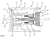
- a gas turbine engine is generally indicated at 10, having a principal and rotational axis 11.
- the engine 10 comprises, in axial flow series, an air intake 12, a propulsive fan 13, an intermediate pressure compressor 14, a high-pressure compressor 15, combustion equipment 16, a high-pressure turbine 17, and intermediate pressure turbine 18, a low-pressure turbine 19 and an exhaust nozzle 20.
- a nacelle 49 generally surrounds the engine 10 and defines both the intake 12 and the exhaust nozzle 20.
- the gas turbine engine 10 works in the conventional manner so that air entering the intake 12 is accelerated by the fan 13 to produce two air flows: a first air flow A into the intermediate pressure compressor 14 and a second air flow B which passes through a bypass duct defined by an internal space between a radially inner side of the engine nacelle 49 and a radially outer side of a core nacelle 50 to provide propulsive thrust.
- the intermediate pressure compressor 14 compresses the air flow directed into it before delivering that air to the high pressure compressor 15 where further compression takes place.
- a ratio of air entering the engine core (i.e. the intermediate pressure compressor 14) to air bypassing the core defines an engine bypass ratio (i.e. mass flow of air flow B divided by mass flow of air flow A).
- the bypass ratio is approximately 10. It has been found that at bypass ratios of approximately 10 or greater, the invention is particularly effective, though it will be understood that the invention is also applicable to engines having lower bypass ratios.
- the compressed air exhausted from the high-pressure compressor 15 is directed into the combustion equipment 16 where it is mixed with fuel and the mixture combusted.
- the resultant hot combustion products then expand through, and thereby drive the high, intermediate and low-pressure turbines 17, 18, 19 before being exhausted through the nozzle 20 to provide additional propulsive thrust.
- the high 17, intermediate 18 and low 19 pressure turbines drive respectively the high pressure compressor 15, intermediate pressure compressor 14 and fan 13, each by suitable interconnecting shafts.
- the compressors 14, 15, combustor 16 and turbines 17, 18, 19 are housed within the core nacelle 50.
- the core nacelle 50 defines a core inlet 38 at an axially forward end, and a core exhaust 23 at an axially rearward end.
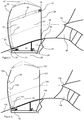
- FIG. 2 shows a first fan assembly.
- the fan 13 comprises a plurality of rotor blades 21 which radially project from the hub 22.
- the hub 22 and fan blades 21 together for a fan assembly.
- the hub 22 comprises a generally conical outer surface, which increases in diameter from a tip 23 at an axially forward end of the engine 10, to a maximum diameter adjacent the core inlet 38.
- Each fan blade 21 comprises a pressure surface 23, a suction surface 40 (shown in figure 6 ) on an opposite side, a leading edge 24, a trailing edge 25, a root 26 and a tip 27.
- the blade 21 extends generally radially from the root 26 to the tip 27. A distance between the root 26 and tip 27 defines a span of the blade 21.
- a distance between the leading and trailing edges 24, 25 defines a chord of the blade 21.
- the blade 21 is of superplastically formed, diffusion bonded construction, having a hollow interior provided with a warren girder construction, as described for example in European patent application EP 1092485 .
- the hub 22 is mounted to a low pressure shaft 28, which is in turn attached to the low pressure turbine 19. Consequently, the hub 22 is driven by the low pressure turbine 19.
- the blades 21 are each attached to a fan disc 28 by a fir tree mounting arrangement 29.
- the fan disc 28 is in turn attached to the hub 22, such that they rotate together.
- the hub 22 comprises a first inlet aperture 30 provided on an external, radially outer surface thereon.
- the inlet aperture 30 extends through the external surface of the hub 22 into the hollow exterior therein.
- the inlet aperture 30 communicated with a passage 31 provided in the blade 21.
- the passage 31 extends from a radially inner end radially inwardly of the aerodynamic root 26, and radially outwardly of the fir tree mounting arrangement 29 within a hollow interior 53 of the blade 21.
- the passage 31 extends generally radially outwardly from the inlet 30 part way along the span of the blade 21.
- the passage 31 comprises a leading edge portion 32 which extends in a generally radial direction, adjacent the leading edge 24 of the blade 21.
- the passage 31 further comprises a generally chordwise portion 33, which extends from a radially outer end of the leading edge portion 32 in a generally chordwise direction, toward the trailing edge 25, though the chordwise portion 33 may still extend in a direction having a radial component.
- the chordwise portion 33 extends to an outlet 34 located adjacent the trailing edge 25 at a radial position adjacent the tip 27.
- the outlet 34 communicates with the main fan flow.
- the outlet 34 comprises a plurality of holes 35.
- the outlet 34 is positioned radially outwardly of the inlet 30, and is in fluid communication with the passage 31 within the blade 21, and the inlet aperture 30. Consequently, the rotation of the blade 21 imparts centrifugal forces on the air within the passage 31, thereby raising the pressure of the air as the blade 21 rotates. Consequently, air is drawn in through the inlet 30, and exhausted at the outlet 34 via the passage 31.
- the outlet 34 is provided at a radial position such that the static pressure of the airflow emerging from the passage 31 at the outlet 34 exceeds the static pressure of the external fluid flow generated by the fan 13 at that radial position. As the skilled person will appreciate, this will depend on design details of the fan blade 21, and principally on the fan pressure ratio and fan rotational speed.
- a propulsive fan 13 for a passenger airliner may have a diameter D of 2.5m, a hub to tip ratio HTR of 0.3, and operate at a tip relative Mach number M rel_tip of 1.3 with an axial Mach number M ax of 0.6.
- the static temperature T and pressure P may be 240K and 28150Pa respectively, and the specific heat at constant pressure c p may be 1005 J/kg/K.
- the gas constant R for air is 287 J/kg/K, which gives the ratio of specific heats at constant pressure and volume y as 1.4.
- the fan 13 would typically produce a pressure ratio of between 1.3 and 1.6.
- a design choice must be made as to what radial position along the blade 21 the outlet 34 will be provided.
- T 0 1 T 1 1 + ⁇ ⁇ 1 2 M ax 2 257.3 K
- the total pressure is 73197Pa, so the total pressure rise is ⁇ 37000Pa.
- the pressure losses may be determined as follows.
- the 0.03% flow could be ejected at 30% of the blade height.
- the invention could be applied to different diameter fans.
- the flow would increase from 0.03% of full flow to 0.05% for the same diameter passages, in view of the increased pressure provided by the greater diameter.
- the flow would increase from 1.65% of full flow to 2.1%.
- 0.5% of the full flow could be provided using the whole internal area where the flow is ejected at the tip.
- increasing the speed will also increase the available flow.
- the hub 22 further comprises a second inlet aperture 36 located adjacent the trailing edge 25 of the blade 21.
- the second inlet aperture 36 communicates with the first inlet aperture 30 via an inlet manifold 37 defined by a hollow region within the blade 21 between the aerodynamic root 26 and the fir tree mounting arrangement 29. Consequently, air is drawn from both the area adjacent the leading edge 24 of the blade 21, and the area adjacent the trailing edge 25 of the blade 21. Consequently, secondary flow adjacent the outer surface of the hub 22 is withdrawn, and so the air ingested into the engine core has less turbulence, thereby improving core performance.
- Figure 3 shows a second fan assembly.
- the fan assembly is similar to that shown in figure 2 , with a passage 131 provided within a fan blade 121 in communication with first and second inlet apertures 130, 136 provided in a hub 122.
- the passage 131 comprises a generally radially extending leading edge portion 132, which terminates in an outlet 134.
- the outlet 134 is located adjacent a leading edge 124 of the blade 121, and again comprises a plurality of holes.
- the outlet 134 can be located at a position closer to the root (i.e. radially inwardly) compared to the outlet 34 of the embodiment shown in figure 2 .
- the outlet 134 is provided at a radial position corresponding to 30% of the fan blade 121 span (i.e. 30% of the distance from the aerodynamic root 126 to the tip 127). In view of the relatively high bypass ratio in this example engine, this corresponds to a radial position radially outward of the core nacelle 150, and so airflow from the outlet 134 is not ingested into the core inlet 138.
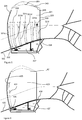
- Figure 4 shows a third fan assembly.
- the fan assembly is similar to that shown in figure 3 , with a passage 231 provided within a fan blade 221 in communication with first and second inlet apertures 230, 236 provided in a hub 222.
- the passage 231 comprises a generally radially extending leading edge portion 232, which terminates in an outlet 234.
- the outlet 134 is located adjacent a leading edge 224 of the blade 221.
- this embodiment differs from that of figure 3 in that the outlet 234 is provided at a tip 227 of the blade 221. In view of the position of the outlet 234 at the tip 227 of the blade 221, the pressure of the outlet flow is significantly greater at given conditions than the flow from the outlets 34, 134 of the embodiments shown in figure 2 and 3 .
- the outlet flow provides sealing flow at the tip 227, thereby preventing flow from leaking between blade passages at the tip, which would otherwise form secondary flows at the tip, i.e. further turbulent flow. Consequently, the fan efficiency can be increased, or the tip gap can be enlarged without detrimentally affecting fan efficiency.
- Figure 5 shows a fourth fan assembly.
- the fan assembly is similar to that shown in figure 4 , with a first passage 331 a provided within a fan blade 321 in communication with first and second inlet apertures 330, 336 provided in a hub 222 via an inlet manifold 337.
- the first passage 331 a extends in a generally radial direction part way along the span of the blade 321 adjacent a leading edge 324 of the blade 321.
- the assembly further comprises second through sixth passages 331b-f, which are also in communication with the inlet apertures 330, 336 via the inlet manifold 337.
- the passages 331b-f also extend in a generally radial direction, parallel to the first passage 331 a, and are spaced across the chord of the blade, with the sixth passage 331f being provided adjacent a trailing edge 325 of the blade 321, and the remaining passages 331b-e being spaced evenly in between. Due to the conical shape of the hub 322, a radially inner upstream end of the second passage 331 b is provided radially outwardly of the radial inner upstream end of the first passage 331 a. Similarly, the upstream ends of the third through sixth passages 331 c-f are provided further radially outwardly in ascending order.
- Each of the passages 331a-f terminates in a generally axially (i.e. chordally) extending outlet manifold 339 with which the passages 3311a-f are in fluid communication.
- the manifold 339 extends from substantially the leading edge 325 to the trailing edge 325 of the blade 321, and terminates in an outlet 335.
- the outlet 335 is located mid-way along the span of the blade 321, radially outwardly of the core inlet 38, adjacent the trailing edge 325. Consequently, the inlet apertures 330, 336 communicate with the outlet 335 via the inlet manifold 337, passages 331a-f and manifold 339 in flow sequence.
- the passages 331a-f may be formed by spaces defined by an internal warren structure within the hollow blade 321.
- the warren structure comprises web members 354 which extend between the pressure and suction surfaces 323, 340 within the blade, to thereby providing internal bracing.
- the manifold 339 may comprise chordally extending apertures provided within the web members 354, to thereby interconnect the spaces.
- Figure 6 shows a fifth fan assembly.
- the fan assembly is similar to that shown in figure 3 , with a passage 431 provided extending radially along a fan blade 421 in communication with first and second inlet apertures 430, 436 provided in a hub 422 via an inlet manifold 437.
- the passage 431 is provided in the form of a blister (i.e. an external projection) on a pressure surface 423 of the blade 421, which terminates in an outlet 435 at a radially outer end thereof. Consequently, the invention can be applied to solid blades such as carbon fibre reinforced composite (CFRP) blades, or to thin fan blade having insufficient internal thickness to accommodate the necessary passage diameter for low pressure losses.
- the passage 431 could extend within a hollow fan blade, with the pressure surface 423 having a projection at the location of the passage, to accommodate a larger diameter passage 431. Consequently, the invention can be provided on solid blades.
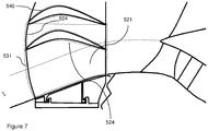
- FIG. 7 shows a sixth fan assembly.
- a passage 531 is provided extending through a blade 521.
- the passage 531 is again provided as a blister, and extends over both a pressure surface 523, and a suction surface 540, and wraps around a leading edge 524. Consequently, a passage having a large internal cross sectional area can be provided, without requiring a large external projection on the blade 521.
- Figure 8 shows a top view of the arrangement of figure 2 , looking down the span of the blade 21 from the tip 27 toward the root 26.
- Figure 8 shows two adjacent blades 21 a, 21 b of the fan assembly.
- An inter-blade passage 41 is defined by the circumferential space between the pressure surface 23 of blade 21 a and the suction surface 40 of blade 21 b. Further inter-blade passages are provided between adjacent blades 13 around the annulus of the hub 22.
- the inlet apertures 30, 36 each comprise circumferentially extending slots, which extend partly or wholly around the circumference of the hub 22 upstream and downstream respectively of the blades 13a, 13b.
- Figure 9 shows a top view of a seventh fan assembly, looking down the span of a blade 521.
- first 530, second 542 and third 543 inlet apertures are provided.
- Each of the apertures 530, 542, 543 communicates with a passage (not shown) similar to those of the previous embodiments, possibly via an inlet manifold (not shown).
- Each of the apertures 530, 542, 543 comprises a part circumferential slot.
- Each slot 530, 542, 543 is provided within an inter-blade passage 541 defined between adjacent blades 513a, 513b.
- the first slot 530 is provided adjacent the leading edge of the second blade 521 b, slightly downstream of a leading edge 524.
- the second slot 542 is provided slightly downstream of the first slot 530, adjacent the first blade 521 a.
- the third slot 543 is provided downstream of both of the first and second slots 530, 542 adjacent a mid-chord region of the second blade 521 b. Consequently, the third slot 443 captures secondary flow that has its origin on a streamline that does not pass over the first and second slots 530, 542.
- Figure 10 shows a top view of an eighth fan assembly, looking down the span of a blade 721.
- first 730, second 742, third 743, fourth 744 and fifth 745 inlet apertures are provided. Again, each aperture communicates with one or more passages such as those shown in figures 2 to 5 .
- Each aperture comprises a series of holes arranged in a row.
- the first aperture 730 is provided upstream of a leading edge 724 of a first blade 721 a, and extends generally circumferentially across part of an inter-blade passage 741.
- the second aperture 742 is provided within the inter-blade passage 741 at a mid-chord point adjacent the first blade 721 a and again extends generally part circumferentially.
- the third aperture 743 is provided downstream of the second blade adjacent the second blade 721 b, and extends part circumferentially.
- the fourth aperture 744 is provided adjacent the second blade 721 b downstream of the second aperture 744, extends generally axially, following the curvature of a suction side 740 of the second blade 721b.
- the fifth aperture 745 is provided adjacent the trailing edge 725 of the second blade 721 b, and extends generally part circumferentially.
- Figure 11 shows part of a ninth fan assembly, showing the cross sectional profile of inlet apertures 830, 836 provided in a hub 822, which again communicate with a passage (not shown) extending through a fan blade 821.
- the first aperture 830 comprises a first lip 846 at an upstream end, and a second lip 847 at a downstream end.
- a radially outer surface of the first lip 846 and a radially inner surface of the second lip 847 are shaped such that the inlet 830 extends into an inlet manifold 837 in a generally axial direction. Consequently, turning of the secondary flow as it enters the first inlet 830 is relatively low, thereby ensuring low pressure losses.
- the second aperture 836 comprises a first lip 848 at an upstream end, which projects radially inwardly toward the inlet manifold 837. Again, the lip 848 reduces turning of the flow into the inlet manifold 837.
- Figure 12 shows a tenth fan assembly.
- the assembly is similar to that of the first assembly shown in figures 2 , 8 and 11 .
- a second lip 947 of a first aperture 930 projects radially outwardly into the main flow path and thereby helps capture secondary airflow, such that a greater proportion of the boundary layer is ingested.
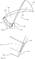
- FIGS 13 and 14 show a fan blade 1021 of an eleventh fan assembly.
- the fan blade 1021 comprises a pressure surface 1023, a suction surface 1040 on an opposite side, a leading edge 1024, a trailing edge 1025, a root 1026 and a tip 1027.
- the blade extends generally radially from the root 1026 to the tip 1027.
- the blade 1021 comprises a radially extending passage 1031 which extends from an inlet at the root 1026 to an outlet 1034 at the tip 1027.
- the passage 1031 extends within a hollow portion of the blade, adjacent the leading edge 1024.
- Figure 14 shows a close up of a tip region 1051 illustrated in figure 13 , and shows the outlet 1034 in more detail.
- the outlet 1034 emerges from the pressure side 1023 of the blade 1021, and is angled in a circumferential direction, such that the outlet 1034 is configured to direct air from the outlet 1034 away from the pressure side 1023 of the blade 1021, toward the suction side of an adjacent blade (not shown).
- the blade could be of carbon fibre construction, optionally comprising a metallic leading edge.
- the passage could be provided within a hollow metallic leading edge, or within a space defined by the join between the metallic leading edge and the main carbon fibre body.
Landscapes
- Engineering & Computer Science (AREA)
- Mechanical Engineering (AREA)
- General Engineering & Computer Science (AREA)
- Chemical & Material Sciences (AREA)
- Combustion & Propulsion (AREA)
- Architecture (AREA)
- Physics & Mathematics (AREA)
- Fluid Mechanics (AREA)
- Structures Of Non-Positive Displacement Pumps (AREA)
Applications Claiming Priority (1)
| Application Number | Priority Date | Filing Date | Title |
|---|---|---|---|
| GBGB1605323.3A GB201605323D0 (en) | 2016-03-30 | 2016-03-30 | Gas turbine engine fan assembly |
Publications (1)
| Publication Number | Publication Date |
|---|---|
| EP3225852A1 true EP3225852A1 (de) | 2017-10-04 |
Family
ID=56027575
Family Applications (1)
| Application Number | Title | Priority Date | Filing Date |
|---|---|---|---|
| EP17158641.5A Withdrawn EP3225852A1 (de) | 2016-03-30 | 2017-03-01 | Gebläseanordnung eines gasturbinentriebwerks |
Country Status (3)
| Country | Link |
|---|---|
| US (1) | US20170284422A1 (de) |
| EP (1) | EP3225852A1 (de) |
| GB (1) | GB201605323D0 (de) |
Families Citing this family (5)
| Publication number | Priority date | Publication date | Assignee | Title |
|---|---|---|---|---|
| JP7206129B2 (ja) * | 2019-02-26 | 2023-01-17 | 三菱重工業株式会社 | 翼及びこれを備えた機械 |
| GB202019219D0 (en) * | 2020-12-07 | 2021-01-20 | Rolls Royce Plc | Lean burn combustor |
| GB202019222D0 (en) * | 2020-12-07 | 2021-01-20 | Rolls Royce Plc | Lean burn combustor |
| US11655828B2 (en) | 2021-10-27 | 2023-05-23 | General Electric Company | Anti-icing systems and airfoils for a fan section of a turbine engine |
| US11988103B2 (en) | 2021-10-27 | 2024-05-21 | General Electric Company | Airfoils for a fan section of a turbine engine |
Citations (5)
| Publication number | Priority date | Publication date | Assignee | Title |
|---|---|---|---|---|
| FR592393A (fr) * | 1925-01-29 | 1925-08-01 | Hélice aérienne | |
| FR1002324A (fr) * | 1946-09-09 | 1952-03-05 | S. A. | Perfectionnements apportés aux turbo-machines à aubages, notamment aux compresseurs axiaux |
| US3735593A (en) * | 1970-02-11 | 1973-05-29 | Mini Of Aviat Supply In Her Br | Ducted fans as used in gas turbine engines of the type known as fan-jets |
| EP1878872A2 (de) * | 2006-07-11 | 2008-01-16 | General Electric Company | Turbofantriebwerk und Schaufeln dazu |
| GB2528116A (en) * | 2014-07-11 | 2016-01-13 | David Campbell Bannerman | Aircraft engine and wing assembly |
Family Cites Families (1)
| Publication number | Priority date | Publication date | Assignee | Title |
|---|---|---|---|---|
| US3572960A (en) * | 1969-01-02 | 1971-03-30 | Gen Electric | Reduction of sound in gas turbine engines |
-
2016
- 2016-03-30 GB GBGB1605323.3A patent/GB201605323D0/en not_active Ceased
-
2017
- 2017-03-01 US US15/446,337 patent/US20170284422A1/en not_active Abandoned
- 2017-03-01 EP EP17158641.5A patent/EP3225852A1/de not_active Withdrawn
Patent Citations (5)
| Publication number | Priority date | Publication date | Assignee | Title |
|---|---|---|---|---|
| FR592393A (fr) * | 1925-01-29 | 1925-08-01 | Hélice aérienne | |
| FR1002324A (fr) * | 1946-09-09 | 1952-03-05 | S. A. | Perfectionnements apportés aux turbo-machines à aubages, notamment aux compresseurs axiaux |
| US3735593A (en) * | 1970-02-11 | 1973-05-29 | Mini Of Aviat Supply In Her Br | Ducted fans as used in gas turbine engines of the type known as fan-jets |
| EP1878872A2 (de) * | 2006-07-11 | 2008-01-16 | General Electric Company | Turbofantriebwerk und Schaufeln dazu |
| GB2528116A (en) * | 2014-07-11 | 2016-01-13 | David Campbell Bannerman | Aircraft engine and wing assembly |
Also Published As
| Publication number | Publication date |
|---|---|
| GB201605323D0 (en) | 2016-05-11 |
| US20170284422A1 (en) | 2017-10-05 |
Similar Documents
| Publication | Publication Date | Title |
|---|---|---|
| US10436035B1 (en) | Fan design | |
| EP3369893B1 (de) | Gasturbinenmotorleitschaufeln | |
| EP3369891B1 (de) | Gasturbinenleitschaufeln | |
| US8523523B2 (en) | Cooling arrangements | |
| US9121368B2 (en) | Efficient, low pressure ratio propulsor for gas turbine engines | |
| US20220106965A1 (en) | Gas turbine engine airfoil | |
| CN109838307B (zh) | 燃气涡轮发动机 | |
| EP3225852A1 (de) | Gebläseanordnung eines gasturbinentriebwerks | |
| US11885233B2 (en) | Turbine engine with airfoil having high acceleration and low blade turning | |
| EP2685065A2 (de) | Gasturbinenmotor | |
| US11073108B2 (en) | Louvre offtake arrangement | |
| CN108952824A (zh) | 用于前缘辅助涡轮机静叶的方法和系统 | |
| CN111322158A (zh) | 用于气体涡轮引擎的冰晶体防护 | |
| US11732603B2 (en) | Ice crystal protection for a gas turbine engine | |
| US9752439B2 (en) | Gas turbine engine airfoil | |
| US12305535B2 (en) | Turbine engine having a compressor with an inducer | |
| EP3828385A2 (de) | Fan einer turbofan | |
| EP4343115B1 (de) | Schaufel für ein triebwerk mit einem schlitz | |
| US12428962B1 (en) | Gas turbine engine with acoustic spacing of the fan blades and outlet guide vanes | |
| US20250320833A1 (en) | Gas turbine engine | |
| EP4353948A1 (de) | Schaufelblatt für einen gasturbinenmotor | |
| EP4144960A1 (de) | Strömungmaschine für ein flugzeugtriebwerk und flugzeugtriebwerk | |
| US11326459B2 (en) | Blade for a gas turbine engine |
Legal Events
| Date | Code | Title | Description |
|---|---|---|---|
| PUAI | Public reference made under article 153(3) epc to a published international application that has entered the european phase |
Free format text: ORIGINAL CODE: 0009012 |
|
| STAA | Information on the status of an ep patent application or granted ep patent |
Free format text: STATUS: THE APPLICATION HAS BEEN PUBLISHED |
|
| AK | Designated contracting states |
Kind code of ref document: A1 Designated state(s): AL AT BE BG CH CY CZ DE DK EE ES FI FR GB GR HR HU IE IS IT LI LT LU LV MC MK MT NL NO PL PT RO RS SE SI SK SM TR |
|
| AX | Request for extension of the european patent |
Extension state: BA ME |
|
| STAA | Information on the status of an ep patent application or granted ep patent |
Free format text: STATUS: REQUEST FOR EXAMINATION WAS MADE |
|
| 17P | Request for examination filed |
Effective date: 20180322 |
|
| RBV | Designated contracting states (corrected) |
Designated state(s): AL AT BE BG CH CY CZ DE DK EE ES FI FR GB GR HR HU IE IS IT LI LT LU LV MC MK MT NL NO PL PT RO RS SE SI SK SM TR |
|
| RAP1 | Party data changed (applicant data changed or rights of an application transferred) |
Owner name: ROLLS-ROYCE PLC |
|
| STAA | Information on the status of an ep patent application or granted ep patent |
Free format text: STATUS: THE APPLICATION HAS BEEN WITHDRAWN |
|
| 18W | Application withdrawn |
Effective date: 20200603 |