EP3225862A1 - Glissière linéaire ayant un dispositif de lubrification - Google Patents
Glissière linéaire ayant un dispositif de lubrification Download PDFInfo
- Publication number
- EP3225862A1 EP3225862A1 EP16162574.4A EP16162574A EP3225862A1 EP 3225862 A1 EP3225862 A1 EP 3225862A1 EP 16162574 A EP16162574 A EP 16162574A EP 3225862 A1 EP3225862 A1 EP 3225862A1
- Authority
- EP
- European Patent Office
- Prior art keywords
- circulation
- dispenser
- smearing
- channels
- slide block
- Prior art date
- Legal status (The legal status is an assumption and is not a legal conclusion. Google has not performed a legal analysis and makes no representation as to the accuracy of the status listed.)
- Granted
Links
Images


Classifications
-
- F—MECHANICAL ENGINEERING; LIGHTING; HEATING; WEAPONS; BLASTING
- F16—ENGINEERING ELEMENTS AND UNITS; GENERAL MEASURES FOR PRODUCING AND MAINTAINING EFFECTIVE FUNCTIONING OF MACHINES OR INSTALLATIONS; THERMAL INSULATION IN GENERAL
- F16C—SHAFTS; FLEXIBLE SHAFTS; ELEMENTS OR CRANKSHAFT MECHANISMS; ROTARY BODIES OTHER THAN GEARING ELEMENTS; BEARINGS
- F16C33/00—Parts of bearings; Special methods for making bearings or parts thereof
- F16C33/30—Parts of ball or roller bearings
- F16C33/66—Special parts or details in view of lubrication
- F16C33/6603—Special parts or details in view of lubrication with grease as lubricant
- F16C33/6607—Retaining the grease in or near the bearing
- F16C33/6614—Retaining the grease in or near the bearing in recesses or cavities provided in retainers, races or rolling elements
-
- F—MECHANICAL ENGINEERING; LIGHTING; HEATING; WEAPONS; BLASTING
- F16—ENGINEERING ELEMENTS AND UNITS; GENERAL MEASURES FOR PRODUCING AND MAINTAINING EFFECTIVE FUNCTIONING OF MACHINES OR INSTALLATIONS; THERMAL INSULATION IN GENERAL
- F16C—SHAFTS; FLEXIBLE SHAFTS; ELEMENTS OR CRANKSHAFT MECHANISMS; ROTARY BODIES OTHER THAN GEARING ELEMENTS; BEARINGS
- F16C33/00—Parts of bearings; Special methods for making bearings or parts thereof
- F16C33/30—Parts of ball or roller bearings
- F16C33/66—Special parts or details in view of lubrication
- F16C33/6637—Special parts or details in view of lubrication with liquid lubricant
- F16C33/6659—Details of supply of the liquid to the bearing, e.g. passages or nozzles
- F16C33/6666—Details of supply of the liquid to the bearing, e.g. passages or nozzles from an oil bath in the bearing housing, e.g. by an oil ring or centrifugal disc
-
- F—MECHANICAL ENGINEERING; LIGHTING; HEATING; WEAPONS; BLASTING
- F16—ENGINEERING ELEMENTS AND UNITS; GENERAL MEASURES FOR PRODUCING AND MAINTAINING EFFECTIVE FUNCTIONING OF MACHINES OR INSTALLATIONS; THERMAL INSULATION IN GENERAL
- F16C—SHAFTS; FLEXIBLE SHAFTS; ELEMENTS OR CRANKSHAFT MECHANISMS; ROTARY BODIES OTHER THAN GEARING ELEMENTS; BEARINGS
- F16C29/00—Bearings for parts moving only linearly
- F16C29/04—Ball or roller bearings
- F16C29/06—Ball or roller bearings in which the rolling bodies circulate partly without carrying load
- F16C29/0602—Details of the bearing body or carriage or parts thereof, e.g. methods for manufacturing or assembly
- F16C29/0609—Details of the bearing body or carriage or parts thereof, e.g. methods for manufacturing or assembly of the ends of the bearing body or carriage where the rolling elements change direction, e.g. end caps
-
- F—MECHANICAL ENGINEERING; LIGHTING; HEATING; WEAPONS; BLASTING
- F16—ENGINEERING ELEMENTS AND UNITS; GENERAL MEASURES FOR PRODUCING AND MAINTAINING EFFECTIVE FUNCTIONING OF MACHINES OR INSTALLATIONS; THERMAL INSULATION IN GENERAL
- F16C—SHAFTS; FLEXIBLE SHAFTS; ELEMENTS OR CRANKSHAFT MECHANISMS; ROTARY BODIES OTHER THAN GEARING ELEMENTS; BEARINGS
- F16C29/00—Bearings for parts moving only linearly
- F16C29/04—Ball or roller bearings
- F16C29/06—Ball or roller bearings in which the rolling bodies circulate partly without carrying load
- F16C29/0602—Details of the bearing body or carriage or parts thereof, e.g. methods for manufacturing or assembly
- F16C29/0611—Details of the bearing body or carriage or parts thereof, e.g. methods for manufacturing or assembly of the return passages, i.e. the passages where the rolling elements do not carry load
-
- F—MECHANICAL ENGINEERING; LIGHTING; HEATING; WEAPONS; BLASTING
- F16—ENGINEERING ELEMENTS AND UNITS; GENERAL MEASURES FOR PRODUCING AND MAINTAINING EFFECTIVE FUNCTIONING OF MACHINES OR INSTALLATIONS; THERMAL INSULATION IN GENERAL
- F16C—SHAFTS; FLEXIBLE SHAFTS; ELEMENTS OR CRANKSHAFT MECHANISMS; ROTARY BODIES OTHER THAN GEARING ELEMENTS; BEARINGS
- F16C29/00—Bearings for parts moving only linearly
- F16C29/04—Ball or roller bearings
- F16C29/06—Ball or roller bearings in which the rolling bodies circulate partly without carrying load
- F16C29/0633—Ball or roller bearings in which the rolling bodies circulate partly without carrying load with a bearing body defining a U-shaped carriage, i.e. surrounding a guide rail or track on three sides
- F16C29/0635—Ball or roller bearings in which the rolling bodies circulate partly without carrying load with a bearing body defining a U-shaped carriage, i.e. surrounding a guide rail or track on three sides whereby the return paths are provided as bores in a main body of the U-shaped carriage, e.g. the main body of the U-shaped carriage is a single part with end caps provided at each end
- F16C29/0638—Ball or roller bearings in which the rolling bodies circulate partly without carrying load with a bearing body defining a U-shaped carriage, i.e. surrounding a guide rail or track on three sides whereby the return paths are provided as bores in a main body of the U-shaped carriage, e.g. the main body of the U-shaped carriage is a single part with end caps provided at each end with balls
- F16C29/0642—Ball or roller bearings in which the rolling bodies circulate partly without carrying load with a bearing body defining a U-shaped carriage, i.e. surrounding a guide rail or track on three sides whereby the return paths are provided as bores in a main body of the U-shaped carriage, e.g. the main body of the U-shaped carriage is a single part with end caps provided at each end with balls with four rows of balls
- F16C29/0647—Ball or roller bearings in which the rolling bodies circulate partly without carrying load with a bearing body defining a U-shaped carriage, i.e. surrounding a guide rail or track on three sides whereby the return paths are provided as bores in a main body of the U-shaped carriage, e.g. the main body of the U-shaped carriage is a single part with end caps provided at each end with balls with four rows of balls with load directions in X-arrangement
-
- F—MECHANICAL ENGINEERING; LIGHTING; HEATING; WEAPONS; BLASTING
- F16—ENGINEERING ELEMENTS AND UNITS; GENERAL MEASURES FOR PRODUCING AND MAINTAINING EFFECTIVE FUNCTIONING OF MACHINES OR INSTALLATIONS; THERMAL INSULATION IN GENERAL
- F16C—SHAFTS; FLEXIBLE SHAFTS; ELEMENTS OR CRANKSHAFT MECHANISMS; ROTARY BODIES OTHER THAN GEARING ELEMENTS; BEARINGS
- F16C29/00—Bearings for parts moving only linearly
- F16C29/04—Ball or roller bearings
- F16C29/06—Ball or roller bearings in which the rolling bodies circulate partly without carrying load
- F16C29/0633—Ball or roller bearings in which the rolling bodies circulate partly without carrying load with a bearing body defining a U-shaped carriage, i.e. surrounding a guide rail or track on three sides
- F16C29/0652—Ball or roller bearings in which the rolling bodies circulate partly without carrying load with a bearing body defining a U-shaped carriage, i.e. surrounding a guide rail or track on three sides whereby the return paths are at least partly defined by separate parts, e.g. covers attached to the legs of the main body of the U-shaped carriage
- F16C29/0654—Ball or roller bearings in which the rolling bodies circulate partly without carrying load with a bearing body defining a U-shaped carriage, i.e. surrounding a guide rail or track on three sides whereby the return paths are at least partly defined by separate parts, e.g. covers attached to the legs of the main body of the U-shaped carriage with balls
- F16C29/0659—Ball or roller bearings in which the rolling bodies circulate partly without carrying load with a bearing body defining a U-shaped carriage, i.e. surrounding a guide rail or track on three sides whereby the return paths are at least partly defined by separate parts, e.g. covers attached to the legs of the main body of the U-shaped carriage with balls with four rows of balls
- F16C29/0661—Ball or roller bearings in which the rolling bodies circulate partly without carrying load with a bearing body defining a U-shaped carriage, i.e. surrounding a guide rail or track on three sides whereby the return paths are at least partly defined by separate parts, e.g. covers attached to the legs of the main body of the U-shaped carriage with balls with four rows of balls with load directions in O-arrangement
-
- F—MECHANICAL ENGINEERING; LIGHTING; HEATING; WEAPONS; BLASTING
- F16—ENGINEERING ELEMENTS AND UNITS; GENERAL MEASURES FOR PRODUCING AND MAINTAINING EFFECTIVE FUNCTIONING OF MACHINES OR INSTALLATIONS; THERMAL INSULATION IN GENERAL
- F16C—SHAFTS; FLEXIBLE SHAFTS; ELEMENTS OR CRANKSHAFT MECHANISMS; ROTARY BODIES OTHER THAN GEARING ELEMENTS; BEARINGS
- F16C33/00—Parts of bearings; Special methods for making bearings or parts thereof
- F16C33/30—Parts of ball or roller bearings
- F16C33/66—Special parts or details in view of lubrication
- F16C33/6603—Special parts or details in view of lubrication with grease as lubricant
- F16C33/6607—Retaining the grease in or near the bearing
- F16C33/6611—Retaining the grease in or near the bearing in a porous or resinous body, e.g. a cage impregnated with the grease
-
- F—MECHANICAL ENGINEERING; LIGHTING; HEATING; WEAPONS; BLASTING
- F16—ENGINEERING ELEMENTS AND UNITS; GENERAL MEASURES FOR PRODUCING AND MAINTAINING EFFECTIVE FUNCTIONING OF MACHINES OR INSTALLATIONS; THERMAL INSULATION IN GENERAL
- F16C—SHAFTS; FLEXIBLE SHAFTS; ELEMENTS OR CRANKSHAFT MECHANISMS; ROTARY BODIES OTHER THAN GEARING ELEMENTS; BEARINGS
- F16C33/00—Parts of bearings; Special methods for making bearings or parts thereof
- F16C33/30—Parts of ball or roller bearings
- F16C33/66—Special parts or details in view of lubrication
- F16C33/6603—Special parts or details in view of lubrication with grease as lubricant
- F16C33/6607—Retaining the grease in or near the bearing
- F16C33/6618—Retaining the grease in or near the bearing in a reservoir in the sealing means
-
- F—MECHANICAL ENGINEERING; LIGHTING; HEATING; WEAPONS; BLASTING
- F16—ENGINEERING ELEMENTS AND UNITS; GENERAL MEASURES FOR PRODUCING AND MAINTAINING EFFECTIVE FUNCTIONING OF MACHINES OR INSTALLATIONS; THERMAL INSULATION IN GENERAL
- F16C—SHAFTS; FLEXIBLE SHAFTS; ELEMENTS OR CRANKSHAFT MECHANISMS; ROTARY BODIES OTHER THAN GEARING ELEMENTS; BEARINGS
- F16C33/00—Parts of bearings; Special methods for making bearings or parts thereof
- F16C33/30—Parts of ball or roller bearings
- F16C33/66—Special parts or details in view of lubrication
- F16C33/6637—Special parts or details in view of lubrication with liquid lubricant
- F16C33/664—Retaining the liquid in or near the bearing
- F16C33/6651—Retaining the liquid in or near the bearing in recesses or cavities provided in retainers, races or rolling elements
-
- F—MECHANICAL ENGINEERING; LIGHTING; HEATING; WEAPONS; BLASTING
- F16—ENGINEERING ELEMENTS AND UNITS; GENERAL MEASURES FOR PRODUCING AND MAINTAINING EFFECTIVE FUNCTIONING OF MACHINES OR INSTALLATIONS; THERMAL INSULATION IN GENERAL
- F16C—SHAFTS; FLEXIBLE SHAFTS; ELEMENTS OR CRANKSHAFT MECHANISMS; ROTARY BODIES OTHER THAN GEARING ELEMENTS; BEARINGS
- F16C33/00—Parts of bearings; Special methods for making bearings or parts thereof
- F16C33/30—Parts of ball or roller bearings
- F16C33/66—Special parts or details in view of lubrication
- F16C33/6637—Special parts or details in view of lubrication with liquid lubricant
- F16C33/6659—Details of supply of the liquid to the bearing, e.g. passages or nozzles
-
- F—MECHANICAL ENGINEERING; LIGHTING; HEATING; WEAPONS; BLASTING
- F16—ENGINEERING ELEMENTS AND UNITS; GENERAL MEASURES FOR PRODUCING AND MAINTAINING EFFECTIVE FUNCTIONING OF MACHINES OR INSTALLATIONS; THERMAL INSULATION IN GENERAL
- F16C—SHAFTS; FLEXIBLE SHAFTS; ELEMENTS OR CRANKSHAFT MECHANISMS; ROTARY BODIES OTHER THAN GEARING ELEMENTS; BEARINGS
- F16C2212/00—Natural materials, i.e. based on animal or plant products such as leather, wood or cotton or extracted therefrom, e.g. lignin
- F16C2212/08—Woven, unwoven fabrics, e.g. felt
Definitions
- the present invention relates to a linear slide, and more particularly to a linear slide having a lubricating device.
- a linear slide and a ball screw are commonly used in precision transmission devices. Through a movable member, the linear slide and the ball screw can be displaced relative to a long axle. In order to improve the lubrication between the movable member and the long axle, a lubricating device is provided between the movable member and the long axle.
- a long axle of a conventional linear slide (10) is provided with an oil tank (12).
- the oil tank (12) is filled with lubricant.
- a smearing structure (14) is provided between a movable member (13) slidably disposed on the long axle (11) and the inner side of the oil tank (12).
- a connector (15) having an oil guide member (151) is provided between the smearing structure (14) and the oil tank (12).
- the oil guide member (151) of the connector (15) absorbs the lubricant in the oil tank (12) and dispenses the lubricant to the smearing structure (14) to lubricate the rolling groove of the long axle (11).
- the oil guide member (151) of the linear slide (10) is made of wool felt.
- the lubricant is delivered by capillarity. On condition that the oil tank (12) has the lubricant, the oil guide member (151) will guide out the lubricant continuously. No matter whether the movable member (13) is moved or not, the lubricant is guided out continuously. This may cause a leak of oil. Accordingly, the inventor of the present invention has devoted himself based on his many years of practical experiences to solve these problems.
- the primary object of the present invention is to provide a lubricating device able to control the outflow of oil, without lengthening a slide block module of a linear slide.
- the linear slide having a lubricating device of the present invention comprises a long axle, a slide block module, a smearing member, and a dispenser.
- the long axle is an elongate structure extending in a direction defined as an axial direction. Two sides of the long axle are formed with rolling grooves in the axial direction.
- the slide block module is slidably disposed on the long axle, and comprises a slide block and two circulation members.
- the slide block has a rolling trough therein corresponding to the rolling grooves. The rolling grooves and the rolling trough form a load route.
- the slide block further has a plurality of circulation holes disposed in the axial direction and penetrating two end surfaces thereof.
- the two circulation members are disposed at the two end surfaces of the slide block, respectively.
- the two circulation members each have a plurality of circulation channels with two ends to communicate with the load route and the circulation holes, respectively.
- the load route, the circulation holes, and the circulation channels form a circulation route.
- the circulation route is adapted to receive a rolling member therein.
- At least one of the circulation members has an oil storage trough and a retaining through hole.
- the oil storage trough, the circulation channels, and the retaining through hole are in communication with each other.
- the oil storage trough is filled with lubricant.
- the smearing member is disposed in the retaining through hole.
- the dispenser covers the smearing member. The dispenser absorbs the lubricant and dispenses the lubricant to the smearing member. When the rolling member passes through the circulation channels, the rolling member is in contact with the smearing member.
- the smearing member and the dispenser are made of wool felt.
- the wool felt of the smearing member has a density different from that of the dispenser.
- each circulation member comprises a main body and a lid.
- the main body has the oil storage trough, the retaining through hole, and second half channels.
- the lid has first half channels corresponding to the second half channels. The first half channels and the second half channels form the circulation channels.
- the smearing member corresponds in shape to the retaining through hole.
- each circulation member is provided with a positioning cover.
- the positioning cover is adapted to cover the oil storage trough and press and secure the dispenser.
- the smearing member won't directly absorb the lubricant to decrease the amount of the outflow of the lubricant.
- the smearing member must be contact with the rolling member for the lubricant to flow out.
- the wool felt of the smearing member has a density different from that of the dispenser.
- the density of the wool felt of the smearing member is greater than that of dispenser, and vice versa. In this way, the amount of the lubricant from the smearing member can be controlled.
- the differential of the density of the wool felt can be adjusted according to different industries.
- the present invention can enhance the practicability of the lubricating device.
- the oil storage space uses the free space of the main body of the circulation member, without an additional oil tank to store the lubricant, so the length of the slide block module is not changed.
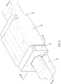
- a linear slide having a lubricating device in accordance with a preferred embodiment of the present invention comprises a long axle (1), a slide block module, a smearing member (4), and a dispenser (5).
- the long axle (1) is an elongate structure extending in a direction defined as an axial direction (X). Two sides of the long axle (1) are formed with rolling grooves (11) in the axial direction (X).
- the slide block module is slidably disposed on the long axle (1) and comprises a slide block (2) and two circulation members (3).
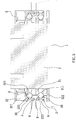
- the slide block (2) has a rolling trough (21) therein corresponding to the rolling grooves (11).
- the rolling grooves (11) and the rolling trough (21) form a load route.
- the slide block (2) further has a plurality of circulation holes (22) disposed in the axial direction (X) and penetrating two end surfaces (23) thereof.
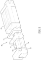
- the two circulation members (3) are disposed at the two end surfaces (23) of the slide block (2), respectively.
- the two circulation members (3) each have a plurality of circulation channels (30) with two ends to communicate with the load route and the circulation holes (22) respectively.
- the load route, the circulation holes (22), and the circulation channels (30) form a circulation route.
- the circulation route is adapted to receive a rolling member (9) therein.
- At least one of the circulation members (3) has an oil storage trough (321) and a retaining through hole (323).
- the oil storage trough (321), the circulation channels (30), and the retaining through hole (323) are in communication with each other.
- each circulation member (3) comprises a main body (32) and a lid (31).
- the main body (32) has the oil storage trough (321), the retaining through hole (323), and second half channels (322).
- the lid (31) has first half channels (311) corresponding to the second half channels (322).
- the first half channels (311) and the second half channels (322) form the circulation channels (30).
- the smearing member (4) is disposed in the retaining through hole (323).
- the smearing member (4) corresponds in shape to the retaining through hole (323), such that the smearing member (4) can be accommodated in the retaining through hole (323).
- the dispenser (5) is to cover the smearing member (4).
- Each circulation member (30) is provided with a positioning cover (6).
- the positioning cover (6) is adapted to cover the oil storage trough (321) and press and secure the dispenser (5).
- the dispenser (5) absorbs the lubricant and dispenses the lubricant to the smearing member (4).
- the rolling member (9) passes through the circulation channels (30)
- the rolling member (9) gets contact with the smearing member (4) and is lubricated with the lubricant.
- a film of oil is formed between the rolling member (9) and the rolling groove so as to prolong the service life of the linear slide.
- the smearing member (4) and the dispenser (5) are made of wool felt.
- the wool felt of the smearing member (4) has a density different from that of the dispenser (5).
- the density of the wool felt can be changed depending on the environment of use of various linear slides.
- the present invention is a.
Landscapes
- Engineering & Computer Science (AREA)
- General Engineering & Computer Science (AREA)
- Mechanical Engineering (AREA)
- Bearings For Parts Moving Linearly (AREA)
Priority Applications (4)
| Application Number | Priority Date | Filing Date | Title |
|---|---|---|---|
| EP16162574.4A EP3225862B1 (fr) | 2016-03-29 | 2016-03-29 | Glissière linéaire ayant un dispositif de lubrification |
| ES16162574.4T ES2693385T3 (es) | 2016-03-29 | 2016-03-29 | Corredera lineal que tiene dispositivo de lubricación |
| JP2016085826A JP6340381B2 (ja) | 2016-03-29 | 2016-04-22 | 潤滑装置を備えたリニアガイド |
| US15/144,828 US9797450B1 (en) | 2016-03-29 | 2016-05-03 | Linear guide with lubrication device |
Applications Claiming Priority (3)
| Application Number | Priority Date | Filing Date | Title |
|---|---|---|---|
| EP16162574.4A EP3225862B1 (fr) | 2016-03-29 | 2016-03-29 | Glissière linéaire ayant un dispositif de lubrification |
| JP2016085826A JP6340381B2 (ja) | 2016-03-29 | 2016-04-22 | 潤滑装置を備えたリニアガイド |
| US15/144,828 US9797450B1 (en) | 2016-03-29 | 2016-05-03 | Linear guide with lubrication device |
Publications (2)
| Publication Number | Publication Date |
|---|---|
| EP3225862A1 true EP3225862A1 (fr) | 2017-10-04 |
| EP3225862B1 EP3225862B1 (fr) | 2018-08-22 |
Family
ID=68535977
Family Applications (1)
| Application Number | Title | Priority Date | Filing Date |
|---|---|---|---|
| EP16162574.4A Active EP3225862B1 (fr) | 2016-03-29 | 2016-03-29 | Glissière linéaire ayant un dispositif de lubrification |
Country Status (4)
| Country | Link |
|---|---|
| US (1) | US9797450B1 (fr) |
| EP (1) | EP3225862B1 (fr) |
| JP (1) | JP6340381B2 (fr) |
| ES (1) | ES2693385T3 (fr) |
Cited By (2)
| Publication number | Priority date | Publication date | Assignee | Title |
|---|---|---|---|---|
| CN110319119A (zh) * | 2018-03-29 | 2019-10-11 | 罗伯特·博世有限公司 | 润滑单元、引导机构以及用于引导机构的方法 |
| CN115306824A (zh) * | 2021-04-02 | 2022-11-08 | Smc 株式会社 | 线性引导件 |
Families Citing this family (6)
| Publication number | Priority date | Publication date | Assignee | Title |
|---|---|---|---|---|
| WO2019109269A1 (fr) * | 2017-12-06 | 2019-06-13 | 舍弗勒技术股份两合公司 | Dispositif d'étanchéité de partie d'extrémité et système de guidage linéaire |
| US12187550B2 (en) * | 2019-04-23 | 2025-01-07 | Yamaha Hatsudoki Kabushiki Kaisha | Linear conveyor system, a control method for a linear conveyor system, a control program for a linear conveyor system and a recording medium |
| JP7083964B2 (ja) * | 2019-04-23 | 2022-06-13 | ヤマハ発動機株式会社 | リニアコンベアシステム、リニアコンベアシステムの制御方法、リニアコンベアシステムの制御プログラムおよび記録媒体 |
| KR102270914B1 (ko) * | 2020-03-06 | 2021-06-30 | 하이윈 테크놀로지스 코포레이션 | 리니어 트랜스미션 장치 |
| WO2022088059A1 (fr) * | 2020-10-30 | 2022-05-05 | 缪童宇 | Mécanisme de fixation de module de grue |
| DE102021103479A1 (de) * | 2021-02-15 | 2022-08-18 | Krones Aktiengesellschaft | Vorrichtung zum Behandeln von Behältnissen mit Linearantrieb, sowie Linearantrieb |
Citations (5)
| Publication number | Priority date | Publication date | Assignee | Title |
|---|---|---|---|---|
| EP0950465A2 (fr) * | 1998-04-16 | 1999-10-20 | Thk Co. Ltd. | Dispositif d'alimentation de lubrifiant et appareil de mouvement linéaire l'utilisant |
| DE102006056805B3 (de) * | 2006-12-01 | 2008-07-10 | Hiwin Technologies Corp. | Ölbehälter für eine Linearführung mit veränderbarer Montagerichtung |
| US20130108194A1 (en) * | 2011-10-28 | 2013-05-02 | Nippon Thompson Co., Ltd. | Linear motion guide unit using balls |
| US20150071576A1 (en) * | 2013-09-11 | 2015-03-12 | Nippon Thompson Co., Ltd. | Linear motion guide unit |
| US20150086140A1 (en) * | 2013-09-25 | 2015-03-26 | Nippon Thompson Co., Ltd. | Linear motion guide unit with lubricating member |
Family Cites Families (21)
| Publication number | Priority date | Publication date | Assignee | Title |
|---|---|---|---|---|
| JP4070265B2 (ja) * | 1997-07-01 | 2008-04-02 | Thk株式会社 | 直線案内装置 |
| JP4111585B2 (ja) * | 1998-04-16 | 2008-07-02 | Thk株式会社 | 潤滑油供給装置及びこれを用いた直線運動装置 |
| JP3980778B2 (ja) * | 1998-11-06 | 2007-09-26 | 日本トムソン株式会社 | 直動案内ユニット |
| JP4035241B2 (ja) * | 1998-11-13 | 2008-01-16 | 日本トムソン株式会社 | 潤滑装置を備えた直動案内ユニット |
| US20030164264A1 (en) * | 2002-03-04 | 2003-09-04 | Bing-Hung Luo | Structure for linear guideway |
| DE10332922A1 (de) * | 2003-07-19 | 2005-02-03 | Ina-Schaeffler Kg | Führungswagen eines Linearwälzlagers |
| JP4261380B2 (ja) * | 2004-02-05 | 2009-04-30 | 上銀科技股▲分▼有限公司 | 自主潤滑システム付きリニアガイド |
| JP2005256901A (ja) * | 2004-03-10 | 2005-09-22 | Abba Linear Tech Co Ltd | 自己潤滑型注油器 |
| JP2005337451A (ja) * | 2004-05-28 | 2005-12-08 | Nsk Ltd | 直動案内軸受装置 |
| DE102004036529A1 (de) * | 2004-07-28 | 2006-03-23 | Bosch Rexroth Mechatronics Gmbh | Linearvorrichtung |
| JP2006057795A (ja) * | 2004-08-23 | 2006-03-02 | Nsk Ltd | 直動案内軸受装置 |
| JP4521305B2 (ja) * | 2005-03-23 | 2010-08-11 | 日本トムソン株式会社 | 直動案内ユニット |
| JP4685723B2 (ja) * | 2005-09-06 | 2011-05-18 | 日本トムソン株式会社 | 直動案内ユニット |
| US7543684B2 (en) * | 2005-11-01 | 2009-06-09 | Hiwin Technologies Corp. | Oil-conducting apparatus for a linear motion system |
| US7556430B2 (en) * | 2006-12-27 | 2009-07-07 | Hiwin Technologies Corp. | Linear motion guide apparatus having lubricating device |
| DE102007013945A1 (de) * | 2007-03-23 | 2008-09-25 | Schaeffler Kg | Schmiervorrichtung für ein Linearwälzlager |
| US7614790B2 (en) * | 2007-05-15 | 2009-11-10 | Hiwin Technologies Corp. | Linear driving device with a self-lubricating assembly |
| JP5685450B2 (ja) * | 2011-01-27 | 2015-03-18 | 日本トムソン株式会社 | 潤滑寿命を延長する直動転がり案内ユニット |
| US8721180B2 (en) * | 2012-09-19 | 2014-05-13 | Hiwin Technologies Corp. | Lubricating structure for linear motion guide apparatus |
| US9222515B2 (en) * | 2014-02-19 | 2015-12-29 | Hiwin Technologies Corp. | Lubricating structure for linear motion guide apparatus |
| JP6439333B2 (ja) * | 2014-09-12 | 2018-12-19 | 日本精工株式会社 | 転がり軸受案内装置 |
-
2016
- 2016-03-29 EP EP16162574.4A patent/EP3225862B1/fr active Active
- 2016-03-29 ES ES16162574.4T patent/ES2693385T3/es active Active
- 2016-04-22 JP JP2016085826A patent/JP6340381B2/ja active Active
- 2016-05-03 US US15/144,828 patent/US9797450B1/en active Active
Patent Citations (5)
| Publication number | Priority date | Publication date | Assignee | Title |
|---|---|---|---|---|
| EP0950465A2 (fr) * | 1998-04-16 | 1999-10-20 | Thk Co. Ltd. | Dispositif d'alimentation de lubrifiant et appareil de mouvement linéaire l'utilisant |
| DE102006056805B3 (de) * | 2006-12-01 | 2008-07-10 | Hiwin Technologies Corp. | Ölbehälter für eine Linearführung mit veränderbarer Montagerichtung |
| US20130108194A1 (en) * | 2011-10-28 | 2013-05-02 | Nippon Thompson Co., Ltd. | Linear motion guide unit using balls |
| US20150071576A1 (en) * | 2013-09-11 | 2015-03-12 | Nippon Thompson Co., Ltd. | Linear motion guide unit |
| US20150086140A1 (en) * | 2013-09-25 | 2015-03-26 | Nippon Thompson Co., Ltd. | Linear motion guide unit with lubricating member |
Cited By (2)
| Publication number | Priority date | Publication date | Assignee | Title |
|---|---|---|---|---|
| CN110319119A (zh) * | 2018-03-29 | 2019-10-11 | 罗伯特·博世有限公司 | 润滑单元、引导机构以及用于引导机构的方法 |
| CN115306824A (zh) * | 2021-04-02 | 2022-11-08 | Smc 株式会社 | 线性引导件 |
Also Published As
| Publication number | Publication date |
|---|---|
| US20170321752A1 (en) | 2017-11-09 |
| ES2693385T3 (es) | 2018-12-11 |
| US9797450B1 (en) | 2017-10-24 |
| JP6340381B2 (ja) | 2018-06-06 |
| JP2017194137A (ja) | 2017-10-26 |
| EP3225862B1 (fr) | 2018-08-22 |
Similar Documents
| Publication | Publication Date | Title |
|---|---|---|
| EP3225862B1 (fr) | Glissière linéaire ayant un dispositif de lubrification | |
| US7614790B2 (en) | Linear driving device with a self-lubricating assembly | |
| US10774872B2 (en) | Linear guide | |
| JP6445788B2 (ja) | 直動転がり案内ユニット | |
| EP1835187A1 (fr) | Dispositif de guidage de mouvement et methode pour le lubrifier | |
| US7044641B2 (en) | Roller type linear guideway | |
| US9234544B2 (en) | Lubricating structure for linear motion guide apparatus | |
| US20110170809A1 (en) | Automatic lubrication structure of slide mechanism | |
| US20150184696A1 (en) | Deflecting device for ball spline device | |
| KR101789606B1 (ko) | 윤활 유닛을 구비한 선형 동력 전달 장치 | |
| EP2080921A2 (fr) | Dispositif de lubrification pour un roulement | |
| JP2006105310A (ja) | 直動案内ユニット | |
| JP5550918B2 (ja) | 直動案内ユニット | |
| JP2006144840A (ja) | 直動案内ユニット | |
| CN104565034B (zh) | 具润滑结构的线性滑轨 | |
| JPH09303392A (ja) | 潤滑剤供給装置付き直動案内軸受装置 | |
| TWI596286B (zh) | Linear slide with lubrication | |
| KR102814203B1 (ko) | 다중 오일 챔버를 갖는 자체 윤활식 오일 탱크 | |
| JP6231750B2 (ja) | 案内装置及び案内装置ユニット | |
| JPH0754844A (ja) | 潤滑剤含有ポリマによる潤滑リニアガイド装置 | |
| CN110725860B (zh) | 线性滑轨及其端模块与润滑单元 | |
| CN107269694A (zh) | 具润滑装置的线性滑轨 | |
| JP6358943B2 (ja) | 運動案内装置 | |
| JP5799736B2 (ja) | リニアガイド | |
| JP2022158484A (ja) | リニアガイド |
Legal Events
| Date | Code | Title | Description |
|---|---|---|---|
| PUAI | Public reference made under article 153(3) epc to a published international application that has entered the european phase |
Free format text: ORIGINAL CODE: 0009012 |
|
| STAA | Information on the status of an ep patent application or granted ep patent |
Free format text: STATUS: REQUEST FOR EXAMINATION WAS MADE |
|
| 17P | Request for examination filed |
Effective date: 20161221 |
|
| AK | Designated contracting states |
Kind code of ref document: A1 Designated state(s): AL AT BE BG CH CY CZ DE DK EE ES FI FR GB GR HR HU IE IS IT LI LT LU LV MC MK MT NL NO PL PT RO RS SE SI SK SM TR |
|
| AX | Request for extension of the european patent |
Extension state: BA ME |
|
| GRAP | Despatch of communication of intention to grant a patent |
Free format text: ORIGINAL CODE: EPIDOSNIGR1 |
|
| STAA | Information on the status of an ep patent application or granted ep patent |
Free format text: STATUS: GRANT OF PATENT IS INTENDED |
|
| INTG | Intention to grant announced |
Effective date: 20180302 |
|
| RAP1 | Party data changed (applicant data changed or rights of an application transferred) |
Owner name: HIWIN TECHNOLOGIES CORP. |
|
| GRAS | Grant fee paid |
Free format text: ORIGINAL CODE: EPIDOSNIGR3 |
|
| GRAA | (expected) grant |
Free format text: ORIGINAL CODE: 0009210 |
|
| STAA | Information on the status of an ep patent application or granted ep patent |
Free format text: STATUS: THE PATENT HAS BEEN GRANTED |
|
| AK | Designated contracting states |
Kind code of ref document: B1 Designated state(s): AL AT BE BG CH CY CZ DE DK EE ES FI FR GB GR HR HU IE IS IT LI LT LU LV MC MK MT NL NO PL PT RO RS SE SI SK SM TR |
|
| REG | Reference to a national code |
Ref country code: GB Ref legal event code: FG4D |
|
| REG | Reference to a national code |
Ref country code: CH Ref legal event code: EP |
|
| REG | Reference to a national code |
Ref country code: AT Ref legal event code: REF Ref document number: 1032876 Country of ref document: AT Kind code of ref document: T Effective date: 20180915 |
|
| REG | Reference to a national code |
Ref country code: IE Ref legal event code: FG4D |
|
| REG | Reference to a national code |
Ref country code: DE Ref legal event code: R096 Ref document number: 602016004894 Country of ref document: DE |
|
| REG | Reference to a national code |
Ref country code: CH Ref legal event code: NV Representative=s name: LANGPATENT ANWALTSKANZLEI IP LAW FIRM, CH |
|
| REG | Reference to a national code |
Ref country code: ES Ref legal event code: FG2A Ref document number: 2693385 Country of ref document: ES Kind code of ref document: T3 Effective date: 20181211 Ref country code: SE Ref legal event code: TRGR |
|
| REG | Reference to a national code |
Ref country code: NL Ref legal event code: MP Effective date: 20180822 |
|
| REG | Reference to a national code |
Ref country code: LT Ref legal event code: MG4D |
|
| PG25 | Lapsed in a contracting state [announced via postgrant information from national office to epo] |
Ref country code: LT Free format text: LAPSE BECAUSE OF FAILURE TO SUBMIT A TRANSLATION OF THE DESCRIPTION OR TO PAY THE FEE WITHIN THE PRESCRIBED TIME-LIMIT Effective date: 20180822 Ref country code: RS Free format text: LAPSE BECAUSE OF FAILURE TO SUBMIT A TRANSLATION OF THE DESCRIPTION OR TO PAY THE FEE WITHIN THE PRESCRIBED TIME-LIMIT Effective date: 20180822 Ref country code: NL Free format text: LAPSE BECAUSE OF FAILURE TO SUBMIT A TRANSLATION OF THE DESCRIPTION OR TO PAY THE FEE WITHIN THE PRESCRIBED TIME-LIMIT Effective date: 20180822 Ref country code: FI Free format text: LAPSE BECAUSE OF FAILURE TO SUBMIT A TRANSLATION OF THE DESCRIPTION OR TO PAY THE FEE WITHIN THE PRESCRIBED TIME-LIMIT Effective date: 20180822 Ref country code: GR Free format text: LAPSE BECAUSE OF FAILURE TO SUBMIT A TRANSLATION OF THE DESCRIPTION OR TO PAY THE FEE WITHIN THE PRESCRIBED TIME-LIMIT Effective date: 20181123 Ref country code: NO Free format text: LAPSE BECAUSE OF FAILURE TO SUBMIT A TRANSLATION OF THE DESCRIPTION OR TO PAY THE FEE WITHIN THE PRESCRIBED TIME-LIMIT Effective date: 20181122 Ref country code: BG Free format text: LAPSE BECAUSE OF FAILURE TO SUBMIT A TRANSLATION OF THE DESCRIPTION OR TO PAY THE FEE WITHIN THE PRESCRIBED TIME-LIMIT Effective date: 20181122 Ref country code: IS Free format text: LAPSE BECAUSE OF FAILURE TO SUBMIT A TRANSLATION OF THE DESCRIPTION OR TO PAY THE FEE WITHIN THE PRESCRIBED TIME-LIMIT Effective date: 20181222 |
|
| REG | Reference to a national code |
Ref country code: AT Ref legal event code: MK05 Ref document number: 1032876 Country of ref document: AT Kind code of ref document: T Effective date: 20180822 |
|
| PG25 | Lapsed in a contracting state [announced via postgrant information from national office to epo] |
Ref country code: AL Free format text: LAPSE BECAUSE OF FAILURE TO SUBMIT A TRANSLATION OF THE DESCRIPTION OR TO PAY THE FEE WITHIN THE PRESCRIBED TIME-LIMIT Effective date: 20180822 Ref country code: HR Free format text: LAPSE BECAUSE OF FAILURE TO SUBMIT A TRANSLATION OF THE DESCRIPTION OR TO PAY THE FEE WITHIN THE PRESCRIBED TIME-LIMIT Effective date: 20180822 Ref country code: LV Free format text: LAPSE BECAUSE OF FAILURE TO SUBMIT A TRANSLATION OF THE DESCRIPTION OR TO PAY THE FEE WITHIN THE PRESCRIBED TIME-LIMIT Effective date: 20180822 |
|
| PG25 | Lapsed in a contracting state [announced via postgrant information from national office to epo] |
Ref country code: AT Free format text: LAPSE BECAUSE OF FAILURE TO SUBMIT A TRANSLATION OF THE DESCRIPTION OR TO PAY THE FEE WITHIN THE PRESCRIBED TIME-LIMIT Effective date: 20180822 Ref country code: PL Free format text: LAPSE BECAUSE OF FAILURE TO SUBMIT A TRANSLATION OF THE DESCRIPTION OR TO PAY THE FEE WITHIN THE PRESCRIBED TIME-LIMIT Effective date: 20180822 Ref country code: EE Free format text: LAPSE BECAUSE OF FAILURE TO SUBMIT A TRANSLATION OF THE DESCRIPTION OR TO PAY THE FEE WITHIN THE PRESCRIBED TIME-LIMIT Effective date: 20180822 Ref country code: CZ Free format text: LAPSE BECAUSE OF FAILURE TO SUBMIT A TRANSLATION OF THE DESCRIPTION OR TO PAY THE FEE WITHIN THE PRESCRIBED TIME-LIMIT Effective date: 20180822 Ref country code: RO Free format text: LAPSE BECAUSE OF FAILURE TO SUBMIT A TRANSLATION OF THE DESCRIPTION OR TO PAY THE FEE WITHIN THE PRESCRIBED TIME-LIMIT Effective date: 20180822 |
|
| REG | Reference to a national code |
Ref country code: DE Ref legal event code: R097 Ref document number: 602016004894 Country of ref document: DE |
|
| PG25 | Lapsed in a contracting state [announced via postgrant information from national office to epo] |
Ref country code: SM Free format text: LAPSE BECAUSE OF FAILURE TO SUBMIT A TRANSLATION OF THE DESCRIPTION OR TO PAY THE FEE WITHIN THE PRESCRIBED TIME-LIMIT Effective date: 20180822 Ref country code: SK Free format text: LAPSE BECAUSE OF FAILURE TO SUBMIT A TRANSLATION OF THE DESCRIPTION OR TO PAY THE FEE WITHIN THE PRESCRIBED TIME-LIMIT Effective date: 20180822 Ref country code: DK Free format text: LAPSE BECAUSE OF FAILURE TO SUBMIT A TRANSLATION OF THE DESCRIPTION OR TO PAY THE FEE WITHIN THE PRESCRIBED TIME-LIMIT Effective date: 20180822 |
|
| PLBE | No opposition filed within time limit |
Free format text: ORIGINAL CODE: 0009261 |
|
| STAA | Information on the status of an ep patent application or granted ep patent |
Free format text: STATUS: NO OPPOSITION FILED WITHIN TIME LIMIT |
|
| 26N | No opposition filed |
Effective date: 20190523 |
|
| PG25 | Lapsed in a contracting state [announced via postgrant information from national office to epo] |
Ref country code: SI Free format text: LAPSE BECAUSE OF FAILURE TO SUBMIT A TRANSLATION OF THE DESCRIPTION OR TO PAY THE FEE WITHIN THE PRESCRIBED TIME-LIMIT Effective date: 20180822 |
|
| PG25 | Lapsed in a contracting state [announced via postgrant information from national office to epo] |
Ref country code: MC Free format text: LAPSE BECAUSE OF FAILURE TO SUBMIT A TRANSLATION OF THE DESCRIPTION OR TO PAY THE FEE WITHIN THE PRESCRIBED TIME-LIMIT Effective date: 20180822 |
|
| PG25 | Lapsed in a contracting state [announced via postgrant information from national office to epo] |
Ref country code: LU Free format text: LAPSE BECAUSE OF NON-PAYMENT OF DUE FEES Effective date: 20190329 |
|
| REG | Reference to a national code |
Ref country code: BE Ref legal event code: MM Effective date: 20190331 |
|
| PG25 | Lapsed in a contracting state [announced via postgrant information from national office to epo] |
Ref country code: IE Free format text: LAPSE BECAUSE OF NON-PAYMENT OF DUE FEES Effective date: 20190329 |
|
| PG25 | Lapsed in a contracting state [announced via postgrant information from national office to epo] |
Ref country code: BE Free format text: LAPSE BECAUSE OF NON-PAYMENT OF DUE FEES Effective date: 20190331 |
|
| PG25 | Lapsed in a contracting state [announced via postgrant information from national office to epo] |
Ref country code: TR Free format text: LAPSE BECAUSE OF FAILURE TO SUBMIT A TRANSLATION OF THE DESCRIPTION OR TO PAY THE FEE WITHIN THE PRESCRIBED TIME-LIMIT Effective date: 20180822 |
|
| PG25 | Lapsed in a contracting state [announced via postgrant information from national office to epo] |
Ref country code: MT Free format text: LAPSE BECAUSE OF NON-PAYMENT OF DUE FEES Effective date: 20190329 Ref country code: PT Free format text: LAPSE BECAUSE OF FAILURE TO SUBMIT A TRANSLATION OF THE DESCRIPTION OR TO PAY THE FEE WITHIN THE PRESCRIBED TIME-LIMIT Effective date: 20181222 |
|
| GBPC | Gb: european patent ceased through non-payment of renewal fee |
Effective date: 20200329 |
|
| PG25 | Lapsed in a contracting state [announced via postgrant information from national office to epo] |
Ref country code: GB Free format text: LAPSE BECAUSE OF NON-PAYMENT OF DUE FEES Effective date: 20200329 |
|
| PG25 | Lapsed in a contracting state [announced via postgrant information from national office to epo] |
Ref country code: CY Free format text: LAPSE BECAUSE OF FAILURE TO SUBMIT A TRANSLATION OF THE DESCRIPTION OR TO PAY THE FEE WITHIN THE PRESCRIBED TIME-LIMIT Effective date: 20180822 |
|
| PG25 | Lapsed in a contracting state [announced via postgrant information from national office to epo] |
Ref country code: HU Free format text: LAPSE BECAUSE OF FAILURE TO SUBMIT A TRANSLATION OF THE DESCRIPTION OR TO PAY THE FEE WITHIN THE PRESCRIBED TIME-LIMIT; INVALID AB INITIO Effective date: 20160329 |
|
| PG25 | Lapsed in a contracting state [announced via postgrant information from national office to epo] |
Ref country code: MK Free format text: LAPSE BECAUSE OF FAILURE TO SUBMIT A TRANSLATION OF THE DESCRIPTION OR TO PAY THE FEE WITHIN THE PRESCRIBED TIME-LIMIT Effective date: 20180822 |
|
| P01 | Opt-out of the competence of the unified patent court (upc) registered |
Effective date: 20230401 |
|
| REG | Reference to a national code |
Ref country code: CH Ref legal event code: U11 Free format text: ST27 STATUS EVENT CODE: U-0-0-U10-U11 (AS PROVIDED BY THE NATIONAL OFFICE) Effective date: 20260401 |
|
| PGFP | Annual fee paid to national office [announced via postgrant information from national office to epo] |
Ref country code: SE Payment date: 20260327 Year of fee payment: 11 |
|
| PGFP | Annual fee paid to national office [announced via postgrant information from national office to epo] |
Ref country code: DE Payment date: 20260327 Year of fee payment: 11 |
|
| PGFP | Annual fee paid to national office [announced via postgrant information from national office to epo] |
Ref country code: IT Payment date: 20260319 Year of fee payment: 11 |
|
| PGFP | Annual fee paid to national office [announced via postgrant information from national office to epo] |
Ref country code: FR Payment date: 20260325 Year of fee payment: 11 |
|
| PGFP | Annual fee paid to national office [announced via postgrant information from national office to epo] |
Ref country code: ES Payment date: 20260401 Year of fee payment: 11 |
|
| PGFP | Annual fee paid to national office [announced via postgrant information from national office to epo] |
Ref country code: CH Payment date: 20260401 Year of fee payment: 11 |