EP3225973B1 - Procédé de test de résistance à l'huile et appareil de test de résistance à l'huile - Google Patents
Procédé de test de résistance à l'huile et appareil de test de résistance à l'huile Download PDFInfo
- Publication number
- EP3225973B1 EP3225973B1 EP17155245.8A EP17155245A EP3225973B1 EP 3225973 B1 EP3225973 B1 EP 3225973B1 EP 17155245 A EP17155245 A EP 17155245A EP 3225973 B1 EP3225973 B1 EP 3225973B1
- Authority
- EP
- European Patent Office
- Prior art keywords
- electronic device
- oil
- degraded
- cutting oil
- temperature
- Prior art date
- Legal status (The legal status is an assumption and is not a legal conclusion. Google has not performed a legal analysis and makes no representation as to the accuracy of the status listed.)
- Not-in-force
Links
Images


Classifications
-
- G—PHYSICS
- G01—MEASURING; TESTING
- G01R—MEASURING ELECTRIC VARIABLES; MEASURING MAGNETIC VARIABLES
- G01R31/00—Arrangements for testing electric properties; Arrangements for locating electric faults; Arrangements for electrical testing characterised by what is being tested not provided for elsewhere
- G01R31/12—Testing dielectric strength or breakdown voltage ; Testing or monitoring effectiveness or level of insulation, e.g. of a cable or of an apparatus, for example using partial discharge measurements; Electrostatic testing
- G01R31/1227—Testing dielectric strength or breakdown voltage ; Testing or monitoring effectiveness or level of insulation, e.g. of a cable or of an apparatus, for example using partial discharge measurements; Electrostatic testing of components, parts or materials
- G01R31/1263—Testing dielectric strength or breakdown voltage ; Testing or monitoring effectiveness or level of insulation, e.g. of a cable or of an apparatus, for example using partial discharge measurements; Electrostatic testing of components, parts or materials of solid or fluid materials, e.g. insulation films, bulk material; of semiconductors or LV electronic components or parts; of cable, line or wire insulation
-
- G—PHYSICS
- G01—MEASURING; TESTING
- G01N—INVESTIGATING OR ANALYSING MATERIALS BY DETERMINING THEIR CHEMICAL OR PHYSICAL PROPERTIES
- G01N27/00—Investigating or analysing materials by the use of electric, electrochemical, or magnetic means
- G01N27/02—Investigating or analysing materials by the use of electric, electrochemical, or magnetic means by investigating impedance
- G01N27/04—Investigating or analysing materials by the use of electric, electrochemical, or magnetic means by investigating impedance by investigating resistance
- G01N27/041—Investigating or analysing materials by the use of electric, electrochemical, or magnetic means by investigating impedance by investigating resistance of a solid body
-
- G—PHYSICS
- G01—MEASURING; TESTING
- G01N—INVESTIGATING OR ANALYSING MATERIALS BY DETERMINING THEIR CHEMICAL OR PHYSICAL PROPERTIES
- G01N17/00—Investigating resistance of materials to the weather, to corrosion, or to light
- G01N17/002—Test chambers
-
- G—PHYSICS
- G01—MEASURING; TESTING
- G01N—INVESTIGATING OR ANALYSING MATERIALS BY DETERMINING THEIR CHEMICAL OR PHYSICAL PROPERTIES
- G01N27/00—Investigating or analysing materials by the use of electric, electrochemical, or magnetic means
- G01N27/02—Investigating or analysing materials by the use of electric, electrochemical, or magnetic means by investigating impedance
- G01N27/026—Dielectric impedance spectroscopy
-
- G—PHYSICS
- G01—MEASURING; TESTING
- G01N—INVESTIGATING OR ANALYSING MATERIALS BY DETERMINING THEIR CHEMICAL OR PHYSICAL PROPERTIES
- G01N27/00—Investigating or analysing materials by the use of electric, electrochemical, or magnetic means
- G01N27/02—Investigating or analysing materials by the use of electric, electrochemical, or magnetic means by investigating impedance
- G01N27/04—Investigating or analysing materials by the use of electric, electrochemical, or magnetic means by investigating impedance by investigating resistance
- G01N27/20—Investigating the presence of flaws
- G01N27/205—Investigating the presence of flaws in insulating materials
-
- G—PHYSICS
- G01—MEASURING; TESTING
- G01N—INVESTIGATING OR ANALYSING MATERIALS BY DETERMINING THEIR CHEMICAL OR PHYSICAL PROPERTIES
- G01N33/00—Investigating or analysing materials by specific methods not covered by groups G01N1/00 - G01N31/00
- G01N33/44—Resins; Plastics; Rubber; Leather
- G01N33/442—Resins; Plastics
-
- G—PHYSICS
- G01—MEASURING; TESTING
- G01R—MEASURING ELECTRIC VARIABLES; MEASURING MAGNETIC VARIABLES
- G01R31/00—Arrangements for testing electric properties; Arrangements for locating electric faults; Arrangements for electrical testing characterised by what is being tested not provided for elsewhere
- G01R31/003—Environmental or reliability tests
Definitions
- the present disclosure relates to oil resistance test methods and oil resistance test apparatuses for electronic devices.
- a fluororesin material or metal is often used for an exposed portion of an electronic device in order to increase oil resistance and the like.
- a detection switch disclosed in Japanese Utility Model Laying-Open No. 1-170929 includes: a tube case made of fluororesin and opened at one end; a cover body made of fluororesin for closing this case opening; and a cable connected to a detection element at the tip and having a sheath made of fluororesin.
- the cover body is welded to the cable in the vicinity of the detection element, with the cable extending through the cover body.
- the tube case is provided with the detection element inserted therein, and is sealed with the cover body welded to the opening.
- EP2774963A1 discloses a cable coating material, coated cable, and electronic device.
- US2012074968A1 discloses a method for sulfur-based corrosion testing.
- US2012103655A1 discloses an oil resistant electronic device and method for manufacturing same.
- An object of the present disclosure is to provide an oil resistance test method and an oil resistance test apparatus for determining the life of an electronic device with respect to a cutting oil.
- Using the water-soluble cutting oil as described above can facilitate swelling, contraction and decomposition of the resin material, thereby reducing a test time of an accelerated test.
- the at least one type of resin material may include one or more types of resin materials each having an ester group.
- the test temperature is preferably set based on a resin material having the lowest glass transition temperature among the one or more types of resin materials each having an ester group.
- a low test temperature needs to be set in order to avoid rapid degradation of the resin material.
- determining whether or not the electronic device has been degraded includes determining whether or not an insulation resistance value of the electronic device has become equal to or less than a reference value.
- the degradation of the electronic device can be readily determined by the measurement of the insulation resistance in this manner. It is noted that an electronic device as used herein means, when a cable is directly connected to a body portion (that is, when a cable is directly mounted to a body portion without a connector provided on the body portion interposed therebetween), not only the body portion but the entirety including the cable directly connected to the body portion.
- determining whether or not the electronic device has been degraded includes measuring an electrical characteristic of the electronic device in an energized state.
- the degradation of the electronic device can be readily determined by the determination of whether or not the electronic device operates normally in this manner.
- the oil resistance test method further includes, when it is detected that the electronic device has been degraded, determining which one of a plurality of divided portions of the electronic device has been degraded by measuring insulation resistance of each portion of the plurality of portions.
- an estimated value of the life is calculated by multiplying the total immersion time by a predetermined acceleration factor.
- the acceleration factor is calculated, using first and second electronic devices of an identical design, by a ratio between a time until the first electronic device is degraded in an actual use environment, and a total immersion time of the second electronic device in the cutting oil until the second electronic device is degraded at a part identical to a degraded part of the first electronic device in the atmosphere of the test temperature.
- an oil resistance test apparatus for an electronic device as specified in claim 4.
- the insulation resistance can be measured while the electronic device to be tested is simultaneously immersed in the cutting oil in the constant temperature oven.
- Fig. 1 is a diagram schematically showing an overall configuration of an oil resistance test apparatus.
- an oil resistance test apparatus 10 includes a constant temperature oven 11, a container 13 with a cover 14 for containing a cutting oil 15, an insulation resistance meter 17, and a controller 18.
- a front door portion of constant temperature oven 11 is not shown in Fig. 1 .
- Container 13 with cover 14 is installed in constant temperature oven 11.
- a cutting oil of Type A1 of the JIS standard K2241 is used as cutting oil 15 (the reason for which will be described later).
- An electronic device to be subjected to an accelerated test is immersed in cutting oil 15.
- a proximity sensor 100 is described as an example of the electronic device in Fig. 1
- electronic devices in which oil resistance becomes an issue are not limited to proximity sensor 100.
- Oil resistance to an cutting oil also becomes an issue in a limit switch, a displacement sensor, and a communication device for use in a machine tool, for example.
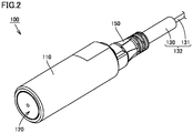
- Fig. 2 is a diagram showing an external appearance of proximity sensor 100.
- proximity sensor 100 includes an approximately cylindrical enclosure 110 made of metal, a sensing unit assembly 120 attached to a tip end portion of approximately cylindrical enclosure 110, a clamp 150 made of resin and attached to a base end portion of enclosure 110, and a cable 132 fixed to this clamp 150 through a joint interposing member (not shown).
- An electronic circuit is implemented in enclosure 110.
- cable 132 may be structured such that a plurality of cables 132 are coupled via a connector 160, as shown in Fig. 1 (connector 160 is not needed in the case of a single cable 132).
- Sensing unit assembly 120 has a structure in which a core (not shown) and a sensing coil (not shown) are contained in a coil case made of resin (not shown).
- Cable 132 includes a shielding material (not shown) and a sheath 130 that cover a core 131.
- Sheath 130 is made of a resin material such as fluororesin.
- Cable 132 is fixed to clamp 150 through a joint interposing member made of resin. The joint interposing member may be welded to sheath 130 of cable 132 for the purpose of sealing.
- Core 131 of cable 132 is electrically connected to the electronic circuit (now shown) in enclosure 110.
- the coil case of sensing unit assembly 120, sheath 130 of cable 132, and clamp 150 are made of resin and exposed at the outer surface of proximity sensor 100.
- oil resistance of these members becomes an issue.
- the cable may be fixed to the enclosure of the electronic device through an O ring or rubber bush, instead of clamp 150 and the joint interposing member described above.
- the O ring or rubber bush is exposed at the outer surface of the electronic device.
- oil resistance of the O ring or rubber bush becomes an issue.
- the tip of a measurement cord 16A which is one of two measurement cords 16A and 16B extending from insulation resistance meter 17, is immersed in a water-soluble cutting oil of Type A1, and the tip of the other measurement cord 16B is connected to the core of cable 132.
- the insulation resistance of proximity sensor 100 is measured through water-soluble cutting oil 15.
- Controller 18 detects an internal temperature of constant temperature oven 11 by a temperature sensor 19, and performs feedback control of an output from a heater (not shown) contained in constant temperature oven 11 such that the interior of constant temperature oven 11 is equal to a user-set test temperature. Controller 18 also determines that a failure has occurred in proximity sensor 100 when a measurement value of the insulation resistance becomes equal to or less than a reference value (for example, 50 M ⁇ ).
- a reference value for example, 50 M ⁇
- the insulation resistance of electronic device 100 to be tested is measured while electronic device 100 is simultaneously immersed in cutting oil 15 in constant temperature oven 11 in the above, the insulation resistance may be measured by taking electronic device 100 out of constant temperature oven 11 at regular time intervals. In this case, if there is no abnormality in the insulation resistance of the electronic device, electronic device 100 is put back in constant temperature oven 11 to continue the accelerated test.
- a cutting oil is diluted for use in the actual use environment, a stock solution of a cutting oil is used and an electronic device to be measured is immersed in this stock solution of the cutting oil in an accelerated test.
- the reason for using a stock solution is because a cutting oil that has intermittently splashed on an electronic device may be potentially dried and condensed on the surface of the electronic device in the actual use environment.
- a water-soluble cutting oil termed Type A1 in the JIS standard K2241 is used for the accelerated test.
- Type A1 refers to those "which are composed of a water-insoluble component such as mineral oil or fatty oil and a surfactant, and which exhibit a milky-white appearance when diluted with water.” It is noted that there are additional Type A2 and Type A3 water-soluble cutting oils.
- Type A2 refers to those "which are composed of a water-soluble component alone such as a surfactant, or composed of a water-soluble component and a water-insoluble component such as mineral oil or fatty oil, and which exhibit a translucent to transparent appearance when diluted with water.”
- Type A3 refers to those "which are composed of a water-soluble component, and which exhibit a transparent appearance when diluted with water.”
- cutting oils are classified into Type N1 to Type N4 which are four types of water-insoluble cutting oils, and Type A1 to Type A3 which are three types of water-soluble cutting oils.
- a cutting oil that causes quick progress of degradation of a resin member is selected for use in an accelerated test.
- a cutting oil that facilitates swelling, contraction and decomposition of a resin member is selected. The degree of swelling and contraction is evaluated by a rate of weight change and/or a rate of dimensional change.
- the water-insoluble cutting oils (Types N1 to N4) are excluded because they do not cause decomposition.
- the cutting oil of Type A3 is excluded because it does not contain a mineral oil which is a major contributing factor to swelling and contraction.
- Type A1 has a higher content of mineral oil and thus causes a higher degree of swelling and contraction. It is thus desirable to use the cutting oil of Type A1 as a cutting oil for an accelerated test.
- a ratio of components in the cutting oil may be adjusted so as to maximize the effect on the resin member.
- a test temperature for an accelerated test is set to a temperature higher than the use temperature. If a use temperature of an electronic device in the actual use environment is higher than room temperature (for example, in the vicinity of 40°C), an accelerated test temperature is again set to a temperature higher than the actual use temperature.
- the actual accelerated test temperature has a limiting temperature depending on the resin material exposed at the outer surface of an electronic device to be tested. For example, when a particular resin material is rapidly degraded at a high temperature (for example, when the temperature of a resin material having an ester group exceeds the glass transition point), there will be a significant difference from the actual use environment. When such a material is used, therefore, a low accelerated test temperature needs to be set. Specific examples will be cited and described below.
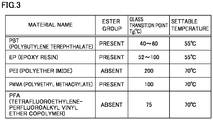
- Fig. 3 is a diagram showing a relationship between resin materials and settable test temperatures in table form.
- the test temperature is set to a lower temperature than when the resin material having an ester group is not provided. This is because an ester group undergoes hydrolysis in a water-soluble cutting oil of Type A1.
- PBT polybutylene terephthalate
- EP epoxy resin
- PMMA polymethyl methacrylate
- the test temperature is set based on a resin material having the lowest glass transition temperature among those materials.
- the test temperature is set to 55°C, which is a value substantially equivalent to the glass transition temperatures of these materials.
- the test temperature is set to 70°C in consideration of the glass transition temperature of PMMA (100°C).
- Fig. 4 is a flowchart showing the procedure of an accelerated test. Referring to Figs. 1 and 4 , the procedure of an accelerated test of oil resistance of an electronic device will be described below.
- step S I 10 electronic device 100 to be tested is immersed in cutting oil 15 (step S I 10).
- Type A1 of the JIS standard K2241 is employed as cutting oil 15.
- the temperature of constant temperature oven 11 (test temperature) is set depending on the type of a resin material provided on the outer surface of electronic device 100 (step S120).
- Controller 18 controls an output from the contained heater such that the internal temperature of constant temperature oven 11 becomes equal to the set test temperature, based on a detection value from temperature sensor 19.
- step S130 heating of electronic device 100 by constant temperature oven 11 is started by placing container 13 with cover 14 containing cutting oil 15 in constant temperature oven 11 together with electronic device 100 (step S130). Further, in the case of the apparatus configuration of Fig. 1 , the insulation resistance of electronic device 100 is measured while an accelerated test of oil resistance of electronic device 100 is conducted in an atmosphere of the test temperature (step S140). In contrast to this, the insulation resistance of electronic device 100 may be measured by taking electronic device 100 out of constant temperature oven 11 at regular time intervals.
- the insulation resistance is equal to or less than the reference value (for example, 50 M ⁇ ) as a result of the insulation resistance measurement described above (YES in step S150), it is determined that a failure or degradation has occurred in electronic device 100.
- the reference value for example, 50 M ⁇
- whether or not electronic device 100 operates normally can be determined based on the following criteria.
- the electronic device is a sensor, for example, whether or not the electronic device operates normally is determined based on whether or not a detection value varies.
- the electronic device is a switch, whether or not the electronic device operates normally is determined based on whether or not a contact operates properly in response to an input.
- the electronic device is a communication device such as an RFID (Radio Frequency Identifier)
- whether or not the electronic device operates normally is determined based on whether or not the communication device is communicating properly.
- the electronic device includes an IO (Input/Output) terminal, whether or not the IO terminal operates normally is determined based on whether or not an internal circuit functions normally. In this manner, the degradation of electronic device 100 can also be determined by measuring the electrical characteristics of electronic device 100 other than the insulation resistance.
- a degraded portion identified (step S160). Specifically, it is determined which portion has been degraded by measurement of insulation resistances of a plurality of portions.
- Figs. 5 to 8 are diagrams illustrating methods of measuring insulation resistances of enclosure 110, cable 132 between enclosure 110 and connector 160, connector 160, and cable 132 between connector 160 and insulation resistance meter 17, respectively.
- electronic device 100 includes enclosure (sensor body) 110 and cable 132 fixed to enclosure 110, where cable 132 has two parts which are connected via connector 160.
- only enclosure (sensor body) 110 when measuring the insulation resistance of only enclosure (sensor body) 110, only enclosure (sensor body) 110 is immersed in water 21 contained in a container 20. In this state, the tip of measurement cord 16A of insulation resistance meter 17 is immersed in the water, and the tip of measurement cord 16B is connected to the core of cable 132. The insulation resistance of only enclosure (sensor body) 110 can thereby be measured through the water. It is noted that a conductive liquid may be used instead of the water in the insulation resistance measurement described above.
- the enclosure of the electronic device When the cable is not directly connected to the enclosure of the electronic device (that is, when the cable is not included in the electronic device), the enclosure of the electronic device is provided with a connector to which the cable can be connected.
- the enclosure and measurement cord 16B By attaching a connector pairing with this connector provided on the enclosure to the tip of measurement cord 16B extending from insulation resistance meter 17, the enclosure and measurement cord 16B can be electrically connected to each other to measure the insulation resistance of only the enclosure.
- the enclosure and measurement cord 16B may be electrically connected to each other through a cable attached at one end to a connector pairing with the connector provided on the enclosure.
- Fig. 6 when measuring the insulation resistance of cable 132 between enclosure 110 and connector 160, the appropriate portion is immersed in the water. In this state, the tip of measurement cord 16A of insulation resistance meter 17 is immersed in the water, and the tip of measurement cord 16B is connected to the core of cable 132. It is noted that when the cable is not directly connected to the enclosure of the electronic device (that is, when the cable is not included in the electronic device), the measurement step of Fig. 6 is skipped.
- the tip of measurement cord 16A of insulation resistance meter 17 is brought into contact with connector 160 while being immersed in the water.
- the tip of measurement cord 16B is connected to the core of cable 132. It is noted that when the electronic device is not provided with connector 160, the measurement step of Fig. 7 is skipped.
- Fig. 8 when measuring the insulation resistance of cable 132 between connector 160 and insulation resistance meter 17, the appropriate portion is immersed in the water. In this state, the tip of measurement cord 16A of insulation resistance meter 17 is immersed in the water, and the tip of measurement cord 16B is connected to the core of cable 132. It is noted that when the cable is not directly connected to the enclosure of the electronic device (that is, when the cable is not included in the electronic device), the measurement step of Fig. 8 is skipped.
- the life of the oil resistance of electronic device 100 in the actual use environment is estimated based on a total value of immersion time of electronic device 100 in cutting oil 15 until that point in time (step S170).
- an estimated value of the life of electronic device 100 can be calculated by multiplying the total value of immersion time by a predetermined acceleration factor. The procedure of determining the acceleration factor is described next.
- Fig. 9 is a flowchart showing the procedure of determining the acceleration factor.
- a plurality of electronic devices (first to third electronic devices hereinafter) of the same design are used in determining the acceleration factor.
- a degradation time for example, an amount of time until the insulation resistance becomes equal to or less than the reference value
- a degraded portion of the first electronic device are detected (step S210).
- the methods described with reference to Figs. 5 to 8 are used to detect the degraded portion.
- step S220 a degradation time and a degraded portion of the second electronic device are detected by an accelerated test (atmosphere of higher temperature than in the actual use environment, immersion in a cutting oil of Type A1).
- an accelerated test atmosphere of higher temperature than in the actual use environment, immersion in a cutting oil of Type A1
- step S230 it is determined whether or not the degraded portion is the same between in the actual use environment and in the accelerated test (step S230).
- the test temperature for the accelerated test is changed to a lower temperature (step S240), and the accelerated test (step S220 described above) is conducted again using the third electronic device.
- an acceleration factor (L1/L2) is determined from an elapsed time (LI) before the degradation of electronic device 100 in the actual use environment and a total immersion time (L2) in the cutting oil in the accelerated test (step S250).
- LI elapsed time
- L2 total immersion time
- the cutting oil of Type A1 of the JIS standard K2241 is used in the accelerated test, thus allowing the accelerated test to be conducted efficiently. Further, the test temperature for the accelerated test is set depending on the resin material used for the electronic device to be tested, so that the same phenomenon as that in the actual use environment can be reproduced in the accelerated test, thus allowing the acceleration factor to be set appropriately.
Landscapes
- Chemical & Material Sciences (AREA)
- Life Sciences & Earth Sciences (AREA)
- Physics & Mathematics (AREA)
- General Physics & Mathematics (AREA)
- Health & Medical Sciences (AREA)
- Immunology (AREA)
- Biochemistry (AREA)
- General Health & Medical Sciences (AREA)
- Analytical Chemistry (AREA)
- Pathology (AREA)
- Environmental & Geological Engineering (AREA)
- Engineering & Computer Science (AREA)
- Chemical Kinetics & Catalysis (AREA)
- Electrochemistry (AREA)
- Ecology (AREA)
- Biodiversity & Conservation Biology (AREA)
- Environmental Sciences (AREA)
- Food Science & Technology (AREA)
- Medicinal Chemistry (AREA)
- Spectroscopy & Molecular Physics (AREA)
- Testing Resistance To Weather, Investigating Materials By Mechanical Methods (AREA)
- Testing Of Short-Circuits, Discontinuities, Leakage, Or Incorrect Line Connections (AREA)
- Investigating Or Analyzing Materials By The Use Of Electric Means (AREA)
Claims (5)
- Procédé de test de résistance à l'huile destiné à un dispositif électronique (100), avec au moins un type de résine prévu sur au moins une partie d'une surface externe du dispositif électronique (100), le procédé de test de résistance à l'huile comprenant :la définition d'une température de test ;l'immersion du dispositif électronique (100) dans une huile de coupe soluble dans l'eau (15) dans une atmosphère de la température de test, l'huile de coupe (15) contenant une huile minérale et un tensioactif et présentant une apparence blanc laiteux lorsqu'elle est diluée avec l'eau ; etla détermination, sur la base d'une caractéristique électrique du dispositif électronique (100), du fait que le dispositif électronique (100) ait été dégradé ou non par l'huile de coupe (15), dans lequel la détermination du fait que le dispositif électronique (100) ait été dégradé ou non comprend :la détermination du fait qu'une valeur de résistance d'isolation du dispositif électronique (100) soit devenue ou non égale ou inférieure à une valeur de référence, oula mesure d'une caractéristique électrique du dispositif électronique (100) dans un état sous tension ;caractérisé en ce que le procédé comprend en outre :l'estimation, sur la base d'une durée totale d'immersion du dispositif électronique (100) dans l'huile de coupe (15) jusqu'à ce que la dégradation du dispositif électronique (100) soit détectée, d'une durée de vie du dispositif électronique (100) par rapport à la résistance à l'huile,dans lequel une valeur estimée de la durée de vie est calculée en multipliant la durée totale d'immersion par un facteur d'accélération prédéterminé, etdans lequel le facteur d'accélération est calculé, à l'aide d'un premier et d'un second dispositifs électroniques (100) de conception identique, par un rapport entre une durée jusqu'à ce que le premier dispositif électronique soit dégradé dans un environnement d'utilisation réel et une durée totale d'immersion du second dispositif électronique dans l'huile de coupe (15) jusqu'à ce que le second dispositif électronique soit dégradé au niveau d'une partie identique à une partie dégradée du premier dispositif électronique dans l'atmosphère de la température de test.
- Procédé de test de résistance à l'huile selon la revendication 1, dans lequelle au moins un type de résine comprend un ou plusieurs type(s) de résines qui présentent chacun un groupe ester, etla température de test est définie sur la base d'une résine qui présente la température de transition vitreuse la plus basse parmi le ou les type(s) de résines qui présentent chacun un groupe ester.
- Procédé de test de résistance à l'huile selon la revendication 1 ou 2, comprenant en outre, lorsqu'il est détecté que le dispositif électronique (100) a été dégradé, la détermination de l'une d'une pluralité de parties divisées du dispositif électronique (100) qui a été dégradée, en mesurant la résistance d'isolation de chaque partie de la pluralité de parties.
- Appareil de test de résistance à l'huile (10) destiné à un dispositif électronique (100), comprenant :un four à température constante (11) ;un contenant (13) prévu dans le four à température constante (11), afin de contenir une huile de coupe soluble dans l'eau (15) dans laquelle le dispositif électronique (100) doit être immergé ;un dispositif de mesure de résistance d'isolation (17) destiné à mesurer la résistance d'isolation du dispositif électronique (100) par le biais de l'huile de coupe soluble dans l'eau (15) ; etun contrôleur (18) destiné à contrôler une température du four à température constante (11) afin qu'elle reste constante,dans lequel le contrôleur (18) est configuré pour déterminer si la résistance d'isolation du dispositif électronique (100) est devenue égale ou inférieure à une valeur de référence,dans lequel au moins un type de résine est prévu sur au moins une partie d'une surface externe du dispositif électronique (100),dans lequel l'huile de coupe soluble dans l'eau (15) contient une huile minérale et un tensioactif et présente une apparence blanc laiteux lorsqu'elle est diluée dans l'eau,caractérisé en ce quele contrôleur (18) est configuré pour estimer une durée de vie du dispositif électronique (100) par rapport à la résistance à l'huile, sur la base d'une durée totale d'immersion du dispositif électronique (100) dans l'huile de coupe soluble dans l'eau (15) jusqu'à ce que la résistance d'isolation du dispositif électronique (100) devienne égale ou inférieure à la valeur de référence,dans lequel le contrôleur (18) est configuré pour calculer une valeur estimée de la durée de vie en multipliant la durée totale d'immersion par un facteur d'accélération prédéterminé,dans lequel le facteur d'accélération est égal à une valeur d'un rapport entre une durée jusqu'à ce qu'il soit déterminé qu'un premier dispositif électronique (100) ait été dégradé dans un environnement d'utilisation réel sur la base d'une résistance d'isolation du premier dispositif électronique qui devient égale ou inférieure à la valeur de référence et une durée totale d'immersion d'un second dispositif électronique (100) dans l'huile de coupe (15) jusqu'à ce qu'il soit déterminé que le second dispositif électronique ait été dégradé au niveau d'une partie identique à une partie dégradée du premier dispositif électronique dans une atmosphère de la température de test, etdans lequel le premier et le second dispositifs électroniques (100) sont des dispositifs électroniques de conception identique.
- Appareil de test de résistance à l'huile (10) destiné à un dispositif électronique (100) selon la revendication 4, dans lequelle au moins un type de résine comprend un ou plusieurs type(s) de résines qui présentent chacun un groupe ester, etle contrôleur (18) est configuré, pendant un test de résistance à l'huile du dispositif électronique (100), pour contrôler la température du four à température constante (11) afin qu'elle soit égale à une température de test déterminée sur la base d'une résine qui présente la température de transition vitreuse la plus basse parmi le ou les types de résines qui présentent chacun un groupe ester.
Applications Claiming Priority (1)
| Application Number | Priority Date | Filing Date | Title |
|---|---|---|---|
| JP2016071146A JP6786842B2 (ja) | 2016-03-31 | 2016-03-31 | 耐油性試験方法および耐油性試験装置 |
Publications (2)
| Publication Number | Publication Date |
|---|---|
| EP3225973A1 EP3225973A1 (fr) | 2017-10-04 |
| EP3225973B1 true EP3225973B1 (fr) | 2021-11-03 |
Family
ID=58360806
Family Applications (1)
| Application Number | Title | Priority Date | Filing Date |
|---|---|---|---|
| EP17155245.8A Not-in-force EP3225973B1 (fr) | 2016-03-31 | 2017-02-08 | Procédé de test de résistance à l'huile et appareil de test de résistance à l'huile |
Country Status (4)
| Country | Link |
|---|---|
| US (1) | US10330721B2 (fr) |
| EP (1) | EP3225973B1 (fr) |
| JP (1) | JP6786842B2 (fr) |
| CN (1) | CN107271491B (fr) |
Families Citing this family (5)
| Publication number | Priority date | Publication date | Assignee | Title |
|---|---|---|---|---|
| CN109774967B (zh) * | 2017-11-13 | 2021-10-15 | 中航通飞华南飞机工业有限公司 | 模拟发动机滑油温度与航电系统交联在线检测方法 |
| CN109269911A (zh) * | 2018-07-25 | 2019-01-25 | 安徽顺信线缆有限公司 | 一种防水电缆测试方法及其测试装置 |
| CN110927460A (zh) * | 2019-12-05 | 2020-03-27 | 芜湖航天特种电缆厂股份有限公司 | 绝缘电阻的测量方法 |
| CN112198109A (zh) * | 2020-09-22 | 2021-01-08 | 中国电力科学研究院有限公司 | 一种电流互感器用复合绝缘外套的耐油试验工装及耐油试验方法 |
| EP4538690A1 (fr) * | 2023-10-09 | 2025-04-16 | NKT HV Cables AB | Procédé de détermination de compatibilité entre un matériau d'isolation polymère et un matériau étranger |
Family Cites Families (10)
| Publication number | Priority date | Publication date | Assignee | Title |
|---|---|---|---|---|
| JPH082892Y2 (ja) | 1988-05-20 | 1996-01-29 | 株式会社キーエンス | 検出スイッチ |
| DE10230759A1 (de) * | 2002-07-09 | 2004-01-22 | Zf Friedrichshafen Ag | Verfahren und Einrichtung zur Maschinendiagnose und insbesondere zur Getriebediagnose |
| JP2008117691A (ja) * | 2006-11-07 | 2008-05-22 | Sumitomo Electric Ind Ltd | ノンハロゲン絶縁電線 |
| JP4784679B2 (ja) | 2009-05-27 | 2011-10-05 | オムロン株式会社 | 耐油性電子機器およびその製造方法 |
| CN102087188A (zh) | 2009-12-07 | 2011-06-08 | 屠国强 | 一种氟橡胶的测试分析方法 |
| JP5234440B2 (ja) * | 2010-02-17 | 2013-07-10 | 三菱電機株式会社 | 油入電気機器の寿命診断装置、油入電気機器の寿命診断方法、油入電気機器の劣化抑制装置、および油入電気機器の劣化抑制方法 |
| US8629688B2 (en) * | 2010-09-29 | 2014-01-14 | International Business Machines Corporation | Method for sulfur-based corrosion testing |
| JP6142582B2 (ja) * | 2013-03-08 | 2017-06-07 | オムロン株式会社 | ケーブル被覆材料、被覆ケーブルおよび電子機器 |
| JP6327933B2 (ja) * | 2013-06-28 | 2018-05-23 | 株式会社クレハ | ダウンホールツール用ゴム部材、及びダウンホールツール、並びに炭化水素資源の回収方法 |
| JP6359888B2 (ja) * | 2013-12-27 | 2018-07-18 | 株式会社クレハ | ダウンホールツール用の拡径可能な環状の分解性シール部材、及び坑井掘削用プラグ、並びに坑井掘削方法 |
-
2016
- 2016-03-31 JP JP2016071146A patent/JP6786842B2/ja not_active Expired - Fee Related
-
2017
- 2017-02-06 US US15/425,449 patent/US10330721B2/en active Active
- 2017-02-08 CN CN201710068566.1A patent/CN107271491B/zh not_active Expired - Fee Related
- 2017-02-08 EP EP17155245.8A patent/EP3225973B1/fr not_active Not-in-force
Also Published As
| Publication number | Publication date |
|---|---|
| CN107271491B (zh) | 2020-02-07 |
| JP2017181371A (ja) | 2017-10-05 |
| CN107271491A (zh) | 2017-10-20 |
| US10330721B2 (en) | 2019-06-25 |
| EP3225973A1 (fr) | 2017-10-04 |
| US20170285093A1 (en) | 2017-10-05 |
| JP6786842B2 (ja) | 2020-11-18 |
Similar Documents
| Publication | Publication Date | Title |
|---|---|---|
| EP3225973B1 (fr) | Procédé de test de résistance à l'huile et appareil de test de résistance à l'huile | |
| CN213902686U (zh) | 一种烘烤用无线温度探针 | |
| EP1742042B1 (fr) | Capteur de détection de l'état liquide | |
| CN113758597A (zh) | 温度探针和烤箱组件 | |
| CN102735888A (zh) | 探针结构与探针制造方法 | |
| US7637148B2 (en) | Liquid state detecting sensor | |
| JP2023107032A (ja) | 絶縁抵抗検出装置および故障検出方法 | |
| JP5030239B2 (ja) | ガスセンサの異常診断装置および異常診断方法 | |
| FI81681B (fi) | Foerfarande och anordning foer att oevervaka intraeffande av en haendelse. | |
| CN207456645U (zh) | 温度变送器和温度变送器组件 | |
| US8044811B2 (en) | Sensing device and method | |
| US20050207473A1 (en) | Thermistor probe assembly and method for positioning and moisture proofing thermistor probe assembly | |
| CN107843543B (zh) | 电能存储单元的至少部分导电外壳内腐蚀检测方法和设备 | |
| CN113567494A (zh) | 一种电力复合脂的老化程度测试方法及模型 | |
| JP2002277333A (ja) | 劣化判定方法及び劣化判定装置 | |
| JPS62215194A (ja) | 断熱板及びその検査方法 | |
| CN108469546B (zh) | 一种线材阻抗测试方法及系统 | |
| CN208520921U (zh) | 温升试验绕组阻值自动检测装置 | |
| CN115200733A (zh) | 一种带双热熔断体的热敏电阻传感器 | |
| CN115014562A (zh) | 一种带单热熔断体的热敏电阻传感器 | |
| CN208168948U (zh) | 一种电子式机油标尺 | |
| US10008094B2 (en) | Electric meter apparatus with light-blinking function | |
| US8232812B2 (en) | Corrosion testing method | |
| TWI412750B (zh) | Probe circuit | |
| JP2007281275A (ja) | モールド変圧器の劣化診断方法 |
Legal Events
| Date | Code | Title | Description |
|---|---|---|---|
| PUAI | Public reference made under article 153(3) epc to a published international application that has entered the european phase |
Free format text: ORIGINAL CODE: 0009012 |
|
| STAA | Information on the status of an ep patent application or granted ep patent |
Free format text: STATUS: REQUEST FOR EXAMINATION WAS MADE |
|
| 17P | Request for examination filed |
Effective date: 20170224 |
|
| AK | Designated contracting states |
Kind code of ref document: A1 Designated state(s): AL AT BE BG CH CY CZ DE DK EE ES FI FR GB GR HR HU IE IS IT LI LT LU LV MC MK MT NL NO PL PT RO RS SE SI SK SM TR |
|
| AX | Request for extension of the european patent |
Extension state: BA ME |
|
| STAA | Information on the status of an ep patent application or granted ep patent |
Free format text: STATUS: EXAMINATION IS IN PROGRESS |
|
| 17Q | First examination report despatched |
Effective date: 20210401 |
|
| GRAP | Despatch of communication of intention to grant a patent |
Free format text: ORIGINAL CODE: EPIDOSNIGR1 |
|
| STAA | Information on the status of an ep patent application or granted ep patent |
Free format text: STATUS: GRANT OF PATENT IS INTENDED |
|
| INTG | Intention to grant announced |
Effective date: 20210714 |
|
| GRAS | Grant fee paid |
Free format text: ORIGINAL CODE: EPIDOSNIGR3 |
|
| GRAA | (expected) grant |
Free format text: ORIGINAL CODE: 0009210 |
|
| STAA | Information on the status of an ep patent application or granted ep patent |
Free format text: STATUS: THE PATENT HAS BEEN GRANTED |
|
| AK | Designated contracting states |
Kind code of ref document: B1 Designated state(s): AL AT BE BG CH CY CZ DE DK EE ES FI FR GB GR HR HU IE IS IT LI LT LU LV MC MK MT NL NO PL PT RO RS SE SI SK SM TR |
|
| REG | Reference to a national code |
Ref country code: GB Ref legal event code: FG4D |
|
| REG | Reference to a national code |
Ref country code: AT Ref legal event code: REF Ref document number: 1444390 Country of ref document: AT Kind code of ref document: T Effective date: 20211115 Ref country code: CH Ref legal event code: EP |
|
| REG | Reference to a national code |
Ref country code: DE Ref legal event code: R096 Ref document number: 602017048568 Country of ref document: DE |
|
| REG | Reference to a national code |
Ref country code: IE Ref legal event code: FG4D |
|
| REG | Reference to a national code |
Ref country code: LT Ref legal event code: MG9D |
|
| REG | Reference to a national code |
Ref country code: NL Ref legal event code: MP Effective date: 20211103 |
|
| REG | Reference to a national code |
Ref country code: AT Ref legal event code: MK05 Ref document number: 1444390 Country of ref document: AT Kind code of ref document: T Effective date: 20211103 |
|
| PG25 | Lapsed in a contracting state [announced via postgrant information from national office to epo] |
Ref country code: RS Free format text: LAPSE BECAUSE OF FAILURE TO SUBMIT A TRANSLATION OF THE DESCRIPTION OR TO PAY THE FEE WITHIN THE PRESCRIBED TIME-LIMIT Effective date: 20211103 Ref country code: LT Free format text: LAPSE BECAUSE OF FAILURE TO SUBMIT A TRANSLATION OF THE DESCRIPTION OR TO PAY THE FEE WITHIN THE PRESCRIBED TIME-LIMIT Effective date: 20211103 Ref country code: FI Free format text: LAPSE BECAUSE OF FAILURE TO SUBMIT A TRANSLATION OF THE DESCRIPTION OR TO PAY THE FEE WITHIN THE PRESCRIBED TIME-LIMIT Effective date: 20211103 Ref country code: BG Free format text: LAPSE BECAUSE OF FAILURE TO SUBMIT A TRANSLATION OF THE DESCRIPTION OR TO PAY THE FEE WITHIN THE PRESCRIBED TIME-LIMIT Effective date: 20220203 Ref country code: AT Free format text: LAPSE BECAUSE OF FAILURE TO SUBMIT A TRANSLATION OF THE DESCRIPTION OR TO PAY THE FEE WITHIN THE PRESCRIBED TIME-LIMIT Effective date: 20211103 |
|
| PG25 | Lapsed in a contracting state [announced via postgrant information from national office to epo] |
Ref country code: IS Free format text: LAPSE BECAUSE OF FAILURE TO SUBMIT A TRANSLATION OF THE DESCRIPTION OR TO PAY THE FEE WITHIN THE PRESCRIBED TIME-LIMIT Effective date: 20220303 Ref country code: SE Free format text: LAPSE BECAUSE OF FAILURE TO SUBMIT A TRANSLATION OF THE DESCRIPTION OR TO PAY THE FEE WITHIN THE PRESCRIBED TIME-LIMIT Effective date: 20211103 Ref country code: PT Free format text: LAPSE BECAUSE OF FAILURE TO SUBMIT A TRANSLATION OF THE DESCRIPTION OR TO PAY THE FEE WITHIN THE PRESCRIBED TIME-LIMIT Effective date: 20220303 Ref country code: PL Free format text: LAPSE BECAUSE OF FAILURE TO SUBMIT A TRANSLATION OF THE DESCRIPTION OR TO PAY THE FEE WITHIN THE PRESCRIBED TIME-LIMIT Effective date: 20211103 Ref country code: NO Free format text: LAPSE BECAUSE OF FAILURE TO SUBMIT A TRANSLATION OF THE DESCRIPTION OR TO PAY THE FEE WITHIN THE PRESCRIBED TIME-LIMIT Effective date: 20220203 Ref country code: NL Free format text: LAPSE BECAUSE OF FAILURE TO SUBMIT A TRANSLATION OF THE DESCRIPTION OR TO PAY THE FEE WITHIN THE PRESCRIBED TIME-LIMIT Effective date: 20211103 Ref country code: LV Free format text: LAPSE BECAUSE OF FAILURE TO SUBMIT A TRANSLATION OF THE DESCRIPTION OR TO PAY THE FEE WITHIN THE PRESCRIBED TIME-LIMIT Effective date: 20211103 Ref country code: HR Free format text: LAPSE BECAUSE OF FAILURE TO SUBMIT A TRANSLATION OF THE DESCRIPTION OR TO PAY THE FEE WITHIN THE PRESCRIBED TIME-LIMIT Effective date: 20211103 Ref country code: GR Free format text: LAPSE BECAUSE OF FAILURE TO SUBMIT A TRANSLATION OF THE DESCRIPTION OR TO PAY THE FEE WITHIN THE PRESCRIBED TIME-LIMIT Effective date: 20220204 Ref country code: ES Free format text: LAPSE BECAUSE OF FAILURE TO SUBMIT A TRANSLATION OF THE DESCRIPTION OR TO PAY THE FEE WITHIN THE PRESCRIBED TIME-LIMIT Effective date: 20211103 |
|
| PG25 | Lapsed in a contracting state [announced via postgrant information from national office to epo] |
Ref country code: SM Free format text: LAPSE BECAUSE OF FAILURE TO SUBMIT A TRANSLATION OF THE DESCRIPTION OR TO PAY THE FEE WITHIN THE PRESCRIBED TIME-LIMIT Effective date: 20211103 Ref country code: SK Free format text: LAPSE BECAUSE OF FAILURE TO SUBMIT A TRANSLATION OF THE DESCRIPTION OR TO PAY THE FEE WITHIN THE PRESCRIBED TIME-LIMIT Effective date: 20211103 Ref country code: RO Free format text: LAPSE BECAUSE OF FAILURE TO SUBMIT A TRANSLATION OF THE DESCRIPTION OR TO PAY THE FEE WITHIN THE PRESCRIBED TIME-LIMIT Effective date: 20211103 Ref country code: EE Free format text: LAPSE BECAUSE OF FAILURE TO SUBMIT A TRANSLATION OF THE DESCRIPTION OR TO PAY THE FEE WITHIN THE PRESCRIBED TIME-LIMIT Effective date: 20211103 Ref country code: DK Free format text: LAPSE BECAUSE OF FAILURE TO SUBMIT A TRANSLATION OF THE DESCRIPTION OR TO PAY THE FEE WITHIN THE PRESCRIBED TIME-LIMIT Effective date: 20211103 Ref country code: CZ Free format text: LAPSE BECAUSE OF FAILURE TO SUBMIT A TRANSLATION OF THE DESCRIPTION OR TO PAY THE FEE WITHIN THE PRESCRIBED TIME-LIMIT Effective date: 20211103 |
|
| REG | Reference to a national code |
Ref country code: DE Ref legal event code: R097 Ref document number: 602017048568 Country of ref document: DE |
|
| PLBE | No opposition filed within time limit |
Free format text: ORIGINAL CODE: 0009261 |
|
| STAA | Information on the status of an ep patent application or granted ep patent |
Free format text: STATUS: NO OPPOSITION FILED WITHIN TIME LIMIT |
|
| PG25 | Lapsed in a contracting state [announced via postgrant information from national office to epo] |
Ref country code: MC Free format text: LAPSE BECAUSE OF FAILURE TO SUBMIT A TRANSLATION OF THE DESCRIPTION OR TO PAY THE FEE WITHIN THE PRESCRIBED TIME-LIMIT Effective date: 20211103 |
|
| 26N | No opposition filed |
Effective date: 20220804 |
|
| REG | Reference to a national code |
Ref country code: CH Ref legal event code: PL |
|
| REG | Reference to a national code |
Ref country code: BE Ref legal event code: MM Effective date: 20220228 |
|
| GBPC | Gb: european patent ceased through non-payment of renewal fee |
Effective date: 20220208 |
|
| PG25 | Lapsed in a contracting state [announced via postgrant information from national office to epo] |
Ref country code: LU Free format text: LAPSE BECAUSE OF NON-PAYMENT OF DUE FEES Effective date: 20220208 Ref country code: AL Free format text: LAPSE BECAUSE OF FAILURE TO SUBMIT A TRANSLATION OF THE DESCRIPTION OR TO PAY THE FEE WITHIN THE PRESCRIBED TIME-LIMIT Effective date: 20211103 |
|
| PG25 | Lapsed in a contracting state [announced via postgrant information from national office to epo] |
Ref country code: SI Free format text: LAPSE BECAUSE OF FAILURE TO SUBMIT A TRANSLATION OF THE DESCRIPTION OR TO PAY THE FEE WITHIN THE PRESCRIBED TIME-LIMIT Effective date: 20211103 |
|
| PG25 | Lapsed in a contracting state [announced via postgrant information from national office to epo] |
Ref country code: FR Free format text: LAPSE BECAUSE OF NON-PAYMENT OF DUE FEES Effective date: 20220228 |
|
| PG25 | Lapsed in a contracting state [announced via postgrant information from national office to epo] |
Ref country code: LI Free format text: LAPSE BECAUSE OF NON-PAYMENT OF DUE FEES Effective date: 20220228 Ref country code: IE Free format text: LAPSE BECAUSE OF NON-PAYMENT OF DUE FEES Effective date: 20220208 Ref country code: GB Free format text: LAPSE BECAUSE OF NON-PAYMENT OF DUE FEES Effective date: 20220208 Ref country code: CH Free format text: LAPSE BECAUSE OF NON-PAYMENT OF DUE FEES Effective date: 20220228 |
|
| PG25 | Lapsed in a contracting state [announced via postgrant information from national office to epo] |
Ref country code: BE Free format text: LAPSE BECAUSE OF NON-PAYMENT OF DUE FEES Effective date: 20220228 |
|
| PG25 | Lapsed in a contracting state [announced via postgrant information from national office to epo] |
Ref country code: IT Free format text: LAPSE BECAUSE OF FAILURE TO SUBMIT A TRANSLATION OF THE DESCRIPTION OR TO PAY THE FEE WITHIN THE PRESCRIBED TIME-LIMIT Effective date: 20211103 |
|
| PGFP | Annual fee paid to national office [announced via postgrant information from national office to epo] |
Ref country code: DE Payment date: 20221229 Year of fee payment: 7 |
|
| PG25 | Lapsed in a contracting state [announced via postgrant information from national office to epo] |
Ref country code: HU Free format text: LAPSE BECAUSE OF FAILURE TO SUBMIT A TRANSLATION OF THE DESCRIPTION OR TO PAY THE FEE WITHIN THE PRESCRIBED TIME-LIMIT; INVALID AB INITIO Effective date: 20170208 |
|
| PG25 | Lapsed in a contracting state [announced via postgrant information from national office to epo] |
Ref country code: MK Free format text: LAPSE BECAUSE OF FAILURE TO SUBMIT A TRANSLATION OF THE DESCRIPTION OR TO PAY THE FEE WITHIN THE PRESCRIBED TIME-LIMIT Effective date: 20211103 Ref country code: CY Free format text: LAPSE BECAUSE OF FAILURE TO SUBMIT A TRANSLATION OF THE DESCRIPTION OR TO PAY THE FEE WITHIN THE PRESCRIBED TIME-LIMIT Effective date: 20211103 |
|
| REG | Reference to a national code |
Ref country code: DE Ref legal event code: R119 Ref document number: 602017048568 Country of ref document: DE |
|
| PG25 | Lapsed in a contracting state [announced via postgrant information from national office to epo] |
Ref country code: MT Free format text: LAPSE BECAUSE OF FAILURE TO SUBMIT A TRANSLATION OF THE DESCRIPTION OR TO PAY THE FEE WITHIN THE PRESCRIBED TIME-LIMIT Effective date: 20211103 |
|
| PG25 | Lapsed in a contracting state [announced via postgrant information from national office to epo] |
Ref country code: DE Free format text: LAPSE BECAUSE OF NON-PAYMENT OF DUE FEES Effective date: 20240903 |
|
| PG25 | Lapsed in a contracting state [announced via postgrant information from national office to epo] |
Ref country code: DE Free format text: LAPSE BECAUSE OF NON-PAYMENT OF DUE FEES Effective date: 20240903 |
|
| PG25 | Lapsed in a contracting state [announced via postgrant information from national office to epo] |
Ref country code: TR Free format text: LAPSE BECAUSE OF FAILURE TO SUBMIT A TRANSLATION OF THE DESCRIPTION OR TO PAY THE FEE WITHIN THE PRESCRIBED TIME-LIMIT Effective date: 20211103 |