EP3226077A2 - Entwicklerhaltige einheit, entwicklungsverarbeitungseinheit, entwicklungseinheit und bilderzeugungsvorrichtung - Google Patents
Entwicklerhaltige einheit, entwicklungsverarbeitungseinheit, entwicklungseinheit und bilderzeugungsvorrichtung Download PDFInfo
- Publication number
- EP3226077A2 EP3226077A2 EP17161478.7A EP17161478A EP3226077A2 EP 3226077 A2 EP3226077 A2 EP 3226077A2 EP 17161478 A EP17161478 A EP 17161478A EP 3226077 A2 EP3226077 A2 EP 3226077A2
- Authority
- EP
- European Patent Office
- Prior art keywords
- protrusion
- unit
- developer
- fixing
- regulating member
- Prior art date
- Legal status (The legal status is an assumption and is not a legal conclusion. Google has not performed a legal analysis and makes no representation as to the accuracy of the status listed.)
- Withdrawn
Links
- 238000011161 development Methods 0.000 title claims abstract description 228
- 238000012545 processing Methods 0.000 title claims description 28
- 230000004044 response Effects 0.000 claims abstract description 34
- 238000003780 insertion Methods 0.000 claims description 502
- 230000037431 insertion Effects 0.000 claims description 502
- 230000001105 regulatory effect Effects 0.000 claims description 392
- 238000012546 transfer Methods 0.000 claims description 87
- 238000000034 method Methods 0.000 description 69
- 238000005516 engineering process Methods 0.000 description 54
- 230000008569 process Effects 0.000 description 41
- 230000006870 function Effects 0.000 description 28
- 230000001276 controlling effect Effects 0.000 description 26
- 230000000694 effects Effects 0.000 description 22
- 238000004140 cleaning Methods 0.000 description 17
- 229910052751 metal Inorganic materials 0.000 description 15
- 239000002184 metal Substances 0.000 description 15
- 238000010438 heat treatment Methods 0.000 description 13
- 230000004048 modification Effects 0.000 description 11
- 238000012986 modification Methods 0.000 description 11
- 238000010586 diagram Methods 0.000 description 8
- 230000003245 working effect Effects 0.000 description 8
- 238000003756 stirring Methods 0.000 description 7
- 230000007246 mechanism Effects 0.000 description 6
- 239000003086 colorant Substances 0.000 description 5
- 230000007423 decrease Effects 0.000 description 5
- 230000002093 peripheral effect Effects 0.000 description 5
- 239000000463 material Substances 0.000 description 4
- 239000007769 metal material Substances 0.000 description 4
- 229910052782 aluminium Inorganic materials 0.000 description 3
- XAGFODPZIPBFFR-UHFFFAOYSA-N aluminium Chemical compound [Al] XAGFODPZIPBFFR-UHFFFAOYSA-N 0.000 description 3
- 230000008859 change Effects 0.000 description 3
- 239000011248 coating agent Substances 0.000 description 3
- 238000000576 coating method Methods 0.000 description 3
- 239000011347 resin Substances 0.000 description 3
- 229920005989 resin Polymers 0.000 description 3
- 230000002123 temporal effect Effects 0.000 description 3
- 229920006311 Urethane elastomer Polymers 0.000 description 2
- 230000004075 alteration Effects 0.000 description 2
- 230000000903 blocking effect Effects 0.000 description 2
- 150000001875 compounds Chemical class 0.000 description 2
- 230000001747 exhibiting effect Effects 0.000 description 2
- 229920000642 polymer Polymers 0.000 description 2
- 229920001343 polytetrafluoroethylene Polymers 0.000 description 2
- 239000004810 polytetrafluoroethylene Substances 0.000 description 2
- 239000004642 Polyimide Substances 0.000 description 1
- 230000015572 biosynthetic process Effects 0.000 description 1
- 229920001577 copolymer Polymers 0.000 description 1
- 230000004069 differentiation Effects 0.000 description 1
- 239000013013 elastic material Substances 0.000 description 1
- 229920001971 elastomer Polymers 0.000 description 1
- 229920005558 epichlorohydrin rubber Polymers 0.000 description 1
- 229910052736 halogen Inorganic materials 0.000 description 1
- 150000002367 halogens Chemical class 0.000 description 1
- 230000006872 improvement Effects 0.000 description 1
- 108091008695 photoreceptors Proteins 0.000 description 1
- 229920001721 polyimide Polymers 0.000 description 1
- 239000002861 polymer material Substances 0.000 description 1
- 229920001296 polysiloxane Polymers 0.000 description 1
- -1 polytetrafluoroethylene Polymers 0.000 description 1
- 230000009467 reduction Effects 0.000 description 1
- 229910001220 stainless steel Inorganic materials 0.000 description 1
- 239000010935 stainless steel Substances 0.000 description 1
- BFKJFAAPBSQJPD-UHFFFAOYSA-N tetrafluoroethene Chemical group FC(F)=C(F)F BFKJFAAPBSQJPD-UHFFFAOYSA-N 0.000 description 1
- 238000011144 upstream manufacturing Methods 0.000 description 1
Images




Classifications
-
- G—PHYSICS
- G03—PHOTOGRAPHY; CINEMATOGRAPHY; ANALOGOUS TECHNIQUES USING WAVES OTHER THAN OPTICAL WAVES; ELECTROGRAPHY; HOLOGRAPHY
- G03G—ELECTROGRAPHY; ELECTROPHOTOGRAPHY; MAGNETOGRAPHY
- G03G21/00—Arrangements not provided for by groups G03G13/00 - G03G19/00, e.g. cleaning, elimination of residual charge
- G03G21/16—Mechanical means for facilitating the maintenance of the apparatus, e.g. modular arrangements
- G03G21/1642—Mechanical means for facilitating the maintenance of the apparatus, e.g. modular arrangements for connecting the different parts of the apparatus
- G03G21/1647—Mechanical connection means
-
- G—PHYSICS
- G03—PHOTOGRAPHY; CINEMATOGRAPHY; ANALOGOUS TECHNIQUES USING WAVES OTHER THAN OPTICAL WAVES; ELECTROGRAPHY; HOLOGRAPHY
- G03G—ELECTROGRAPHY; ELECTROPHOTOGRAPHY; MAGNETOGRAPHY
- G03G15/00—Apparatus for electrographic processes using a charge pattern
- G03G15/06—Apparatus for electrographic processes using a charge pattern for developing
- G03G15/08—Apparatus for electrographic processes using a charge pattern for developing using a solid developer, e.g. powder developer
- G03G15/0896—Arrangements or disposition of the complete developer unit or parts thereof not provided for by groups G03G15/08 - G03G15/0894
-
- G—PHYSICS
- G03—PHOTOGRAPHY; CINEMATOGRAPHY; ANALOGOUS TECHNIQUES USING WAVES OTHER THAN OPTICAL WAVES; ELECTROGRAPHY; HOLOGRAPHY
- G03G—ELECTROGRAPHY; ELECTROPHOTOGRAPHY; MAGNETOGRAPHY
- G03G21/00—Arrangements not provided for by groups G03G13/00 - G03G19/00, e.g. cleaning, elimination of residual charge
- G03G21/16—Mechanical means for facilitating the maintenance of the apparatus, e.g. modular arrangements
- G03G21/18—Mechanical means for facilitating the maintenance of the apparatus, e.g. modular arrangements using a processing cartridge, whereby the process cartridge comprises at least two image processing means in a single unit
- G03G21/1803—Arrangements or disposition of the complete process cartridge or parts thereof
- G03G21/1817—Arrangements or disposition of the complete process cartridge or parts thereof having a submodular arrangement
- G03G21/1821—Arrangements or disposition of the complete process cartridge or parts thereof having a submodular arrangement means for connecting the different parts of the process cartridge, e.g. attachment, positioning of parts with each other, pressure/distance regulation
-
- G—PHYSICS
- G03—PHOTOGRAPHY; CINEMATOGRAPHY; ANALOGOUS TECHNIQUES USING WAVES OTHER THAN OPTICAL WAVES; ELECTROGRAPHY; HOLOGRAPHY
- G03G—ELECTROGRAPHY; ELECTROPHOTOGRAPHY; MAGNETOGRAPHY
- G03G21/00—Arrangements not provided for by groups G03G13/00 - G03G19/00, e.g. cleaning, elimination of residual charge
- G03G21/16—Mechanical means for facilitating the maintenance of the apparatus, e.g. modular arrangements
- G03G21/1661—Mechanical means for facilitating the maintenance of the apparatus, e.g. modular arrangements means for handling parts of the apparatus in the apparatus
- G03G21/1676—Mechanical means for facilitating the maintenance of the apparatus, e.g. modular arrangements means for handling parts of the apparatus in the apparatus for the developer unit
-
- G—PHYSICS
- G03—PHOTOGRAPHY; CINEMATOGRAPHY; ANALOGOUS TECHNIQUES USING WAVES OTHER THAN OPTICAL WAVES; ELECTROGRAPHY; HOLOGRAPHY
- G03G—ELECTROGRAPHY; ELECTROPHOTOGRAPHY; MAGNETOGRAPHY
- G03G21/00—Arrangements not provided for by groups G03G13/00 - G03G19/00, e.g. cleaning, elimination of residual charge
- G03G21/16—Mechanical means for facilitating the maintenance of the apparatus, e.g. modular arrangements
- G03G21/18—Mechanical means for facilitating the maintenance of the apparatus, e.g. modular arrangements using a processing cartridge, whereby the process cartridge comprises at least two image processing means in a single unit
- G03G21/1875—Mechanical means for facilitating the maintenance of the apparatus, e.g. modular arrangements using a processing cartridge, whereby the process cartridge comprises at least two image processing means in a single unit provided with identifying means or means for storing process- or use parameters, e.g. lifetime of the cartridge
- G03G21/1896—Mechanical means for facilitating the maintenance of the apparatus, e.g. modular arrangements using a processing cartridge, whereby the process cartridge comprises at least two image processing means in a single unit provided with identifying means or means for storing process- or use parameters, e.g. lifetime of the cartridge mechanical or optical identification means, e.g. protrusions, bar codes
Definitions
- An image forming apparatus forms an image on a surface of a medium such as paper.
- a process of forming an image involves formation of an electrostatic latent image on a surface of a photosensitive drum, which is followed by attachment of a developer onto the formed electrostatic latent image.
- the developer attached onto the electrostatic latent image is transferred onto the medium. Thereafter, heat and pressure are applied onto the developer transferred onto the medium. The developer is thereby fixed onto the medium.
- a development unit that includes an attachable unit and an attached unit.
- the attachable unit includes an engaging section.
- the attached unit includes an engaged section that allows the engaging section to be brought into engagement with the engaged section attachably and detachably, and whose state changes in response to the engagement of the engaging section. The state of the engaged section upon the engagement of the engaging section is maintained even after the engaging section is detached from the engaged section.
- a development processing unit that includes an engaged section that allows an engaging section of an attachable unit to be brought into engagement with the engaged section attachably and detachably, and whose state changes in response to the engagement of the engaging section. The state of the engaged section upon the engagement of the engaging section is maintained even after the engaging section is detached from the engaged section.
- an image forming apparatus that includes the foregoing development unit.
- the development unit described below may be used in an image forming apparatus that forms an image by means of attachment of a developer onto an electrostatic latent image, for example.
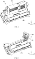
- the development unit 100 may include the development processor 200 and the developer container 300 as illustrated in FIGs. 1 to 4 , for example.
- the developer container 300 is attachable to the development processor 200 in a detachable manner.
- FIG. 2 illustrates a state in which the developer container 300 is detached from the development processor 200.
- the development processor 200 may correspond to the development processing unit according to the first example embodiment of the technology.
- the development processor 200 may correspond to an "attached unit" in one specific but non-limiting embodiment of the technology.
- the development processor 200 may attach, onto an electrostatic latent image, a developer 314 illustrated in FIG. 5 that is fed from the developer container 300 which will be described later.
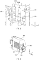
- FIG. 5 illustrates a plan configuration in an YZ plane of each of the development processor 200 and the developer container 300.
- FIG. 5 illustrates a state in which the developer container 300 is attached to the development processor 200.
- FIG. 5 omits illustration of the engaged section 201.
- the photosensitive drum 212 may be an organic photoreceptor that includes a cylindrical electrically-conductive supporting body and a photoconductive layer, for example.
- the photoconductive layer may cover an outer peripheral surface of the electrically-conductive supporting body.
- the photosensitive drum 212 may be rotatable with a drive source such as a motor.
- the electrically-conductive supporting body may be a metal pipe that includes a metal material such as aluminum, for example.
- the photoconductive layer may be a stack that includes layers including an electric charge generating layer and an electric charge transfer layer, for example.
- the housing 211 may have an opening 219 from which the photosensitive drum 212 is to be partially exposed, for example.
- the LED head 214 may be an exposure device that performs exposure of the surface of the photosensitive drum 212, and thereby forms an electrostatic latent image on the surface of the photosensitive drum 212.
- the LED head 214 may include an LED device and a lens array, for example.
- the LED device and the lens array may be so disposed that light (irradiation light) outputted from the LED device is imaged on the surface of the photosensitive drum 212.
- the housing 211 may have an opening 220 that guides the light outputted from the LED head 214 to the photosensitive drum 212, for example.
- the feeding roller 217 may include a metal shaft and an electrically-semiconductive foamed silicone sponge layer that covers an outer peripheral surface of the metal shaft, for example.
- the feeding roller 217 may be rotatable with a drive source such as a motor.
- the feeding roller 217 may feed the developer 314 to the surface of the developing roller 215 while being in contact with the developing roller 215 in a slidable manner.
- the developing blade 218 may control the thickness of the developer 314 fed on the surface of the developing roller 215.
- the developing blade 218 may be so disposed as to be away from the developing roller 215 with a predetermined spacing in between.
- the thickness of the developer 314 may be controlled on the basis of the predetermined spacing.
- the developing blade 218 may include a metal material such as stainless steel, for example.
- the developer 314 may be so-called toner, for example.
- a configuration of the developer 314 such as a color of the developer 314 is not particularly limited.
- the development processor 200 may have the engaged section 201 that is provided in part of the housing 211, for example.
- the engaged section 201 may include the insertion regulating member 204 and a fixing member 206, for example.
- the insertion regulating member 204 may be disposed inside an insertion chamber 203, for example.
- the fixing member 206 may be disposed outside the insertion chamber 203, for example.
- FIG. 6 illustrates a state in which the fixing member 206 is away from the insertion regulating member 204 for the sake of easier understanding of the configuration of the insertion regulating member 204.
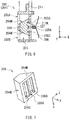
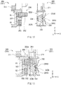
- the insertion regulating member 204 may have a function of regulating (permitting or prohibiting) insertion of the protrusion 302 into the insertion chamber 203, which may be called an insertion regulating function. Accordingly, the insertion regulating member 204 may be movable from an initial position to a regulating position in a direction (a Z direction) intersecting an insertion direction (an X direction) of the protrusion 302. Such a movement of the insertion regulating member 204 may be performed in response to the insertion of the protrusion 302 into the insertion chamber 203.
- the "insertion direction of the protrusion 302" is a direction in which the protrusion 302 is inserted, and is also referred to as a protruding direction or an extending direction of the protrusion 302 in other words.
- the insertion regulating member 204 may prevent the protrusion 302 from being inserted into the insertion chamber 203 from the opening 202B after the protrusion 302 is inserted into the insertion chamber 203 from the opening 202A, i.e., the insertion regulating member 204 may prohibit the insertion of the protrusion 302 into the insertion chamber 203 from the opening 202B.
- the insertion regulating member 204 may be pressed in the Z direction by the protrusion 302 when the protrusion 302 is inserted into the insertion chamber 203 from the opening 202A, for example.
- the Z direction may correspond to a downward direction in FIG. 6 , for example.
- the insertion regulating member 204 may be therefore moved from the initial position to the regulating position in the downward direction.
- a three-dimensional shape of the insertion regulating member 204 is not particularly limited and may be any three-dimensional shape that includes the foregoing pair of sloped surfaces 204M.
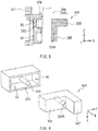
- the three-dimensional shape of the insertion regulating member 204 may be a quadrangular prism shape having top and bottom surfaces that are each a substantially-trapezoidal shape as illustrated in FIG. 7 , for example.
- the fixing member 206 may be inserted into one of the fixing depressions 205B and 205C when the insertion regulating member 204 is located at the regulating position, for example.
- the insertion regulating member 204 located at the regulating position may be thus fixed fully by the fixing member 206.
- the developer container 300 may include the engaging section 301 that is provided in part of the housing 311, for example.
- the engaging section 301 may include a partially-protruding part, i.e., the protrusion 302, for example.
- the protrusion 302 may be disposed in one of two protrusion regions R1 and R2.
- the "two protrusion regions R1 and R2" may each be a position in which the protrusion 302 is disposed. Positions of the two protrusion regions R1 and R2 may correspond to the respective positions of the two openings 202A and 202B provided in the development processor 200.
- the protrusion 302 may correspond to a "protrusion" in one specific but non-limiting embodiment of the technology.
- the protrusion region R1 may correspond to a "first protrusion region” in one specific but non-limiting embodiment of the technology.
- the protrusion region R2 may correspond to a "second protrusion region” in one specific but non-limiting embodiment of the technology.
- the engaging section 301 may have a protrusion depression 303 in a region covering from the protrusion region R1 to the protrusion region R2, for example.
- the engaging section 301 may include a protrusion member 304, for example.
- the protrusion member 304 may be insertable into the protrusion depression 303, for example.
- One reason why the protrusion member 304 is described as being "insertable into the protrusion depression 303" is that the protrusion member 304 may be inserted into the protrusion depression 303 on an as-needed basis, i.e., the protrusion member 304 may be attachable to and detachable from the protrusion depression 303 on an as-needed basis.
- FIG. 8 illustrates a state where the protrusion member 304 is away from the protrusion depression 303 for the sake of easier understanding of a relationship between the protrusion depression 303 and the protrusion member 304.
- the embedded part 305 may be contained in the protrusion depression 303, and the protrusion 302 may protrude from the protrusion depression 303. It is thus possible to fill the protrusion depression 303 with part of the protrusion member 304, i.e., the embedded part 305, and to cause only other part of the protrusion member 304, i.e., only the protrusion 302 to protrude from the protrusion depression 303.
- a three-dimensional shape of the alignment projection 306 is not particularly limited.
- the three-dimensional shape of the alignment projection 306 may be a cylindrical shape, a prism shape, or any other shape, for example.
- Non-limiting examples of the prism shape may include a quadrangular prism shape and a pentagonal prism shape.
- a three-dimensional shape of the alignment opening 304K is not particularly limited and may be any shape that allows the alignment projection 306 to be inserted into the alignment opening 304K.
- the three-dimensional shape of the alignment opening 304K may be the same as the three-dimensional shape of the alignment projection 306 described above, or may be different from the three-dimensional shape of the alignment projection 306 described above.
- the protrusion member 304 may include both the protrusion 302 and the embedded part 305. One reason for this is to prevent the developer container 300 from being unattachable to the development processor 200 unintentionally.
- the following description refers, as an example, to an attachment regulating operation with the engaging section 301 in the first row and the engaged section 201 in the first row.
- the insertion regulating member 204 may be fully fixed by the fixing member 206 as described above. Therefore, a state in which the insertion regulating member 204 is located at the regulating position may be maintained even after the developer container 300 is detached from the development processor 200.
- the charging roller 213 in the development processor 200 may apply a direct-current voltage to the surface of the photosensitive drum 212 while rotating, in response to the rotation of the photosensitive drum 212.
- the surface of the photosensitive drum 212 may be thereby electrically charged in an even manner.
- the developing roller 215 may rotate while being so pressed against the feeding roller 217 as to be in contact with the feeding roller 217, after application of a voltage to the development roller 215. This may cause the developer 314 fed on the surface of the feeding roller 217 to be adsorbed onto the surface of the developing roller 215.
- the developer 314 may be therefore conveyed by utilizing the rotation of the developing roller 215.
- part of the developer 314 adsorbed onto the surface of the developing roller 215 may be removed by the developing blade 218. This may allow the thickness of the developer 314 adsorbed onto the surface of the developing roller 215 to be even.
- the development unit 100 may include the attached unit (the development processor 200) having the engaged section 201 and the attachable unit (the developer container 300) having the engaging section 301.
- the state of the engaged section 201 changes in response to the engagement of the engaging section 301.
- the state of the engaged section 201 upon the engagement of the engaging section 301 i.e., the state of the engaged section 201 after the change is maintained even after the engaging section 301 is detached from the engaged section 201.
- an inappropriate developer container 300 is prevented from being attached to the development processor 200 after the insertion regulating member 204 has moved to the regulating position as described above. It is therefore possible to prevent the developer container 300 from being mistakenly attached to the development processor 200.
- the insertion regulating member 204 is fixed temporarily and fully by the fixing member 206 under the conditions that: the insertion regulating member 204 has the fixing depression 205A having a relatively-smaller depth and the fixing depressions 205B and 205C each having a relatively-greater depth; and the fixing member 206 is insertable into any of the fixing depressions 205A to 205C. It is therefore possible to achieve a higher effect.
- the fixing member 206 that has been inserted into the fixing depression 205A it is easier for the fixing member 206 that has been inserted into the fixing depression 205A to be removed from the fixing depression 205A on an as-needed basis when the inner wall surface, of the insertion regulating member 204, inside the fixing depression 205A is so sloped that the depth of the fixing depression 205A gradually increases in a direction of being closer to the fixing depression 205A from each of the pair of fixing depressions 205B and 205C. It is therefore possible to achieve a higher effect.
- the insertion regulating member 226 may have a function of regulating (permitting or prohibiting) insertion of the protrusion 302 into the insertion chamber 224, which may be called an insertion regulating function.
- the insertion regulating member 225 may be so pressed by the inserted protrusion 302 as to move backward.
- the insertion regulating member 226 may be so pressed by the movement controlling member 228 as to move forward, thereby exhibiting the foregoing insertion control function.
- the insertion regulating member 226 may be thus movable in the insertion direction (the X direction) of the protrusion 302.
- the insertion regulating member 226 may be movable from the initial position to the regulating position.
- which of the insertion regulating members 225 and 226 is pressed by the protrusion 302 may depend on whether the protrusion 302 is inserted into the insertion chamber 223 from the opening 221 or whether the protrusion 302 is inserted into the insertion chamber 224 from the opening 222.
- a three-dimensional shape of the fixing depression 227UB may be a triangular prism shape having an upper surface and a lower surface (a bottom surface) that each has an isosceles triangle shape or any other shape, for example.
- One reason for this is that it is easier for the projection 225P to be removed from the fixing depression 227UB on an as-needed basis upon the movement (the forward movement or the backward movement) of the insertion regulating member 225 located at the initial position. This allows the insertion regulating member 225 to move more easily and more stably.
- each of the foregoing sloped surfaces may include only a flat surface, include only a curved surface, or include both the flat surface and the curved surface.
- the number of the engaged section 220 provided in the development processor 200 may be one, or two or more, as with the number of the engaging section 301 provided in the developer container 300.
- the number of the engaged section 220 and the number of the engaging section 301 may be preferably equal to each other.
- FIG. 14 illustrates an example case where the number of the engaged section 220 is two, and the two engaged sections 220 are disposed in the Z direction.
- An operation of the development unit 100 according to the present example embodiment may be similar to the operation of the development unit 100 according to the first example embodiment except that the development unit 100 according to the present example embodiment may perform the attachment regulating operation by the following procedure.
- the projection 226P may be inserted into the fixing depression 227UD when the insertion regulating member 226 is located at the initial position.
- the height of the projection 226P may gradually increase in the insertion direction of the protrusion 302
- the depth of the fixing depression 227UD gradually increases in the insertion direction of the protrusion 302 and thereafter gradually decreases in the insertion direction of the protrusion 302. It may be therefore easy for the projection 226P to be removed from the fixing depression 227UD.
- the insertion regulating member 226 may be thus fixed temporarily by the projection 226P in accordance with the insertion of the projection 226P into the fixing depression 227UD.
- the engaged section 220 includes the insertion regulating members 225 and 226; and one of the insertion regulating members 225 and 226 is movable from the initial position to the regulating position.
- the movement controlling member 228 having the following configuration is provided.
- each of the insertion regulating members 225 and 226 is suppressed when the separating member 227 has the two fixing depressions 227UA and 227UB into which the projection 225P is to be inserted and also has the two fixing depressions 227UC and 227UD into which the projection 226P is to be inserted. It is therefore possible to achieve a higher effect.
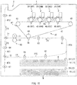
- the image forming apparatus described below may be a full-color printer using an electrophotographic method, for example.
- the image forming apparatus may form an image on a surface of a medium M, for example.
- a material of the medium M is not particularly limited. However, the material of the medium M may be one or more of materials such as paper and a film.
- the one or more trays 10 each may contain the medium M.
- the one or more trays 10 may each be attached to the housing 1 detachably, for example.
- One or more trays 10 may each contain a plurality of media M in a stacked state, for example.
- the media M may be picked out one by one from the corresponding tray 10 by the corresponding feeding roller 20.
- the one or more developing units 30 each may perform a development process with a developer.
- the one or more developing units 30 each may have a configuration similar to that of the development unit according to any one of the foregoing example embodiments of the technology.
- the one or more developing units 30 each may have a configuration similar to that of the development unit 100 according to the foregoing first example embodiment, or may have a configuration similar to that of the development unit 100 according to the foregoing second example embodiment.
- the conveying path switching guides 71 and 72 each may switch the conveying direction of the medium M depending on conditions such as a manner in which an image is formed on the medium M.
- the conditions on the manner in which an image is formed on the medium M may include whether an image is formed on only one surface of the medium M and whether images are formed on both surfaces of the medium M, for example.
- the primary transfer process may involve application of a voltage to the primary transfer roller 45Y.
- the primary transfer roller 45Y may be so pressed against the photosensitive drum as to be in contact with the photosensitive drum with the intermediate transfer belt 41 in between. Accordingly, the yellow developer that has been attached onto the surface of the photosensitive drum, i.e., onto the electrostatic latent image in the foregoing developing process may be transferred onto the intermediate transfer belt 41.
- the intermediate transfer belt 41 onto which the yellow developer is transferred may continue to travel in the direction indicated by the arrow F5.
- the developing process and the primary transfer process may be sequentially performed by the developing units 30M, 30C, and 30K, and the primary transfer rollers 45M, 45C, and 45K.
- the procedure of the developing process and the primary transfer process performed by the developing units 30M, 30C, and 30K, and the primary transfer rollers 45M, 45C, and 45K may be similar to that performed by the developing unit 30Y and the primary transfer roller 45Y described above.
- the developers of the respective colors may be sequentially transferred onto the intermediate transfer belt 41 in such a manner. The developer images of the respective colors may be thus formed on the intermediate transfer belt 41.
- the procedure of conveying the medium M may vary depending on a manner in which an image is formed on the surface of the medium M, which is not described in detail in this description.
- Unnecessary remains of the developer may be present on the surface of the photosensitive drum in the developing unit 30Y.
- the unnecessary remains of the developer may be part of the developer that has been used in the primary transfer process, which may be the developer that has remained on the surface of the photosensitive drum without being transferred onto the intermediate transfer belt 41, for example.
- the foregoing cleaning process using the cleaning blade may be performed similarly in each of the developing units 30M, 30C, and 30K.
Landscapes
- Physics & Mathematics (AREA)
- General Physics & Mathematics (AREA)
- Engineering & Computer Science (AREA)
- Computer Vision & Pattern Recognition (AREA)
- Electrophotography Configuration And Component (AREA)
- Dry Development In Electrophotography (AREA)
Applications Claiming Priority (1)
| Application Number | Priority Date | Filing Date | Title |
|---|---|---|---|
| JP2016070201A JP6546559B2 (ja) | 2016-03-31 | 2016-03-31 | 現像処理装置、現像装置および画像形成装置 |
Publications (2)
| Publication Number | Publication Date |
|---|---|
| EP3226077A2 true EP3226077A2 (de) | 2017-10-04 |
| EP3226077A3 EP3226077A3 (de) | 2017-12-20 |
Family
ID=58358445
Family Applications (1)
| Application Number | Title | Priority Date | Filing Date |
|---|---|---|---|
| EP17161478.7A Withdrawn EP3226077A3 (de) | 2016-03-31 | 2017-03-17 | Entwicklerhaltige einheit, entwicklungsverarbeitungseinheit, entwicklungseinheit und bilderzeugungsvorrichtung |
Country Status (4)
| Country | Link |
|---|---|
| US (1) | US10108140B2 (de) |
| EP (1) | EP3226077A3 (de) |
| JP (1) | JP6546559B2 (de) |
| CN (1) | CN107272367A (de) |
Families Citing this family (1)
| Publication number | Priority date | Publication date | Assignee | Title |
|---|---|---|---|---|
| JP7047541B2 (ja) | 2018-03-30 | 2022-04-05 | ブラザー工業株式会社 | 現像カートリッジ |
Citations (1)
| Publication number | Priority date | Publication date | Assignee | Title |
|---|---|---|---|---|
| JP2006099132A (ja) | 2005-11-24 | 2006-04-13 | Oki Data Corp | 電子写真プリンタ |
Family Cites Families (24)
| Publication number | Priority date | Publication date | Assignee | Title |
|---|---|---|---|---|
| US4561567A (en) * | 1984-01-20 | 1985-12-31 | Pitney Bowes Inc. | Toner loading apparatus |
| JPS60229072A (ja) * | 1984-04-27 | 1985-11-14 | Toshiba Corp | 現像装置 |
| JPS634252A (ja) * | 1986-06-24 | 1988-01-09 | Canon Inc | プロセスカ−トリツジ及びこのカ−トリツジを使用する画像形成装置 |
| JPH01205175A (ja) * | 1988-02-12 | 1989-08-17 | Nec Corp | 消耗品カートリッジ |
| DE69207229T2 (de) * | 1991-03-01 | 1996-06-20 | Canon Kk | Bilderzeugungssystem und eine in diesem eingesetzte entfernbare Arbeitseinheit |
| JPH06202403A (ja) | 1992-12-24 | 1994-07-22 | Mita Ind Co Ltd | 画像形成回数カウンタのリセット機構 |
| US5530531A (en) * | 1995-03-15 | 1996-06-25 | Hewlett-Packard Company | Multiple cartridge keying apparatus |
| US5848338A (en) * | 1997-01-17 | 1998-12-08 | Mita Industrial Co., Ltd. | Toner replenishing device and toner cartridge for use therein |
| JP2000010392A (ja) * | 1998-06-18 | 2000-01-14 | Ricoh Co Ltd | トナーボトル用キャップ |
| TWI272461B (en) * | 1998-12-22 | 2007-02-01 | Ricoh Kk | Toner container and image forming method and apparatus using the same |
| JP3050872B1 (ja) * | 1999-07-12 | 2000-06-12 | 松下電送システム株式会社 | 転写ユニット及びそれを備えた記録装置 |
| US7155138B2 (en) * | 2003-12-22 | 2006-12-26 | Canon Kabushiki Kaisha | Developer supply container |
| JP2008020605A (ja) * | 2006-07-12 | 2008-01-31 | Oki Data Corp | 現像装置及び画像形成装置 |
| JP4458104B2 (ja) * | 2007-02-28 | 2010-04-28 | ブラザー工業株式会社 | 画像形成装置 |
| EP1950625B1 (de) * | 2007-02-28 | 2014-10-29 | Brother Kogyo Kabushiki Kaisha | Bilderzeugungsvorrichtung mit Entwicklungseinheit |
| JP5238434B2 (ja) * | 2008-09-30 | 2013-07-17 | 京セラドキュメントソリューションズ株式会社 | 現像装置及びそれを備えた画像形成装置 |
| JP2012103427A (ja) * | 2010-11-09 | 2012-05-31 | Ricoh Co Ltd | 画像形成装置 |
| JP5741808B2 (ja) * | 2011-01-20 | 2015-07-01 | 株式会社リコー | 現像剤量検知装置及び画像形成装置 |
| JP5182402B2 (ja) * | 2011-08-31 | 2013-04-17 | ブラザー工業株式会社 | カートリッジ |
| JP5919705B2 (ja) * | 2011-09-29 | 2016-05-18 | ブラザー工業株式会社 | 画像形成装置 |
| JP5822816B2 (ja) * | 2012-11-20 | 2015-11-24 | 株式会社沖データ | 現像剤収容体、現像剤収容体保持ユニット、及び画像形成装置 |
| KR101580224B1 (ko) * | 2014-03-12 | 2015-12-24 | 삼성전자주식회사 | 카트리지 및 이를 채용한 전자사진방식 화상형성장치 |
| TWM486074U (zh) * | 2014-03-24 | 2014-09-11 | Avision Inc | 具結構卡合之成像裝置 |
| JP6671884B2 (ja) * | 2014-10-14 | 2020-03-25 | キヤノン株式会社 | 画像形成装置 |
-
2016
- 2016-03-31 JP JP2016070201A patent/JP6546559B2/ja not_active Expired - Fee Related
-
2017
- 2017-03-16 US US15/460,284 patent/US10108140B2/en not_active Expired - Fee Related
- 2017-03-17 EP EP17161478.7A patent/EP3226077A3/de not_active Withdrawn
- 2017-03-20 CN CN201710164722.4A patent/CN107272367A/zh active Pending
Patent Citations (1)
| Publication number | Priority date | Publication date | Assignee | Title |
|---|---|---|---|---|
| JP2006099132A (ja) | 2005-11-24 | 2006-04-13 | Oki Data Corp | 電子写真プリンタ |
Also Published As
| Publication number | Publication date |
|---|---|
| EP3226077A3 (de) | 2017-12-20 |
| US10108140B2 (en) | 2018-10-23 |
| JP6546559B2 (ja) | 2019-07-17 |
| US20170285561A1 (en) | 2017-10-05 |
| JP2017181843A (ja) | 2017-10-05 |
| CN107272367A (zh) | 2017-10-20 |
Similar Documents
| Publication | Publication Date | Title |
|---|---|---|
| US7272339B2 (en) | Process cartridge including first and second frames and separating member moving the second frame to a separated position and image forming apparatus detachably mounting the cartridge | |
| EP2972592B1 (de) | Tonerbehälter und bilderzeugungsvorrichtung | |
| US8687993B2 (en) | Charging device, image forming assembly and image forming apparatus using the charging device | |
| US20070177894A1 (en) | Image forming apparatus having belt unit | |
| EP3396465A1 (de) | Entwicklungsvorrichtung | |
| US9599931B2 (en) | Floating toner port interface with a replaceable unit of an electrophotographic image forming device | |
| JP7047633B2 (ja) | 定着装置および画像形成装置 | |
| US20160282759A1 (en) | Developer replenishment device and image forming apparatus | |
| EP2680086B1 (de) | Aufbewahrungskörper für Entwickler, Bilderzeugungseinheit und Bilderzeugungsvorrichtung | |
| US8045897B2 (en) | Developing device | |
| JP7187166B2 (ja) | 画像形成装置 | |
| US7907875B2 (en) | Developer cartridge and developing device | |
| EP3226077A2 (de) | Entwicklerhaltige einheit, entwicklungsverarbeitungseinheit, entwicklungseinheit und bilderzeugungsvorrichtung | |
| US9568858B2 (en) | Developing unit, image forming unit, and image forming apparatus | |
| US20160320744A1 (en) | Developing device insertion/extraction structure and image forming apparatus | |
| US9958805B2 (en) | Image forming apparatus | |
| US10942467B1 (en) | Charging device, image carrying unit, and image forming apparatus | |
| JP6646246B2 (ja) | 現像装置、プロセスカートリッジ、及び、画像形成装置 | |
| US11506995B2 (en) | Developing device and image forming apparatus | |
| US8010015B2 (en) | Charger and image forming apparatus using the charger | |
| JP4793466B2 (ja) | 画像形成装置 | |
| US10048620B1 (en) | Developing device and image forming apparatus therewith | |
| JP2019045747A (ja) | 帯電ローラ軸受保持機構 | |
| CN110007577A (zh) | 调色剂盒及图像形成装置 | |
| KR20190038360A (ko) | 현상 장치 및 화상 형성 장치 |
Legal Events
| Date | Code | Title | Description |
|---|---|---|---|
| PUAI | Public reference made under article 153(3) epc to a published international application that has entered the european phase |
Free format text: ORIGINAL CODE: 0009012 |
|
| STAA | Information on the status of an ep patent application or granted ep patent |
Free format text: STATUS: THE APPLICATION HAS BEEN PUBLISHED |
|
| AK | Designated contracting states |
Kind code of ref document: A2 Designated state(s): AL AT BE BG CH CY CZ DE DK EE ES FI FR GB GR HR HU IE IS IT LI LT LU LV MC MK MT NL NO PL PT RO RS SE SI SK SM TR |
|
| AX | Request for extension of the european patent |
Extension state: BA ME |
|
| PUAL | Search report despatched |
Free format text: ORIGINAL CODE: 0009013 |
|
| AK | Designated contracting states |
Kind code of ref document: A3 Designated state(s): AL AT BE BG CH CY CZ DE DK EE ES FI FR GB GR HR HU IE IS IT LI LT LU LV MC MK MT NL NO PL PT RO RS SE SI SK SM TR |
|
| AX | Request for extension of the european patent |
Extension state: BA ME |
|
| RIC1 | Information provided on ipc code assigned before grant |
Ipc: G03G 21/18 20060101ALI20171114BHEP Ipc: G03G 21/16 20060101AFI20171114BHEP |
|
| STAA | Information on the status of an ep patent application or granted ep patent |
Free format text: STATUS: REQUEST FOR EXAMINATION WAS MADE |
|
| 17P | Request for examination filed |
Effective date: 20180620 |
|
| RBV | Designated contracting states (corrected) |
Designated state(s): AL AT BE BG CH CY CZ DE DK EE ES FI FR GB GR HR HU IE IS IT LI LT LU LV MC MK MT NL NO PL PT RO RS SE SI SK SM TR |
|
| STAA | Information on the status of an ep patent application or granted ep patent |
Free format text: STATUS: EXAMINATION IS IN PROGRESS |
|
| STAA | Information on the status of an ep patent application or granted ep patent |
Free format text: STATUS: THE APPLICATION HAS BEEN WITHDRAWN |
|
| 17Q | First examination report despatched |
Effective date: 20210406 |
|
| 18W | Application withdrawn |
Effective date: 20210412 |