EP3226097B1 - Axialventil zur kontrolle des differnezdrucks zwischen einem vorlauf- und einem rücklaufzweig einer hydraulischen schaltung - Google Patents
Axialventil zur kontrolle des differnezdrucks zwischen einem vorlauf- und einem rücklaufzweig einer hydraulischen schaltung Download PDFInfo
- Publication number
- EP3226097B1 EP3226097B1 EP17159910.3A EP17159910A EP3226097B1 EP 3226097 B1 EP3226097 B1 EP 3226097B1 EP 17159910 A EP17159910 A EP 17159910A EP 3226097 B1 EP3226097 B1 EP 3226097B1
- Authority
- EP
- European Patent Office
- Prior art keywords
- fluid
- chamber
- tubular body
- return
- valve
- Prior art date
- Legal status (The legal status is an assumption and is not a legal conclusion. Google has not performed a legal analysis and makes no representation as to the accuracy of the status listed.)
- Active
Links
Images


Classifications
-
- G—PHYSICS
- G05—CONTROLLING; REGULATING
- G05D—SYSTEMS FOR CONTROLLING OR REGULATING NON-ELECTRIC VARIABLES
- G05D16/00—Control of fluid pressure
- G05D16/04—Control of fluid pressure without auxiliary power
- G05D16/06—Control of fluid pressure without auxiliary power the sensing element being a flexible membrane, yielding to pressure, e.g. diaphragm, bellows, capsule
- G05D16/0608—Control of fluid pressure without auxiliary power the sensing element being a flexible membrane, yielding to pressure, e.g. diaphragm, bellows, capsule the controller being mounted within the flow path and having slidable elements
-
- F—MECHANICAL ENGINEERING; LIGHTING; HEATING; WEAPONS; BLASTING
- F15—FLUID-PRESSURE ACTUATORS; HYDRAULICS OR PNEUMATICS IN GENERAL
- F15B—SYSTEMS ACTING BY MEANS OF FLUIDS IN GENERAL; FLUID-PRESSURE ACTUATORS, e.g. SERVOMOTORS; DETAILS OF FLUID-PRESSURE SYSTEMS, NOT OTHERWISE PROVIDED FOR
- F15B13/00—Details of servomotor systems ; Valves for servomotor systems
- F15B13/02—Fluid distribution or supply devices characterised by their adaptation to the control of servomotors
- F15B13/04—Fluid distribution or supply devices characterised by their adaptation to the control of servomotors for use with a single servomotor
- F15B13/0416—Fluid distribution or supply devices characterised by their adaptation to the control of servomotors for use with a single servomotor with means or adapted for load sensing
- F15B13/0417—Load sensing elements; Internal fluid connections therefor; Anti-saturation or pressure-compensation valves
-
- F—MECHANICAL ENGINEERING; LIGHTING; HEATING; WEAPONS; BLASTING
- F15—FLUID-PRESSURE ACTUATORS; HYDRAULICS OR PNEUMATICS IN GENERAL
- F15B—SYSTEMS ACTING BY MEANS OF FLUIDS IN GENERAL; FLUID-PRESSURE ACTUATORS, e.g. SERVOMOTORS; DETAILS OF FLUID-PRESSURE SYSTEMS, NOT OTHERWISE PROVIDED FOR
- F15B13/00—Details of servomotor systems ; Valves for servomotor systems
- F15B13/02—Fluid distribution or supply devices characterised by their adaptation to the control of servomotors
- F15B13/04—Fluid distribution or supply devices characterised by their adaptation to the control of servomotors for use with a single servomotor
- F15B13/042—Fluid distribution or supply devices characterised by their adaptation to the control of servomotors for use with a single servomotor operated by fluid pressure
- F15B13/0426—Fluid distribution or supply devices characterised by their adaptation to the control of servomotors for use with a single servomotor operated by fluid pressure with fluid-operated pilot valves, i.e. multiple stage valves
-
- G—PHYSICS
- G05—CONTROLLING; REGULATING
- G05D—SYSTEMS FOR CONTROLLING OR REGULATING NON-ELECTRIC VARIABLES
- G05D16/00—Control of fluid pressure
- G05D16/028—Controlling a pressure difference
-
- G—PHYSICS
- G05—CONTROLLING; REGULATING
- G05D—SYSTEMS FOR CONTROLLING OR REGULATING NON-ELECTRIC VARIABLES
- G05D16/00—Control of fluid pressure
- G05D16/04—Control of fluid pressure without auxiliary power
- G05D16/06—Control of fluid pressure without auxiliary power the sensing element being a flexible membrane, yielding to pressure, e.g. diaphragm, bellows, capsule
- G05D16/063—Control of fluid pressure without auxiliary power the sensing element being a flexible membrane, yielding to pressure, e.g. diaphragm, bellows, capsule the sensing element being a membrane
- G05D16/0644—Control of fluid pressure without auxiliary power the sensing element being a flexible membrane, yielding to pressure, e.g. diaphragm, bellows, capsule the sensing element being a membrane the membrane acting directly on the obturator
- G05D16/0655—Control of fluid pressure without auxiliary power the sensing element being a flexible membrane, yielding to pressure, e.g. diaphragm, bellows, capsule the sensing element being a membrane the membrane acting directly on the obturator using one spring-loaded membrane
- G05D16/0661—Control of fluid pressure without auxiliary power the sensing element being a flexible membrane, yielding to pressure, e.g. diaphragm, bellows, capsule the sensing element being a membrane the membrane acting directly on the obturator using one spring-loaded membrane characterised by the loading mechanisms of the membrane
-
- G—PHYSICS
- G05—CONTROLLING; REGULATING
- G05D—SYSTEMS FOR CONTROLLING OR REGULATING NON-ELECTRIC VARIABLES
- G05D16/00—Control of fluid pressure
- G05D16/04—Control of fluid pressure without auxiliary power
- G05D16/10—Control of fluid pressure without auxiliary power the sensing element being a piston or plunger
- G05D16/103—Control of fluid pressure without auxiliary power the sensing element being a piston or plunger the sensing element placed between the inlet and outlet
-
- F—MECHANICAL ENGINEERING; LIGHTING; HEATING; WEAPONS; BLASTING
- F15—FLUID-PRESSURE ACTUATORS; HYDRAULICS OR PNEUMATICS IN GENERAL
- F15B—SYSTEMS ACTING BY MEANS OF FLUIDS IN GENERAL; FLUID-PRESSURE ACTUATORS, e.g. SERVOMOTORS; DETAILS OF FLUID-PRESSURE SYSTEMS, NOT OTHERWISE PROVIDED FOR
- F15B2211/00—Circuits for servomotor systems
- F15B2211/80—Other types of control related to particular problems or conditions
- F15B2211/88—Control measures for saving energy
-
- Y—GENERAL TAGGING OF NEW TECHNOLOGICAL DEVELOPMENTS; GENERAL TAGGING OF CROSS-SECTIONAL TECHNOLOGIES SPANNING OVER SEVERAL SECTIONS OF THE IPC; TECHNICAL SUBJECTS COVERED BY FORMER USPC CROSS-REFERENCE ART COLLECTIONS [XRACs] AND DIGESTS
- Y10—TECHNICAL SUBJECTS COVERED BY FORMER USPC
- Y10T—TECHNICAL SUBJECTS COVERED BY FORMER US CLASSIFICATION
- Y10T137/00—Fluid handling
- Y10T137/3367—Larner-Johnson type valves; i.e., telescoping internal valve in expanded flow line section
- Y10T137/3476—Internal servo-motor with internal pilot valve
- Y10T137/353—Pilot controlled passage in nose or needle
Definitions
- the present invention relates to an axial valve for controlling the differential pressure between a delivery branch and a return branch of a hydraulic circuit, in particular for heating and/or cooling. It is known in the technical sector relating to the hydraulic distribution of fluids among several users that the differential pressure between the fluid delivery and return is subject to fluctuations due to variations in the head along the hydraulic circuit and that, consequently, there exists the need to keep said pressure differential as constant as possible in the event of said fluctuations.
- DPCVs Different Pressure Control Valves
- the shank of the closing member which is arranged perpendicularly relative to the surface of the membrane, is integrally connected to the latter so that displacements of the membrane in either direction produce corresponding axial displacements of the closing member which open/close the valve.
- the membrane is arranged inside a measurement chamber which is divided into two half-chambers so that the membrane is acted on:
- this device should have small dimensions, be easy and inexpensive to produce and assemble and be able to be easily installed at any user location, even by non-specialized users.
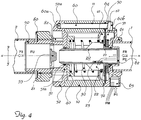
- a first example of a valve according to the invention comprises essentially:
- baffle 51 which in the example is joined to the pipefitting 50 and which is coaxially slidable on the tubular body 20 via a coaxial opening 51a and provided with an axially extending annular edge 52 and having a diameter preferably corresponding to the diameter on which the axial seats 11 of the annular body 10 are positioned; said diameter is provided with female-thread seats 52a for mating with the thread 60a of locking screws 60b, the heads 60b of which bear against:
- Figs. 5 and 6 show a second embodiment of the valve according to the invention which comprises:
- One or more radial holes 161b are formed in the outer cylindrical surface 161c of the torus-shaped body;
- O-ring seals are arranged between the flange 140 and the annular body 110 and between the latter and membrane-pressing element 170 and around the adjustment pins 182.
- valve offers an axially extending assembly which is simple and inexpensive to assemble and apply to hydraulic circuits, preferably intended for heating/cooling, or preferably to fluid distribution headers, and how adjustment of the valve calibration (namely setting of the differential pressure value which is to be maintained between the delivery branch and the return branch), which may be achieved via the spring, without involving the closing member, does not alter the adjustment process or the responsiveness of the valve to variations in the pressure differential. Calibration may be performed in situ depending on the characteristics of the hydraulic circuit.
- Figs. 6 and 7 include in fact only the O-ring seal which is arranged between the flange 140 and the annular body 110, said elements not being subject to axial movement and therefore not giving rise to wear.
Landscapes
- Physics & Mathematics (AREA)
- Engineering & Computer Science (AREA)
- Fluid Mechanics (AREA)
- General Physics & Mathematics (AREA)
- Automation & Control Theory (AREA)
- Mechanical Engineering (AREA)
- General Engineering & Computer Science (AREA)
- Safety Valves (AREA)
Claims (5)
- Axial-Differenzdruckregelventil (DPCV) zum Steuern und/oder Regeln des Differenzdrucks zwischen Zweigen eines Hydraulikkreises, wobei folgendes für das Ventil definiert ist:- eine Längsachse (X-X) die parallel zu eine Strömungsrichtung eines Fluids verläuft,- ein axialer Einlass (61; 111) für ein Rücklauffluid (FR) unter Druck (P2), der von einem Rücklaufzweig (1) des Hydraulikkreises (2) gespeist wird,- ein Radialeinlass (63;163) für ein Fluid (FM) unter Druck P1, der von einem Förderzweig des gleichen Hydraulikkreises (2) gespeist wird,- einen Axialausgang (50;150) in Richtung des Hydraulikkreises (2) für ein Fluid (FU) unter kompensiertem Druck (P3),wobei das Ventil- einen ringförmigen Körper (10;110);- einen rohrförmigen Körper (20; 120; 220), der koaxial in den ringförmigen Körper (10; 110) eingesetzt ist, wobei das Ende des rohrförmigen Körpers (20; 120; 220), das Axial auf die Seite des Axialeinlasses für das Rücklauffluid (FR) des Ventils gerichtet ist, eine ringförmige Scheibe (21; 121; 221) aufweist;- eine Feder (30; 130), die koaxial außerhalb des rohrförmigen Körpers angeordnet ist und axial durch die Scheibe (21; 121; 221) auf der Einlassseite (FR) und durch einen Anschlagflansch (40; 140) auf der Auslassseite (FU) in Position gehalten ist;- eine Rohrverbindung (50; 150) zur Verbindung mit dem Hydraulikkreis (2);- ein koaxiales Verschlusselement (55; 155) zum Schließen einer Auslassöffnung für den Auslass des Fluids aus dem rohrförmigen Körper (20; 120; 220), das zwischen letzterem und der Rohrverbindung (50; 150) angeordnet ist;- eine Feststellringmutter (80; 180), die ausgangsseitig auf ein Außengewinde (81; 181) der Rohrverbindung (50; 150) aufgeschraubt werden kann und koaxial darauf wirkt, um diese dichtend zu schließen;- eine erste Kammer (C1) in fluiddynamischer Verbindung mit dem Einlass für das Rücklauffluid (FR) unter Druck (P2), der von dem Rücklaufzweig (1) gespeist wird;- eine zweite Kammer (C2), die dazu ausgelegt ist mit dem Förderfluid (FM) unter Druck P1 gefüllt zu werden;- Dichtungstrennmittel (70; 170; 221, 221a), die zwischen der ersten Kammer (C1) und der zweiten Kammer (C2), die das Rücklauffluid (FR) beziehungsweise das Förderfluid (FM) enthalten, wobei die Trennmittel (70;170; 221, 221a) über die Aktivierung einer Längskraft, bewirkt durch eine Druckdifferenz ΔP = P1-P2 und der Feder (30; 130), axial beweglich sind, umfasst, dadurch gekennzeichnet, dass:- das Schließelement (55; 155) fixieret ist und- Stifte (82; 182) axial zwischen der Ringmutter (80; 180) und dem Anschlagsflansch (40; 140) der Feder (30; 130) angeordnet sind und durch die Rohrverbindung (50; 150) verlaufen, um mit dem Anschlagsflansch (40; 140) in Verbindung zu kommen, und dazu ausgelegt sind, beim Betätigen der Ringmutter (80; 180) unabhängig von dem festen Verschlusselement (55; 155) axial verlagert zu werden, um die Kompression der Feder (30; 130) zu variieren.
- Ventil nach Anspruch 1, dadurch gekennzeichnet, dass der rohrförmige Körper (20; 120; 220) Aussparungen (123; 223) aufweist, die zu der Kammer (C1) hin für den Durchlass des Rücklauffluids (FR) zu der ersten Kammer (C1) offen sind.
- Ventil nach Anspruch 1, dadurch gekennzeichnet, dass die Scheibe (121; 221) des rohrförmigen Körpers (120; 220) eine ringförmige Kante (121a; 221a) aufweist, die sich axial erstreckt, um einen Sitz (121b; 221b) zur Aufnahme eines Endes der Feder (130) zu definieren.
- Ventil nach Anspruch 1 oder 2, dadurch gekennzeichnet, dass die Dichtungstrennmittel, die zwischen der ersten Kammer (C1) und der zweiten Kammer (C2), die jeweils das Rücklauffluid (FR) und das Förderfluid (FM) enthalten, angeordnet sind, eine Membran (70; 170) aufweisen, die mit einem zentralen Loch zum Einsetzen einer Hülse (172) für den Durchfluss des Rücklauffluids (FR) ausgestattet ist, und in rechten Winkeln zu der Längsachse (X-X) zwischen der Scheibe (21; 121) des rohrförmigen Körpers an der Ausgangsseite und Haltemitteln (61; 161) auf der Einlassseite angeordnet ist.
- Ventil nach Anspruch 1, dadurch gekennzeichnet, dass die Dichtungstrennmittel (221), die zwischen der ersten Kammer (C1) und der zweiten Kammer (C2), die jeweils das Rücklauffluid (FR) und das Förderfluid (FM) aufweisen, angeordnet sind, eine ringförmige Kante (221a) aufweisen, die sich in der Axialrichtung von der mit dem rohförmigen Körper (210) verbundenen Scheibe (221) erstrecken, wobei sich die Scheibe radial erstreckt um die ringförmige Kante (221) in Kontakt mit einer Innenfläche des ringförmigen Körpers (210) zu bringen, auf der sie dichtend gleiten kann.
Applications Claiming Priority (1)
| Application Number | Priority Date | Filing Date | Title |
|---|---|---|---|
| ITUA2016A001642A ITUA20161642A1 (it) | 2016-03-14 | 2016-03-14 | Valvola assiale di controllo della pressione differenziale tra un ramo di mandata e un ramo di ritorno di un circuito idraulico |
Publications (2)
| Publication Number | Publication Date |
|---|---|
| EP3226097A1 EP3226097A1 (de) | 2017-10-04 |
| EP3226097B1 true EP3226097B1 (de) | 2019-01-30 |
Family
ID=56203697
Family Applications (1)
| Application Number | Title | Priority Date | Filing Date |
|---|---|---|---|
| EP17159910.3A Active EP3226097B1 (de) | 2016-03-14 | 2017-03-08 | Axialventil zur kontrolle des differnezdrucks zwischen einem vorlauf- und einem rücklaufzweig einer hydraulischen schaltung |
Country Status (4)
| Country | Link |
|---|---|
| US (1) | US10197073B2 (de) |
| EP (1) | EP3226097B1 (de) |
| CN (1) | CN207145708U (de) |
| IT (1) | ITUA20161642A1 (de) |
Families Citing this family (6)
| Publication number | Priority date | Publication date | Assignee | Title |
|---|---|---|---|---|
| RU2683219C1 (ru) * | 2018-04-02 | 2019-03-26 | Федеральное государственное бюджетное образовательное учреждение высшего образования "Ярославский государственный технический университет" ФГБОУВО "ЯГТУ" | Осевой клапан |
| KR102602414B1 (ko) * | 2018-09-18 | 2023-11-14 | 현대자동차주식회사 | 연료전지 시스템용 압력 레귤레이터 |
| DE202021101347U1 (de) * | 2021-03-17 | 2022-07-28 | Neoperl GmbH | Druckbegrenzer |
| WO2023006206A1 (en) * | 2021-07-29 | 2023-02-02 | Zf Cv Systems Europe Bv | Safety valve, pneumatic actuator, vehicle |
| WO2023232277A1 (en) * | 2022-06-01 | 2023-12-07 | Husqvarna Ab | Pressure reducer |
| CN115539683B (zh) * | 2022-12-05 | 2023-03-07 | 箭牌家居集团股份有限公司 | 防爆组件及角阀 |
Family Cites Families (6)
| Publication number | Priority date | Publication date | Assignee | Title |
|---|---|---|---|---|
| US3095891A (en) * | 1961-09-18 | 1963-07-02 | Moore Products Co | Pneumatic transmitters |
| US4393994A (en) * | 1981-04-06 | 1983-07-19 | General Motors Corporation | Electromagnetic fuel injector with flexible disc valve |
| US5396918A (en) * | 1993-11-18 | 1995-03-14 | Agricultural Products, Inc. | Water pressure regulator and method for regulating pressure through a valve |
| DE4445589C2 (de) * | 1994-12-20 | 1997-12-18 | Danfoss As | Membrangesteuertes Ventil zur Aufrechterhaltung eines Differenzdrucks |
| US6318405B1 (en) * | 2000-03-08 | 2001-11-20 | Mahle-Parr Filter Systems, Inc. | Fuel pressure regulator with fluidic assist |
| BR112012019952A2 (pt) * | 2010-02-10 | 2016-04-26 | 3M Innovative Properties Co | válvula reguladora de pressão |
-
2016
- 2016-03-14 IT ITUA2016A001642A patent/ITUA20161642A1/it unknown
-
2017
- 2017-03-08 EP EP17159910.3A patent/EP3226097B1/de active Active
- 2017-03-10 US US15/456,165 patent/US10197073B2/en active Active
- 2017-03-14 CN CN201720244939.1U patent/CN207145708U/zh active Active
Non-Patent Citations (1)
| Title |
|---|
| None * |
Also Published As
| Publication number | Publication date |
|---|---|
| EP3226097A1 (de) | 2017-10-04 |
| US10197073B2 (en) | 2019-02-05 |
| ITUA20161642A1 (it) | 2017-09-14 |
| CN207145708U (zh) | 2018-03-27 |
| US20170261010A1 (en) | 2017-09-14 |
Similar Documents
| Publication | Publication Date | Title |
|---|---|---|
| EP3226097B1 (de) | Axialventil zur kontrolle des differnezdrucks zwischen einem vorlauf- und einem rücklaufzweig einer hydraulischen schaltung | |
| EP2449442B1 (de) | Ausgeglichene ventilpatrone | |
| EP2425310B1 (de) | Druckregler | |
| JP2009526315A (ja) | ドームロード型圧力調整器 | |
| EP3497533B1 (de) | Ausgeglichener abnehmbarer regler | |
| JP5966094B2 (ja) | ソレノイドバルブ | |
| JP2009538472A (ja) | 衛生用の流体圧力レギュレータ | |
| CN107956908B (zh) | 压力无关式控制阀 | |
| NZ228141A (en) | Droop-compensated gas pressure diaphragm regulator valve | |
| EP3365742B1 (de) | Druckregelvorrichtung mit variablem hubanschlag | |
| EP3513266A1 (de) | Durchflussstabilisierende monoblockkartusche für hydraulikventile | |
| EP3108320B1 (de) | Ausgeglichener regler mit ausgeglichener trimmung mit variablem druckempfindlichem bereich | |
| EP3861418B1 (de) | Steuerleitungsstabilisator für druckregler | |
| US3896844A (en) | Fluid flow regulating apparatus | |
| US6971625B2 (en) | Pilot operated valve with variable piston orifice | |
| KR20040065575A (ko) | 공압 조정기 조립체 | |
| US10782713B2 (en) | Fluid regulator | |
| CN101652735B (zh) | 压力阀 | |
| US20220010885A1 (en) | Pressure relief valve | |
| CN106979366B (zh) | 具有定向升压传感管的平衡调节器 | |
| CN101088057B (zh) | 用于动态调节水流的装置 | |
| US20160246309A1 (en) | Pressure Regulator | |
| EP3534046B1 (de) | Ventileinsatz für einen kompaktheizkörper und anordnung mit einem kompaktheizkörper und einem ventileinsatz | |
| US3521658A (en) | Fluid pressure regulator | |
| US20170102077A1 (en) | Variable area flow restriction |
Legal Events
| Date | Code | Title | Description |
|---|---|---|---|
| PUAI | Public reference made under article 153(3) epc to a published international application that has entered the european phase |
Free format text: ORIGINAL CODE: 0009012 |
|
| STAA | Information on the status of an ep patent application or granted ep patent |
Free format text: STATUS: THE APPLICATION HAS BEEN PUBLISHED |
|
| AK | Designated contracting states |
Kind code of ref document: A1 Designated state(s): AL AT BE BG CH CY CZ DE DK EE ES FI FR GB GR HR HU IE IS IT LI LT LU LV MC MK MT NL NO PL PT RO RS SE SI SK SM TR |
|
| AX | Request for extension of the european patent |
Extension state: BA ME |
|
| STAA | Information on the status of an ep patent application or granted ep patent |
Free format text: STATUS: REQUEST FOR EXAMINATION WAS MADE |
|
| 17P | Request for examination filed |
Effective date: 20180323 |
|
| RBV | Designated contracting states (corrected) |
Designated state(s): AL AT BE BG CH CY CZ DE DK EE ES FI FR GB GR HR HU IE IS IT LI LT LU LV MC MK MT NL NO PL PT RO RS SE SI SK SM TR |
|
| GRAP | Despatch of communication of intention to grant a patent |
Free format text: ORIGINAL CODE: EPIDOSNIGR1 |
|
| STAA | Information on the status of an ep patent application or granted ep patent |
Free format text: STATUS: GRANT OF PATENT IS INTENDED |
|
| RIC1 | Information provided on ipc code assigned before grant |
Ipc: G05D 16/06 20060101AFI20180726BHEP Ipc: F15B 13/04 20060101ALI20180726BHEP Ipc: G05D 16/10 20060101ALI20180726BHEP |
|
| INTG | Intention to grant announced |
Effective date: 20180823 |
|
| GRAS | Grant fee paid |
Free format text: ORIGINAL CODE: EPIDOSNIGR3 |
|
| GRAA | (expected) grant |
Free format text: ORIGINAL CODE: 0009210 |
|
| STAA | Information on the status of an ep patent application or granted ep patent |
Free format text: STATUS: THE PATENT HAS BEEN GRANTED |
|
| AK | Designated contracting states |
Kind code of ref document: B1 Designated state(s): AL AT BE BG CH CY CZ DE DK EE ES FI FR GB GR HR HU IE IS IT LI LT LU LV MC MK MT NL NO PL PT RO RS SE SI SK SM TR |
|
| REG | Reference to a national code |
Ref country code: GB Ref legal event code: FG4D |
|
| REG | Reference to a national code |
Ref country code: CH Ref legal event code: EP |
|
| REG | Reference to a national code |
Ref country code: AT Ref legal event code: REF Ref document number: 1093760 Country of ref document: AT Kind code of ref document: T Effective date: 20190215 |
|
| REG | Reference to a national code |
Ref country code: IE Ref legal event code: FG4D |
|
| REG | Reference to a national code |
Ref country code: DE Ref legal event code: R096 Ref document number: 602017001951 Country of ref document: DE |
|
| REG | Reference to a national code |
Ref country code: LT Ref legal event code: MG4D |
|
| REG | Reference to a national code |
Ref country code: NL Ref legal event code: MP Effective date: 20190130 |
|
| PG25 | Lapsed in a contracting state [announced via postgrant information from national office to epo] |
Ref country code: PT Free format text: LAPSE BECAUSE OF FAILURE TO SUBMIT A TRANSLATION OF THE DESCRIPTION OR TO PAY THE FEE WITHIN THE PRESCRIBED TIME-LIMIT Effective date: 20190530 Ref country code: SE Free format text: LAPSE BECAUSE OF FAILURE TO SUBMIT A TRANSLATION OF THE DESCRIPTION OR TO PAY THE FEE WITHIN THE PRESCRIBED TIME-LIMIT Effective date: 20190130 Ref country code: FI Free format text: LAPSE BECAUSE OF FAILURE TO SUBMIT A TRANSLATION OF THE DESCRIPTION OR TO PAY THE FEE WITHIN THE PRESCRIBED TIME-LIMIT Effective date: 20190130 Ref country code: NO Free format text: LAPSE BECAUSE OF FAILURE TO SUBMIT A TRANSLATION OF THE DESCRIPTION OR TO PAY THE FEE WITHIN THE PRESCRIBED TIME-LIMIT Effective date: 20190430 Ref country code: PL Free format text: LAPSE BECAUSE OF FAILURE TO SUBMIT A TRANSLATION OF THE DESCRIPTION OR TO PAY THE FEE WITHIN THE PRESCRIBED TIME-LIMIT Effective date: 20190130 Ref country code: LT Free format text: LAPSE BECAUSE OF FAILURE TO SUBMIT A TRANSLATION OF THE DESCRIPTION OR TO PAY THE FEE WITHIN THE PRESCRIBED TIME-LIMIT Effective date: 20190130 Ref country code: ES Free format text: LAPSE BECAUSE OF FAILURE TO SUBMIT A TRANSLATION OF THE DESCRIPTION OR TO PAY THE FEE WITHIN THE PRESCRIBED TIME-LIMIT Effective date: 20190130 Ref country code: NL Free format text: LAPSE BECAUSE OF FAILURE TO SUBMIT A TRANSLATION OF THE DESCRIPTION OR TO PAY THE FEE WITHIN THE PRESCRIBED TIME-LIMIT Effective date: 20190130 |
|
| REG | Reference to a national code |
Ref country code: AT Ref legal event code: MK05 Ref document number: 1093760 Country of ref document: AT Kind code of ref document: T Effective date: 20190130 |
|
| PG25 | Lapsed in a contracting state [announced via postgrant information from national office to epo] |
Ref country code: BG Free format text: LAPSE BECAUSE OF FAILURE TO SUBMIT A TRANSLATION OF THE DESCRIPTION OR TO PAY THE FEE WITHIN THE PRESCRIBED TIME-LIMIT Effective date: 20190430 Ref country code: HR Free format text: LAPSE BECAUSE OF FAILURE TO SUBMIT A TRANSLATION OF THE DESCRIPTION OR TO PAY THE FEE WITHIN THE PRESCRIBED TIME-LIMIT Effective date: 20190130 Ref country code: GR Free format text: LAPSE BECAUSE OF FAILURE TO SUBMIT A TRANSLATION OF THE DESCRIPTION OR TO PAY THE FEE WITHIN THE PRESCRIBED TIME-LIMIT Effective date: 20190501 Ref country code: LV Free format text: LAPSE BECAUSE OF FAILURE TO SUBMIT A TRANSLATION OF THE DESCRIPTION OR TO PAY THE FEE WITHIN THE PRESCRIBED TIME-LIMIT Effective date: 20190130 Ref country code: RS Free format text: LAPSE BECAUSE OF FAILURE TO SUBMIT A TRANSLATION OF THE DESCRIPTION OR TO PAY THE FEE WITHIN THE PRESCRIBED TIME-LIMIT Effective date: 20190130 Ref country code: IS Free format text: LAPSE BECAUSE OF FAILURE TO SUBMIT A TRANSLATION OF THE DESCRIPTION OR TO PAY THE FEE WITHIN THE PRESCRIBED TIME-LIMIT Effective date: 20190530 |
|
| PG25 | Lapsed in a contracting state [announced via postgrant information from national office to epo] |
Ref country code: RO Free format text: LAPSE BECAUSE OF FAILURE TO SUBMIT A TRANSLATION OF THE DESCRIPTION OR TO PAY THE FEE WITHIN THE PRESCRIBED TIME-LIMIT Effective date: 20190130 Ref country code: SK Free format text: LAPSE BECAUSE OF FAILURE TO SUBMIT A TRANSLATION OF THE DESCRIPTION OR TO PAY THE FEE WITHIN THE PRESCRIBED TIME-LIMIT Effective date: 20190130 Ref country code: CZ Free format text: LAPSE BECAUSE OF FAILURE TO SUBMIT A TRANSLATION OF THE DESCRIPTION OR TO PAY THE FEE WITHIN THE PRESCRIBED TIME-LIMIT Effective date: 20190130 Ref country code: EE Free format text: LAPSE BECAUSE OF FAILURE TO SUBMIT A TRANSLATION OF THE DESCRIPTION OR TO PAY THE FEE WITHIN THE PRESCRIBED TIME-LIMIT Effective date: 20190130 Ref country code: MC Free format text: LAPSE BECAUSE OF FAILURE TO SUBMIT A TRANSLATION OF THE DESCRIPTION OR TO PAY THE FEE WITHIN THE PRESCRIBED TIME-LIMIT Effective date: 20190130 Ref country code: DK Free format text: LAPSE BECAUSE OF FAILURE TO SUBMIT A TRANSLATION OF THE DESCRIPTION OR TO PAY THE FEE WITHIN THE PRESCRIBED TIME-LIMIT Effective date: 20190130 Ref country code: AL Free format text: LAPSE BECAUSE OF FAILURE TO SUBMIT A TRANSLATION OF THE DESCRIPTION OR TO PAY THE FEE WITHIN THE PRESCRIBED TIME-LIMIT Effective date: 20190130 |
|
| REG | Reference to a national code |
Ref country code: DE Ref legal event code: R097 Ref document number: 602017001951 Country of ref document: DE |
|
| PG25 | Lapsed in a contracting state [announced via postgrant information from national office to epo] |
Ref country code: SM Free format text: LAPSE BECAUSE OF FAILURE TO SUBMIT A TRANSLATION OF THE DESCRIPTION OR TO PAY THE FEE WITHIN THE PRESCRIBED TIME-LIMIT Effective date: 20190130 Ref country code: LU Free format text: LAPSE BECAUSE OF NON-PAYMENT OF DUE FEES Effective date: 20190308 |
|
| PLBE | No opposition filed within time limit |
Free format text: ORIGINAL CODE: 0009261 |
|
| STAA | Information on the status of an ep patent application or granted ep patent |
Free format text: STATUS: NO OPPOSITION FILED WITHIN TIME LIMIT |
|
| REG | Reference to a national code |
Ref country code: BE Ref legal event code: MM Effective date: 20190331 |
|
| PG25 | Lapsed in a contracting state [announced via postgrant information from national office to epo] |
Ref country code: AT Free format text: LAPSE BECAUSE OF FAILURE TO SUBMIT A TRANSLATION OF THE DESCRIPTION OR TO PAY THE FEE WITHIN THE PRESCRIBED TIME-LIMIT Effective date: 20190130 |
|
| 26N | No opposition filed |
Effective date: 20191031 |
|
| PG25 | Lapsed in a contracting state [announced via postgrant information from national office to epo] |
Ref country code: IE Free format text: LAPSE BECAUSE OF NON-PAYMENT OF DUE FEES Effective date: 20190308 |
|
| PG25 | Lapsed in a contracting state [announced via postgrant information from national office to epo] |
Ref country code: BE Free format text: LAPSE BECAUSE OF NON-PAYMENT OF DUE FEES Effective date: 20190331 Ref country code: SI Free format text: LAPSE BECAUSE OF FAILURE TO SUBMIT A TRANSLATION OF THE DESCRIPTION OR TO PAY THE FEE WITHIN THE PRESCRIBED TIME-LIMIT Effective date: 20190130 |
|
| PG25 | Lapsed in a contracting state [announced via postgrant information from national office to epo] |
Ref country code: TR Free format text: LAPSE BECAUSE OF FAILURE TO SUBMIT A TRANSLATION OF THE DESCRIPTION OR TO PAY THE FEE WITHIN THE PRESCRIBED TIME-LIMIT Effective date: 20190130 |
|
| PG25 | Lapsed in a contracting state [announced via postgrant information from national office to epo] |
Ref country code: MT Free format text: LAPSE BECAUSE OF NON-PAYMENT OF DUE FEES Effective date: 20190308 |
|
| REG | Reference to a national code |
Ref country code: CH Ref legal event code: PL |
|
| PG25 | Lapsed in a contracting state [announced via postgrant information from national office to epo] |
Ref country code: CH Free format text: LAPSE BECAUSE OF NON-PAYMENT OF DUE FEES Effective date: 20200331 Ref country code: LI Free format text: LAPSE BECAUSE OF NON-PAYMENT OF DUE FEES Effective date: 20200331 |
|
| PG25 | Lapsed in a contracting state [announced via postgrant information from national office to epo] |
Ref country code: CY Free format text: LAPSE BECAUSE OF FAILURE TO SUBMIT A TRANSLATION OF THE DESCRIPTION OR TO PAY THE FEE WITHIN THE PRESCRIBED TIME-LIMIT Effective date: 20190130 |
|
| PG25 | Lapsed in a contracting state [announced via postgrant information from national office to epo] |
Ref country code: HU Free format text: LAPSE BECAUSE OF FAILURE TO SUBMIT A TRANSLATION OF THE DESCRIPTION OR TO PAY THE FEE WITHIN THE PRESCRIBED TIME-LIMIT; INVALID AB INITIO Effective date: 20170308 |
|
| PG25 | Lapsed in a contracting state [announced via postgrant information from national office to epo] |
Ref country code: MK Free format text: LAPSE BECAUSE OF FAILURE TO SUBMIT A TRANSLATION OF THE DESCRIPTION OR TO PAY THE FEE WITHIN THE PRESCRIBED TIME-LIMIT Effective date: 20190130 |
|
| REG | Reference to a national code |
Ref country code: DE Ref legal event code: R082 Ref document number: 602017001951 Country of ref document: DE Representative=s name: SKM-IP SCHMID KRAUSS KUTTENKEULER MALESCHA SCH, DE |
|
| P01 | Opt-out of the competence of the unified patent court (upc) registered |
Effective date: 20230502 |
|
| PGFP | Annual fee paid to national office [announced via postgrant information from national office to epo] |
Ref country code: GB Payment date: 20260327 Year of fee payment: 10 |
|
| PGFP | Annual fee paid to national office [announced via postgrant information from national office to epo] |
Ref country code: DE Payment date: 20260327 Year of fee payment: 10 |
|
| PGFP | Annual fee paid to national office [announced via postgrant information from national office to epo] |
Ref country code: IT Payment date: 20260319 Year of fee payment: 10 |
|
| PGFP | Annual fee paid to national office [announced via postgrant information from national office to epo] |
Ref country code: FR Payment date: 20260325 Year of fee payment: 10 |