EP3226152A1 - Verfahren und vorrichtung zur abfrage von servicedaten und datenbanksystem - Google Patents
Verfahren und vorrichtung zur abfrage von servicedaten und datenbanksystem Download PDFInfo
- Publication number
- EP3226152A1 EP3226152A1 EP15871733.0A EP15871733A EP3226152A1 EP 3226152 A1 EP3226152 A1 EP 3226152A1 EP 15871733 A EP15871733 A EP 15871733A EP 3226152 A1 EP3226152 A1 EP 3226152A1
- Authority
- EP
- European Patent Office
- Prior art keywords
- column
- row
- buffer
- identifier
- target
- Prior art date
- Legal status (The legal status is an assumption and is not a legal conclusion. Google has not performed a legal analysis and makes no representation as to the accuracy of the status listed.)
- Granted
Links
Images




Classifications
-
- G—PHYSICS
- G06—COMPUTING OR CALCULATING; COUNTING
- G06F—ELECTRIC DIGITAL DATA PROCESSING
- G06F16/00—Information retrieval; Database structures therefor; File system structures therefor
- G06F16/20—Information retrieval; Database structures therefor; File system structures therefor of structured data, e.g. relational data
- G06F16/23—Updating
- G06F16/2308—Concurrency control
- G06F16/2315—Optimistic concurrency control
-
- G—PHYSICS
- G06—COMPUTING OR CALCULATING; COUNTING
- G06F—ELECTRIC DIGITAL DATA PROCESSING
- G06F16/00—Information retrieval; Database structures therefor; File system structures therefor
- G06F16/20—Information retrieval; Database structures therefor; File system structures therefor of structured data, e.g. relational data
- G06F16/22—Indexing; Data structures therefor; Storage structures
-
- G—PHYSICS
- G06—COMPUTING OR CALCULATING; COUNTING
- G06F—ELECTRIC DIGITAL DATA PROCESSING
- G06F16/00—Information retrieval; Database structures therefor; File system structures therefor
-
- G—PHYSICS
- G06—COMPUTING OR CALCULATING; COUNTING
- G06F—ELECTRIC DIGITAL DATA PROCESSING
- G06F16/00—Information retrieval; Database structures therefor; File system structures therefor
- G06F16/20—Information retrieval; Database structures therefor; File system structures therefor of structured data, e.g. relational data
- G06F16/21—Design, administration or maintenance of databases
-
- G—PHYSICS
- G06—COMPUTING OR CALCULATING; COUNTING
- G06F—ELECTRIC DIGITAL DATA PROCESSING
- G06F16/00—Information retrieval; Database structures therefor; File system structures therefor
- G06F16/20—Information retrieval; Database structures therefor; File system structures therefor of structured data, e.g. relational data
- G06F16/24—Querying
- G06F16/245—Query processing
- G06F16/2455—Query execution
- G06F16/24552—Database cache management
-
- G—PHYSICS
- G06—COMPUTING OR CALCULATING; COUNTING
- G06F—ELECTRIC DIGITAL DATA PROCESSING
- G06F16/00—Information retrieval; Database structures therefor; File system structures therefor
- G06F16/20—Information retrieval; Database structures therefor; File system structures therefor of structured data, e.g. relational data
- G06F16/28—Databases characterised by their database models, e.g. relational or object models
- G06F16/283—Multi-dimensional databases or data warehouses, e.g. MOLAP or ROLAP
-
- G—PHYSICS
- G06—COMPUTING OR CALCULATING; COUNTING
- G06F—ELECTRIC DIGITAL DATA PROCESSING
- G06F16/00—Information retrieval; Database structures therefor; File system structures therefor
- G06F16/90—Details of database functions independent of the retrieved data types
- G06F16/95—Retrieval from the web
- G06F16/951—Indexing; Web crawling techniques
Definitions
- the present invention relates to the field of database technologies, and in particular, to a method and an apparatus for querying service data, and a database system.
- BI Business intelligence
- OLAP online analytical processing
- data mining data mining
- a BI database generally stores data in a column manner (that is, a columnar database), and therefore can meet a quick data query requirement of an analytical service that is based on a rule.
- Embodiments of the present invention disclose a method and an apparatus for querying service data, and a database system, which can meet a data query requirement of a transactional service.
- a first aspect of the embodiments of the present invention discloses a method for querying service data, where a database memory includes a column buffer and a row buffer, where a column of the column buffer is used to load column data of a database, a row of the row buffer is used to load column data of the column buffer or the column data of the database, and the method includes:
- the method further includes:
- the method further includes:
- the method before the receiving a transactional service data query request that is sent by a transactional service system and that includes a target column identifier and a first query condition, the method further includes:
- the row buffer includes several sub-buffers, each sub-buffer includes several rows having a same length, the sub-buffers have a same quantity of rows, and rows of a same rank in the several sub-buffers share a same row index; and the loading the read column data corresponding to the target column identifier to a row in the row buffer includes:
- the querying, based on the first query condition, column data that corresponds to the target column identifier, and that is in a row that is in the row buffer and corresponds to the row index, to obtain a query result includes:
- a sixth possible implementation manner of the first aspect of the embodiments of the present invention when receiving an analytical service data query request that is sent by an analytical service system and that includes a specified column identifier and a second query condition, detecting whether column data corresponding to the specified column identifier is loaded in the column buffer, and if yes, querying, based on the second query condition, the column data that is corresponding to the specified column identifier and that is in the column buffer, to obtain a query result, and returning the result to the analytical service system.
- the method further includes:
- a second aspect of the embodiments of the present invention discloses an apparatus for querying service data, where a database memory includes a column buffer and a row buffer, where a column of the column buffer is used to load column data of a database, a row of the row buffer is used to load column data of the column buffer or the column data of the database, and the apparatus includes:
- the apparatus further includes:
- the first reading unit is further configured to: when the second detection unit detects that the column data corresponding to the target column identifier is not loaded in the column buffer, read the column data corresponding to the target column identifier from the database.
- the first detection unit is further configured to: before receiving the transactional service data query request that is sent by the transactional service system and that includes the target column identifier and the first query condition, when receiving a query registration request that is sent by the transactional service system and that includes the target column identifier, detect whether the column data corresponding to the target column identifier is loaded in the row buffer; a third detection unit, configured to: when the first detection unit detects that the column data corresponding to the target column identifier is not loaded in the row buffer, detect whether the column data corresponding to the target column identifier is loaded in the column buffer; a second reading unit, configured to: when the third detection unit detects that the column data corresponding to the target column identifier is loaded in the column buffer, read the column data corresponding to the target column identifier from the column buffer; and further configured to: when the third detection unit detects that the column data corresponding to the target column identifier is not loaded in the column buffer, read
- each sub-buffer includes several rows having a same length, the sub-buffers have a same quantity of rows, and rows of a same rank in the several sub-buffers share a same row index
- the manner of loading the read column data corresponding to the target column identifier to the row in the row buffer is specifically: dividing, according to the quantity of the rows of the sub-buffer in the row buffer, the read column data corresponding to the target column identifier, and loading one by one each partial column data obtained by means of division to a same location of each row included in any one of the sub-buffers.
- the first query unit includes:
- the first detection unit is further configure to: when receiving an analytical service data query request that is sent by an analytical service system and that includes a specified column identifier and a second query condition, detect whether column data corresponding to the specified column identifier is loaded in the column buffer; and the first query unit is further configured to: when the first detection unit detects that the column data corresponding to the specified column identifier is loaded in the column buffer, query, based on the second query condition, the column data corresponding to the specified column identifier from the column buffer, to obtain a query result; and output the result to the interaction unit.
- the first reading unit is further configured to: when the first detection unit detects that the column data corresponding to the specified column identifier is not loaded in the column buffer, read the column data corresponding to the specified column identifier from the database; and the first loading unit is further configured to: load the column data that corresponds to the specified column identifier and that is read by the first reading unit to a column of the column buffer, and trigger the first query unit to execute the operation of querying, based on the second query condition, the column data corresponding to the specified column identifier from the column buffer, to obtain a query result; and output the result to the interaction unit.
- a third aspect of the embodiments of the present invention discloses a database system, including: any apparatus for querying service data disclosed in the second aspect of the embodiments of the present invention, a database memory, and a database, where the database memory includes a column buffer and a row buffer, a column of the column buffer is used to load column data of the database, and a row of the row buffer is used to load column data of the column buffer or the column data of the database.
- a database memory not only includes a column buffer used to load column data of a database, but also includes a row buffer used to load column data of the column buffer or the column data of the database.
- a transactional service data query request that is sent by a transactional service system and that includes a target column identifier and a first query condition is received, if it is detected that a row index corresponding to the target column identifier exists, column data that corresponds to the target column identifier, and that is in a row that is in the row buffer and corresponds to the row index may be directly queried based on the first query condition, to obtain a query result and the result is returned to the transactional service system, so that data of a transactional service can be queried in a database that stores data in a column manner.
- the embodiments of the present invention disclose a method and an apparatus for querying service data, and a database system, so that data of a transactional service can be queried in a database that stores data in a column manner.
- it is unnecessary to create two sets of databases for an analytical service and a transactional service, and maintenance of data synchronization between the two sets of databases can be omitted when the two sets of databases are used, reducing difficulty in maintenance of a database.
- database system complexity can also be effectively reduced in a manner of not using two sets of databases. Details are separately described below.
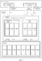
- FIG. 1 is a schematic diagram of a network architecture for querying service data according to an embodiment of the present invention.
- the network architecture for querying service data may include a service system and a BI database system, where the service system may include an analytical service system and a transactional service system, the analytical service system is also referred to as an online analytical processing (OLAP) system in the art, and the transactional service system is also referred to as an online transaction processing (OLTP) in the art.
- the database system may include a database, and a column buffer and a row buffer that are pre-created for the database and that are located in a database memory.
- the database may include a BI database (also referred to as a BI data warehouse in the art) storing data in a column manner or another database, for example, a VFP, a dBASE, an oracle, and an SQL storing data in a column manner. This is not limited in this embodiment of the present invention.
- the analytical service system is mainly used to query data of an analytical service, and the data query of an analytical service generally needs to meet a requirement of quick query, and requires data to be stored in a column manner.
- the transactional service system is mainly used to query data of a transactional service, and the data query of a transactional service generally needs to meet a query requirement of an excessively high throughput, and requires data to be stored in a row manner.
- the data query of an analytical service generally refers to query operations such as filtering and segment statistics collection performed on data based on a condition defined by a user, to help the user to study a pattern of the data, so that a user behavior feature may be explored, providing a basis for specifying a market strategy and a marketing principle.
- the data query of a transactional service refers to that when an event of a user happens (for example, arriving at a predefined region, dialing a predefined number, or visiting a web page that meets a predefined rule), a suitable response feature may be provided.
- column data such as a column 1 to a column 8
- the column buffer may store column data (for example, the column 1, the column 3, and the column 5) by using a column storage architecture, and is mainly applicable to a fast query.
- the row buffer stores column data (for example, the column 3, the column 6, and the column 8) by using a row storage architecture, and is mainly applicable to a query of an excessively high throughput.
- a process of operations for querying service data may include the following steps:
- step 1) to step 6) data of a transactional service can be queried in a database that stores data in a column manner.
- step 2) to step 6) data of a transactional service can be queried in a database that stores data in a column manner.
- it is unnecessary to create two sets of databases for an analytical service and a transactional service and maintenance of data synchronization between the two sets of databases can be omitted when the two sets of databases are used, reducing difficulty in maintenance of a database.
- database system complexity can also be effectively reduced in a manner of not using two sets of databases.
- the row buffer in the row buffer of the database memory, the row buffer may be formatted into several rows, and lengths of the rows are the same (the length is expressed in bytes). In this case, no column data is stored in the row buffer.
- a structure of the row buffer may be shown in Table 1 below: Table 1 Column 1 Column 2 Column 3 Column 4 Column 5 Column 1 Column 2 Column 3 Column 4 Column 5 Column 1 Column 2 Column 3 Column 4 Column 5 Column 1 Column 2 Column 3 Column 4 Column 5
- the database system may divide data of the column 1 according to a quantity of rows (that is, three rows) in the row buffer, to obtain each partial data, which has a fixed length, of the column 1, and load one by one each partial data of the column 1 that is obtained by means of division to a same location of each row of the row buffer (that is, implementing column-to-row conversion of the data of the column 1).
- the database system may divide data of the column 2 according to the quantity of the rows (that is, three rows) in the row buffer, to obtain each partial data, which has a fixed length, of the column 2, and load one by one each partial data of the column 2 that is obtained by means of division to a same location of each row in the row buffer (that is, implementing column-to-row conversion of the data of the column 2)....
- the database system may divide data of the column 5 according to the quantity of the rows (that is, three rows) in the row buffer, to obtain each partial data, which has a fixed length, of the column 5, and load one by one each partial data of the column 5 that is obtained by means of division to a same location of each row in the row buffer (that is, implementing column-to-row conversion of data of the column 5).
- each partial data of the column 1 into which the data of the column 1 is divided has a same length, and each partial data of the column 1 into which the data of the column 1 is divided is in the same location in each row of the row buffer.
- Each partial data of the column 2 into which the data of the column 2 is divided has a same length, and each partial data of the column 2 into which the data of the column 2 is divided is in the same location in each row of row buffer.
- the length of each partial data of the column 1 and the length of each partial data of the column 2 may be different, that is, lengths into which different column data is divided may be different, but lengths or storage locations of a same piece of column data are the same in different rows.
- partial column data in the row buffer may be removed from the row buffer by the database system because the partial column data are not used for a long time and the like, and new column data may continue to be loaded to the row buffer by the database system.
- the structure of the row buffer may be shown in Table 2 below: Table 2 Column 1 Column 3 Column 4 Column 5 Column 6 Column 7 Column 8 Column 1 Column 3 Column 4 Column 5 Column 6 Column 7 Column 8 Column 1 Column 3 Column 4 Column 5 Column 6 Column 7 Column 7 Column 8 Column 1 Column 3 Column 4 Column 5 Column 6 Column 7 Column 8
- the database system may remove the data of the column 2 from the row buffer, and data of the column 6 to data of the column 8 are used as new column data and may be loaded to the row buffer by the database system.
- locations of rows that are occupied by partial column data removed from the row buffer by the database system may be reused, to load new column data.
- Table 3 Column 1 Column 9 Column 3 Column 4 Column 5 Column 6 Column 7 Column 8 Column 1 Column 9 Column 3 Column 4 Column 5 Column 6 Column 7 Column 8 Column 1 Column 9 Column 3 Column 4 Column 5 Column 6 Column 7 Column 8 Column 1 Column 9 Column 3 Column 4 Column 5 Column 6 Column 7 Column 8 Column 5 Column 6 Column 7 Column 8 Column 5 Column 6 Column 7 Column 7 Column 8 Column 1 Column 9 Column 3 Column 4 Column 5 Column 6 Column 7 Column 8
- the database system may create several sub-buffers for the row buffer, where each sub-buffer includes several rows having a same length, the sub-buffers have a same quantity of rows, and rows of a same rank in the several sub-buffers share a same row index, that is, the rows of a same rank in the several sub-buffers belong to a same row.
- Table 4 and Table 5 are two sub-buffers created by the database system for the row buffer, where both of the sub-buffers shown in Table 4 and Table 5 include three rows, a first row in the sub-buffer in Table 4 and a first row in the sub-buffer in Table 5 belong to a same row, a second row in the sub-buffer in Table 4 and a second row in the sub-buffer in Table 5 belong to a same row, and a third row in the sub-buffer in Table 4 and a third row in the sub-buffer in Table 5 belong to a same row.
- data of the column 1 is divided into three pieces of partial data, which has a same length, of the column 1, and the three pieces of partial data of the column 1 into which the data of the column 1 is divided are loaded one by one to a same location of each row included in the sub-buffer shown in the Table 4.
- data of the column 12 is divided into three pieces of partial data, which has a same length, of the column 12, and the three pieces of partial data of the column 12 into which the data of the column 12 is divided are loaded one by one to a same location of each row included in the sub-buffer shown in Table 5.
- the database system may execute combination of the sub-buffers and increase the length of the row of the row buffer, as shown in Table 6: Table 6 Column 1 Column 9 Column 3 Column 4 Column 5 Column 6 ... Column n Column 1 Column 9 Column 3 Column 4 Column 5 Column 6 ... Column n Column 1 Column 9 Column 3 Column 4 Column 5 Column 6 ... Column n Column 1 Column 9 Column 3 Column 4 Column 5 Column 6 ... Column n;
- the database system may add a location having a fixed length to a same location of each row in the row buffer to store index information (that is, a starting storage location of each column data) of the column data whose length cannot be fixed, and then store the column data whose length cannot be fixed to the column buffer.
- index information that is, a starting storage location of each column data
- the column data may be positioned quickly from the column buffer according to the index information of the column data.
- data of a transactional service can be queried in a database that stores data in a column manner.
- it is unnecessary to create two sets of databases for an analytical service and a transactional service and maintenance of data synchronization between the two sets of databases can be omitted when the two sets of databases are used, reducing difficulty in maintenance of a database.
- database system complexity can also be effectively reduced in a manner of not using two sets of databases.
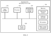
- FIG. 2 is a schematic structural diagram of an apparatus for querying service data according to an embodiment of the present invention.
- the apparatus for querying service data described in FIG. 2 may be configured to perform a function of the database system described above.
- the apparatus for querying service data described in FIG. 2 may be a database system in a physical form.
- description is made by using an example in which a database is a BI database, and when the database is a database of another type, an implementation of this embodiment of the present invention is not affected. As shown in FIG.
- the apparatus for querying service data may include components, such as an input module 201, a processor 202, an output module 203, a memory 204, and a BI database memory module 205. These components may communicate by using one or more communications buses.
- a structure of the apparatus for querying service data shown in FIG. 2 sets no limitation on the present invention, and the structure may be a bus-shaped structure, or may be a star-shaped structure, or may include more or fewer components than those described in FIG. 2 , or some components may be combined, or different component arrangements may be used.
- the input module 201 may be a wired or wireless receiver, and is configured to receive a service data query request sent by a service system (for example, an analytical service system and a transactional service system), and output the request to the processor 202.
- the output module 203 may be a wired or wireless transmitter, and is configured to send the service data found by the processor 202 to the service system.
- the memory 204 may be a high-speed RAM memory, or a non-volatile memory (non-volatile memory), for example, at least one magnetic disk storage.
- the memory 204 may further be at least one storage apparatus that is located far away from the processor 202.
- the memory 204 as a computer physical storage medium may include an operating system, a software program, a BI database, and other storage information. This is not limited in this embodiment of the present invention.
- the BI database memory module 205 is used as a buffer located between a BI database and an external interface, and may be configured to create a column buffer and a row buffer, where the column buffer stores column data by using a column storage architecture, and is mainly applicable to a fast query; and the row buffer stores column data by using a row storage architecture, and is mainly applicable to a query of an excessively high throughput.
- the processor 202 may be configured to invoke the software program stored in the memory 204 to execute the following operations:
- the processor 202 may further invoke the software program stored in the memory 204, to execute the following operations:
- the processor 202 may further invoke the software program stored in the memory 204, to execute the following operations:
- the processor 202 may further invoke the software program stored in the memory 204, to execute the following operations:
- the row buffer may include several sub-buffers, each sub-buffer includes several rows having a same length, the sub-buffers have a same quantity of rows, and rows of a same rank in the several sub-buffers share a same row index, that is, the rows of a same rank in the several sub-buffers belong to a same row; and correspondingly, a manner in which the processor 202 loads the read column data corresponding to the target column identifier to the buffer row in the row buffer may be specifically:
- a manner in which the processor 202 queries, based on the first query condition, the column data that corresponds to the target column identifier, and that is in the row that is in the row buffer of the BI database memory and corresponds to the row index, to obtain the query result is specifically:
- data of a transactional service can be queried in a BI database that stores data in a column manner.
- BI database system complexity can also be effectively reduced in a manner of not using two sets of BI databases.
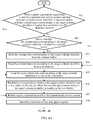
- FIG. 3 is a schematic flowchart of a method for querying service data according to an embodiment of the present invention.
- description is made by using an example in which a database is a BI database, and when the database is a database of another type, an implementation of this embodiment of the present invention is not affected.
- the method for querying service data may include the following steps:
- the BI database system may use different ports to receive the analytical service data query request sent by the analytical service system and the transactional service data query request sent by the transactional service system. Further, the BI database system may identify, according to a port by using which a service data query request is received, whether the service data query request is the analytical service data query request that is sent by the analytical service system and that includes the specified column identifier and the second query condition, or is the transactional service data query request that is sent by the transactional service system and that includes the target column identifier and the first query condition.
- the analytical service data query request sent by the analytical service system and the transactional service data query request sent by the transactional service system may separately carry different service type identifiers.
- the BI database system may identify, according to a service type identifier carried by a received service data query request, whether the service data query request is the analytical service data query request that is sent by the analytical service system and that includes the specified column identifier and the second query condition, or is the transactional service data query request that is sent by the transactional service system and that includes the target column identifier and the first query condition.
- the specified column identifier and the target column identifier may also be referred to as customer identifiers because all data of each customer may be used as column data for storage in the BI database.
- the first query condition and the second query condition are mainly used to perform querying operations such as filtering and statistics collection on the column data.
- the BI database system detects whether column data corresponding to the specified column identifier is loaded in a column buffer of a BI database memory, and if not, step 303 is performed, or if yes, step 304 and step 305 are performed.
- the BI database system reads the column data corresponding to the specified column identifier from a BI database, and loads the read column data corresponding to the specified column identifier to a column of the column buffer, and step 304 and step 305 are performed.
- the BI database system may load in advance the column data corresponding to the specified column identifier from the BI database to a column of the column buffer.
- the BI database system queries, based on the second query condition, the column data corresponding to the specified column identifier from the column buffer, to obtain a query result.
- Table 6 and Table 7 are created below in the BI database.
- Table 6 (A name of the table is t1) Field name (that is, column identifier) Type attr0 User Id attr1 Amount attr2 Amount attr3 Amount attr4 Amount attr5 Integer attr6 Integer attr7 Integer ... ...
- Table 7 (A name of the table is t2) Field name (that is, column identifier) Type attr0 User Id f1 Amount f2 Amount f3 Amount f4 Short f5 Integer f6 Integer f7 Integer f8 Dict ... ...
- Table 6 and Table 7 may be stored in a file form, as shown in Table 8: Table 8 Field name (that is, column identifier) File type t1.attr0 Column data file t1.attr1 Column data file t1.attr2 Column data file t1.attr3 Column data file t1.attr4 Column data file t1.attr5 Column data file t1.attr6 Column data file t1.attr7 Column data file ... ... t2.attr0 Column data file t2.f1 Column data file t2.f2 Column data file t2.f3 Column data file t2.f4 Column data file t2.f5 Column data file ... ... ...
- the analytical service data query request that is received by the BI database system and that is sent by the analytical service system may include the following second query condition, that is:
- the BI database system may detect whether column data corresponding to t1.attr1, t1.attr0, t2.attr0, and t2.f1 is loaded in the column buffer of the BI database memory, and if yes, queries the column data corresponding to t1.attr1, t1.attr0, t2.attr0, and t2.f1 from the column buffer based on the second query condition, to obtain a query result, or if not, the BI database system reads the column data corresponding to t1.attr1, t1.attr0, t2.attr0, and t2.f1 from the BI database, loads the read column data to a column of the column buffer, and queries, based on the second query condition, the column data corresponding to t1.attr1, t1.attr0, t2.attr0, and t2.f1 from the column buffer, to obtain a query result.
- the query result may include various service data, such as a traffic value, a sales value, a sales target, and transaction data.
- the BI database system returns the query result to the analytical service system, and ends the process.
- step 306 The BI database system detects whether a row index corresponding to the target column identifier exists, and if it is detected that the row index corresponding to the target column identifier does not exist, step 307 is performed, or if it is detected that the row index corresponding to the target column identifier exists, step 312 and step 313 are performed.
- step 307 The BI database system detects whether column data corresponding to the target column identifier is loaded in the column buffer, and if the column data corresponding to the target column identifier is loaded in the column buffer, step 308 is performed, or if the column data corresponding to the target column identifier is not loaded in the column buffer, step 309 is performed.
- the BI database system reads the column data corresponding to the target column identifier from the column buffer, and step 310 is performed.
- the BI database system reads the column data corresponding to the target column identifier from the BI database, and step 310 is performed.
- the BI database system loads the read column data corresponding to the target column identifier to a row in a row buffer.
- the row buffer may include several sub-buffers, each sub-buffer includes several rows having a same length, the sub-buffers have a same quantity of rows, and rows of a same rank in the several sub-buffers share a same row index, that is, the rows of a same rank in the several sub-buffers belong to a same row.
- a manner in which the BI database system loads the read column data corresponding to the target column identifier to the row in the row buffer may be specifically:
- the transactional service data query request that is received by the BI database system and that is sent by the transactional service system may include the following first query condition, that is:
- the BI database system may detect whether a row index corresponding to the target column identifier such as t1.attr0, t1.attr1, t1.attr2, t1.attr3, t1.attr4, t1.attr5, t1.attr6, t2.f6, t2.f7, t2.f8, and t2.f9, exists, and if an row index corresponding to t1.attr0 and t2.f6 exists, it indicates that column data corresponding to t1.attr0 and t2.f6 is already loaded to a row of the row buffer, or if an row index corresponding to t1.attr1, t1.attr2, t1.attr3, t1.attr4, t1.attr5, t1.attr6, t2.f7, t2.f8, and t2.f9 does not exist, it indicates that column data corresponding to t1.attr1, t1.attr2,
- the BI database system may detect whether the column data corresponding to t1.attr1, t1.attr2, t1.attr3, t1.attr4, t1.attr5, t1.attr6, t2.f7, t2.f8, and t2.f9 is loaded in the column buffer, and if the column data corresponding to t1.attr1, t1.attr2, t1.attr3, t1.attr4, t1.attr5, t1.attr6, t2.f7, t2.f8, and t2.f9 is loaded in the column buffer, the BI database system may read the column data corresponding to t1.attr1, t1.attr2, t1.attr3, t1.attr4, t1.attr5, t1.attr6, t2.f7, t2.f8, and t2.f9 from the column buffer, or if the column data corresponding to t1.attr1, t
- the BI database system may load the read column data corresponding to t1.attr1, t1.attr2, t1.attr3, t1.attr4, t1.attr5, t1.attr6, t2.f7, t2.f8, and t2.f9 to a row in the row buffer (that is, column-to-row conversion).
- the BI database system establishes a correspondence between the target column identifier and a row index of the row, to which the column data corresponding to the target column identifier is loaded, in the row buffer, and step 312 is performed.
- the correspondence may be used to indicate that the column data corresponding to the target column identifier is already loaded to the row of the row buffer. In this way, the BI database system may detect, according to the correspondence, that the row index corresponding to the target column identifier exists next time.
- the BI database system queries, based on the first query condition, the column data that corresponds to the target column identifier, and that is in the row that is in the row buffer of the BI database memory and corresponds to the row index, to obtain a query result.
- a manner in which the BI database system queries, based on the first query condition, the column data that corresponds to the target column identifier, and that is in the row that is in the row buffer of the BI database memory and corresponds to the row index, to obtain the query result may be specifically:
- the BI database system may determine each row that corresponds to the row index 13800138000 in the row buffer of the BI database memory and that is located in any one of the sub-buffers, and query, based on the first query condition, each partial column data that corresponds to t1.attr0, t1.attr1, t1.attr2, t1.attr3, t1.attr4, t1.attr5, t1.attr6, t2.f6, t2.f7, t2.f8, and t2.f9, and that is located
- the BI database system returns the query result to the transactional service system, and the process ends.
- data of a transactional service can be queried in a BI database that stores data in a column manner.
- BI database system complexity can also be effectively reduced in a manner of not using two sets of BI databases.
- FIG. 4A and FIG. 4B are schematic flowcharts of another method for querying service data according to an embodiment of the present invention.
- description is made by using an example in which a database is a BI database, and when the database is a database of another type, an implementation of this embodiment of the present invention is not affected.
- the method for querying service data described in FIG. 4A and FIG. 4B is described in FIG. 4A and FIG.
- the BI database system may receive in advance a query registration request sent by a transactional service system, and in response to the query registration request, the BI database system loads in advance column data that is not loaded to a row buffer of a BI database memory to the row buffer, so that the transactional service system subsequently queries data of a transactional service.
- the method for querying service data may include the following steps:
- the query registration request that is sent by transactional service system, that includes the target column identifier, and that is received by the BI database system may be:
- the BI database system detects whether the column data corresponding to the target column identifier is loaded in a column buffer, and if the column data corresponding to the target column identifier is loaded in the column buffer, step 403 is performed, or if the column data corresponding to the target column identifier is not loaded in the column buffer, step 404 is performed.
- the BI database system reads the column data corresponding to the target column identifier from the column buffer, and step 405 is performed.
- the BI database system reads the column data corresponding to the target column identifier from a BI database, and step 405 is performed.
- the BI database system loads the read column data corresponding to the target column identifier to a row in the row buffer.
- the row buffer may include several sub-buffers, each sub-buffer includes several rows having a same length, the sub-buffers have a same quantity of rows, and rows of a same rank in the several sub-buffers share a same row index, that is, the rows of a same rank in the several sub-buffers belong to a same row.
- step 405 a manner in which the BI database system loads the column data corresponding to the target column identifier to the row in the row buffer may be specifically:
- the BI database system establishes a correspondence between the target column identifier and a row index of the row.
- the BI database system returns a query registration result to the transactional service system.
- the query registration result may also be referred to as metadata, and is mainly used to indicate that the column data corresponding to the target column identifier is already loaded in the row buffer.
- the BI database system identifies a received service data query request, and when the service data query request is an analytical service data query request that is sent by an analytical service system and that includes a specified column identifier and a second query condition, step 409 is performed, or when the service data query request is a transactional service data query request that is sent by a transactional service system and that includes a target column identifier and a first query condition, step 413 is performed.
- step 409 The BI database system detects whether column data corresponding to the specified column identifier is loaded in the column buffer of the BI database memory, and if not, step 410 is performed, or if yes, step 411 to step 412 are performed.
- the BI database system reads the column data corresponding to the specified column identifier from the BI database, and loads the read column data corresponding to the specified column identifier to a column of the column buffer, and step 411 to step 412 are performed.
- the BI database system queries, based on the second query condition, the column data corresponding to the specified column identifier from the column buffer, to obtain a query result.
- the BI database system returns the query result to the analytical service system.
- the BI database system detects whether a row index corresponding to the target column identifier exists, and if it is detected that the row index corresponding to the target column identifier does not exist, the processing ends, or if it is detected that the row index corresponding to the target column identifier exists, step 414 and step 415 are performed.
- the BI database system may detect, according to the correspondence established in step 406, whether the row index corresponding to the target column identifier exists.
- the BI database system queries, based on the first query condition, the column data corresponding to the target column identifier in the row corresponding to the row index in the row buffer of the BI database memory, to obtain a query result.
- step 414 a manner in which the BI database system queries, based on the first query condition, the column data corresponding to the target column identifier in the row corresponding to the row index in the row buffer of the BI database memory, to obtain the query result may be specifically:
- the BI database system returns the query result to the transactional service system.
- data of a transactional service can be queried in a BI database that stores data in a column manner.
- BI database system complexity can also be effectively reduced in a manner of not using two sets of BI databases.
- FIG. 5 is a schematic structural diagram of an apparatus for querying service data according to an embodiment of the present invention.
- the apparatus for querying service data shown in FIG. 5 may be configured to perform a function of the database system described above.
- the database memory includes a column buffer and a row buffer, a column of the column buffer is used to load column data of a database, and a row of the row buffer is used to load column data of the column buffer or the column data of the database.
- the database may include a BI database (also referred to as a BI data warehouse in the art) storing data in a column manner or another database, for example, a VFP, a dBASE, an oracle, and an SQL storing data in a column manner.
- a BI database also referred to as a BI data warehouse in the art
- the apparatus for querying service data may include:
- FIG. 6 is a schematic structural diagram of another apparatus for querying service data according to an embodiment of the present invention.
- the apparatus for querying service data shown in FIG. 6 is obtained by optimizing the apparatus for querying service data shown in FIG. 5 .
- the apparatus for querying service data shown in the FIG. 6 may further include:
- the row buffer may include several sub-buffers, each sub-buffer includes several rows having a same length, the sub-buffers have a same quantity of rows, and rows of a same rank in the several sub-buffers share a same row index, that is, the rows of a same rank in the several sub-buffers belong to a same row.
- a manner in which the first loading unit 506 loads the read column data corresponding to the target column identifier to the row in the row buffer may be specifically: dividing, by the first loading unit 506, according to the quantity of the rows of the sub-buffer in the row buffer, the read column data corresponding to the target column identifier, and loading one by one each partial column data obtained by means of division to a same location of each row included in any one of the sub-buffers.
- the first query unit 502 includes:
- FIG. 7 is a schematic structural diagram of another apparatus for querying service data according to an embodiment of the present invention.
- the apparatus for querying service data shown in FIG. 7 is obtained by optimizing the apparatus for querying service data shown in FIG. 5 .
- the apparatus for querying service data shown in FIG. 7 is compared with the apparatus for querying service data shown in FIG. 5 .
- the 7 may further include a third detection unit 508, a second reading unit 509, a second loading unit 510, and a second establishing unit 511, where the first detection unit 501 is further configured to: before receiving the transactional service data query request that is sent by the transactional service system and that includes the target column identifier and the first query condition, when receiving a query registration request that is sent by the transactional service system and that includes the target column identifier, detect whether the column data corresponding to the target column identifier is loaded in the row buffer; the third detection unit 508 is configured to: when the first detection unit 501 detects that the column data corresponding to the target column identifier is not loaded in the row buffer, detect whether the column data corresponding to the target column identifier is loaded in the column buffer; the second reading unit 509 is configured to: when the third detection unit 508 detects that the column data corresponding to the target column identifier is loaded in the column buffer, read the column data corresponding to the target column identifier from the column buffer; and further configured to: when
- the first detection unit 501 may detect whether the row index corresponding to the target column identifier exists in the correspondence established by the second establishing unit 511.
- the row buffer may include several sub-buffers, each sub-buffer includes several rows having a same length, the sub-buffers have a same quantity of rows, and rows of a same rank in the several sub-buffers share a same row index, that is, the rows of a same rank in the several sub-buffers belong to a same row.
- a manner in which the second loading unit 510 loads the read column data corresponding to the target column identifier to the row in the row buffer is specifically: dividing, by the second loading unit 510 according to the quantity of the rows of the sub-buffer in the row buffer, the read column data corresponding to the target column identifier, and loading one by one each partial column data obtained by means of division to a same location of each row included in any one of the sub-buffers.
- a first query unit 502 includes:
- data of a transactional service can be queried in a database that stores data in a column manner.
- it is unnecessary to create two sets of databases for an analytical service and a transactional service and maintenance of data synchronization between the two sets of databases can be omitted when the two sets of databases are used, reducing difficulty in maintenance of a database.
- database system complexity can also be effectively reduced in a manner of not using two sets of databases.
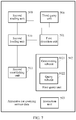
- FIG. 8 is a schematic structural diagram of a database system according to an embodiment of the present invention.
- the database system may include components, such as an apparatus for querying service data 801, a database memory 802, and a database 803.
- the components, such as the apparatus for querying service data 801, the BI database memory 802, and the database803, may be connected by using a bus.
- a structure and a function of the apparatus for querying service data 801 may be the same as a structure and a function of any apparatus for querying service data in FIG. 5 to FIG. 7 , and details are not described herein again in this embodiment of the present invention.
- the database memory 802 may include a column buffer and a row buffer, a column of the column buffer is used to load column data of the database 803, and a row of the row buffer is used to load column data of the column buffer or the column data of the database 803.
- the database 803 may include a BI database (also referred to as a BI data warehouse in the art) storing data in a column manner or another database, for example, a VFP, a dBASE, an oracle, and an SQL storing data in a column manner. This is not limited in this embodiment of the present invention.
- data of a transactional service can be queried in a database that stores data in a column manner.
- it is unnecessary to create two sets of databases for an analytical service and a transactional service and maintenance of data synchronization between the two sets of databases can be omitted when the two sets of databases are used, reducing difficulty in maintenance of a database.
- database system complexity can also be effectively reduced in a manner of not using two sets of databases.
- event triggering can be only performed less frequently.
- a quantity of queried CAPS does not exceed ten thousand A query may be performed not only for an analytical service but also for a transactional service. In an actual application, a quantity of CAPS exceeds one million
- a sequence of the steps of the method in the embodiments of the present invention may be adjusted, and certain steps may also be merged and removed according to an actual requirement.
- the units or subunits in the terminal or device in the embodiments of the present invention may be adjusted, divided, and removed according to an actual requirement.
- the program may be stored in a computer readable storage medium.
- the storage medium includes a read-only memory (Read-Only Memory, ROM), a random access memory (Random Access Memory, RAM), a programmable read-only memory (Programmable Read-only Memory, PROM), an erasable programmable read-only memory (Erasable Programmable Read Only Memory, EPROM), a one-time programmable read-only memory (One-time Programmable Read-Only Memory, OTPROM), an electrically-erasable programmable read-only memory, (Electrically-Erasable Programmable Read-Only Memory, EEPROM), a compact disc read-only memory (Compact Disc Read-Only Memory, CD-ROM), or another optical disk memory, magnetic disk memory, magnetic tape memory, or any other computer readable medium that can be configured to carry or store data
Landscapes
- Engineering & Computer Science (AREA)
- Theoretical Computer Science (AREA)
- Databases & Information Systems (AREA)
- Data Mining & Analysis (AREA)
- Physics & Mathematics (AREA)
- General Engineering & Computer Science (AREA)
- General Physics & Mathematics (AREA)
- Computational Linguistics (AREA)
- Software Systems (AREA)
- Information Retrieval, Db Structures And Fs Structures Therefor (AREA)
Applications Claiming Priority (2)
| Application Number | Priority Date | Filing Date | Title |
|---|---|---|---|
| CN201410804281.6A CN104537030B (zh) | 2014-12-22 | 2014-12-22 | 一种业务数据查询方法及装置、数据库系统 |
| PCT/CN2015/089802 WO2016101659A1 (zh) | 2014-12-22 | 2015-09-16 | 一种业务数据查询方法及装置、数据库系统 |
Publications (3)
| Publication Number | Publication Date |
|---|---|
| EP3226152A1 true EP3226152A1 (de) | 2017-10-04 |
| EP3226152A4 EP3226152A4 (de) | 2017-11-22 |
| EP3226152B1 EP3226152B1 (de) | 2020-07-15 |
Family
ID=52852558
Family Applications (1)
| Application Number | Title | Priority Date | Filing Date |
|---|---|---|---|
| EP15871733.0A Active EP3226152B1 (de) | 2014-12-22 | 2015-09-16 | Verfahren und vorrichtung zur abfrage von servicedaten und datenbanksystem |
Country Status (4)
| Country | Link |
|---|---|
| US (1) | US20170286470A1 (de) |
| EP (1) | EP3226152B1 (de) |
| CN (1) | CN104537030B (de) |
| WO (1) | WO2016101659A1 (de) |
Families Citing this family (14)
| Publication number | Priority date | Publication date | Assignee | Title |
|---|---|---|---|---|
| CN104537030B (zh) * | 2014-12-22 | 2018-03-02 | 华为技术有限公司 | 一种业务数据查询方法及装置、数据库系统 |
| CN107220186A (zh) * | 2017-07-03 | 2017-09-29 | 福建新和兴信息技术有限公司 | Android系统中业务对象的缓存管理方法及终端 |
| EP3665544A4 (de) * | 2017-09-14 | 2021-05-05 | Savizar, Inc. | Datenbankmotor |
| CN109634951B (zh) * | 2018-10-23 | 2023-12-22 | 平安科技(深圳)有限公司 | 大数据采集方法、装置、计算机设备及存储介质 |
| CN109656930A (zh) * | 2018-12-27 | 2019-04-19 | 广州华多网络科技有限公司 | 数据查询方法、装置及系统 |
| CN109800237A (zh) * | 2019-01-28 | 2019-05-24 | 广州酷狗计算机科技有限公司 | 数据查询方法、装置和计算机可读存储介质 |
| CN110502551A (zh) * | 2019-08-02 | 2019-11-26 | 阿里巴巴集团控股有限公司 | 数据读写方法、系统及架构组件 |
| CN110866006A (zh) * | 2019-10-12 | 2020-03-06 | 苏宁云计算有限公司 | 过期数据的归档方法和装置 |
| CN113254480B (zh) * | 2020-02-13 | 2024-04-19 | 中国移动通信集团广东有限公司 | 一种数据查询方法及装置 |
| CN113626449A (zh) * | 2021-07-02 | 2021-11-09 | 上海硬通网络科技有限公司 | 数据存储、数据查询方法及相关设备 |
| CN115712616B (zh) * | 2022-11-29 | 2026-03-03 | 瀚高基础软件股份有限公司 | 一种基于学习型索引的索引方法及装置、电子设备 |
| CN117349288A (zh) * | 2023-10-24 | 2024-01-05 | 北京火山引擎科技有限公司 | 基于联机分析处理的数据查询方法、装置和电子设备 |
| CN117633035A (zh) * | 2023-11-22 | 2024-03-01 | 北京奥星贝斯科技有限公司 | 数据查询方法及装置 |
| CN118964353A (zh) * | 2024-07-29 | 2024-11-15 | 哈尔滨工业大学 | 一种面向事务型和分析型的混合查询负载的图存储方法 |
Family Cites Families (14)
| Publication number | Priority date | Publication date | Assignee | Title |
|---|---|---|---|---|
| US10152504B2 (en) * | 2009-03-11 | 2018-12-11 | Actian Netherlands B.V. | Column-store database architecture utilizing positional delta tree update system and methods |
| CN101840430B (zh) * | 2010-04-28 | 2012-02-29 | 北京握奇数据系统有限公司 | 智能卡数据库多表操作方法及装置 |
| US8782100B2 (en) * | 2011-12-22 | 2014-07-15 | Sap Ag | Hybrid database table stored as both row and column store |
| CN102495905A (zh) * | 2011-12-23 | 2012-06-13 | 天津神舟通用数据技术有限公司 | 一种基于行存数据库引擎的列存方法 |
| CN102609492B (zh) * | 2012-01-21 | 2014-05-28 | 东华大学 | 一种支持表模式可变的元数据管理方法 |
| CN103870497B (zh) * | 2012-12-14 | 2019-03-12 | Sap欧洲公司 | 用于基于列的数据库的列智能机制 |
| US10108668B2 (en) * | 2012-12-14 | 2018-10-23 | Sap Se | Column smart mechanism for column based database |
| US10296462B2 (en) * | 2013-03-15 | 2019-05-21 | Oracle International Corporation | Method to accelerate queries using dynamically generated alternate data formats in flash cache |
| CN103218415A (zh) * | 2013-03-27 | 2013-07-24 | 互爱互动(北京)科技有限公司 | 基于数据仓库的数据处理系统和方法 |
| CN103226610B (zh) * | 2013-05-07 | 2016-06-29 | 华为技术有限公司 | 数据库表查询方法和装置 |
| CN103942342B (zh) * | 2014-05-12 | 2017-02-01 | 中国人民大学 | 一种内存数据库oltp&olap并发查询优化方法 |
| CN103970870A (zh) * | 2014-05-12 | 2014-08-06 | 华为技术有限公司 | 数据库查询方法和服务器 |
| CN104090987B (zh) * | 2014-07-28 | 2018-03-13 | 华中科技大学 | 一种历史数据存储及索引方法 |
| CN104537030B (zh) * | 2014-12-22 | 2018-03-02 | 华为技术有限公司 | 一种业务数据查询方法及装置、数据库系统 |
-
2014
- 2014-12-22 CN CN201410804281.6A patent/CN104537030B/zh active Active
-
2015
- 2015-09-16 WO PCT/CN2015/089802 patent/WO2016101659A1/zh not_active Ceased
- 2015-09-16 EP EP15871733.0A patent/EP3226152B1/de active Active
-
2017
- 2017-06-22 US US15/630,195 patent/US20170286470A1/en not_active Abandoned
Also Published As
| Publication number | Publication date |
|---|---|
| WO2016101659A1 (zh) | 2016-06-30 |
| CN104537030B (zh) | 2018-03-02 |
| EP3226152B1 (de) | 2020-07-15 |
| EP3226152A4 (de) | 2017-11-22 |
| US20170286470A1 (en) | 2017-10-05 |
| CN104537030A (zh) | 2015-04-22 |
Similar Documents
| Publication | Publication Date | Title |
|---|---|---|
| EP3226152B1 (de) | Verfahren und vorrichtung zur abfrage von servicedaten und datenbanksystem | |
| US10331642B2 (en) | Data storage method and apparatus | |
| US11650990B2 (en) | Method, medium, and system for joining data tables | |
| US20160267099A1 (en) | Similarity Analysis Method, Apparatus, and System | |
| US20160328445A1 (en) | Data Query Method and Apparatus | |
| US11030196B2 (en) | Method and apparatus for processing join query | |
| US20260105052A1 (en) | Data query method and related device | |
| EP3376403A1 (de) | Verfahren für zugriff auf verteilte datenbank und vorrichtung zur bereitstellung eines verteilten datendienstes | |
| US11372822B2 (en) | Method, device, and computer apparatus for merging regions of HBase table | |
| US20180276262A1 (en) | Data Storage Method and Apparatus | |
| US20150193491A1 (en) | Data indexing method and apparatus | |
| JP2013536492A (ja) | 複数のシステムを用いたデータ解析 | |
| US20160179836A1 (en) | Method for updating data table of keyvalue database and apparatus for updating table data | |
| US9760604B2 (en) | System and method for adaptive filtering of data requests | |
| US20160132542A1 (en) | Online index rebuilding method and apparatus | |
| KR101640733B1 (ko) | 인-메모리 데이터베이스 기반의 데이터 관리 시스템 및 그 방법 | |
| US20190108174A1 (en) | Data Table Processing Method and Apparatus | |
| EP3401862A1 (de) | Datenspeicherung und dienstverarbeitungsverfahren und vorrichtung | |
| CN111159131A (zh) | 性能优化方法、装置、设备及计算机可读存储介质 | |
| CN106682047B (zh) | 一种数据导入方法以及相关装置 | |
| US10970478B2 (en) | Tabular data analysis method, recording medium storing tabular data analysis program, and information processing apparatus | |
| CN114428789A (zh) | 数据的处理方法及装置 | |
| CN114756626A (zh) | 数据处理方法、装置、设备以及存储介质 | |
| CN110019084B (zh) | 面向HDFS的split层索引方法和装置 | |
| CN115934727A (zh) | 信息查询方法、装置及计算机可读取存储介质 |
Legal Events
| Date | Code | Title | Description |
|---|---|---|---|
| STAA | Information on the status of an ep patent application or granted ep patent |
Free format text: STATUS: THE INTERNATIONAL PUBLICATION HAS BEEN MADE |
|
| PUAI | Public reference made under article 153(3) epc to a published international application that has entered the european phase |
Free format text: ORIGINAL CODE: 0009012 |
|
| STAA | Information on the status of an ep patent application or granted ep patent |
Free format text: STATUS: REQUEST FOR EXAMINATION WAS MADE |
|
| 17P | Request for examination filed |
Effective date: 20170627 |
|
| AK | Designated contracting states |
Kind code of ref document: A1 Designated state(s): AL AT BE BG CH CY CZ DE DK EE ES FI FR GB GR HR HU IE IS IT LI LT LU LV MC MK MT NL NO PL PT RO RS SE SI SK SM TR |
|
| AX | Request for extension of the european patent |
Extension state: BA ME |
|
| A4 | Supplementary search report drawn up and despatched |
Effective date: 20171020 |
|
| RIC1 | Information provided on ipc code assigned before grant |
Ipc: G06F 17/30 20060101AFI20171016BHEP |
|
| DAV | Request for validation of the european patent (deleted) | ||
| DAX | Request for extension of the european patent (deleted) | ||
| STAA | Information on the status of an ep patent application or granted ep patent |
Free format text: STATUS: EXAMINATION IS IN PROGRESS |
|
| 17Q | First examination report despatched |
Effective date: 20181019 |
|
| REG | Reference to a national code |
Ref country code: DE Ref legal event code: R079 Ref document number: 602015055960 Country of ref document: DE Free format text: PREVIOUS MAIN CLASS: G06F0017300000 Ipc: G06F0016220000 |
|
| GRAP | Despatch of communication of intention to grant a patent |
Free format text: ORIGINAL CODE: EPIDOSNIGR1 |
|
| STAA | Information on the status of an ep patent application or granted ep patent |
Free format text: STATUS: GRANT OF PATENT IS INTENDED |
|
| RIC1 | Information provided on ipc code assigned before grant |
Ipc: G06F 16/2455 20190101ALI20200115BHEP Ipc: G06F 16/22 20190101AFI20200115BHEP |
|
| INTG | Intention to grant announced |
Effective date: 20200211 |
|
| GRAS | Grant fee paid |
Free format text: ORIGINAL CODE: EPIDOSNIGR3 |
|
| GRAA | (expected) grant |
Free format text: ORIGINAL CODE: 0009210 |
|
| STAA | Information on the status of an ep patent application or granted ep patent |
Free format text: STATUS: THE PATENT HAS BEEN GRANTED |
|
| AK | Designated contracting states |
Kind code of ref document: B1 Designated state(s): AL AT BE BG CH CY CZ DE DK EE ES FI FR GB GR HR HU IE IS IT LI LT LU LV MC MK MT NL NO PL PT RO RS SE SI SK SM TR |
|
| REG | Reference to a national code |
Ref country code: CH Ref legal event code: EP Ref country code: GB Ref legal event code: FG4D |
|
| REG | Reference to a national code |
Ref country code: IE Ref legal event code: FG4D |
|
| REG | Reference to a national code |
Ref country code: DE Ref legal event code: R096 Ref document number: 602015055960 Country of ref document: DE |
|
| REG | Reference to a national code |
Ref country code: AT Ref legal event code: REF Ref document number: 1291790 Country of ref document: AT Kind code of ref document: T Effective date: 20200815 |
|
| REG | Reference to a national code |
Ref country code: LT Ref legal event code: MG4D |
|
| REG | Reference to a national code |
Ref country code: AT Ref legal event code: MK05 Ref document number: 1291790 Country of ref document: AT Kind code of ref document: T Effective date: 20200715 |
|
| REG | Reference to a national code |
Ref country code: NL Ref legal event code: MP Effective date: 20200715 |
|
| PG25 | Lapsed in a contracting state [announced via postgrant information from national office to epo] |
Ref country code: PT Free format text: LAPSE BECAUSE OF FAILURE TO SUBMIT A TRANSLATION OF THE DESCRIPTION OR TO PAY THE FEE WITHIN THE PRESCRIBED TIME-LIMIT Effective date: 20201116 Ref country code: HR Free format text: LAPSE BECAUSE OF FAILURE TO SUBMIT A TRANSLATION OF THE DESCRIPTION OR TO PAY THE FEE WITHIN THE PRESCRIBED TIME-LIMIT Effective date: 20200715 Ref country code: AT Free format text: LAPSE BECAUSE OF FAILURE TO SUBMIT A TRANSLATION OF THE DESCRIPTION OR TO PAY THE FEE WITHIN THE PRESCRIBED TIME-LIMIT Effective date: 20200715 Ref country code: LT Free format text: LAPSE BECAUSE OF FAILURE TO SUBMIT A TRANSLATION OF THE DESCRIPTION OR TO PAY THE FEE WITHIN THE PRESCRIBED TIME-LIMIT Effective date: 20200715 Ref country code: SE Free format text: LAPSE BECAUSE OF FAILURE TO SUBMIT A TRANSLATION OF THE DESCRIPTION OR TO PAY THE FEE WITHIN THE PRESCRIBED TIME-LIMIT Effective date: 20200715 Ref country code: BG Free format text: LAPSE BECAUSE OF FAILURE TO SUBMIT A TRANSLATION OF THE DESCRIPTION OR TO PAY THE FEE WITHIN THE PRESCRIBED TIME-LIMIT Effective date: 20201015 Ref country code: FI Free format text: LAPSE BECAUSE OF FAILURE TO SUBMIT A TRANSLATION OF THE DESCRIPTION OR TO PAY THE FEE WITHIN THE PRESCRIBED TIME-LIMIT Effective date: 20200715 Ref country code: GR Free format text: LAPSE BECAUSE OF FAILURE TO SUBMIT A TRANSLATION OF THE DESCRIPTION OR TO PAY THE FEE WITHIN THE PRESCRIBED TIME-LIMIT Effective date: 20201016 Ref country code: NO Free format text: LAPSE BECAUSE OF FAILURE TO SUBMIT A TRANSLATION OF THE DESCRIPTION OR TO PAY THE FEE WITHIN THE PRESCRIBED TIME-LIMIT Effective date: 20201015 Ref country code: ES Free format text: LAPSE BECAUSE OF FAILURE TO SUBMIT A TRANSLATION OF THE DESCRIPTION OR TO PAY THE FEE WITHIN THE PRESCRIBED TIME-LIMIT Effective date: 20200715 |
|
| PG25 | Lapsed in a contracting state [announced via postgrant information from national office to epo] |
Ref country code: LV Free format text: LAPSE BECAUSE OF FAILURE TO SUBMIT A TRANSLATION OF THE DESCRIPTION OR TO PAY THE FEE WITHIN THE PRESCRIBED TIME-LIMIT Effective date: 20200715 Ref country code: RS Free format text: LAPSE BECAUSE OF FAILURE TO SUBMIT A TRANSLATION OF THE DESCRIPTION OR TO PAY THE FEE WITHIN THE PRESCRIBED TIME-LIMIT Effective date: 20200715 Ref country code: PL Free format text: LAPSE BECAUSE OF FAILURE TO SUBMIT A TRANSLATION OF THE DESCRIPTION OR TO PAY THE FEE WITHIN THE PRESCRIBED TIME-LIMIT Effective date: 20200715 Ref country code: IS Free format text: LAPSE BECAUSE OF FAILURE TO SUBMIT A TRANSLATION OF THE DESCRIPTION OR TO PAY THE FEE WITHIN THE PRESCRIBED TIME-LIMIT Effective date: 20201115 |
|
| PG25 | Lapsed in a contracting state [announced via postgrant information from national office to epo] |
Ref country code: NL Free format text: LAPSE BECAUSE OF FAILURE TO SUBMIT A TRANSLATION OF THE DESCRIPTION OR TO PAY THE FEE WITHIN THE PRESCRIBED TIME-LIMIT Effective date: 20200715 |
|
| REG | Reference to a national code |
Ref country code: DE Ref legal event code: R097 Ref document number: 602015055960 Country of ref document: DE |
|
| PG25 | Lapsed in a contracting state [announced via postgrant information from national office to epo] |
Ref country code: CZ Free format text: LAPSE BECAUSE OF FAILURE TO SUBMIT A TRANSLATION OF THE DESCRIPTION OR TO PAY THE FEE WITHIN THE PRESCRIBED TIME-LIMIT Effective date: 20200715 Ref country code: DK Free format text: LAPSE BECAUSE OF FAILURE TO SUBMIT A TRANSLATION OF THE DESCRIPTION OR TO PAY THE FEE WITHIN THE PRESCRIBED TIME-LIMIT Effective date: 20200715 Ref country code: IT Free format text: LAPSE BECAUSE OF FAILURE TO SUBMIT A TRANSLATION OF THE DESCRIPTION OR TO PAY THE FEE WITHIN THE PRESCRIBED TIME-LIMIT Effective date: 20200715 Ref country code: EE Free format text: LAPSE BECAUSE OF FAILURE TO SUBMIT A TRANSLATION OF THE DESCRIPTION OR TO PAY THE FEE WITHIN THE PRESCRIBED TIME-LIMIT Effective date: 20200715 Ref country code: SM Free format text: LAPSE BECAUSE OF FAILURE TO SUBMIT A TRANSLATION OF THE DESCRIPTION OR TO PAY THE FEE WITHIN THE PRESCRIBED TIME-LIMIT Effective date: 20200715 Ref country code: RO Free format text: LAPSE BECAUSE OF FAILURE TO SUBMIT A TRANSLATION OF THE DESCRIPTION OR TO PAY THE FEE WITHIN THE PRESCRIBED TIME-LIMIT Effective date: 20200715 |
|
| REG | Reference to a national code |
Ref country code: CH Ref legal event code: PL |
|
| PLBE | No opposition filed within time limit |
Free format text: ORIGINAL CODE: 0009261 |
|
| STAA | Information on the status of an ep patent application or granted ep patent |
Free format text: STATUS: NO OPPOSITION FILED WITHIN TIME LIMIT |
|
| PG25 | Lapsed in a contracting state [announced via postgrant information from national office to epo] |
Ref country code: AL Free format text: LAPSE BECAUSE OF FAILURE TO SUBMIT A TRANSLATION OF THE DESCRIPTION OR TO PAY THE FEE WITHIN THE PRESCRIBED TIME-LIMIT Effective date: 20200715 |
|
| REG | Reference to a national code |
Ref country code: BE Ref legal event code: MM Effective date: 20200930 |
|
| 26N | No opposition filed |
Effective date: 20210416 |
|
| PG25 | Lapsed in a contracting state [announced via postgrant information from national office to epo] |
Ref country code: SK Free format text: LAPSE BECAUSE OF FAILURE TO SUBMIT A TRANSLATION OF THE DESCRIPTION OR TO PAY THE FEE WITHIN THE PRESCRIBED TIME-LIMIT Effective date: 20200715 Ref country code: LU Free format text: LAPSE BECAUSE OF NON-PAYMENT OF DUE FEES Effective date: 20200916 |
|
| PG25 | Lapsed in a contracting state [announced via postgrant information from national office to epo] |
Ref country code: FR Free format text: LAPSE BECAUSE OF NON-PAYMENT OF DUE FEES Effective date: 20200930 |
|
| PG25 | Lapsed in a contracting state [announced via postgrant information from national office to epo] |
Ref country code: CH Free format text: LAPSE BECAUSE OF NON-PAYMENT OF DUE FEES Effective date: 20200930 Ref country code: BE Free format text: LAPSE BECAUSE OF NON-PAYMENT OF DUE FEES Effective date: 20200930 Ref country code: SI Free format text: LAPSE BECAUSE OF FAILURE TO SUBMIT A TRANSLATION OF THE DESCRIPTION OR TO PAY THE FEE WITHIN THE PRESCRIBED TIME-LIMIT Effective date: 20200715 Ref country code: IE Free format text: LAPSE BECAUSE OF NON-PAYMENT OF DUE FEES Effective date: 20200916 Ref country code: LI Free format text: LAPSE BECAUSE OF NON-PAYMENT OF DUE FEES Effective date: 20200930 |
|
| PG25 | Lapsed in a contracting state [announced via postgrant information from national office to epo] |
Ref country code: TR Free format text: LAPSE BECAUSE OF FAILURE TO SUBMIT A TRANSLATION OF THE DESCRIPTION OR TO PAY THE FEE WITHIN THE PRESCRIBED TIME-LIMIT Effective date: 20200715 Ref country code: MT Free format text: LAPSE BECAUSE OF FAILURE TO SUBMIT A TRANSLATION OF THE DESCRIPTION OR TO PAY THE FEE WITHIN THE PRESCRIBED TIME-LIMIT Effective date: 20200715 Ref country code: CY Free format text: LAPSE BECAUSE OF FAILURE TO SUBMIT A TRANSLATION OF THE DESCRIPTION OR TO PAY THE FEE WITHIN THE PRESCRIBED TIME-LIMIT Effective date: 20200715 |
|
| PG25 | Lapsed in a contracting state [announced via postgrant information from national office to epo] |
Ref country code: MK Free format text: LAPSE BECAUSE OF FAILURE TO SUBMIT A TRANSLATION OF THE DESCRIPTION OR TO PAY THE FEE WITHIN THE PRESCRIBED TIME-LIMIT Effective date: 20200715 Ref country code: MC Free format text: LAPSE BECAUSE OF FAILURE TO SUBMIT A TRANSLATION OF THE DESCRIPTION OR TO PAY THE FEE WITHIN THE PRESCRIBED TIME-LIMIT Effective date: 20200715 |
|
| PGFP | Annual fee paid to national office [announced via postgrant information from national office to epo] |
Ref country code: DE Payment date: 20250730 Year of fee payment: 11 |
|
| PGFP | Annual fee paid to national office [announced via postgrant information from national office to epo] |
Ref country code: GB Payment date: 20250731 Year of fee payment: 11 |