EP3226402A1 - Motorantriebsvorrichtung - Google Patents
Motorantriebsvorrichtung Download PDFInfo
- Publication number
- EP3226402A1 EP3226402A1 EP15863507.8A EP15863507A EP3226402A1 EP 3226402 A1 EP3226402 A1 EP 3226402A1 EP 15863507 A EP15863507 A EP 15863507A EP 3226402 A1 EP3226402 A1 EP 3226402A1
- Authority
- EP
- European Patent Office
- Prior art keywords
- zero
- hall
- cross
- voltage
- drive device
- Prior art date
- Legal status (The legal status is an assumption and is not a legal conclusion. Google has not performed a legal analysis and makes no representation as to the accuracy of the status listed.)
- Withdrawn
Links
- 238000001514 detection method Methods 0.000 claims abstract description 48
- 238000005259 measurement Methods 0.000 claims description 8
- 230000015556 catabolic process Effects 0.000 abstract description 12
- 238000006731 degradation reaction Methods 0.000 abstract description 12
- 238000010586 diagram Methods 0.000 description 3
- 238000004804 winding Methods 0.000 description 2
- 239000003990 capacitor Substances 0.000 description 1
- 238000007599 discharging Methods 0.000 description 1
- 230000000694 effects Effects 0.000 description 1
- 239000000463 material Substances 0.000 description 1
- 238000000034 method Methods 0.000 description 1
Images




Classifications
-
- H—ELECTRICITY
- H02—GENERATION; CONVERSION OR DISTRIBUTION OF ELECTRIC POWER
- H02P—CONTROL OR REGULATION OF ELECTRIC MOTORS, ELECTRIC GENERATORS OR DYNAMO-ELECTRIC CONVERTERS; CONTROLLING TRANSFORMERS, REACTORS OR CHOKE COILS
- H02P6/00—Arrangements for controlling synchronous motors or other dynamo-electric motors using electronic commutation dependent on the rotor position; Electronic commutators therefor
- H02P6/14—Electronic commutators
- H02P6/16—Circuit arrangements for detecting position
-
- G—PHYSICS
- G01—MEASURING; TESTING
- G01D—MEASURING NOT SPECIALLY ADAPTED FOR A SPECIFIC VARIABLE; ARRANGEMENTS FOR MEASURING TWO OR MORE VARIABLES NOT COVERED IN A SINGLE OTHER SUBCLASS; TARIFF METERING APPARATUS; MEASURING OR TESTING NOT OTHERWISE PROVIDED FOR
- G01D5/00—Mechanical means for transferring the output of a sensing member; Means for converting the output of a sensing member to another variable where the form or nature of the sensing member does not constrain the means for converting; Transducers not specially adapted for a specific variable
- G01D5/12—Mechanical means for transferring the output of a sensing member; Means for converting the output of a sensing member to another variable where the form or nature of the sensing member does not constrain the means for converting; Transducers not specially adapted for a specific variable using electric or magnetic means
- G01D5/14—Mechanical means for transferring the output of a sensing member; Means for converting the output of a sensing member to another variable where the form or nature of the sensing member does not constrain the means for converting; Transducers not specially adapted for a specific variable using electric or magnetic means influencing the magnitude of a current or voltage
- G01D5/142—Mechanical means for transferring the output of a sensing member; Means for converting the output of a sensing member to another variable where the form or nature of the sensing member does not constrain the means for converting; Transducers not specially adapted for a specific variable using electric or magnetic means influencing the magnitude of a current or voltage using Hall-effect devices
- G01D5/145—Mechanical means for transferring the output of a sensing member; Means for converting the output of a sensing member to another variable where the form or nature of the sensing member does not constrain the means for converting; Transducers not specially adapted for a specific variable using electric or magnetic means influencing the magnitude of a current or voltage using Hall-effect devices influenced by the relative movement between the Hall device and magnetic fields
-
- H—ELECTRICITY
- H02—GENERATION; CONVERSION OR DISTRIBUTION OF ELECTRIC POWER
- H02P—CONTROL OR REGULATION OF ELECTRIC MOTORS, ELECTRIC GENERATORS OR DYNAMO-ELECTRIC CONVERTERS; CONTROLLING TRANSFORMERS, REACTORS OR CHOKE COILS
- H02P6/00—Arrangements for controlling synchronous motors or other dynamo-electric motors using electronic commutation dependent on the rotor position; Electronic commutators therefor
- H02P6/12—Monitoring commutation; Providing indication of commutation failure
Definitions
- the present invention relates to a motor drive device which drives a brushless DC motor.
- a brushless DC motor used as a fan motor for air conditioners, air purifiers and the like is desired not only to reduce the power consumption due to an inverter driving system, but also to reduce the power consumption of the motor drive device that drives the brushless DC motor.
- About 70% of the current consumption of the control power supply of the motor drive device is used for driving the Hall element in the normal operation. Therefore, a technique, in which the power supply for the Hall element intermittently drives at a cycle sufficiently shorter than the zero-cross cycle of the Hall voltage to reduce the current consumption, has been proposed (for example, see Patent Literature 1).
- Patent Literature 1 JP-A-S63-39486
- FIG. 5 is a graph in which the motor efficiency in a case where the power supply for the Hall element is DC-driven is compared with the motor efficiency in a case where the power supply for the Hall element is intermittently driven, and the vertical axis represents the motor drive current [mA], and the horizontal axis represents the rotational speed [rpm].
- the power supply for the Hall element is intermittently driven, it is understood that the motor drive current increases and the motor efficiency is degraded as compared with the case where the Hall element power supply is DC-driven. The degradation of the motor efficiency becomes more notable as the rotational speed becomes larger.
- an object of the present invention is to provide a motor drive device capable of suppressing degradation of motor efficiency even when a Hall element is driven intermittently.
- a motor drive device is configured as follows.
- a motor drive device of the present invention drives a brushless DC motor in which a Hall sensor configured to detect magnetic poles of a rotor and output a pair of Hall voltages having opposite polarities is disposed as a position detection unit detecting the position of the rotor, and the motor drive includes: a Hall sensor power supply which intermittently outputs a drive voltage to the Hall sensors to intermittently drive the Hall sensor; and an electric angle prediction unit which predicts a zero-cross timing of the input Hall voltage, wherein the Hall sensor power supply switches to DC driving, in which a constant drive voltage is output to the Hall sensors, during a zero-cross preceding period from before the zero-cross of the Hall voltage until the zero-cross is detected, based on the prediction result by the electric angle prediction unit.
- a motor drive device drives a brushless DC motor in which Hall sensors for detecting magnetic poles of a rotor and outputting a pair of Hall voltages having opposite polarities is disposed as a position detection unit detecting the position of the rotor, and the motor drive device includes: a Hall sensor power supply which intermittently outputs a drive voltage to the Hall sensors to intermittently drive the Hall sensor; and an electric angle prediction unit which predicts a zero-cross timing of the input Hall voltage, wherein the Hall sensor power supply increases a duty ratio, by which the drive voltage is intermittently output, during a zero-cross preceding period from before the zero-cross of the Hall voltage to the detection of the zero-cross, as compared with a period other than the zero-cross preceding period, based on the prediction result by the electric angle prediction unit.
- a motor drive device 1 of a first embodiment includes a drive circuit 11, a rotation control unit 12, an internal regulator 13, an oscillator (OSC) 14, Hall amplifiers AmpU, AmpV, and AmpW, a rotation signal retrieving unit 15, and an electric angle prediction unit 16.
- OSC oscillator
- the drive circuit 11 obtains electric power supplied from the main power source VBB and generates and outputs applied voltages UOUT, VOUT, and WOUT which are applied to drive windings LU, LV, and LW of a 3-phase brushless DC motor M, respectively.
- the drive circuit 11 is made up of, for example, six N-channel MOS-FETs or IGBTs connected in a totem-pole manner.
- the rotation control unit 12 grasps the rotational position of the rotor based on the Hall signals HU, HV, and HW, which are input, and generates a drive signal for driving the drive circuit 11 based on a control signal Vsp input from an external control unit (for example, six PWM (Pulse Width Modulation) signals for driving the six N-channel MOS-FETs of the drive circuit 11).
- an external control unit for example, six PWM (Pulse Width Modulation) signals for driving the six N-channel MOS-FETs of the drive circuit 11).
- the internal regulator 13 obtains the electric power supplied from the control power source Vcc and supplies electric power to each part of the motor drive device 1.
- the internal regulator 13 generates and outputs a drive voltage VReg (for example, 5V) for driving the Hall elements 2U, 2V, and 2W, which are attached to the 3-phase brushless DC motor M at every electric angle of 120 degrees for example, and functions as a Hall sensor power supply.
- VReg for example, 5V
- the Hall elements 2U, 2V, and 2W are position detection units for detecting the position of the rotor of the 3-phase brushless DC motor M, and are Hall sensors which detect the magnetic poles of the rotor and output a pair of Hall voltages having opposite polarity.
- the Hall voltages output from the Hall elements 2U, 2V, and 2W are zero-crossed at every electric angle of 180 degrees with centering the voltage dividing based on the resistors R1 and R2, according to rotations of the 3-phase brushless DC motor M.
- the internal regulator 13 is configured to be able to switch between an intermittent driving, in which the drive voltage VReg is intermittently output at a cycle sufficiently shorter than the zero-cross cycle of the Hall voltage based on a pulse signal output from the oscillator (OSC) 14, and a DC driving, in which a constant drive voltage VReg is output. Further, between the output terminal of the drive voltage VReg and the ground terminal, the resistor R1, the Hall elements 2U, 2V, and 2W connected in parallel, and the resistor R2 are connected.
- the hall voltages HUP and HUN output from the Hall element 2U are input to the Hall amplifier AmpU, the Hall voltages HVP and HVN output from the Hall element 2V are input to the Hall amplifier AmpV, and the Hall voltages HWP and HWN output from the Hall element 2W are input to the Hall amplifier AmpW, respectively.
- the Hall amplifier AmpU compares the two input Hall voltages HUP and HUN, and when the Hall voltage HUP becomes higher than the Hall voltage HUN, the Hall signal HU to be output is switched from low level to high level, and when the Hall voltage HUP becomes equal to or lower than the Hall voltage HUN, the Hall signal HU to be output is switched from high level to low level.
- the Hall amplifiers AmpV and AmpW operate similarly to the Hall amplifier AmpU, and output a Hall signal HV and a Hall signal HW, respectively.
- the rotation signal retrieving unit 15 Based on the input Hall signals HU, HV, and HW, the rotation signal retrieving unit 15 generates a rotation signal FG that switches between high level and low level at every electric angle of 60 degrees, for example, and outputs the generated rotation signal FG to an external control unit.
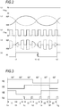
- FIG. 2 illustrates the drive voltage VReg during the DC driving
- (b) illustrates the Hall voltages HUP and HUN during the DC driving
- (c) illustrates the drive voltage VReg during the intermittent driving
- (d) illustrates the Hall voltages HUP and HUN during the intermittent driving
- (e) illustrates the Hall signal HU during the intermittent driving, respectively.
- the frequency during the intermittent driving of the drive voltage VReg is illustrated to be smaller than the actual value for the sake of explanation.
- the period during the intermittent driving of the actual drive voltage VReg is, for example, 50 ⁇ s (frequency is 20 kHz), which is sufficiently shorter than the zero-cross cycle of the Hall voltages HUP and HUN.
- the zero-cross cycle of the Hall voltages HUP and HUN is 7.5 ms.
- the Hall voltages HUP and HUN are continuously output as illustrated in FIG. 2B .
- the timing at which the zero-cross of the Hall voltage is detected is referred to as zero-cross detection timing.
- the Hall voltages HUP and HUN are output only in the period when the drive voltage VReg is applied to the Hall element 2U. Therefore, at the time t1, if the drive voltage VReg is not applied to the Hall element 2U, the zero-cross detection timing reaches the time t2 at which the drive voltage VReg is next applied. This delay leads to degradation in motor efficiency.
- the electric angle prediction unit 16 predicts the zero-cross timings of the Hall voltages output from the Hall elements 2U, 2V, and 2W respectively, and switches the driving of the Hall elements 2U, 2V, and 2W by the internal regulator 13 from the intermittent driving to the DC driving, at an predicted zero-cross timing of the Hall voltage.
- the electric angle prediction unit 16 assumes that the 3-phase brushless DC motor M rotates at a constant rotational speed, and predicts the zero-cross timing of the Hall voltage to be output from each of the Hall elements 2U, 2V, and 2W, based on the Hall signals HU, HV, and HW. Further, the electric angle prediction unit 16 instructs the internal regulator 13 to switch from the intermittent driving to the DC driving, by setting the drive switching signal Vd to the high level at the timing before the Hall voltage zero-cross. When the zero-cross of the Hall voltage is detected, the electric angle prediction unit 16 instructs the internal regulator 13 to switch from the DC driving to the intermittent driving, by setting the drive switching signal Vd to the low level.
- Hall signals HU, HV, and HW input to the electric angle prediction unit 16 are illustrated.
- the timing at which the high level and the low level are switched in the Hall signals HU, HV, and HW is the zero-cross detection timing at which the zero-cross of the Hall voltage is detected, and any of the Hall signals HU, HV, and HW switches between the high level and the low level at every electric angle of 60 degrees.
- the electric angle prediction unit 16 calculates the Hall voltage zero-cross cycle T1, that is, a time T1, in which the 3-phase brushless DC motor rotates by an electric angle of 60 degrees.
- T2 T1 * 50/60
- the drive switching signal Vd is changed to high level after about 6.25 ms (7.5 ms * 50/60) from the zero-cross detection timing. Therefore, as illustrated in FIG. 4 , the driving of the Hall elements 2U, 2V, and 2W is switched from the intermittent driving to the DC driving and the zero-cross of the Hall voltage is detected without delay.
- the timing of switching from the intermittent driving to the DC driving is set to 10 degrees before the electric angle of the predicted zero-cross timing.
- the value of the electric angle can be appropriately set in consideration of the mounting error of the Hall elements 2U, 2V, and 2W and the deviation of the zero-cross detection timing due to the change of the rotational speed based on the control signal Vsp. That is, even if the zero-cross timing deviates due to the mounting error of the Hall elements 2U, 2V, and 2W or the change in the rotational speed based on the control signal Vsp, it is preferable to switch from the intermittent driving to the DC driving before the predicted zero-cross timing so that the DC driving is performed at the zero-cross timing.
- the electric angle prediction unit 16 When the electric angle prediction unit 16 detects the zero-cross of the Hall voltage, that is, when either the Hall signals HU, HV, and HW switches between high level and low level, as illustrated in FIG. 4 , the electric angle prediction unit 16 sets the drive switching signal Vd to low level to instruct the internal regulator 13 to switch from the DC driving to the intermittent driving. As a result, current consumption is reduced.
- the measurement between the zero-cross detection timings by the electric angle prediction unit 16 and the calculation of the zero-cross cycle T1 may be performed normally and may be performed at every predetermined time or at the time of changing the rotational speed based on the control signal Vsp. If the zero-cross detection timing is measured and the zero-cross cycle T1 is calculated with intervals, it is preferable that the electric angle prediction unit 16 switches the drive switching signal Vd to the high level at the time of measuring the time between the zero-cross detection timings to perform the DC driving of the Hall elements 2U, 2V, and 2W. In this case, since it is not necessary to consider the delay of the zero-cross detection timing, the time measurement between the zero-cross detection timings and the calculation of the zero-cross cycle T1 can be accurately performed in a short time.
- a motor drive device 1 drives the 3-phase brushless DC motor M, in which Hall elements 2U, 2V, and 2W for detecting magnetic poles of the rotor and outputting a pair of Hall voltages having opposite polarities are disposed as a position detection unit detecting the position of the rotor, and includes an internal regulator 13 which functions as a Hall sensor power supply that intermittently outputs the drive voltage VReg to the Hall elements 2U, 2V, and 2W to intermittently drive the Hall elements 2U, 2V, and 2W, and an electric angle prediction unit 16 which predicts the zero-cross timing of the input Hall voltage, and, the internal regulator 13 switches to the DC driving in which a constant drive voltage VReg is output to the Hall elements 2U, 2V, and 2W during a zero-cross preceding period from before the zero-cross of the Hall voltage until the zero-cross is detected, based on the prediction result by the electric angle prediction unit 16.
- the electric angle prediction unit 16 measures the time between the zero-cross detection timings at which the zero-cross of the input Hall voltage is detected, and based on the measurement result, the electric angle prediction unit 16 instructs the internal regulator 13 to switch from the intermittent driving to the DC driving at the timing before zero-cross of the Hall voltage, and instructs the internal regulator 13 to switch from the DC driving to the intermittent driving when the zero-cross of the Hall voltage is detected.
- the electric angle prediction unit 16 measures the time between the zero-cross detection timings at intervals and instructs the interior regulator 13 to switch from the intermittent driving to the DC driving in the time for measuring a time between the zero-cross detection timings.
- an internal regulator 13a, an electric angle prediction unit 16a, and a PWM control unit 17 are different from the motor drive device 1 of the first embodiment.
- the motor drive device 1a includes a PWM control unit 17 that generates a PWM (Pulse Width Modulation) signal having a cycle of a pulse output from the oscillator (OSC) 14 at regular intervals.
- the cycle of the pulse output from the oscillator (OSC) 14 is set to a cycle sufficiently shorter than the zero-cross cycle of the Hall voltage.
- the internal regulator 13a Based on the PWM signal generated by the PWM control unit 17, the internal regulator 13a outputs the drive voltage VReg when the PWM signal is at the high level, and stops output of the drive voltage VReg when the PWM signal is at the low level. As a result, the Hall elements 2U, 2V, and 2W are intermittently driven at a cycle sufficiently shorter than the zero-cross cycle of the Hall voltage, based on the PWM signal generated by the PWM control unit 17.
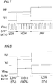
- the PWM control unit 17 changes the duty ratio of the PWM signal to be generated in accordance with the drive switching signal Vd output from the electric angle prediction unit 16a. As illustrated in FIG. 7 , the PWM control unit 17 increases the duty ratio of the PWM signal, when the drive switching signal Vd is at the high level, as compared with the case where the drive switching signal Vd is at the low level. Therefore, the period during which the output of the drive voltage VReg is stopped is shortened in the zero-cross preceding period from before the zero-cross of the Hall voltage until the zero-cross is detected. Therefore, the delay of the zero-cross detection is reduced.
- FIG. 8 illustrates an example in which the duty ratio of the PWM signal is 100% when the drive switching signal Vd is at the high level. In this case, in the zero-cross preceding period, the Hall elements 2U, 2V, and 2W are DC-driven with a constant drive voltage VReg. In addition, FIG. 8 illustrates an example in which the duty ratio of the PWM signal is 0% when the drive switching signal Vd is at the low level. In this case, during the period other than the zero-cross preceding period cycle, the Hall elements 2U, 2V, and 2W are in a stopped state in which the drive voltage VReg is not applied, and the power consumption can be further reduced.
- a control signal Vsp which indicates the rotational speed from outside is input to the electric angle prediction unit 16a.
- the rotation control unit 12 modulates the duty of the drive signal based on the instruction by the control signal Vsp and drives the drive circuit 11.
- the drive circuit 11 controls the rotational speed of the 3-phase brushless DC motor M based on the drive signal.
- the electric angle prediction unit 16a predicts the timing before the zero-cross of the Hall voltage, based on the zero-cross detection timing at which the zero-cross of the input Hall voltage is detected and the control signal Vsp. That is, the rotational speed of the 3-phase brushless DC motor M can be known by the control signal Vsp, and it is possible to predict the timing before the next zero-cross from the zero-cross detection timing.
- the electric angle prediction unit 16a switches the drive switching signal Vd to the high level at the timing before the zero-cross of the Hall voltage, and switches the drive switching signal Vd to the low level when the zero-cross of the Hall voltage is detected. Further, the electric angle prediction unit 16a may measure the time between the zero-cross detection timings and predict the timing before the zero-cross of the Hall voltage based on the measurement result.
- the electric angle prediction unit 16a compares the rotational speed of the 3-phase brushless DC motor M grasped by the control signal Vsp and the Hall signals HU, HV, and HW with the preset rotational speed threshold value, and may be configured to predict the timing before the zero-cross of the Hall voltage only when the rotational speed of the 3-phase brushless DC motor M is equal to or higher than the rotational speed threshold value. In this case, degradation of the motor efficiency can be suppressed in a region in which the rotational speed, at which the degradation of the motor efficiency becomes conspicuous, increases.
- the drive switching signal Vd from the electric angle prediction unit 16a is input to the internal regulator 13a, and during a period other than the zero-cross preceding period (a period during which the drive switching signal Vd is at the low level), the drive voltage may be lowered as compared with the zero-cross preceding period (a period during which the drive switching signal Vd is at a high level). That is, when the drive voltage is lowered, since the output levels of the Hall signals HU, HV, and HW are lowered, a possibility of erroneous detection is increased due to the influence of noise or the like. However, during a period other than the zero-cross preceding period, a little erroneous detection is allowed. Therefore, by lowering the drive voltage during the period other than the zero-cross preceding period, the power consumption can be further reduced.
- a motor drive device 1a drives the 3-phase brushless DC motor M in which Hall elements 2U, 2V, and 2W for detecting magnetic poles of the rotor and outputting a pair of Hall voltages having opposite polarities are disposed as a position detection unit detecting the position of the rotor, and includes an internal regulator 13a which functions as a Hall sensor power supply for intermittently outputting the drive voltage VReg to the Hall elements 2U, 2V, and 2W to intermittently drive the Hall elements 2U, 2V, and 2W, and an electric angle prediction unit 16a which predicts the zero-cross timing of the input Hall voltage, and the internal regulator 13a increases the duty ratio, by which the drive voltage Vreg is intermittently output, in the zero-cross preceding period from before the zero-cross of the Hall voltage to the detection of the zero-cross, as compared with the period other than the zero-cross preceding period, based on the prediction result by the electric angle prediction unit 16a.
- the internal regulator 13a sets the duty ratio to 100% in the zero-cross preceding period, and switches to the DC driving that outputs the constant drive voltage VReg to the Hall elements 2U, 2V, and 2W.
- the internal regulator 13a stops the output of the drive voltage VReg to the Hall elements 2U, 2V, and 2W by setting the duty ratio to 0% in the period other than the zero-cross preceding period.
- the internal regulator 13a lowers the drive voltage VReg in the period other than the zero-cross preceding period as compared with the zero-cross preceding period.
- the electric angle prediction unit 16a measures the time between the zero-cross detection timings at which the zero-cross of the input Hall voltage is detected, and the electric angle prediction unit 16a predicts the timing before the zero-cross of the Hall voltage, based on the measurement result.
- the electric angle prediction unit 16a predicts the timing before the zero-cross of the Hall voltage, based on the zero-cross detection timing at which the zero-cross of the input Hall voltage is detected and the control signal Vsp from the outside instructing the rotational speed.
- the Hall elements 2U, 2V, and 2W as the Hall sensors may be replaced with Hall ICs, and the plurality of Hall sensors may be connected in series.
- the Hall sensor power supply may be either a constant current source or a constant voltage source, and the resistors R1 and R2 may not be provided in accordance with the configuration of the Hall sensor power supply.
- an external clock or charging and discharging of a capacitor or the like may be used without being limited to the built-in clock.
- the present invention is applicable to a brushless DC motor drive device in which a Hall sensor is disposed as a position detection unit detecting the position of the rotor and which is used as a fan motor of an air conditioner, an air purifier, or the like.
Landscapes
- Engineering & Computer Science (AREA)
- Power Engineering (AREA)
- Physics & Mathematics (AREA)
- General Physics & Mathematics (AREA)
- Control Of Motors That Do Not Use Commutators (AREA)
Applications Claiming Priority (3)
| Application Number | Priority Date | Filing Date | Title |
|---|---|---|---|
| JP2014238816 | 2014-11-26 | ||
| JP2015166045A JP6623621B2 (ja) | 2014-11-26 | 2015-08-25 | モータ駆動装置 |
| PCT/JP2015/004931 WO2016084294A1 (ja) | 2014-11-26 | 2015-09-29 | モータ駆動装置 |
Publications (2)
| Publication Number | Publication Date |
|---|---|
| EP3226402A1 true EP3226402A1 (de) | 2017-10-04 |
| EP3226402A4 EP3226402A4 (de) | 2018-08-01 |
Family
ID=56125231
Family Applications (1)
| Application Number | Title | Priority Date | Filing Date |
|---|---|---|---|
| EP15863507.8A Withdrawn EP3226402A4 (de) | 2014-11-26 | 2015-09-29 | Motorantriebsvorrichtung |
Country Status (2)
| Country | Link |
|---|---|
| EP (1) | EP3226402A4 (de) |
| JP (1) | JP6623621B2 (de) |
Cited By (3)
| Publication number | Priority date | Publication date | Assignee | Title |
|---|---|---|---|---|
| US20210199470A1 (en) * | 2018-06-01 | 2021-07-01 | Minebea Mitsumi Inc. | Magnetic detection unit, angle detection device, position detection device, motor control device, motor unit, and motor control method |
| CN114485738A (zh) * | 2022-01-06 | 2022-05-13 | 天津中德应用技术大学 | 一种双组霍尔传感器装置及其控制方法 |
| CN115267635A (zh) * | 2022-07-04 | 2022-11-01 | 上海技涵电子科技有限公司 | 霍尔元件安装校验方法、装置、计算机设备及存储介质 |
Family Cites Families (3)
| Publication number | Priority date | Publication date | Assignee | Title |
|---|---|---|---|---|
| DE19709087A1 (de) * | 1997-03-06 | 1998-09-10 | Heidenhain Gmbh Dr Johannes | Schaltungsanordnung und Verfahren zum Betrieb für einen Positionsgeber mit Hall-Elementen |
| JP2012063211A (ja) * | 2010-09-15 | 2012-03-29 | Toshiba Corp | 磁気検出装置 |
| JP5835917B2 (ja) * | 2011-03-22 | 2015-12-24 | ローム株式会社 | モータ駆動回路、方法およびそれを用いた冷却装置、電子機器 |
-
2015
- 2015-08-25 JP JP2015166045A patent/JP6623621B2/ja active Active
- 2015-09-29 EP EP15863507.8A patent/EP3226402A4/de not_active Withdrawn
Cited By (5)
| Publication number | Priority date | Publication date | Assignee | Title |
|---|---|---|---|---|
| US20210199470A1 (en) * | 2018-06-01 | 2021-07-01 | Minebea Mitsumi Inc. | Magnetic detection unit, angle detection device, position detection device, motor control device, motor unit, and motor control method |
| CN114485738A (zh) * | 2022-01-06 | 2022-05-13 | 天津中德应用技术大学 | 一种双组霍尔传感器装置及其控制方法 |
| CN114485738B (zh) * | 2022-01-06 | 2024-01-12 | 天津中德应用技术大学 | 一种双组霍尔传感器装置及其控制方法 |
| CN115267635A (zh) * | 2022-07-04 | 2022-11-01 | 上海技涵电子科技有限公司 | 霍尔元件安装校验方法、装置、计算机设备及存储介质 |
| CN115267635B (zh) * | 2022-07-04 | 2023-10-13 | 上海技涵电子科技有限公司 | 霍尔元件安装校验方法、装置、计算机设备及存储介质 |
Also Published As
| Publication number | Publication date |
|---|---|
| JP2016111911A (ja) | 2016-06-20 |
| JP6623621B2 (ja) | 2019-12-25 |
| EP3226402A4 (de) | 2018-08-01 |
Similar Documents
| Publication | Publication Date | Title |
|---|---|---|
| JP5817021B2 (ja) | モータ駆動回路、およびそれを備えるモータユニット | |
| US9379647B2 (en) | Motor driving control device and control method of motor driving control device | |
| US20200266732A1 (en) | Motor driving control device and motor driving control method | |
| US10715063B2 (en) | Motor drive control device and method of controlling motor drive control device | |
| EP3082249A1 (de) | Motorsteuerungsvorrichtung und motorsteuerungsverfahren | |
| EP3226401A1 (de) | Motorantriebsvorrichtung | |
| EP3226402A1 (de) | Motorantriebsvorrichtung | |
| US9647584B2 (en) | Motor drive controller and control method of motor drive controller | |
| US8963467B2 (en) | Motor driving device and method of controlling the same | |
| US9685892B2 (en) | Brushless motor control device and diagnostic processing method for same | |
| WO2016084294A1 (ja) | モータ駆動装置 | |
| EP3131193A1 (de) | Leistungsumwandlungsvorrichtung und leistungsumwandlungssteuerungsverfahren | |
| US9871477B2 (en) | Motor speed control circuit and control method thereof | |
| US10256651B2 (en) | Battery charging device and method of controlling battery charging device | |
| EP3154184A1 (de) | Elektronische vorrichtung und schaltung | |
| WO2016084295A1 (ja) | モータ駆動装置 | |
| ATE450923T1 (de) | System und verfahren zum steuern eines elektrischen synchronmotors insbesondere für haushaltsgeräte | |
| US11515814B2 (en) | Motor drive control device and method for controlling the same | |
| CN104079214A (zh) | 电动机驱动装置 | |
| EP3016268A2 (de) | Motorantriebsvorrichtung, fahrzeugluftanpassungsvorrichtung und motordrehzahldetektionsverfahren | |
| JP2008043073A (ja) | ブラシレスモータの回転数制御方法、ブラシレスモータの回転数制御装置 | |
| CN118554840A (zh) | 马达驱动控制装置以及马达单元 | |
| US9106165B2 (en) | Voltage output circuit, load drive circuit, and method for outputting voltage | |
| JP5666544B2 (ja) | モータ駆動装置 | |
| JP2015070727A (ja) | モータドライバ |
Legal Events
| Date | Code | Title | Description |
|---|---|---|---|
| STAA | Information on the status of an ep patent application or granted ep patent |
Free format text: STATUS: THE INTERNATIONAL PUBLICATION HAS BEEN MADE |
|
| PUAI | Public reference made under article 153(3) epc to a published international application that has entered the european phase |
Free format text: ORIGINAL CODE: 0009012 |
|
| STAA | Information on the status of an ep patent application or granted ep patent |
Free format text: STATUS: REQUEST FOR EXAMINATION WAS MADE |
|
| 17P | Request for examination filed |
Effective date: 20170626 |
|
| AK | Designated contracting states |
Kind code of ref document: A1 Designated state(s): AL AT BE BG CH CY CZ DE DK EE ES FI FR GB GR HR HU IE IS IT LI LT LU LV MC MK MT NL NO PL PT RO RS SE SI SK SM TR |
|
| AX | Request for extension of the european patent |
Extension state: BA ME |
|
| DAV | Request for validation of the european patent (deleted) | ||
| DAX | Request for extension of the european patent (deleted) | ||
| A4 | Supplementary search report drawn up and despatched |
Effective date: 20180628 |
|
| RIC1 | Information provided on ipc code assigned before grant |
Ipc: G01D 5/14 20060101ALI20180622BHEP Ipc: H02P 6/16 20160101AFI20180622BHEP |
|
| STAA | Information on the status of an ep patent application or granted ep patent |
Free format text: STATUS: THE APPLICATION HAS BEEN WITHDRAWN |
|
| 18W | Application withdrawn |
Effective date: 20181121 |