EP3226784B1 - Drehbare medizinische vorrichtung - Google Patents
Drehbare medizinische vorrichtung Download PDFInfo
- Publication number
- EP3226784B1 EP3226784B1 EP15808315.4A EP15808315A EP3226784B1 EP 3226784 B1 EP3226784 B1 EP 3226784B1 EP 15808315 A EP15808315 A EP 15808315A EP 3226784 B1 EP3226784 B1 EP 3226784B1
- Authority
- EP
- European Patent Office
- Prior art keywords
- insert
- opening
- cutting member
- rotational atherectomy
- atherectomy device
- Prior art date
- Legal status (The legal status is an assumption and is not a legal conclusion. Google has not performed a legal analysis and makes no representation as to the accuracy of the status listed.)
- Active
Links
Images






Classifications
-
- A—HUMAN NECESSITIES
- A61—MEDICAL OR VETERINARY SCIENCE; HYGIENE
- A61B—DIAGNOSIS; SURGERY; IDENTIFICATION
- A61B17/00—Surgical instruments, devices or methods
- A61B17/32—Surgical cutting instruments
- A61B17/3205—Excision instruments
- A61B17/3207—Atherectomy devices working by cutting or abrading; Similar devices specially adapted for non-vascular obstructions
- A61B17/320758—Atherectomy devices working by cutting or abrading; Similar devices specially adapted for non-vascular obstructions with a rotating cutting instrument, e.g. motor driven
-
- A—HUMAN NECESSITIES
- A61—MEDICAL OR VETERINARY SCIENCE; HYGIENE
- A61B—DIAGNOSIS; SURGERY; IDENTIFICATION
- A61B17/00—Surgical instruments, devices or methods
- A61B2017/00831—Material properties
- A61B2017/0084—Material properties low friction
- A61B2017/00845—Material properties low friction of moving parts with respect to each other
-
- A—HUMAN NECESSITIES
- A61—MEDICAL OR VETERINARY SCIENCE; HYGIENE
- A61B—DIAGNOSIS; SURGERY; IDENTIFICATION
- A61B17/00—Surgical instruments, devices or methods
- A61B17/22—Implements for squeezing-off ulcers or the like on inner organs of the body; Implements for scraping-out cavities of body organs, e.g. bones; for invasive removal or destruction of calculus using mechanical vibrations; for removing obstructions in blood vessels, not otherwise provided for
- A61B2017/22038—Implements for squeezing-off ulcers or the like on inner organs of the body; Implements for scraping-out cavities of body organs, e.g. bones; for invasive removal or destruction of calculus using mechanical vibrations; for removing obstructions in blood vessels, not otherwise provided for with a guide wire
-
- A—HUMAN NECESSITIES
- A61—MEDICAL OR VETERINARY SCIENCE; HYGIENE
- A61B—DIAGNOSIS; SURGERY; IDENTIFICATION
- A61B17/00—Surgical instruments, devices or methods
- A61B17/32—Surgical cutting instruments
- A61B2017/320004—Surgical cutting instruments abrasive
-
- A—HUMAN NECESSITIES
- A61—MEDICAL OR VETERINARY SCIENCE; HYGIENE
- A61B—DIAGNOSIS; SURGERY; IDENTIFICATION
- A61B17/00—Surgical instruments, devices or methods
- A61B17/32—Surgical cutting instruments
- A61B2017/320052—Guides for cutting instruments
Definitions
- the disclosure is directed to devices and exemplary methods for removing occlusive material from a body lumen. More particularly, the disclosure is directed to a rotational atherectomy device for forming a passageway through an occlusion of a body lumen, such as a blood vessel.
- Occlusions can be partial occlusions that reduce blood flow through the occluded portion of a blood vessel or total occlusions (e.g., chronic total occlusions) that substantially block blood flow through the occluded blood vessel.
- Revascularization techniques include using a variety of devices to pass through the occlusion to create or enlarge an opening through the occlusion.
- Atherectomy is one technique in which a catheter having a rotatable cutting element thereon is advanced through the occlusion to form or enlarge a pathway through the occlusion.
- a guidewire is initially placed across the occlusion and then the atherectomy catheter is advanced over the guidewire as the atherectomy catheter is passed through the occlusion.
- US 6,126,667 A discloses an ablation device which has a burr assembly that is articulated to allow the burr to rotate relative to a longitudinal axis of the driveshaft.
- the burr is formed in two parts.
- An inner burr member is coupled to a rotatable driveshaft and has an arcuate region distal to the driveshaft.
- An outer burr member has an inner cavity in which the inner burr member is positioned.
- the disclosure is directed to several alternative designs, materials and methods of manufacturing medical device structures and assemblies, and exemplary uses thereof.
- the rotational atherectomy device of the invention is defined in claim 1. Preferred embodiments are defined in the dependent claims.
- the rotational atherectomy device includes an outer tubular member having a lumen extending therethrough, a cutting member rotationally positioned at a distal end of the outer tubular member, and a drive shaft extending through the lumen of the outer tubular member.
- the cutting member includes a central longitudinal bore extending therethrough. A distal end region of the drive shaft extends into the bore of the cutting member.
- the drive shaft is rotatable relative to the outer tubular member to rotate the cutting member.
- the rotational atherectomy device further includes an insert positioned within the bore of the cutting member. The insert includes an opening extending therethrough axially aligned with the bore of the cutting member.
- the drive shaft includes a guidewire lumen extending therethrough axially aligned with the opening of the insert.
- the guidewire lumen has a diameter and the opening of the insert has a diameter less than the diameter of the guidewire lumen.
- the cutting member includes a distal opening axially aligned with the opening of the insert, the distal opening of the cutting member having a diameter greater than or equal to a diameter of the opening of the insert.
- the insert includes an inner surface defining the opening of the insert, wherein at least a portion of the inner surface is nonparallel to a central longitudinal axis of the drive shaft.
- the insert includes an inner surface defining the opening of the insert, the inner surface having a surface roughness R a of 0.4 micrometers or less.
- Another illustrative example is a method, not forming part of the invention, of creating or enlarging a passageway through an occlusion in a body lumen.
- the method includes advancing a guidewire through a body lumen to a location proximate an occlusion and then advancing a rotational atherectomy device through the body lumen over the guidewire to a location proximal of the occlusion in the body lumen.
- the rotational atherectomy device includes a rotatable drive shaft extending through an outer tubular member to rotatably drive a cutting member positioned at a distal end of the outer tubular member, and an insert positioned within the cutting member.
- the guidewire extends through an opening of the insert and a guidewire lumen of the drive shaft.
- the method further includes rotating the cutting member relative to the guidewire with the drive shaft while advancing the cutting member through the occlusion.
- a coefficient of static friction between the insert and the guidewire is less than 0.25.
- a coefficient of static friction between the insert and the guidewire is less than 0.10.
- the rotational atherectomy system 10 may include a rotational atherectomy device 12 and a controller 14 for controlling the rotational atherectomy device 12.
- the rotational atherectomy device 12 may include a housing 16 and an elongate shaft 18 extending distally from the housing 16 to a cutting member 20 located at a distal end of the elongate shaft 18.
- the elongate shaft 18 may include a drive shaft 24 to provide rotational motion to the cutting member 20.
- the elongate shaft 18 may include an outer tubular member 22 having a lumen extending therethrough and the drive shaft 24 may extend through the lumen of the outer tubular member 22.
- the drive shaft 24, which may be fixed to the cutting member 20, may be rotatable relative to the outer tubular member 22 to rotate the cutting member 20.
- the axial position of the cutting member 20 relative to the outer tubular member 22 may be adjusted by moving the drive shaft 24 longitudinally relative to the outer tubular member 22.
- the atherectomy device 12 may include an advancer assembly 26 positioned in the housing 16, or otherwise provided with the housing 16, that is longitudinally movable relative to the housing 16.
- the outer tubular member 22 may be coupled to the housing 16 while the drive shaft 24 may be coupled to the advancer assembly 26. Accordingly, the drive shaft 24 (and thus the cutting member 20) may be longitudinally movable relative to the outer tubular member 22 by actuating the advancer assembly 26 relative to the housing 16.
- the rotational atherectomy device 12 may include a prime mover (not shown) to provide rotational motion to the drive shaft 24 to rotate the cutting member 20.
- the prime mover may be a fluid turbine within the housing 16, such as provided with the advancer assembly 26. In other instances, however, the prime mover may be an electrical motor, or the like.
- the controller 14 may be used to control the prime mover.
- the user may provide power to the prime mover and/or control the speed of rotation of the drive shaft 24 via the controller 14.
- the front panel 28 of the controller 14 may include a user interface including a power switch, speed control mechanism (e.g., a speed control knob and/or buttons), a display, and/or other features for controlling the rotational atherectomy device 12.
- the rotational atherectomy system 10 may include a remote control device 30, such as a foot pedal, a hand control, or other mechanism which may be used to control the power and/or speed to the prime mover, for example.
- the rotational atherectomy system 10 may also include a pressurized fluid source 32 providing a pressurized fluid to the turbine to rotate the drive shaft 24.
- the pressurized fluid source 32 may be a tank of pressurized fluid (e.g., compressed air), which may or may not include an air compressor.
- the pressured fluid source 32 may be provided external of the rotational atherectomy system 10, such as from a wall outlet at the medical facility.
- the pressured fluid source 32 may be coupled to the controller 14 via a fluid conduit 34, which in turn is coupled to the rotational atherectomy device 12 via a fluid conduit 36.
- the controller 14 may regulate the flow and/or pressure of fluid through the fluid conduit 36 to the rotational atherectomy device 12 to control the speed of rotation of the drive shaft 24 and cutting member 20, for instance.
- the electric motor may be coupled to the controller 14 via an electrical connection to control the electric motor and/or provide electricity to the electric motor.
- the rotational atherectomy device 12 may include a speed sensor, such as an optical speed sensor, coupled to the controller 14 via a connector 38, such as a fiber optic connector to provide speed data to the controller 14.
- a speed sensor such as an optical speed sensor
- an electronic sensor such as a Hall Effect sensor, or other type of sensor may be used to sense the speed of the drive shaft 24 and cutting member 20.
- the speed data may be displayed, such as on the front panel 28 and/or the controller 14, and/or used to control the speed of the cutting member 20, such as maintaining a desired speed of the cutting member 20 during a medical procedure.
- the rotational atherectomy system 10 may be configured to infuse fluid through the elongate shaft 18 to the treatment site and/or aspirate fluid through the elongate shaft 18 from the treatment site.
- the rotational atherectomy system 10 may include a fluid supply 40 for providing a flow of fluid through a lumen of the elongate shaft 18 to a treatment site.
- the fluid supply 40 may include a saline bag 42 which may be pressurized by a pressure cuff 44 to provide a pressurized fluid (e.g., saline) to the rotational atherectomy device 12 through a fluid supply line 46.
- an infusion pump such as a peristaltic pump
- a peristaltic pump may be used to deliver pressurized fluid to the rotational atherectomy device 12.
- the rotational atherectomy system 10 may be configured to aspirate fluid from the treatment site.
- the rotational atherectomy system 10 may include an aspiration pump, such as a peristaltic pump, to generate a vacuum to aspirate fluid through a lumen of the elongate shaft 18 to a fluid collection container (not shown), if desired.
- the elongate shaft 18 of the rotational atherectomy device 12 may be advanced over a guidewire 48 to a treatment site.
- the drive shaft 24 may include a guidewire lumen through which the guidewire 48 may pass.
- the elongate shaft 18 may be advanced through a lumen of a guide catheter to a treatment site.
- the drive shaft 24 which in some instances may include a coiled member, may extend through the lumen 72 of the outer tubular member 22 and be rotationally and/or longitudinally movable relative to the outer tubular member 22.
- the drive shaft 24 may include the cutting member 20 mounted thereon.
- the cutting member 20 may be a burr having an abrasive surface, such as a diamond coated abrasive surface.
- the cutting member 20 may include one or more flutes having a cutting edge, or the cutting member 20 may be of another construction for abrading or cutting occlusive material.
- a guidewire lumen 60 may extend through the drive shaft 24 and the cutting member 20 to a distal tip 70 of the cutting member 20.
- the cutting member 20 may include a bore 62 extending therethrough with a distal end region of the drive shaft 24 extending into the bore 62 of the cutting member 20.
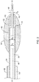
- the rotational atherectomy device 12 may also include an insert 50 positioned within the cutting member 20.
- the insert 50 may be positioned in the bore 62 of the cutting member 20 distal of a distal end 25 of the drive shaft 24.
- the insert 50 may include an opening 52 extending therethrough for passing the guidewire 48 therethrough.
- the opening 52 through the insert 50 may be axially aligned with the guidewire lumen 60 of the drive shaft 24.
- the opening 52 may be coaxial with the guidewire lumen 60 in some instances.
- the guidewire lumen 60 may have a diameter D 1 and the opening 52 through the insert 50 may have a diameter D 2 .
- the diameter D 1 of the guidewire lumen 60 may be greater than the diameter D 2 of the opening 52. Accordingly, there may be a closer tolerance between an inner surface of the insert 50 and the guidewire 48 than the tolerance between the guidewire 48 and the drive shaft 24. In other words, there may be greater clearance between the guidewire 48 and the inner surface of the drive shaft 24 than the clearance between the guidewire 48 and the inner surface of the insert 50 defining the opening 52.
- the guidewire lumen 60 may have a diameter D 1 of about 0.41 millimeters (0.016 inches) or more, or about 0.46 millimeters (0.018 inches) or more, while the diameter D 2 of the opening 52 of the insert 50 may be about 0.38 millimeters (0.015 inches).
- the bore 62 within which the insert 50 and/or the distal end region of the drive shaft 24 may be disposed, may have a diameter D 3 .
- the diameter D 3 of the bore 62 may be greater than the diameter D 1 of the guidewire lumen 60 through the drive shaft 24 and/or the opening 52 through the insert 50.
- the insert 50 may be inserted into the bore 62 of the cutting member 20 from the proximal opening of the cutting member 20.
- the distal end region of the drive shaft 24 may be inserted into the bore 62 of the cutting member 20 from the proximal opening of the cutting member 20.
- the distal end 25 of the drive shaft 24 may face or abut the proximal end of the insert 50 within the bore 62 of the cutting member 20.
- the cutting member 20 may include a distal opening at the distal tip 70 of the cutting member 20.
- the distal opening of the cutting member 20 may be axially aligned with the opening 52 of the insert 50.
- the distal opening of the cutting member 20 may have a diameter greater than or equal to the diameter D 2 of the opening 52 of the insert 50.
- the distal opening of the cutting member 20 may be configured to facilitate inserting the guidewire 48 into the opening 52 of the insert 50 and through the guidewire lumen 62 of the drive shaft 24 from the distal tip 70 of the cutting member 20.
- the insert 50 may function as a spacer and/or bearing between the cutting member 20 and the guidewire 48.
- the insert 50 may provide a low friction interface with the guidewire 48 as the cutting member 20 is rotatably driven during a medical procedure.
- the inner surface of the insert 50 which defines the opening 52 of the insert 50 may have an average surface roughness R a of about 0.4 micrometers or less, about 0.3 micrometers or less, about 0.2 micrometers or less, or about 0.1 micrometers or less. Additionally or alternatively, in some instances the coefficient of static friction ⁇ s between the insert 50 and the guidewire 48 may be less than 0.25, less than 0.20, less than 0.15 or less than 0.10, for example.
- the insert 50 may be made of any desired material, such as a low friction material, including a metallic material, a polymeric material, or a combination thereof.
- a metallic material include stainless steel, such as highly polished stainless steel.
- suitable polymeric materials include polyamide (e.g., nylon), polytetrafluoroethylene (PTFE), high density polyethylene (HDPE), ultra-high molecular weight polyethylene (UHMWPE), or other polymeric material having a high molecular weight, for example.
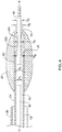
- an insert 150 may be positioned within the cutting member 20.
- the insert 150 may be positioned in the bore 62 of the cutting member 20 distal of a distal end 25 of the drive shaft 24.
- the insert 150 may include an opening 152 extending therethrough for passing the guidewire 48 therethrough.
- the opening 152 through the insert 150 may be axially aligned with the guidewire lumen 60 of the drive shaft 24.
- the opening 152 may be coaxial with the guidewire lumen 60 in some instances.
- the insert 150 may include an inner surface defining the opening 152 of the insert 150. As shown in FIG. 3 , at least a portion of the inner surface of the insert 150 may be nonparallel to the central longitudinal axis X of the drive shaft 24. For example, the inner surface of the insert 150 may taper radially outward from the central longitudinal axis in a distal direction (i.e., flare radially outward toward the distal tip 70) along at least a portion of the longitudinal length of the opening 152.
- a proximal region and/or mid region of the opening 152 may have a diameter D 2
- a distal region of the opening 152 may have a diameter D 4 greater than the diameter D 2 of the proximal region and/or mid region of the opening 152.
- the insert 150 may be similar to the insert 50 described above.
- the insert 150 may function as a spacer and/or bearing between the cutting member 20 and the guidewire 48.
- the insert 150 may provide a low friction interface with the guidewire 48 as the cutting member 20 is rotatably driven during a medical procedure.
- the inner surface of the insert 150 which defines the opening 152 of the insert 150 may have an average surface roughness R a of about 0.4 micrometers or less, about 0.3 micrometers or less, about 0.2 micrometers or less, or about 0.1 micrometers or less. Additionally or alternatively, in some instances the coefficient of static friction ⁇ s between the insert 150 and the guidewire 48 may be less than 0.25, less than 0.20, less than 0.15 or less than 0.10, for example.
- the insert 150 may be made of any desired material, such as a low friction material, including a metallic material, a polymeric material, or a combination thereof.
- a metallic material include stainless steel, such as highly polished stainless steel.
- suitable polymeric materials include polyamide (e.g., nylon), polytetrafluoroethylene (PTFE), high density polyethylene (HDPE), ultra-high molecular weight polyethylene (UHMWPE), or other polymeric material having a high molecular weight, for example.
- the distal opening of the cutting member 20 at the distal tip 70 may have a diameter D 5 greater than the diameter D 4 of the distal region of the opening 152, and thus greater than the diameter D 2 of the proximal region and/or mid region of the opening 152.
- the enlarged diameter of the distal opening of the cutting member 20 may facilitate inserting the guidewire 48 into the opening 152 of the insert 150 and through the guidewire lumen 62 of the drive shaft 24 from the distal tip 70 of the cutting member 20.
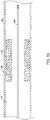
- an insert 250 may be positioned within the cutting member 20.
- the insert 250 may be positioned in the bore 62 of the cutting member 20 distal of a distal end 25 of the drive shaft 24.
- the insert 250 may include an opening 252 extending therethrough for passing the guidewire 48 therethrough.
- the opening 252 through the insert 250 may be axially aligned with the guidewire lumen 60 of the drive shaft 24.
- the opening 252 may be coaxial with the guidewire lumen 60 in some instances.
- the insert 250 may include an inner surface defining the opening 252 of the insert 250. As shown in FIG. 4 , at least a portion of the inner surface of the insert 250 may be nonparallel to the central longitudinal axis X of the drive shaft 24. For example, the inner surface of the insert 250 may taper radially outward from the central longitudinal axis in a distal direction (i.e., flare radially outward toward the distal tip 70) along at least a portion of the longitudinal length of the opening 252. For example, a mid region of the opening 252 may have a diameter D 2 , while a distal region of the opening 252 may have a diameter D 4 greater than the diameter D 2 of the mid region of the opening 252.
- the inner surface of the insert 250 may taper radially outward from the central longitudinal axis in a proximal direction (i.e., flare radially outward toward the proximal end of the insert 250) along at least a portion of the longitudinal length of the opening 252.
- a proximal region of the opening 252 may have a diameter D 6 greater than the diameter D 2 of the mid region of the opening 252.
- the diameter D 6 of the proximal region of the opening 252 may be the same as the diameter D 4 of the distal region of the opening 252, or the diameter D 6 may be different than (e.g., greater than or less than) the diameter D 4 .
- the insert 250 may be similar to the insert 50 described above.
- the insert 250 may function as a spacer and/or bearing between the cutting member 20 and the guidewire 48.
- the insert 250 may provide a low friction interface with the guidewire 48 as the cutting member 20 is rotatably driven during a medical procedure.
- the inner surface of the insert 250 which defines the opening 252 of the insert 250 may have an average surface roughness R a of about 0.4 micrometers or less, about 0.3 micrometers or less, about 0.2 micrometers or less, or about 0.1 micrometers or less. Additionally or alternatively, in some instances the coefficient of static friction ⁇ s between the insert 250 and the guidewire 48 may be less than 0.25, less than 0.20, less than 0.15 or less than 0.10, for example.
- the insert 250 may be made of any desired material, such as a low friction material, including a metallic material, a polymeric material, or a combination thereof.
- a metallic material include stainless steel, such as highly polished stainless steel.
- suitable polymeric materials include polyamide (e.g., nylon), polytetrafluoroethylene (PTFE), high density polyethylene (HDPE), ultra-high molecular weight polyethylene (UHMWPE), or other polymeric material having a high molecular weight, for example.
- the distal opening of the cutting member 20 at the distal tip 70 may have a diameter D 5 greater than the diameter D 4 of the distal region of the opening 252, and thus greater than the diameter D 2 of the mid region of the opening 252.
- the enlarged diameter of the distal opening of the cutting member 20 may facilitate inserting the guidewire 48 into the opening 252 of the insert 250 and through the guidewire lumen 62 of the drive shaft 24 from the distal tip 70 of the cutting member 20.
- an insert 350 may be positioned within the cutting member 20.
- the insert 350 may be positioned in the bore 62 of the cutting member 20 within the distal end region of the drive shaft 24.
- the insert 350 may include an opening 352 extending therethrough for passing the guidewire 48 therethrough.
- the opening 352 through the insert 350 may be axially aligned with the guidewire lumen 60 of the drive shaft 24.
- the opening 352 may be coaxial with the guidewire lumen 60 in some instances.
- the insert 350 may include an inner surface defining the opening 352 of the insert 350. As shown in FIG. 5 , at least a portion of the inner surface of the insert 350 may be nonparallel to the central longitudinal axis X of the drive shaft 24. For example, the inner surface of the insert 350 may taper radially outward from the central longitudinal axis in a distal direction (i.e., flare radially outward toward its distal end) along at least a portion of the longitudinal length of the opening 352 and/or may taper radially outward from the central longitudinal axis in a proximal direction (i.e., flare radially outward toward its proximal end). For example, a mid region of the opening 352 may have a diameter D 2 , while a proximal region and/or a distal region of the opening 352 may have a diameter greater than the diameter D 2 of the mid region of the opening 352.
- the insert 350 may be similar to the insert 50 described above.
- the insert 350 may function as a spacer and/or bearing between the cutting member 20 and the guidewire 48.
- the insert 350 may provide a low friction interface with the guidewire 48 as the cutting member 20 is rotatably driven during a medical procedure.
- the inner surface of the insert 350 which defines the opening 352 of the insert 350 may have an average surface roughness R a of about 0.4 micrometers or less, about 0.3 micrometers or less, about 0.2 micrometers or less, or about 0.1 micrometers or less. Additionally or alternatively, in some instances the coefficient of static friction ⁇ s between the insert 350 and the guidewire 48 may be less than 0.25, less than 0.20, less than 0.15 or less than 0.10, for example.
- the insert 350 may be made of any desired material, such as a low friction material, including a metallic material, a polymeric material, or a combination thereof.
- a metallic material include stainless steel, such as highly polished stainless steel.
- suitable polymeric materials include polyamide (e.g., nylon), polytetrafluoroethylene (PTFE), high density polyethylene (HDPE), ultra-high molecular weight polyethylene (UHMWPE), or other polymeric material having a high molecular weight, for example.
- the distal opening of the cutting member 20 at the distal tip 70 may have a diameter D 5 greater than the diameter D 2 of the opening 352.
- the enlarged diameter of the distal opening of the cutting member 20 may facilitate inserting the guidewire 48 into the opening 352 of the insert 350 and through the guidewire lumen 62 of the drive shaft 24 from the distal tip 70 of the cutting member 20.
- the bore 62 of the cutting member 20 may include a stepped region between the diameter D3 and the diameter D4.
- the distal end 25 of the drive shaft 24 and/or the distal end of the insert 350 may be positioned adjacent to and/or abut the stepped region of the bore 62.
- central longitudinal axis of the cutting member 20 and the central longitudinal axis of the insert 50, 150, 250, 350 are shown in FIGS. 2-5 as being coaxial with the central longitudinal axis X (i.e., the rotational axis) of the drive shaft 24, in other instances, the central longitudinal axis of the cutting member 20 and/or the central longitudinal axis of the insert 50, 150, 250, 350 may be non-coaxial with the central longitudinal axis X of the drive shaft 24, allowing for eccentric rotation of the cutting member 20 while still providing a smooth bearing surface inside the cutting member 20 for the guidewire 48.
- a guidewire 48 may be advanced through the lumen 94 of the blood vessel 90 to a location proximate an occlusion 92.
- the guidewire 48 may be advanced through the occlusion 92 such that the distal end of the guidewire 48 passes distally beyond the occlusion 92.
- the rotational atherectomy device 12 may then be advanced through the lumen 94 of the blood vessel 90 over the guidewire 48 to a location proximate the occlusion 92 to create or enlarge a passageway through the occlusion 92.
- the elongate shaft 18 of the rotational atherectomy device 12 may be advanced through a body lumen (e.g., blood vessel 90) to a location proximal of the occlusion 92 in the body lumen.
- the guidewire 48 may pass into the distal opening of the cutting member 20, through the opening 52, 152, 252, 352 of the insert 50, 150, 250, 350 within the cutting member 20, and through the guidewire lumen 60 of the drive shaft 24, as shown in FIGS. 2-5 .
- the elongate shaft 18 may be advanced through a lumen of a guide catheter to the occlusion 92 while being advanced along the guidewire 48.
- the rotational atherectomy device 12 may be used to create or enlarge a passageway through the occlusion 92. For example, referring to FIG. 8 , thereafter, rotation of the cutting member 20 (via rotationally driving the drive shaft 24) may be initiated once the cutting member 20 has been advanced to the occlusion 92.
- the rotatable drive shaft 24 extending through the outer tubular member 22 of the elongate shaft 18 of the rotational atherectomy device 12 may be rotatably driven to rotatably drive the cutting member 20 while advancing the cutting member 20 through the occlusion 92.
- the drive shaft 24 may be advanced distally relative to the outer tubular member 22 to advance the cutting member 20 through the occlusion 92, while in other instances the outer tubular member 22 may be advanced together with the drive shaft 24.
- fluid infusion and/or fluid aspiration through one or more lumens of the rotational atherectomy device 12 may be performed while advancing the cutting member 20 through the occlusion 92.
- the insert 50, 150, 250, 350 may function as a bearing as the cutting member 20 rotates at a high rotational rate, e.g., 5,000 revolutions per minute (RPM) or more, 10,000 revolutions per minute (RPM) or more, or 20,000 revolutions per minute (RPM) or more) about the guidewire 48.
- the insert 50, 150, 250, 350 may maintain the guidewire 48 spaced away from directly contacting the cutting member 20 as the cutting member 20 is being rotated about its rotational axis.
- the frictional interaction between the guidewire 48 and the insert 50 may be less than that between the guidewire 48 and the cutting member 20 if permitted to frictionally contact one another.
- the coefficient of static friction ⁇ s between the insert 50, 150, 250, 350 and the guidewire 48 may be less than 0.25, less than 0.20, less than 0.15 or less than 0.10, for example.
- the cutting member 20 may be advanced through the occlusion 92 to form or enlarge a pathway 96 through the occlusion 92 to permit blood flow through the lumen 94 of the blood vessel 90, as shown in FIG. 9 . Thereafter, as shown in FIG. 10 , the rotational atherectomy device 12 may be withdrawn, leaving the guidewire 48 in position across the occlusion 92.
- Another intravascular device such as a therapeutic or diagnostic medical device, may then be advanced over the guidewire 48 to a location proximate to or distal of the occlusion 92, for example. For instance, as shown in FIG.
- an angioplasty catheter 100 may be advanced over the previously positioned guidewire 48 to position an inflatable balloon 120 of the angioplasty catheter 100 across the occlusion 92.
- the balloon 120 may then be inflated with an inflation media introduced into the balloon 120 from an inflation lumen extending through the elongate shaft 110 of the angioplasty catheter 100 to further enlarge the passageway through the occlusion 92.
- the same guidewire 48 may be used throughout the procedure without the need to exchange the guidewire 48 for one or more other guidewires.
- the same guidewire 48 used to initially cross the occlusion 92 may also be used in advancing the rotational atherectomy device 12 distally through the occlusion 92 and/or in advancing one or more additional intravascular devices proximate to or distally through the occlusion 92.
- the ability to utilize the same guidewire 48 without performing a guidewire exchange may save time during the procedure as well as reduce the number of medical devices needed to complete the procedure.
- the rotational cutting devices described herein may be used in other medical procedures, such as in orthopedic medical procedures, if desired.
- the penetrating member may be penetrated into a bony structure to stabilize the cutting member prior to initiating engagement of the rotating cutting member with the bony structure.
Landscapes
- Health & Medical Sciences (AREA)
- Surgery (AREA)
- Life Sciences & Earth Sciences (AREA)
- Biomedical Technology (AREA)
- Nuclear Medicine, Radiotherapy & Molecular Imaging (AREA)
- Engineering & Computer Science (AREA)
- Vascular Medicine (AREA)
- Heart & Thoracic Surgery (AREA)
- Medical Informatics (AREA)
- Molecular Biology (AREA)
- Animal Behavior & Ethology (AREA)
- General Health & Medical Sciences (AREA)
- Public Health (AREA)
- Veterinary Medicine (AREA)
- Surgical Instruments (AREA)
Claims (15)
- Rotationsatherektomievorrichtung mit:einem äußeren rohrförmigen Element (22) mit einem sich durch dieses erstreckenden Lumen (72);einem Schneidelement (20), das an einem distalen Ende des äußeren rohrförmigen Elements drehbar angeordnet ist;einer Antriebswelle (24), die sich durch das Lumen des äußeren rohrförmigen Elements erstreckt, wobei die Antriebswelle relativ zum äußeren rohrförmigen Element drehbar ist, um das Schneidelement zu drehen; undeinem Einsatz (150, 250, 350), der innerhalb des Schneidelements angeordnet ist, wobei der Einsatz eine sich durch diesen erstreckende Öffnung (152, 252, 352) aufweist, die dafür vorgesehen ist, einen Führungsdraht (48) hindurchzuführen, wobei der Einsatz eine Innenfläche aufweist, die die Öffnung (152, 252, 352) des Einsatzes definiert, wobei mindestens ein Teil der Innenfläche nicht parallel zu einer mittigen Längsachse der Antriebswelle ausgerichtet ist, wobei das Schneidelement (20) eine distale Öffnung aufweist, die axial mit der Öffnung des Einsatzes ausgerichtet ist, wobei die distale Öffnung des Schneidelements einen Durchmesser (D4) hat, der größer ist als ein Durchmesser (D2) der Öffnung des Einsatzes.
- Rotationsatherektomievorrichtung nach Anspruch 1, wobei ein distaler Abschnitt der Antriebswelle (24) sich in eine Öffnung (62) des Schneidelements (20) erstreckt.
- Rotationsatherektomievorrichtung nach Anspruch 2, wobei der Einsatz (150, 250) in der Öffnung (62) des Schneidelements (20) distal von einem distalen Ende (25) der Antriebswelle (24) angeordnet ist.
- Rotationsatherektomievorrichtung nach Anspruch 2 oder 3, wobei die Antriebswelle (24) ein sich durch diese erstreckendes Führungsdrahtlumen (62) aufweist, das mit der Öffnung (152, 252, 352) des Einsatzes (150, 250, 350) axial ausgerichtet ist.
- Rotationsatherektomievorrichtung nach Anspruch 4, wobei das Führungsdrahtlumen (62) einen Durchmesser (D1) hat und die Öffnung (152, 252, 352) des Einsatzes (150, 250, 350) einen Durchmesser (D2) hat, der kleiner ist als der Durchmesser des Führungsdrahtlumens.
- Rotationsatherektomievorrichtung nach einem der Ansprüche 2 bis 5, wobei die Öffnung (62) einen Durchmesser (D3) hat, der größer ist als der Durchmesser (D2) der Öffnung (152, 252, 352) des Einsatzes (150, 250, 350).
- Rotationsatherektomievorrichtung nach einem der vorangehenden Ansprüche, wobei sich die Innenfläche von der mittigen Längsachse in einer distalen Richtung radial nach außen erweitert.
- Rotationsatherektomievorrichtung nach Anspruch 7, wobei sich die Innenfläche in einer distalen Richtung von einem Mittenbereich des Einsatzes (250, 350) zu einer distalen Spitze des Einsatzes radial nach außen erweitert.
- Rotationsatherektomievorrichtung nach einem der vorangehenden Ansprüche, wobei sich die Innenfläche von der mittigen Längsachse in einer proximalen Richtung radial nach außen erweitert.
- Rotationsatherektomievorrichtung nach Anspruch 8, wobei sich die Innenfläche vom Mittenbereich des Einsatzes (250, 350) zu einem proximalen Ende des Einsatzes in einer proximalen Richtung radial nach außen erweitert.
- Rotationsatherektomievorrichtung nach einem der vorangehenden Ansprüche, wobei der Einsatz (150, 250, 350) eine Innenfläche aufweist, die die Öffnung des Einsatzes definiert, wobei die Innenfläche eine Oberflächenrauheit Ra von 0,4 µm oder weniger aufweist.
- Rotationsatherektomievorrichtung nach einem der vorangehenden Ansprüche, wobei der Einsatz (150, 250, 350) eine Innenfläche aufweist, die die Öffnung des Einsatzes definiert, wobei die Innenfläche eine Oberflächenrauheit Ra von 0,2 µm oder weniger aufweist.
- Rotationsatherektomievorrichtung nach einem der vorangehenden Ansprüche, wobei ein distales Ende (25) der Antriebswelle (24) an einem proximalen Ende des Einsatzes (150, 250) anliegt.
- Rotationsatherektomievorrichtung nach einem der vorangehenden Ansprüche, wobei der Einsatz (150, 250, 350) aus einem Polymermaterial besteht.
- Rotationsatherektomievorrichtung nach einem der Ansprüche 1 bis 13, wobei der Einsatz (150, 250, 350) aus einem polierten Metallmaterial besteht.
Applications Claiming Priority (2)
| Application Number | Priority Date | Filing Date | Title |
|---|---|---|---|
| US201462087531P | 2014-12-04 | 2014-12-04 | |
| PCT/US2015/063154 WO2016089847A1 (en) | 2014-12-04 | 2015-12-01 | Rotatable medical device |
Publications (2)
| Publication Number | Publication Date |
|---|---|
| EP3226784A1 EP3226784A1 (de) | 2017-10-11 |
| EP3226784B1 true EP3226784B1 (de) | 2020-09-09 |
Family
ID=54848912
Family Applications (1)
| Application Number | Title | Priority Date | Filing Date |
|---|---|---|---|
| EP15808315.4A Active EP3226784B1 (de) | 2014-12-04 | 2015-12-01 | Drehbare medizinische vorrichtung |
Country Status (3)
| Country | Link |
|---|---|
| US (4) | US10405879B2 (de) |
| EP (1) | EP3226784B1 (de) |
| WO (1) | WO2016089847A1 (de) |
Cited By (4)
| Publication number | Priority date | Publication date | Assignee | Title |
|---|---|---|---|---|
| US12171457B2 (en) | 2020-10-30 | 2024-12-24 | Boston Scientific Scimed, Inc. | Atherectomy burrs with blood flow enhancements |
| US12539139B2 (en) | 2021-08-16 | 2026-02-03 | Boston Scientific Scimed, Inc. | Atherectomy system with reusable portion and single use portion |
| US12594092B2 (en) | 2021-10-20 | 2026-04-07 | Boston Scientific Scimed, Inc. | Fly by wire control for atherectomy |
| US12616496B2 (en) | 2021-08-27 | 2026-05-05 | Boston Scientific Scimed, Inc. | Atherectomy system with anterograde and retrograde ablation |
Families Citing this family (21)
| Publication number | Priority date | Publication date | Assignee | Title |
|---|---|---|---|---|
| US10639062B2 (en) | 2016-04-06 | 2020-05-05 | Cardio Flow, Inc. | Atherectomy devices and methods |
| US10448971B2 (en) | 2016-12-21 | 2019-10-22 | Medtronic, Inc. | Apparatus for forming a passageway in tissue and associated interventional medical systems |
| US11690645B2 (en) | 2017-05-03 | 2023-07-04 | Medtronic Vascular, Inc. | Tissue-removing catheter |
| US10987126B2 (en) * | 2017-05-03 | 2021-04-27 | Medtronic Vascular, Inc. | Tissue-removing catheter with guidewire isolation liner |
| US10786278B2 (en) * | 2017-05-31 | 2020-09-29 | Terumo Kabushiki Kaisha | Medical device and method |
| US12053204B2 (en) | 2017-05-31 | 2024-08-06 | Terumo Kabushiki Kaisha | Medical device and method |
| US11382652B2 (en) * | 2018-05-08 | 2022-07-12 | Boston Scientific Scimed, Inc. | Device guidewire management accessory |
| WO2020033260A1 (en) | 2018-08-07 | 2020-02-13 | Cardio Flow, Inc. | Atherectomy devices and methods |
| WO2020055728A1 (en) | 2018-09-10 | 2020-03-19 | Medtronic Vascular, Inc. | Tissue-removing catheter with guidewire detection sensor |
| CN118697424A (zh) | 2018-11-16 | 2024-09-27 | 美敦力瓦斯科尔勒公司 | 组织去除导管 |
| EP3909513B1 (de) * | 2019-01-09 | 2024-09-11 | Zeon Corporation | Endoskopische punktionsvorrichtung |
| US11266437B2 (en) * | 2019-04-15 | 2022-03-08 | Cardiovascular Systems, Inc. | Drive shaft with metallic inner layer and polymer jacket |
| US11819236B2 (en) | 2019-05-17 | 2023-11-21 | Medtronic Vascular, Inc. | Tissue-removing catheter |
| CN110985521B (zh) * | 2019-09-27 | 2025-04-04 | 上海微创旋律医疗科技有限公司 | 旋转装置以及用于旋转装置的驱动轴 |
| EP4061257A1 (de) * | 2019-11-20 | 2022-09-28 | Boston Scientific Scimed, Inc. | Zusammengesetzter atherektomiebohrer |
| CN111513818A (zh) * | 2020-05-12 | 2020-08-11 | 安徽一升医疗设备有限公司 | 一种用于治疗冠状动脉钙化病变的旋磨介入治疗仪 |
| US12544099B2 (en) * | 2021-04-01 | 2026-02-10 | Medtronic Vascular, Inc. | Tissue-removing catheter with coupled inner liner |
| US12605184B2 (en) | 2021-08-23 | 2026-04-21 | Medtronic Vascular, Inc. | Tissue-removing catheter with distal tip |
| CN114916997B (zh) * | 2022-05-31 | 2025-11-04 | 上海微创旋律医疗科技有限公司 | 旋磨装置及旋磨设备 |
| CN114948107A (zh) * | 2022-06-20 | 2022-08-30 | 上海微创旋律医疗科技有限公司 | 旋磨装置 |
| WO2025069615A1 (ja) * | 2023-09-29 | 2025-04-03 | テルモ株式会社 | 医療デバイス |
Family Cites Families (146)
| Publication number | Priority date | Publication date | Assignee | Title |
|---|---|---|---|---|
| US4684361A (en) | 1985-10-11 | 1987-08-04 | Cardiovascular Systems, Inc. | Centrifuge |
| US3043314A (en) | 1958-09-15 | 1962-07-10 | Frank T Bartolomeo | Smoking articles |
| US4445509A (en) | 1982-02-04 | 1984-05-01 | Auth David C | Method and apparatus for removal of enclosed abnormal deposits |
| US5041082A (en) | 1986-06-16 | 1991-08-20 | Samuel Shiber | Mechanical atherectomy system and method |
| US4692136A (en) | 1985-10-11 | 1987-09-08 | Cardiovascular Systems Inc. | Centrifuge |
| CA1293663C (en) | 1986-01-06 | 1991-12-31 | David Christopher Auth | Transluminal microdissection device |
| US4718888A (en) | 1986-03-10 | 1988-01-12 | Cardiovascular Systems, Inc. | Centrifuge bowl mount |
| US5314407A (en) | 1986-11-14 | 1994-05-24 | Heart Technology, Inc. | Clinically practical rotational angioplasty system |
| US5221258A (en) | 1991-01-22 | 1993-06-22 | Shturman Technologies, Inc. | Introduction balloon catheter |
| US5295958A (en) | 1991-04-04 | 1994-03-22 | Shturman Cardiology Systems, Inc. | Method and apparatus for in vivo heart valve decalcification |
| US5181911A (en) | 1991-04-22 | 1993-01-26 | Shturman Technologies, Inc. | Helical balloon perfusion angioplasty catheter |
| ES2116355T3 (es) | 1992-01-13 | 1998-07-16 | Schneider Usa Inc | Dispositivo de corte para cateter de aterectomia. |
| US5672945A (en) | 1992-04-13 | 1997-09-30 | Smith & Nephew Endoscopy, Inc. | Motor controlled surgical system and method having self clearing motor control |
| US5190046A (en) | 1992-05-01 | 1993-03-02 | Shturman Cardiology Systems, Inc. | Ultrasound imaging balloon catheter |
| US5331947A (en) | 1992-05-01 | 1994-07-26 | Shturman Cardiology Systems, Inc. | Inflatable sheath for introduction of ultrasonic catheter through the lumen of a fiber optic endoscope |
| CA2107741C (en) | 1992-10-07 | 2000-06-27 | Peter T. Keith | Ablation devices and methods of use |
| US5312427A (en) | 1992-10-16 | 1994-05-17 | Shturman Cardiology Systems, Inc. | Device and method for directional rotational atherectomy |
| US5360432A (en) | 1992-10-16 | 1994-11-01 | Shturman Cardiology Systems, Inc. | Abrasive drive shaft device for directional rotational atherectomy |
| US5356418A (en) | 1992-10-28 | 1994-10-18 | Shturman Cardiology Systems, Inc. | Apparatus and method for rotational atherectomy |
| US5490859A (en) | 1992-11-13 | 1996-02-13 | Scimed Life Systems, Inc. | Expandable intravascular occlusion material removal devices and methods of use |
| US5836868A (en) | 1992-11-13 | 1998-11-17 | Scimed Life Systems, Inc. | Expandable intravascular occlusion material removal devices and methods of use |
| US5792157A (en) | 1992-11-13 | 1998-08-11 | Scimed Life Systems, Inc. | Expandable intravascular occlusion material removal devices and methods of use |
| US5501694A (en) | 1992-11-13 | 1996-03-26 | Scimed Life Systems, Inc. | Expandable intravascular occlusion material removal devices and methods of use |
| US5897567A (en) | 1993-04-29 | 1999-04-27 | Scimed Life Systems, Inc. | Expandable intravascular occlusion material removal devices and methods of use |
| US5928218A (en) | 1994-12-16 | 1999-07-27 | Gelbfish; Gary A. | Medical material removal method and associated instrumentation |
| US5584843A (en) | 1994-12-20 | 1996-12-17 | Boston Scientific Corporation | Shaped wire multi-burr rotational ablation device |
| US5554163A (en) | 1995-04-27 | 1996-09-10 | Shturman Cardiology Systems, Inc. | Atherectomy device |
| US5766190A (en) | 1995-05-24 | 1998-06-16 | Boston Scientific Corporation Northwest Technology Center, Inc. | Connectable driveshaft system |
| US5681336A (en) | 1995-09-07 | 1997-10-28 | Boston Scientific Corporation | Therapeutic device for treating vien graft lesions |
| US6027460A (en) | 1995-09-14 | 2000-02-22 | Shturman Cardiology Systems, Inc. | Rotatable intravascular apparatus |
| US5871493A (en) | 1995-10-31 | 1999-02-16 | Smith & Nephew Endoscopy Inc. | Surgical instrument handpiece and system |
| US5897566A (en) | 1996-07-15 | 1999-04-27 | Shturman Cardiology Systems, Inc. | Rotational atherectomy device |
| US5779721A (en) | 1996-07-26 | 1998-07-14 | Kensey Nash Corporation | System and method of use for revascularizing stenotic bypass grafts and other blood vessels |
| US6080170A (en) | 1996-07-26 | 2000-06-27 | Kensey Nash Corporation | System and method of use for revascularizing stenotic bypass grafts and other occluded blood vessels |
| US6905505B2 (en) | 1996-07-26 | 2005-06-14 | Kensey Nash Corporation | System and method of use for agent delivery and revascularizing of grafts and vessels |
| US6217595B1 (en) | 1996-11-18 | 2001-04-17 | Shturman Cardiology Systems, Inc. | Rotational atherectomy device |
| US5893857A (en) | 1997-01-21 | 1999-04-13 | Shturman Cardiology Systems, Inc. | Handle for atherectomy device |
| US6129734A (en) | 1997-01-21 | 2000-10-10 | Shturman Cardiology Systems, Inc. | Rotational atherectomy device with radially expandable prime mover coupling |
| US6183487B1 (en) | 1997-03-06 | 2001-02-06 | Scimed Life Systems, Inc. | Ablation device for reducing damage to vessels and/or in-vivo stents |
| US6015420A (en) | 1997-03-06 | 2000-01-18 | Scimed Life Systems, Inc. | Atherectomy device for reducing damage to vessels and/or in-vivo stents |
| DE19717790A1 (de) | 1997-04-26 | 1998-10-29 | Convergenza Ag | Vorrichtung mit einem therapeutischen Katheter |
| US6132444A (en) | 1997-08-14 | 2000-10-17 | Shturman Cardiology Systems, Inc. | Eccentric drive shaft for atherectomy device and method for manufacture |
| US6494890B1 (en) | 1997-08-14 | 2002-12-17 | Shturman Cardiology Systems, Inc. | Eccentric rotational atherectomy device |
| US6077282A (en) | 1997-10-27 | 2000-06-20 | Shturman Cardiology Systems, Inc. | Rotational atherectomy device with exchangeable drive shaft cartridge |
| US6024749A (en) | 1997-10-27 | 2000-02-15 | Shturman Cardiology Systems, Inc. | Rotational atherectomy device with improved exchangeable drive shaft cartridge |
| US6824550B1 (en) | 2000-04-06 | 2004-11-30 | Norbon Medical, Inc. | Guidewire for crossing occlusions or stenosis |
| US20070225615A1 (en) | 2006-03-22 | 2007-09-27 | Revascular Therapeutics Inc. | Guidewire controller system |
| US6146395A (en) | 1998-03-05 | 2000-11-14 | Scimed Life Systems, Inc. | Ablation burr |
| US6039747A (en) | 1998-04-08 | 2000-03-21 | Shturman Cardiology Systems, Inc. | Rotational atherectomy device with improved optical tachometer |
| US6001112A (en) | 1998-04-10 | 1999-12-14 | Endicor Medical, Inc. | Rotational atherectomy device |
| US6981941B2 (en) | 1999-06-02 | 2006-01-03 | Power Medical Interventions | Electro-mechanical surgical device |
| US6221087B1 (en) | 1999-10-01 | 2001-04-24 | Scimed Life Systems, Inc. | Ablation assembly with safety stop |
| US6126667A (en) * | 1999-10-01 | 2000-10-03 | Scimed Life Systems, Inc. | Articulated ablation device |
| US6579298B1 (en) * | 2000-02-29 | 2003-06-17 | Scimed Life Systems, Inc. | Method and apparatus for treating vein graft lesions |
| US20040243162A1 (en) | 2000-04-05 | 2004-12-02 | Pathway Medical Technologies, Inc. | Interventional catheter assemblies and control systems |
| US6818001B2 (en) | 2000-04-05 | 2004-11-16 | Pathway Medical Technologies, Inc. | Intralumenal material removal systems and methods |
| US6565588B1 (en) | 2000-04-05 | 2003-05-20 | Pathway Medical Technologies, Inc. | Intralumenal material removal using an expandable cutting device |
| US10092313B2 (en) | 2000-04-05 | 2018-10-09 | Boston Scientific Limited | Medical sealed tubular structures |
| US8475484B2 (en) | 2000-04-05 | 2013-07-02 | Medrad, Inc. | Liquid seal assembly for a rotating torque tube |
| US7344546B2 (en) | 2000-04-05 | 2008-03-18 | Pathway Medical Technologies | Intralumenal material removal using a cutting device for differential cutting |
| US7381198B2 (en) | 2000-08-23 | 2008-06-03 | Revascular Therapeutics, Inc. | Steerable distal support system |
| US6893456B2 (en) | 2000-12-22 | 2005-05-17 | Advanced Cardiovascular Systems, Inc. | Catheter and method for making the same |
| US6503261B1 (en) | 2001-01-17 | 2003-01-07 | Scimed Life Systems, Inc. | Bi-directional atherectomy burr |
| US6852118B2 (en) | 2001-10-19 | 2005-02-08 | Shturman Cardiology Systems, Inc. | Self-indexing coupling for rotational angioplasty device |
| US7507245B2 (en) | 2001-10-19 | 2009-03-24 | Cardiovascular Systems, Inc. | Rotational angioplasty device with abrasive crown |
| US7174240B2 (en) | 2001-10-19 | 2007-02-06 | Cardiovascular Systems, Inc. | Control system for rotational angioplasty device |
| WO2003043685A2 (en) | 2001-11-19 | 2003-05-30 | Cardiovascular Systems, Inc | High torque, low profile intravascular guidewire system |
| US7179269B2 (en) | 2002-05-20 | 2007-02-20 | Scimed Life Systems, Inc. | Apparatus and system for removing an obstruction from a lumen |
| US6849062B2 (en) * | 2002-08-23 | 2005-02-01 | Medtronic Vascular, Inc. | Catheter having a low-friction guidewire lumen and method of manufacture |
| US7666202B2 (en) | 2004-01-07 | 2010-02-23 | Cardiovascular Systems, Inc. | Orbital atherectomy device guide wire design |
| US20050149083A1 (en) | 2004-01-07 | 2005-07-07 | Dmitriy Prudnikov | Terminal guide for rotational atherectomy device and method of using same |
| GB2426456B (en) | 2005-05-26 | 2010-10-27 | Leonid Shturman | Rotational device with eccentric abrasive element and method of use |
| GB2426455A (en) | 2005-05-26 | 2006-11-29 | Leonid Shturman | A rotational atherectomy device with supports on the drive shaft |
| GB2426458A (en) | 2005-05-26 | 2006-11-29 | Leonid Shturman | Atherectomy device |
| GB0613980D0 (en) | 2006-07-13 | 2006-08-23 | Shturman Leonid | Rotational Atherectomy Device with Fluid Inflatable Elements supported by Fluid Bearings |
| GB0613979D0 (en) | 2006-07-13 | 2006-08-23 | Shturman Leonid | Rotational atherectomy device with solid support elements supported by fluid bearings |
| GB0623366D0 (en) | 2006-11-23 | 2007-01-03 | Shturman Leonid | Rotational atherectomy device with fluid inflatable support elements and distal protection capability |
| GB0613982D0 (en) | 2006-07-13 | 2006-08-23 | Shturman Leonid | Rotational atherectomy device with fluid inflatable support elements and two torque transmitting coils |
| GB0613981D0 (de) | 2006-07-13 | 2006-08-23 | Shturman Leonid | |
| US8394078B2 (en) * | 2006-10-04 | 2013-03-12 | Medrad, Inc. | Interventional catheters incorporating an active aspiration system |
| US7713235B2 (en) | 2006-10-04 | 2010-05-11 | Pathway Medical Technologies, Inc. | Interventional catheters incorporating an active aspiration system |
| US8597313B2 (en) | 2007-06-11 | 2013-12-03 | Cardiovascular Systems, Inc. | Eccentric abrading head for high-speed rotational atherectomy devices |
| US8439937B2 (en) | 2007-06-25 | 2013-05-14 | Cardiovascular Systems, Inc. | System, apparatus and method for opening an occluded lesion |
| US8475478B2 (en) | 2007-07-05 | 2013-07-02 | Cardiovascular Systems, Inc. | Cleaning apparatus and method for high-speed rotational atherectomy devices |
| PT103791B (pt) | 2007-07-17 | 2010-04-01 | Univ Do Minho | Teclado baseado em polímero, co-polímero ou compósito com propriedades piezo- e/ou piroeléctricas e respectivas utilizações |
| US8348965B2 (en) | 2007-10-23 | 2013-01-08 | Cardiovascular Systems, Inc. | Rotational atherectomy device with counterweighting |
| USD607102S1 (en) | 2007-11-05 | 2009-12-29 | Cardiovascular Systems, Inc. | Rotational atherectomy abrasive crown |
| WO2009065078A1 (en) | 2007-11-14 | 2009-05-22 | Pathway Medical Technologies, Inc. | Delivery and administration of compositions using interventional catheters |
| US8784654B2 (en) | 2007-11-14 | 2014-07-22 | Bayer Medical Care, Inc. | Methods and systems for biological sample collection and analysis |
| GB0722990D0 (en) | 2007-11-23 | 2008-01-02 | Shturman Leonid | Rotational atherectomy system with enhanced distal protection capability and method of use |
| USD610258S1 (en) | 2007-12-03 | 2010-02-16 | Cardiovascular Systems, Inc. | Rotational atherectomy abrasive crown |
| US8551128B2 (en) | 2007-12-06 | 2013-10-08 | Cardiovascular Systems, Inc. | Rotational atherectomy device with pre-curved drive shaft |
| US8177801B2 (en) | 2008-04-18 | 2012-05-15 | Cardiovascular Systems, Inc. | Method and apparatus for increasing rotational amplitude of abrasive element on high-speed rotational atherectomy device |
| US8702735B2 (en) | 2008-05-30 | 2014-04-22 | Cardiovascular Systems, Inc. | Eccentric abrading element for high-speed rotational atherectomy devices |
| US8758377B2 (en) | 2008-05-30 | 2014-06-24 | Cardiovascular Systems, Inc. | Eccentric abrading and cutting head for high-speed rotational atherectomy devices |
| US9055966B2 (en) | 2008-05-30 | 2015-06-16 | Cardiovascular Systems, Inc. | Eccentric abrading and cutting head for high-speed rotational atherectomy devices |
| US9186170B2 (en) | 2008-06-05 | 2015-11-17 | Cardiovascular Systems, Inc. | Bidirectional expandable head for rotational atherectomy device |
| US8162964B2 (en) | 2008-06-05 | 2012-04-24 | Cardiovascular Systems, Inc. | Split flexible tube biasing and directional atherectomy device and method |
| US20090306690A1 (en) | 2008-06-05 | 2009-12-10 | Cardiovascular Systems, Inc. | Abrasive nose cone with expandable cutting and sanding region for rotational atherectomy device |
| US9101387B2 (en) | 2008-06-05 | 2015-08-11 | Cardiovascular Systems, Inc. | Directional rotational atherectomy device with offset spinning abrasive element |
| US8192451B2 (en) | 2008-06-05 | 2012-06-05 | Cardiovascular Systems, Inc. | Cutting and coring atherectomy device and method |
| US8657821B2 (en) | 2008-11-14 | 2014-02-25 | Revascular Therapeutics Inc. | Method and system for reversibly controlled drilling of luminal occlusions |
| US8795303B2 (en) | 2009-02-02 | 2014-08-05 | Cardiovascular Systems, Inc. | Multi-material abrading head for atherectomy devices having laterally displaced center of mass |
| USD600792S1 (en) | 2009-02-12 | 2009-09-22 | Pathway Medical Technologies, Inc. | Tubing cassette |
| US8628550B2 (en) | 2009-02-19 | 2014-01-14 | Cardiovascular Systems, Inc. | Rotational atherectomy segmented abrading head and method to improve abrading efficiency |
| GB0905748D0 (en) | 2009-04-03 | 2009-05-20 | Shturman Leonid | Rotational atherectomy device with eccentric abrasive element and method of use |
| GB0905751D0 (en) | 2009-04-03 | 2009-05-20 | Shturman Leonid | Rotational atherectomy device with distal embolic protection and method of use |
| US8632557B2 (en) | 2009-05-12 | 2014-01-21 | Cardiovascular Systems, Inc. | Rotational atherectomy device and method to improve abrading efficiency |
| US8795304B2 (en) | 2009-06-18 | 2014-08-05 | Cardiovascular Systems, Inc. | Atherectomy device, system and method having a bi-directional distal expandable ablation element |
| US9072540B2 (en) | 2009-08-12 | 2015-07-07 | Boston Scientific Limited | Adaptive tubing cassettes for use in connection with interventional catheter assemblies |
| US8388582B2 (en) | 2009-08-12 | 2013-03-05 | Medrad, Inc. | Systems and methods for operating interventional catheters using a common operating console and adaptive interface components |
| US8435228B2 (en) | 2009-08-12 | 2013-05-07 | Medrad, Inc. | Interventional catheter assemblies incorporating guide wire brake and management systems |
| US20110077673A1 (en) | 2009-09-29 | 2011-03-31 | Cardiovascular Systems, Inc. | Rotational atherectomy device with frictional clutch having magnetic normal force |
| US20110087254A1 (en) | 2009-10-09 | 2011-04-14 | Cardiovascular Systems, Inc. | Rotational atherectomy device with keyed exchangeable drive shaft |
| US8568354B2 (en) | 2010-02-16 | 2013-10-29 | Cardiovascular Systems, Inc. | Devices and methods for low shearing local delivery of therapeutic agents to the wall of a bodily lumen |
| US20120046599A1 (en) | 2010-02-18 | 2012-02-23 | Cardiovascular Systems, Inc. | Therapeutic agent delivery system, device and method for localized application of therapeutic substances to a biological conduit |
| US8551130B2 (en) | 2010-02-18 | 2013-10-08 | Cardiovascular Systems, Inc. | Therapeutic agent delivery system, device and method for localized application of therapeutic substances to a biological conduit |
| US8974519B2 (en) | 2010-02-19 | 2015-03-10 | Cardiovascular Systems, Inc. | Therapeutic agent delivery system, device and method for localized application of therapeutic substances to a biological conduit |
| US9050414B2 (en) | 2010-02-19 | 2015-06-09 | Cardiovascular Systems, Inc. | Systems and methods for mixing therapeutic agents before and/or during administration |
| US20120046600A1 (en) | 2010-02-25 | 2012-02-23 | Cardiovascular Systems, Inc. | High-speed rotational atherectomy system, device and method for localized application of therapeutic agents to a biological conduit |
| US9050126B2 (en) | 2010-02-26 | 2015-06-09 | Cardiovascular Systems, Inc. | Rotational atherectomy device with electric motor |
| US9114235B2 (en) | 2010-05-03 | 2015-08-25 | Cardiovascular Systems, Inc. | Therapeutic agent delivery system and method for localized application of therapeutic substances to a biological lumen |
| US8568418B2 (en) | 2011-10-03 | 2013-10-29 | Gyrus Ent L.L.C. | Apparatus for controlling position of rotary surgical instrument |
| US20130253552A1 (en) | 2012-03-20 | 2013-09-26 | Cardiovascular Systems, Inc. | Controller for an atherectomy device |
| US9289230B2 (en) | 2012-09-17 | 2016-03-22 | Cardiovascular Systems, Inc. | Rotational atherectomy device with a system of eccentric abrading heads |
| US9936970B2 (en) | 2013-03-14 | 2018-04-10 | Cardiovascular Systems, Inc. | Devices, systems and methods for an oscillating crown drive for rotational atherectomy |
| US20140316447A1 (en) | 2013-03-14 | 2014-10-23 | Cardiovascular Systems, Inc. | Devices, systems and methods for a piloting tip bushing for rotational atherectomy |
| US9750525B2 (en) | 2013-03-14 | 2017-09-05 | Cardiovascular Systems, Inc. | Devices, systems and methods for an oscillating crown drive for rotational atherectomy |
| US20150094749A1 (en) | 2013-03-14 | 2015-04-02 | Cardiovascular Systems, Inc. | Devices, systems and methods for a piloting tip bushing for rotational atherectomy |
| US20150142028A1 (en) | 2013-03-14 | 2015-05-21 | Cardiovascular Systems, Inc. | Devices, systems and methods for a piloting tip bushing for rotational atherectomy |
| CN105009244A (zh) | 2013-03-14 | 2015-10-28 | 心血管系统股份有限公司 | 具有气体可渗透但液体不可渗透层的膜开关 |
| US20140316449A1 (en) | 2013-03-14 | 2014-10-23 | Cardiovascular Systems, Inc. | Devices, systems and methods for a quick load guide wire tool |
| US20140316448A1 (en) | 2013-03-14 | 2014-10-23 | Cardiovascular Systems, Inc. | Devices, systems and methods for a guide wire loader |
| US20140277014A1 (en) | 2013-03-15 | 2014-09-18 | Cardiovascular Systems, Inc. | Rotational atherectomy device with biasing clutch |
| US9848907B2 (en) | 2013-03-15 | 2017-12-26 | Cardiovascular Systems, Inc. | Rotational atherectomy device with biasing clutch |
| USD721806S1 (en) | 2013-04-04 | 2015-01-27 | Cardiovascular Systems, Inc. | Piloting tip |
| US20150005791A1 (en) | 2013-06-28 | 2015-01-01 | Cardiovascular Systems, Inc. | Atherectomy device having combined open/close drive shaft |
| US20150080747A1 (en) | 2013-06-28 | 2015-03-19 | Cardiovascular Systems, Inc. | Devices, systems and methods for locally measuring biological conduit and/or lesion compliance, opposition force and inner diameter of a biological conduit |
| US9724123B2 (en) | 2013-07-25 | 2017-08-08 | Cardiovascular Systems, Inc. | Rotational atherectomy device with exchangeable drive shaft and meshing gears |
| US9907566B2 (en) | 2013-07-25 | 2018-03-06 | Cardiovascualar Systems, Inc. | Rotational atherectomy device with exchangeable drive shaft and meshing gears |
| US9924964B2 (en) | 2013-07-25 | 2018-03-27 | Cardiovascular Systems, Inc. | Rotational atherectomy device with exchangeable drive shaft and meshing gears |
| US9883887B2 (en) | 2013-07-25 | 2018-02-06 | Cardiovascular Systems, Inc. | Rotational atherectomy device with exchangeable drive shaft and meshing gears |
| US9439674B2 (en) | 2013-07-25 | 2016-09-13 | Cardiovascular Systems, Inc. | Rotational atherectomy device with exchangeable drive shaft and meshing gears |
| US20150080795A1 (en) | 2013-07-26 | 2015-03-19 | Cardiovascular Systems, Inc. | Devices, systems and methods for performing atherectomy and subsequent balloon angioplasty without exchanging devices |
| US9468457B2 (en) | 2013-09-30 | 2016-10-18 | Cardiovascular Systems, Inc. | Atherectomy device with eccentric crown |
| US20150089785A1 (en) | 2013-09-30 | 2015-04-02 | Cardiovascular Systems, Inc. | Method of attaching an element to a drive shaft |
-
2015
- 2015-12-01 EP EP15808315.4A patent/EP3226784B1/de active Active
- 2015-12-01 WO PCT/US2015/063154 patent/WO2016089847A1/en not_active Ceased
- 2015-12-01 US US14/955,429 patent/US10405879B2/en active Active
-
2019
- 2019-08-15 US US16/541,435 patent/US11596437B2/en active Active
-
2023
- 2023-02-01 US US18/104,541 patent/US12185969B2/en active Active
-
2024
- 2024-12-04 US US18/968,417 patent/US20250090194A1/en active Pending
Non-Patent Citations (1)
| Title |
|---|
| None * |
Cited By (4)
| Publication number | Priority date | Publication date | Assignee | Title |
|---|---|---|---|---|
| US12171457B2 (en) | 2020-10-30 | 2024-12-24 | Boston Scientific Scimed, Inc. | Atherectomy burrs with blood flow enhancements |
| US12539139B2 (en) | 2021-08-16 | 2026-02-03 | Boston Scientific Scimed, Inc. | Atherectomy system with reusable portion and single use portion |
| US12616496B2 (en) | 2021-08-27 | 2026-05-05 | Boston Scientific Scimed, Inc. | Atherectomy system with anterograde and retrograde ablation |
| US12594092B2 (en) | 2021-10-20 | 2026-04-07 | Boston Scientific Scimed, Inc. | Fly by wire control for atherectomy |
Also Published As
| Publication number | Publication date |
|---|---|
| US20250090194A1 (en) | 2025-03-20 |
| US12185969B2 (en) | 2025-01-07 |
| EP3226784A1 (de) | 2017-10-11 |
| US10405879B2 (en) | 2019-09-10 |
| US20190365412A1 (en) | 2019-12-05 |
| US20230172629A1 (en) | 2023-06-08 |
| WO2016089847A1 (en) | 2016-06-09 |
| US20160157886A1 (en) | 2016-06-09 |
| US11596437B2 (en) | 2023-03-07 |
Similar Documents
| Publication | Publication Date | Title |
|---|---|---|
| US12185969B2 (en) | Rotatable medical device | |
| US10405878B2 (en) | Rotatable medical device | |
| US11950801B2 (en) | Gearbox for atherectomy system | |
| JP5374551B2 (ja) | 医療用カテーテル | |
| US8394078B2 (en) | Interventional catheters incorporating an active aspiration system | |
| US20180193056A1 (en) | Atherectomy medical device | |
| JP4890463B2 (ja) | 閉塞または狭窄を横切るためのガイドワイヤ | |
| JP6996004B2 (ja) | アテレクトミー医療装置 | |
| JP7111841B2 (ja) | アテローム切除術用モータ制御システム | |
| EP3758628B1 (de) | Atherektomie-motorsteuerungssystem mit haptischer rückkopplung | |
| HK1135302B (en) | Interventional catheters |
Legal Events
| Date | Code | Title | Description |
|---|---|---|---|
| STAA | Information on the status of an ep patent application or granted ep patent |
Free format text: STATUS: THE INTERNATIONAL PUBLICATION HAS BEEN MADE |
|
| PUAI | Public reference made under article 153(3) epc to a published international application that has entered the european phase |
Free format text: ORIGINAL CODE: 0009012 |
|
| STAA | Information on the status of an ep patent application or granted ep patent |
Free format text: STATUS: REQUEST FOR EXAMINATION WAS MADE |
|
| 17P | Request for examination filed |
Effective date: 20170619 |
|
| AK | Designated contracting states |
Kind code of ref document: A1 Designated state(s): AL AT BE BG CH CY CZ DE DK EE ES FI FR GB GR HR HU IE IS IT LI LT LU LV MC MK MT NL NO PL PT RO RS SE SI SK SM TR |
|
| AX | Request for extension of the european patent |
Extension state: BA ME |
|
| DAV | Request for validation of the european patent (deleted) | ||
| DAX | Request for extension of the european patent (deleted) | ||
| GRAP | Despatch of communication of intention to grant a patent |
Free format text: ORIGINAL CODE: EPIDOSNIGR1 |
|
| STAA | Information on the status of an ep patent application or granted ep patent |
Free format text: STATUS: GRANT OF PATENT IS INTENDED |
|
| INTG | Intention to grant announced |
Effective date: 20200417 |
|
| GRAS | Grant fee paid |
Free format text: ORIGINAL CODE: EPIDOSNIGR3 |
|
| GRAA | (expected) grant |
Free format text: ORIGINAL CODE: 0009210 |
|
| STAA | Information on the status of an ep patent application or granted ep patent |
Free format text: STATUS: THE PATENT HAS BEEN GRANTED |
|
| AK | Designated contracting states |
Kind code of ref document: B1 Designated state(s): AL AT BE BG CH CY CZ DE DK EE ES FI FR GB GR HR HU IE IS IT LI LT LU LV MC MK MT NL NO PL PT RO RS SE SI SK SM TR |
|
| REG | Reference to a national code |
Ref country code: GB Ref legal event code: FG4D |
|
| REG | Reference to a national code |
Ref country code: AT Ref legal event code: REF Ref document number: 1310584 Country of ref document: AT Kind code of ref document: T Effective date: 20200915 Ref country code: CH Ref legal event code: EP |
|
| REG | Reference to a national code |
Ref country code: IE Ref legal event code: FG4D |
|
| REG | Reference to a national code |
Ref country code: DE Ref legal event code: R096 Ref document number: 602015058874 Country of ref document: DE |
|
| REG | Reference to a national code |
Ref country code: NL Ref legal event code: FP |
|
| REG | Reference to a national code |
Ref country code: LT Ref legal event code: MG4D |
|
| PG25 | Lapsed in a contracting state [announced via postgrant information from national office to epo] |
Ref country code: LT Free format text: LAPSE BECAUSE OF FAILURE TO SUBMIT A TRANSLATION OF THE DESCRIPTION OR TO PAY THE FEE WITHIN THE PRESCRIBED TIME-LIMIT Effective date: 20200909 Ref country code: GR Free format text: LAPSE BECAUSE OF FAILURE TO SUBMIT A TRANSLATION OF THE DESCRIPTION OR TO PAY THE FEE WITHIN THE PRESCRIBED TIME-LIMIT Effective date: 20201210 Ref country code: SE Free format text: LAPSE BECAUSE OF FAILURE TO SUBMIT A TRANSLATION OF THE DESCRIPTION OR TO PAY THE FEE WITHIN THE PRESCRIBED TIME-LIMIT Effective date: 20200909 Ref country code: BG Free format text: LAPSE BECAUSE OF FAILURE TO SUBMIT A TRANSLATION OF THE DESCRIPTION OR TO PAY THE FEE WITHIN THE PRESCRIBED TIME-LIMIT Effective date: 20201209 Ref country code: HR Free format text: LAPSE BECAUSE OF FAILURE TO SUBMIT A TRANSLATION OF THE DESCRIPTION OR TO PAY THE FEE WITHIN THE PRESCRIBED TIME-LIMIT Effective date: 20200909 Ref country code: NO Free format text: LAPSE BECAUSE OF FAILURE TO SUBMIT A TRANSLATION OF THE DESCRIPTION OR TO PAY THE FEE WITHIN THE PRESCRIBED TIME-LIMIT Effective date: 20201209 Ref country code: FI Free format text: LAPSE BECAUSE OF FAILURE TO SUBMIT A TRANSLATION OF THE DESCRIPTION OR TO PAY THE FEE WITHIN THE PRESCRIBED TIME-LIMIT Effective date: 20200909 |
|
| REG | Reference to a national code |
Ref country code: AT Ref legal event code: MK05 Ref document number: 1310584 Country of ref document: AT Kind code of ref document: T Effective date: 20200909 |
|
| PG25 | Lapsed in a contracting state [announced via postgrant information from national office to epo] |
Ref country code: RS Free format text: LAPSE BECAUSE OF FAILURE TO SUBMIT A TRANSLATION OF THE DESCRIPTION OR TO PAY THE FEE WITHIN THE PRESCRIBED TIME-LIMIT Effective date: 20200909 Ref country code: LV Free format text: LAPSE BECAUSE OF FAILURE TO SUBMIT A TRANSLATION OF THE DESCRIPTION OR TO PAY THE FEE WITHIN THE PRESCRIBED TIME-LIMIT Effective date: 20200909 Ref country code: PL Free format text: LAPSE BECAUSE OF FAILURE TO SUBMIT A TRANSLATION OF THE DESCRIPTION OR TO PAY THE FEE WITHIN THE PRESCRIBED TIME-LIMIT Effective date: 20200909 |
|
| PG25 | Lapsed in a contracting state [announced via postgrant information from national office to epo] |
Ref country code: PT Free format text: LAPSE BECAUSE OF FAILURE TO SUBMIT A TRANSLATION OF THE DESCRIPTION OR TO PAY THE FEE WITHIN THE PRESCRIBED TIME-LIMIT Effective date: 20210111 Ref country code: SM Free format text: LAPSE BECAUSE OF FAILURE TO SUBMIT A TRANSLATION OF THE DESCRIPTION OR TO PAY THE FEE WITHIN THE PRESCRIBED TIME-LIMIT Effective date: 20200909 Ref country code: RO Free format text: LAPSE BECAUSE OF FAILURE TO SUBMIT A TRANSLATION OF THE DESCRIPTION OR TO PAY THE FEE WITHIN THE PRESCRIBED TIME-LIMIT Effective date: 20200909 Ref country code: EE Free format text: LAPSE BECAUSE OF FAILURE TO SUBMIT A TRANSLATION OF THE DESCRIPTION OR TO PAY THE FEE WITHIN THE PRESCRIBED TIME-LIMIT Effective date: 20200909 Ref country code: CZ Free format text: LAPSE BECAUSE OF FAILURE TO SUBMIT A TRANSLATION OF THE DESCRIPTION OR TO PAY THE FEE WITHIN THE PRESCRIBED TIME-LIMIT Effective date: 20200909 |
|
| PG25 | Lapsed in a contracting state [announced via postgrant information from national office to epo] |
Ref country code: IS Free format text: LAPSE BECAUSE OF FAILURE TO SUBMIT A TRANSLATION OF THE DESCRIPTION OR TO PAY THE FEE WITHIN THE PRESCRIBED TIME-LIMIT Effective date: 20210109 Ref country code: ES Free format text: LAPSE BECAUSE OF FAILURE TO SUBMIT A TRANSLATION OF THE DESCRIPTION OR TO PAY THE FEE WITHIN THE PRESCRIBED TIME-LIMIT Effective date: 20200909 Ref country code: AL Free format text: LAPSE BECAUSE OF FAILURE TO SUBMIT A TRANSLATION OF THE DESCRIPTION OR TO PAY THE FEE WITHIN THE PRESCRIBED TIME-LIMIT Effective date: 20200909 Ref country code: AT Free format text: LAPSE BECAUSE OF FAILURE TO SUBMIT A TRANSLATION OF THE DESCRIPTION OR TO PAY THE FEE WITHIN THE PRESCRIBED TIME-LIMIT Effective date: 20200909 |
|
| REG | Reference to a national code |
Ref country code: DE Ref legal event code: R097 Ref document number: 602015058874 Country of ref document: DE |
|
| PG25 | Lapsed in a contracting state [announced via postgrant information from national office to epo] |
Ref country code: SK Free format text: LAPSE BECAUSE OF FAILURE TO SUBMIT A TRANSLATION OF THE DESCRIPTION OR TO PAY THE FEE WITHIN THE PRESCRIBED TIME-LIMIT Effective date: 20200909 |
|
| PLBE | No opposition filed within time limit |
Free format text: ORIGINAL CODE: 0009261 |
|
| STAA | Information on the status of an ep patent application or granted ep patent |
Free format text: STATUS: NO OPPOSITION FILED WITHIN TIME LIMIT |
|
| REG | Reference to a national code |
Ref country code: CH Ref legal event code: PL |
|
| 26N | No opposition filed |
Effective date: 20210610 |
|
| GBPC | Gb: european patent ceased through non-payment of renewal fee |
Effective date: 20201209 |
|
| PG25 | Lapsed in a contracting state [announced via postgrant information from national office to epo] |
Ref country code: MC Free format text: LAPSE BECAUSE OF FAILURE TO SUBMIT A TRANSLATION OF THE DESCRIPTION OR TO PAY THE FEE WITHIN THE PRESCRIBED TIME-LIMIT Effective date: 20200909 Ref country code: DK Free format text: LAPSE BECAUSE OF FAILURE TO SUBMIT A TRANSLATION OF THE DESCRIPTION OR TO PAY THE FEE WITHIN THE PRESCRIBED TIME-LIMIT Effective date: 20200909 Ref country code: SI Free format text: LAPSE BECAUSE OF FAILURE TO SUBMIT A TRANSLATION OF THE DESCRIPTION OR TO PAY THE FEE WITHIN THE PRESCRIBED TIME-LIMIT Effective date: 20200909 |
|
| REG | Reference to a national code |
Ref country code: BE Ref legal event code: MM Effective date: 20201231 |
|
| PG25 | Lapsed in a contracting state [announced via postgrant information from national office to epo] |
Ref country code: IT Free format text: LAPSE BECAUSE OF FAILURE TO SUBMIT A TRANSLATION OF THE DESCRIPTION OR TO PAY THE FEE WITHIN THE PRESCRIBED TIME-LIMIT Effective date: 20200909 Ref country code: LU Free format text: LAPSE BECAUSE OF NON-PAYMENT OF DUE FEES Effective date: 20201201 Ref country code: FR Free format text: LAPSE BECAUSE OF NON-PAYMENT OF DUE FEES Effective date: 20201231 |
|
| PG25 | Lapsed in a contracting state [announced via postgrant information from national office to epo] |
Ref country code: CH Free format text: LAPSE BECAUSE OF NON-PAYMENT OF DUE FEES Effective date: 20201231 Ref country code: GB Free format text: LAPSE BECAUSE OF NON-PAYMENT OF DUE FEES Effective date: 20201209 Ref country code: LI Free format text: LAPSE BECAUSE OF NON-PAYMENT OF DUE FEES Effective date: 20201231 |
|
| PG25 | Lapsed in a contracting state [announced via postgrant information from national office to epo] |
Ref country code: IS Free format text: LAPSE BECAUSE OF FAILURE TO SUBMIT A TRANSLATION OF THE DESCRIPTION OR TO PAY THE FEE WITHIN THE PRESCRIBED TIME-LIMIT Effective date: 20210109 Ref country code: TR Free format text: LAPSE BECAUSE OF FAILURE TO SUBMIT A TRANSLATION OF THE DESCRIPTION OR TO PAY THE FEE WITHIN THE PRESCRIBED TIME-LIMIT Effective date: 20200909 Ref country code: MT Free format text: LAPSE BECAUSE OF FAILURE TO SUBMIT A TRANSLATION OF THE DESCRIPTION OR TO PAY THE FEE WITHIN THE PRESCRIBED TIME-LIMIT Effective date: 20200909 Ref country code: CY Free format text: LAPSE BECAUSE OF FAILURE TO SUBMIT A TRANSLATION OF THE DESCRIPTION OR TO PAY THE FEE WITHIN THE PRESCRIBED TIME-LIMIT Effective date: 20200909 |
|
| PG25 | Lapsed in a contracting state [announced via postgrant information from national office to epo] |
Ref country code: MK Free format text: LAPSE BECAUSE OF FAILURE TO SUBMIT A TRANSLATION OF THE DESCRIPTION OR TO PAY THE FEE WITHIN THE PRESCRIBED TIME-LIMIT Effective date: 20200909 |
|
| PG25 | Lapsed in a contracting state [announced via postgrant information from national office to epo] |
Ref country code: BE Free format text: LAPSE BECAUSE OF NON-PAYMENT OF DUE FEES Effective date: 20201231 |
|
| PGFP | Annual fee paid to national office [announced via postgrant information from national office to epo] |
Ref country code: NL Payment date: 20251119 Year of fee payment: 11 |
|
| PGFP | Annual fee paid to national office [announced via postgrant information from national office to epo] |
Ref country code: DE Payment date: 20251126 Year of fee payment: 11 |
|
| PGFP | Annual fee paid to national office [announced via postgrant information from national office to epo] |
Ref country code: IE Payment date: 20251121 Year of fee payment: 11 |