EP3227516B1 - Agencement d'élément supérieur pour une fenêtre de toit - Google Patents
Agencement d'élément supérieur pour une fenêtre de toit Download PDFInfo
- Publication number
- EP3227516B1 EP3227516B1 EP15804311.7A EP15804311A EP3227516B1 EP 3227516 B1 EP3227516 B1 EP 3227516B1 EP 15804311 A EP15804311 A EP 15804311A EP 3227516 B1 EP3227516 B1 EP 3227516B1
- Authority
- EP
- European Patent Office
- Prior art keywords
- top member
- member arrangement
- frame
- interface module
- sash
- Prior art date
- Legal status (The legal status is an assumption and is not a legal conclusion. Google has not performed a legal analysis and makes no representation as to the accuracy of the status listed.)
- Active
Links
Images


Classifications
-
- E—FIXED CONSTRUCTIONS
- E06—DOORS, WINDOWS, SHUTTERS, OR ROLLER BLINDS IN GENERAL; LADDERS
- E06B—FIXED OR MOVABLE CLOSURES FOR OPENINGS IN BUILDINGS, VEHICLES, FENCES OR LIKE ENCLOSURES IN GENERAL, e.g. DOORS, WINDOWS, BLINDS, GATES
- E06B7/00—Special arrangements or measures in connection with doors or windows
- E06B7/02—Special arrangements or measures in connection with doors or windows for providing ventilation, e.g. through double windows; Arrangement of ventilation roses
- E06B7/10—Special arrangements or measures in connection with doors or windows for providing ventilation, e.g. through double windows; Arrangement of ventilation roses by special construction of the frame members
-
- E—FIXED CONSTRUCTIONS
- E04—BUILDING
- E04D—ROOF COVERINGS; SKY-LIGHTS; GUTTERS; ROOF-WORKING TOOLS
- E04D13/00—Special arrangements or devices in connection with roof coverings; Protection against birds; Roof drainage ; Sky-lights
- E04D13/03—Sky-lights; Domes; Ventilating sky-lights
- E04D13/0305—Supports or connecting means for sky-lights of flat or domed shape
- E04D13/031—Supports or connecting means for sky-lights of flat or domed shape characterised by a frame for connection to an inclined roof
-
- E—FIXED CONSTRUCTIONS
- E04—BUILDING
- E04D—ROOF COVERINGS; SKY-LIGHTS; GUTTERS; ROOF-WORKING TOOLS
- E04D13/00—Special arrangements or devices in connection with roof coverings; Protection against birds; Roof drainage ; Sky-lights
- E04D13/03—Sky-lights; Domes; Ventilating sky-lights
- E04D13/0325—Sky-lights; Domes; Ventilating sky-lights provided with ventilating means
-
- E—FIXED CONSTRUCTIONS
- E04—BUILDING
- E04D—ROOF COVERINGS; SKY-LIGHTS; GUTTERS; ROOF-WORKING TOOLS
- E04D13/00—Special arrangements or devices in connection with roof coverings; Protection against birds; Roof drainage ; Sky-lights
- E04D13/03—Sky-lights; Domes; Ventilating sky-lights
- E04D13/033—Sky-lights; Domes; Ventilating sky-lights provided with means for controlling the light-transmission or the heat-reflection, (e.g. shields, reflectors, cleaning devices)
-
- E—FIXED CONSTRUCTIONS
- E06—DOORS, WINDOWS, SHUTTERS, OR ROLLER BLINDS IN GENERAL; LADDERS
- E06B—FIXED OR MOVABLE CLOSURES FOR OPENINGS IN BUILDINGS, VEHICLES, FENCES OR LIKE ENCLOSURES IN GENERAL, e.g. DOORS, WINDOWS, BLINDS, GATES
- E06B7/00—Special arrangements or measures in connection with doors or windows
- E06B7/16—Sealing arrangements on wings or parts co-operating with the wings
- E06B7/22—Sealing arrangements on wings or parts co-operating with the wings by means of elastic edgings, e.g. elastic rubber tubes; by means of resilient edgings, e.g. felt or plush strips, resilient metal strips
- E06B7/23—Plastic, sponge rubber, or like strips or tubes
Definitions
- the present invention relates to a top member arrangement, more specifically the invention relates to a top member arrangement for a roof window comprising: an interface module comprising at least one climate regulating device including a first, a second and a third lip each having a distal free top and a bottom end, which lips extending along the length of an elongate base part and with the distal free tops extending diverging from the elongate base part, wherein an inner side of the first and the third lip, respectively, are adapted to sealing engagement with a sash profile of the roof window in a closed position.
- an interface module comprising at least one climate regulating device including a first, a second and a third lip each having a distal free top and a bottom end, which lips extending along the length of an elongate base part and with the distal free tops extending diverging from the elongate base part, wherein an inner side of the first and the third lip, respectively, are adapted to sealing engagement with a sash profile of the roof window
- a roof window and a method for assembling a roof window comprising the top member arrangement are disclosed.
- Windows may be provided in a number of varieties and include a number of different features in order to provide sealing between a window and its surroundings and to fulfil other functions such as ventilation, climate regulation and easy installation.
- a sealing strip or gasket is disclosed in the applicant's own application US2005/0000173 , which discloses a gasket disposed between a curb and a skylight.
- the gasket comprises three lips adapted to seal against the window pane and furthermore two arms adapted to seal against a frame of the skylight.
- An element which is particularly used for roof windows and skylights is a top cover, which may consist of comparatively thin metal sheet profile, for instance of aluminium or plastic profiles for covering the top parts of the frame and sash structures. It is known from prior art to provide the top covering means with sealing strips along the different interfaces, together with a number of other elements, such as, insulation elements, support elements, holding elements and cut out foam blocks to shield from the weather on the external side of the window.
- the elements are adapted to assist with regulating the climate inside such as enabling ventilation, but at the same time making sure that the inside of the window is shielded from the weather.
- An example of the applicants own piece of prior art is shown in fig. 1 .
- the interface module further comprises an end part provided at one or both end(s) of the elongate base part, which is/are integrally formed with the elongate base part and the first, the second and the third lip, the interface module thus constituting one piece.
- the end part is provided as an integrated part of the lips extending along the length of the top member arrangement both the production process and the installation is made considerably easier and faster because only one element has to be made instead of several smaller parts of different materials.
- Installation of the interface module in the top cover is managed in seconds, as it comprises a number of different features made to fit the exact top cover and other related parts in contact with the interface module.
- the second lip is positioned between the first and the third lip and an edge of the second lip at its distal free top is preferably adapted to sealing engagement with the sash profile.
- the second lip may provide further sealing in addition to the first and the third lip.
- the end part of the module may comprise a resilient element, preferably in the form of a substantially rectangular oblique pyramid, adapted to sealing engagement with a corner of the sash profile.
- the resilient element may have other shapes as well, but preferably the resilient element is adapted to sealing engagement with a corner of the sash profile.
- the interface module further comprises a rib element attached to and extending along the length of the elongate base part, the rib element being adapted to provide rigidity to the elongate base part.
- the rib element may have different cross-sectional shapes as well, such as rectangular, triangular or any other type of polygon.
- the second lip may be more rigid than the first and/or the third lip. This rigidity should provide better sealing properties.
- the top member arrangement may further comprise a stiffening member being attached to the end part(s) and being positioned in parallel to and at a distance from the elongate base part.
- the stiffening member makes the interface module easier to install.
- the end part(s) comprise(s) a wedged shaped guide element adapted to engage with a recess of the sash profile and guide the interface module to the correct position during mounting.
- the guide element is preferably adapted to fit with a recess of the sash profile and guide the interface module to the correct position during mounting.
- the end part comprises a first blade, and preferably a second blade positioned essentially in parallel to the first blade, wherein the first blade, and preferably the second blade, comprise(s) a first and a second edge, wherein the first edge is adapted to sealing engagement with a top cover of the roof window and the second edge is adapted to sealing engagement with the sash profile.
- first edge of the first blade may be provided with a recess for accommodating a cord, for example for a sensor.
- the sensor may a rain sensor such that the window for example is automatically closed when it starts to rain, or a temperature sensor.
- the interface module may be made of a thermoplastic elastomer, TPE, or a thermoplastic vulcanizate, TPV. These materials are relatively hard such that the element is made relatively stiff and it may easily be injection-moulded.
- the interface module is moulded in one piece by means of multi shot injection. Thereby all the different elements of the interface module may be created at once.
- the top member arrangement may comprise an interface module, a top cover and an air filter.
- a roof window comprising a sash and a frame, the frame comprising a top frame member, a bottom frame member, two side frame members, and the top member arrangement of the invention, wherein the top member arrangement is adapted to be positioned at an external face of the top frame member.
- a method for assembling a roof window comprising the steps of connecting a frame with a top member, a bottom member and two side members defining a frame plane, with a sash having a top member, a bottom member and two side members defining a sash plane, the sash being connected to the frame by a pivot hinge provided between the side members of the frame and sash, respectively, connecting a top member arrangement of the invention to the frame by at least two mounting brackets and engaging the mounting brackets with at least two attachment members that are integrally formed with an interface module of the top member arrangement.
- a sash profile may comprise any part of the sash, such as covering elements, cladding, or other elements forming part of the sash or being attached to the sash.
- a climate regulating device may be any part of the top member ar-rangement that enables the climate, for instance temperature, ait humidity etc. in a room into which the window leads, to be influenced in relation to the surrounding climate.
- the climate regulating device thus contributes to for example sealing, air flow control, light penetration etc. at the interfaces of the different parts of the window.
- the element When referring to adapted to sealing engagement it means that the element has a substantially complementary shape that roughly corresponds to the shape of the element that it seals against.
- the invention has been illustrated with reference to a roof window, however it may be used on other types of windows such as vertical windows, skylights or other inclining windows not necessarily positioned in the roof.
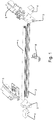
- Fig. 1 is merely to illustrate a prior art solution that may be replaced by the present invention.
- the prior art solution consists of a tubular sealing gasket 1 attached to an aluminium support rail 2.
- the support rail 2 is attached to a top cover (not shown) by means of a bracket 6.
- foam blocks (3, 6) are attached to provide sealing between the top cover and the sash profile.
- a polymer element 5 is provided at each end to provide support for the foam blocks and contribute to other attachment capabilities.
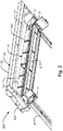
- Fig. 2 schematically depicts an embodiment of the top member ar-rangement 200 in a mounted position.
- An interface module 11 is mounted inside a top cover 20.
- the interface module 11 extends from one end of the top cover 20 to the other and abuts a sash profile 30 forming part of a sash of a window.
- Further elements of the interface module 11 that can be seen are a rib element 12 in the form of two parallel blades extending between a resilient corner element 13 positioned at an end part (clearly seen in fig. 3 ) of the interface module 11.
- a stiffening member 14 in the form of a strip 141 extending from one end part to the other and additionally attached to the rib element 12 at spaced apart points by means of integrally moulded connecting elements 142.
- the interface module is moulded in one piece in a thermoplastic elastomer.
- the rib element 12 may be in another shape, such as a solid or hollow elongate rectangular or triangular element, or other imaginable shapes.
- the strip 141 of the stiffening member 14 may be attached along the full length of the rib element 12 or attached at one or more points to an elongate base part (not shown).
- the top cover 20 and sash profile 30 are made of metal, preferably aluminium, but may also be made of plastic.
- Fig. 2 further discloses a mounting bracket 47 at each end of the top cover 20 for attaching the top cover 20 and the other elements of the top member ar-rangement, preferably to a window frame. Additionally an insulation pad 21 is disclosed at the top of the top cover 20.
- Fig. 3 schematically depicts an embodiment of the interface module 11 as seen in perspective from above.
- the interface module 11 comprises a number of climate regulating devices including a first 15a, second 15b and third 15c lip extending diverging, or in a fan like configuration, from the elongate base part (see fig. 4 ) directly below the three lips.
- the first 15a and the third 15c lip appear more flexible as they are wider, i.e. from a distal top end to the base part, than the second lip 15b.
- the second lip 15b is attached to the end part 50 at each end, whereas the first 15a and third 15c lip are only attached to the elongate base part. This way it is easier for the first and third lip to abut the sash profile.
- fig. 4 is an embodiment of a cross section of the interface module.
- the attachment of the lips 15a-c to the end part 50 may be configured in a different way, such that the first 15a and/or third lip 15c is/are attached to the end part and the second lip 15b only being attached to the elongate base part 16.
- a solid rectangular element 121a attached to the elongate base part 16 and at each end to the end parts 50.
- a fourth lip 122 is attached to the end part 50 and to the elongate base part 16.
- the fourth lip 122 serves as a holding means for an air filter (see fig. 6 ).
- Each end part comprises a number of different climate regulating devices.
- One of these devices is a wedged shaped guide element 51 adapted to engage with a recess of the sash profile and guide the interface module to the correct position during mounting.
- fig. 7 it can be seen how the wedged shaped guide element 51 fits perfectly with a recess in the cladding 31 on a window frame.
- the window frame may not be provided with cladding, but it may merely fit with the external surface of the frame in order to provide easy installation as well as regulating/preventing air flow from the outside in.
- the strip 141 of the stiffening member 14 and the connecting elements 142 are adapted for sealing engagement with the top cover 20.
- the connecting elements 142 are adapted to sealing engagement with the front 24 of the top cover.
- the strip 141 is adapted for sealing engagement with the bottom 26 of the top cover.
- the strip 141 is adapted to fit in a recess 27 of the bottom 26 of the top cover.
- the end part 50 comprises another climate regulating device, namely a resilient element 52 in the shape of a rectangular, oblique pyramid, the apex of which abuts the wedged shaped guide element 51 and the end of the second lip 15b.
- the resilient element 52 is adapted to sealing engagement with a corner of the sash profile.
- the resilient element may have other shapes, but preferably the resilient element is adapted to the shape of the sash profile such that it is substantially weather tight.
- a view at fig. 6 reveals how the resilient element 52 may fit together with the sash profile 30.
- the end part 50 comprises further climate regulating devices namely a first blade 53 and a second blade 54 positioned essentially in parallel to the first blade, the first blade 53 and the second blade 54 comprise a first edge 55 and a second edge 56 positioned at a distal end.
- the first edge 55 is adapted to sealing engagement with a top cover of a roof window and the second edge 56 is adapted to sealing engagement with the sash profile.
- the first 53 and the second 54 blade are attached to the wedged shaped guide element 51.
- the guide element may have other shapes.
- fig. 7 it can be seen how the second blade 54 seals the space above the cladding of the sash and the top cover.
- the first edge 55 of the first blade 53 is provided with a recess 57 for accommodating a cord, for example for a sensor.
- a temperature sensor or a rain sensor may be accommodated on the outside of the window, while the control parts are positioned on the inside of the window.
- the window may be controlled to close when it starts to rain.
- the recess 57 also constitute a climate regulating device as it enables the blades 53, 54 to seal tightly even though a cable is provided between the interfaces of the blade(s) and the sash.
- the end part 50 further comprises a wedged and/or hook shaped attachment member 58.
- the attachment member 58 is adapted to engage with a mounting bracket connected to the frame of the window. It may function as a temporary attachment feature, until the top cover arrangement is fixed to the window frame with more permanent means such as screws.
- the top member arrangement may also be attached by means of a male and a female part. One arranged on the top member arrangement and the other on the window frame and adapted for mutual snap locking engagement. The attachment member and/or snap locking engagement is fast and easy to use and secures a proper placement.
- the end part 50 further comprises a base member 59, to which all the parts on the end part are connected to, but the end part may be configured in a different way.
- Fig. 6 shows a cross section of a top member arrangement in an assembled state.
- An air filter 60 is here placed between the top cover 20 and the fourth lip 122.
- the air filter 60 preferably extends along the length of the interface module 11 from end part to end part.
- the top member arrangement 200 abuts an external face 49 of the top member of the frame 40.
- Fig. 7 shows an embodiment of an interface between a top cover 20, an interface module 11 and the cladding 31.
- the rib element 121b is here in a slightly different embodiment. Instead of being a solid rectangular element, two lips are provided extending perpendicular from the elongate base part 16.
- the top cover 20 comprises a top 22, a left and a right side 23a, 23b, respectively, and a front 24 and a back 25.
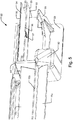
- Fig. 8 shows an embodiment of a window 32 comprising a pane 33 defining plane, a frame 40 having a top member 41, a bottom member 42 and two side members 43, 44 defining a frame plane 45, and a sash 30 having a top member 34, a bottom member 35 and two side members 36, 37 defining a sash plane 46.
- the window is centre-hung in that the sash 30 is connected to the frame 40 by a pivot hinge provided between side members 36, 43; 37, 44 of the frame 40 and sash 30, respectively, to be openable by tilting the sash 30 of the window 32 about the pivot hinge axis 38 defined by the pivot hinge.
- the sash 30 is provided with a cladding 39
- the frame 40 is likewise provided with a cladding 31, preferably in aluminium or other weatherproof material.
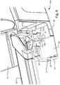
- Fig. 9 shows an embodiment of the top member arrangement 200 in an assembled state according to the present invention.
- the hook shaped head of the attachment member 58 engages with the mounting bracket 47 for attachment to the frame (not shown).
- the stiffness may be obtained in different ways for example by using rib elements in a different shapes /sizes or using a different material that provides a more stiff structure of the interface module.
- end parts are preferably similar, they may be different from each other.
Landscapes
- Engineering & Computer Science (AREA)
- Civil Engineering (AREA)
- Structural Engineering (AREA)
- Architecture (AREA)
- Specific Sealing Or Ventilating Devices For Doors And Windows (AREA)
- Roof Covering Using Slabs Or Stiff Sheets (AREA)
Claims (14)
- Agencement d'organe de sommet (200) pour une fenêtre de toit (32) comprenant :un module d'interface (11) comprenant au moins un dispositif régulateur de climat incluant une première (15a), une deuxième (15b) et une troisième (15c) lèvre ayant chacune un sommet libre distal et une extrémité basse, lesquelles lèvres s'étendent suivant la longueur d'une partie de base allongée (16) et avec les sommets libres distaux s'étendant en s'écartant de la partie de base allongée (16),dans lequel un côté interne de la première (15a) et de la troisième (15c) lèvre, respectivement, est adapté à une mise en prise étanche avec un profilé de châssis (30) de la fenêtre de toit (32) dans une position fermée, caractérisé en ce quele module d'interface (11) comprend en outre une partie d'extrémité (50) ménagée en l'une ou les deux extrémités de la partie de base allongée (16), qui est/sont formées solidairement avec la partie de base allongée (16) et la première (15a), la deuxième (15b) et la troisième (15c) lèvre, le module d'interface (11) étant ainsi constitué d'un seul tenant.
- Agencement d'organe de sommet (200) selon la revendication 1, dans lequel la deuxième lèvre (15b) est positionnée entre la première (15a) et la troisième (15c) lèvre et un bord de la deuxième lèvre (15b) au niveau de son sommet libre distal est de préférence adapté à une mise en prise étanche avec le profilé de châssis (30).
- Agencement d'organe de sommet (200) selon la revendication 1 ou 2, dans lequel la partie d'extrémité du module comprend un élément résilient (52), de préférence sous la forme d'une pyramide oblique sensiblement rectangulaire, adapté à une mise en prise étanche avec un coin du profilé de châssis (30).
- Agencement d'organe de sommet (200) selon l'une quelconque des revendications précédentes, dans lequel le module d'interface (11) comprend en outre un élément de nervure (12) fixé à et s'étendant suivant la longueur de la partie de base allongée (16), l'élément de nervure (12) étant adapté pour conférer une rigidité à la partie de base allongée (16).
- Agencement d'organe de sommet (200) selon l'une quelconque des revendications précédentes, dans lequel la deuxième lèvre (15b) est plus rigide que la première (15a) et/ou la troisième (15c) lèvre.
- Agencement d'organe de sommet (200) selon l'une quelconque des revendications précédentes, comprenant en outre un organe raidisseur (14) qui est fixé à la (aux) partie(s) d'extrémité (50) et qui est positionné parallèlement à et à l'écart de la partie de base allongée (16).
- Agencement d'organe de sommet (200) selon l'une quelconque des revendications précédentes, dans lequel la (les) partie(s) d'extrémité (50) comprend (comprennent) un élément guide en forme de cale (51) adapté pour se mettre en prise avec un évidement (57) du profilé de châssis (30) et guider le module d'interface (11) vers la position correcte pendant le montage.
- Agencement d'organe de sommet (200) selon l'une quelconque des revendications précédentes, dans lequel la partie d'extrémité (50) comprend une première lame (53), et de préférence une seconde lame (54) positionnée essentiellement parallèlement à la première lame (53),
la première lame (53), et de préférence la seconde lame (54), comprend(comprennent) un premier (55) et un second (56) bord, dans lequel le premier bord (55) est adapté à une mise en prise étanche avec un cache-sommet (20) de la fenêtre de toit (32) et le second bord (56) est adapté à une mise en prise étanche avec le profilé de châssis (30). - Agencement d'organe de sommet (200) selon la revendication 8, dans lequel le premier bord (55) de la première lame (53) est pourvu d'un évidement (57) pour accueillir une corde, par exemple pour un capteur.
- Agencement d'organe de sommet (200) selon l'une quelconque des revendications précédentes, dans lequel le module d'interface (11) est constitué d'un élastomère thermoplastique, TPE, ou d'un vulcanisat thermoplastique, TPV.
- Agencement d'organe de sommet (200) selon l'une quelconque des revendications précédentes, dans lequel le module d'interface (11) est moulé d'un seul tenant au moyen d'une injection à répétition.
- Agencement d'organe de sommet (200) selon l'une quelconque des revendications 1 à 11, comprenant un cache-sommet (20) et un filtre à air (60).
- Fenêtre de toit (32) comprenant un châssis (30) et un cadre (40), le cadre (40) comprenant un organe de cadre de sommet (41), un organe de cadre de base (42), deux organes de cadre de côté (43, 44), et un agencement d'organe de sommet (200) selon l'une quelconque des revendications 1 à 12, dans lequel l'agencement d'organe de sommet (200) est adapté pour être positionné au niveau d'une face externe de l'organe de cadre de sommet (41).
- Procédé d'assemblage d'une fenêtre de toit (32) comprenant les étapes de raccordement d'un cadre (40) avec un organe de sommet (41), un organe de base (42) et deux organes de côté (43, 44) définissant un plan de cadre (45), avec un châssis (30) ayant un organe de sommet (41), un organe de base (42) et deux organes de côté (43, 44) définissant un plan de châssis (46), le châssis (30) étant raccordé au cadre (40) par une charnière à pivot ménagée entre les organes de côté (36, 43 ; 37, 44) du cadre (40) et du châssis (30), respectivement,
le raccordement d'un agencement d'organe de sommet (200) selon l'une quelconque des revendications 1 à 12 au cadre par au moins deux supports de montage (47), et
la mise en prise des supports de montage (47) avec au moins deux organes de fixation qui sont formés solidairement avec un module d'interface (11) de l'agencement d'organe de sommet (200).
Priority Applications (2)
| Application Number | Priority Date | Filing Date | Title |
|---|---|---|---|
| EP18201192.4A EP3502405B1 (fr) | 2014-12-02 | 2015-12-02 | Agencement d'élément supérieur pour une fenêtre de toit |
| PL15804311T PL3227516T3 (pl) | 2014-12-02 | 2015-12-02 | Układ członów górnych do okna dachowego |
Applications Claiming Priority (2)
| Application Number | Priority Date | Filing Date | Title |
|---|---|---|---|
| DK201470755A DK178424B1 (en) | 2014-12-02 | 2014-12-02 | Top member arrangement for a roof window |
| PCT/DK2015/050375 WO2016086943A1 (fr) | 2014-12-02 | 2015-12-02 | Agencement d'élément supérieur pour une fenêtre de toit |
Related Child Applications (1)
| Application Number | Title | Priority Date | Filing Date |
|---|---|---|---|
| EP18201192.4A Division EP3502405B1 (fr) | 2014-12-02 | 2015-12-02 | Agencement d'élément supérieur pour une fenêtre de toit |
Publications (2)
| Publication Number | Publication Date |
|---|---|
| EP3227516A1 EP3227516A1 (fr) | 2017-10-11 |
| EP3227516B1 true EP3227516B1 (fr) | 2018-10-24 |
Family
ID=54780033
Family Applications (2)
| Application Number | Title | Priority Date | Filing Date |
|---|---|---|---|
| EP15804311.7A Active EP3227516B1 (fr) | 2014-12-02 | 2015-12-02 | Agencement d'élément supérieur pour une fenêtre de toit |
| EP18201192.4A Active EP3502405B1 (fr) | 2014-12-02 | 2015-12-02 | Agencement d'élément supérieur pour une fenêtre de toit |
Family Applications After (1)
| Application Number | Title | Priority Date | Filing Date |
|---|---|---|---|
| EP18201192.4A Active EP3502405B1 (fr) | 2014-12-02 | 2015-12-02 | Agencement d'élément supérieur pour une fenêtre de toit |
Country Status (5)
| Country | Link |
|---|---|
| EP (2) | EP3227516B1 (fr) |
| CN (1) | CN107002456B (fr) |
| DK (1) | DK178424B1 (fr) |
| PL (2) | PL3227516T3 (fr) |
| WO (1) | WO2016086943A1 (fr) |
Family Cites Families (7)
| Publication number | Priority date | Publication date | Assignee | Title |
|---|---|---|---|---|
| GB2388399B (en) * | 2001-01-19 | 2004-10-06 | Vkr Holding As | A roof window assembly and components |
| US20050000173A1 (en) * | 2003-07-02 | 2005-01-06 | Vkr Holding A/S | Skylight with sealing gasket |
| PL217419B1 (pl) * | 2007-04-27 | 2014-07-31 | Fakro Pp Spółka Z Ograniczoną Odpowiedzialnością | Okno dachowe z kanałem nawiewu powietrza |
| DE102007036278A1 (de) * | 2007-07-31 | 2009-02-05 | Klaus Becker | Veluxfenster |
| CN102812198B (zh) * | 2010-03-19 | 2015-08-05 | 宁波市鄞州松井工贸有限公司 | 用于窗的通风系统 |
| DK180106B1 (en) * | 2012-01-13 | 2020-05-05 | Vkr Holding A/S | A window having interchangeable interface means and a method of providing a window |
| GB201209262D0 (en) * | 2012-05-25 | 2012-07-04 | Keystone Lintels Ltd | A hood assembly arrangement for a roof window |
-
2014
- 2014-12-02 DK DK201470755A patent/DK178424B1/en active
-
2015
- 2015-12-02 EP EP15804311.7A patent/EP3227516B1/fr active Active
- 2015-12-02 WO PCT/DK2015/050375 patent/WO2016086943A1/fr not_active Ceased
- 2015-12-02 EP EP18201192.4A patent/EP3502405B1/fr active Active
- 2015-12-02 PL PL15804311T patent/PL3227516T3/pl unknown
- 2015-12-02 CN CN201580065076.5A patent/CN107002456B/zh active Active
- 2015-12-02 PL PL18201192.4T patent/PL3502405T3/pl unknown
Non-Patent Citations (1)
| Title |
|---|
| None * |
Also Published As
| Publication number | Publication date |
|---|---|
| CN107002456A (zh) | 2017-08-01 |
| EP3502405A2 (fr) | 2019-06-26 |
| PL3502405T3 (pl) | 2024-06-10 |
| EP3502405B1 (fr) | 2024-03-06 |
| WO2016086943A1 (fr) | 2016-06-09 |
| EP3502405A3 (fr) | 2019-11-13 |
| DK178424B1 (en) | 2016-02-22 |
| EP3227516A1 (fr) | 2017-10-11 |
| PL3227516T3 (pl) | 2019-03-29 |
| CN107002456B (zh) | 2018-10-12 |
Similar Documents
| Publication | Publication Date | Title |
|---|---|---|
| US8966839B2 (en) | Window assembly | |
| EP3396100A1 (fr) | Fenêtre de toit plat avec couverture extérieure | |
| US10213905B2 (en) | Architectural panel assembly and tools | |
| US5086604A (en) | Mounting for storm windows | |
| US8904720B2 (en) | Mullion cover linkage | |
| US8959851B1 (en) | Manufactures, methods and structures to reduce energy transfer in buildings | |
| US9776490B2 (en) | Window module | |
| KR101092718B1 (ko) | 자동 유리 닦는 미서기창 | |
| CN108138494A (zh) | 天窗安装系统及组件 | |
| EP3227516B1 (fr) | Agencement d'élément supérieur pour une fenêtre de toit | |
| US8673424B2 (en) | Snap in weatherstripping | |
| EP2171170B1 (fr) | Système pour adapter des stores vénitiens à un toit de jardin d'hiver | |
| US20130212946A1 (en) | Louver assembly | |
| HUP0004537A2 (hu) | Eresztartó | |
| ES2791309T3 (es) | Listón cobertor para colocar en un componente, así como método para colocar un listón cobertor de este tipo en un componente | |
| EP2105567A1 (fr) | Ensemble formant fenêtre avec ensemble de panneaux de couverture pour couvrir l'ouverture de la fenêtre | |
| KR20150100418A (ko) | 차양막용 빗물가리개 | |
| KR101448398B1 (ko) | 프로젝트창 | |
| US9475375B1 (en) | Weather strip foam retention feature | |
| EP2058449A2 (fr) | Ensemble de montage pour couverture de toit | |
| EP2982811B1 (fr) | Barrière de vapeur pour une fenêtre de toit | |
| JP2006088928A (ja) | ドアインナーシール | |
| EP3049586B1 (fr) | Système de joint | |
| AU2014101416A4 (en) | Shutter and Profile for a Frame of a Shutter | |
| KR20180029574A (ko) | 평레일 창호 |
Legal Events
| Date | Code | Title | Description |
|---|---|---|---|
| STAA | Information on the status of an ep patent application or granted ep patent |
Free format text: STATUS: THE INTERNATIONAL PUBLICATION HAS BEEN MADE |
|
| PUAI | Public reference made under article 153(3) epc to a published international application that has entered the european phase |
Free format text: ORIGINAL CODE: 0009012 |
|
| STAA | Information on the status of an ep patent application or granted ep patent |
Free format text: STATUS: REQUEST FOR EXAMINATION WAS MADE |
|
| 17P | Request for examination filed |
Effective date: 20170621 |
|
| AK | Designated contracting states |
Kind code of ref document: A1 Designated state(s): AL AT BE BG CH CY CZ DE DK EE ES FI FR GB GR HR HU IE IS IT LI LT LU LV MC MK MT NL NO PL PT RO RS SE SI SK SM TR |
|
| AX | Request for extension of the european patent |
Extension state: BA ME |
|
| DAV | Request for validation of the european patent (deleted) | ||
| DAX | Request for extension of the european patent (deleted) | ||
| REG | Reference to a national code |
Ref country code: DE Ref legal event code: R079 Ref document number: 602015018831 Country of ref document: DE Free format text: PREVIOUS MAIN CLASS: E06B0007100000 Ipc: E04D0013030000 |
|
| GRAP | Despatch of communication of intention to grant a patent |
Free format text: ORIGINAL CODE: EPIDOSNIGR1 |
|
| STAA | Information on the status of an ep patent application or granted ep patent |
Free format text: STATUS: GRANT OF PATENT IS INTENDED |
|
| RIC1 | Information provided on ipc code assigned before grant |
Ipc: E06B 7/23 20060101ALI20180601BHEP Ipc: E04D 13/03 20060101AFI20180601BHEP Ipc: E06B 7/10 20060101ALI20180601BHEP |
|
| INTG | Intention to grant announced |
Effective date: 20180621 |
|
| GRAS | Grant fee paid |
Free format text: ORIGINAL CODE: EPIDOSNIGR3 |
|
| GRAA | (expected) grant |
Free format text: ORIGINAL CODE: 0009210 |
|
| STAA | Information on the status of an ep patent application or granted ep patent |
Free format text: STATUS: THE PATENT HAS BEEN GRANTED |
|
| AK | Designated contracting states |
Kind code of ref document: B1 Designated state(s): AL AT BE BG CH CY CZ DE DK EE ES FI FR GB GR HR HU IE IS IT LI LT LU LV MC MK MT NL NO PL PT RO RS SE SI SK SM TR |
|
| REG | Reference to a national code |
Ref country code: CH Ref legal event code: EP |
|
| REG | Reference to a national code |
Ref country code: IE Ref legal event code: FG4D |
|
| REG | Reference to a national code |
Ref country code: AT Ref legal event code: REF Ref document number: 1056837 Country of ref document: AT Kind code of ref document: T Effective date: 20181115 |
|
| REG | Reference to a national code |
Ref country code: DE Ref legal event code: R096 Ref document number: 602015018831 Country of ref document: DE |
|
| REG | Reference to a national code |
Ref country code: NL Ref legal event code: FP |
|
| REG | Reference to a national code |
Ref country code: LT Ref legal event code: MG4D |
|
| PG25 | Lapsed in a contracting state [announced via postgrant information from national office to epo] |
Ref country code: IS Free format text: LAPSE BECAUSE OF FAILURE TO SUBMIT A TRANSLATION OF THE DESCRIPTION OR TO PAY THE FEE WITHIN THE PRESCRIBED TIME-LIMIT Effective date: 20190224 Ref country code: BG Free format text: LAPSE BECAUSE OF FAILURE TO SUBMIT A TRANSLATION OF THE DESCRIPTION OR TO PAY THE FEE WITHIN THE PRESCRIBED TIME-LIMIT Effective date: 20190124 Ref country code: NO Free format text: LAPSE BECAUSE OF FAILURE TO SUBMIT A TRANSLATION OF THE DESCRIPTION OR TO PAY THE FEE WITHIN THE PRESCRIBED TIME-LIMIT Effective date: 20190124 Ref country code: LT Free format text: LAPSE BECAUSE OF FAILURE TO SUBMIT A TRANSLATION OF THE DESCRIPTION OR TO PAY THE FEE WITHIN THE PRESCRIBED TIME-LIMIT Effective date: 20181024 Ref country code: LV Free format text: LAPSE BECAUSE OF FAILURE TO SUBMIT A TRANSLATION OF THE DESCRIPTION OR TO PAY THE FEE WITHIN THE PRESCRIBED TIME-LIMIT Effective date: 20181024 Ref country code: HR Free format text: LAPSE BECAUSE OF FAILURE TO SUBMIT A TRANSLATION OF THE DESCRIPTION OR TO PAY THE FEE WITHIN THE PRESCRIBED TIME-LIMIT Effective date: 20181024 Ref country code: FI Free format text: LAPSE BECAUSE OF FAILURE TO SUBMIT A TRANSLATION OF THE DESCRIPTION OR TO PAY THE FEE WITHIN THE PRESCRIBED TIME-LIMIT Effective date: 20181024 |
|
| PG25 | Lapsed in a contracting state [announced via postgrant information from national office to epo] |
Ref country code: PT Free format text: LAPSE BECAUSE OF FAILURE TO SUBMIT A TRANSLATION OF THE DESCRIPTION OR TO PAY THE FEE WITHIN THE PRESCRIBED TIME-LIMIT Effective date: 20190224 Ref country code: SE Free format text: LAPSE BECAUSE OF FAILURE TO SUBMIT A TRANSLATION OF THE DESCRIPTION OR TO PAY THE FEE WITHIN THE PRESCRIBED TIME-LIMIT Effective date: 20181024 Ref country code: AL Free format text: LAPSE BECAUSE OF FAILURE TO SUBMIT A TRANSLATION OF THE DESCRIPTION OR TO PAY THE FEE WITHIN THE PRESCRIBED TIME-LIMIT Effective date: 20181024 Ref country code: GR Free format text: LAPSE BECAUSE OF FAILURE TO SUBMIT A TRANSLATION OF THE DESCRIPTION OR TO PAY THE FEE WITHIN THE PRESCRIBED TIME-LIMIT Effective date: 20190125 Ref country code: RS Free format text: LAPSE BECAUSE OF FAILURE TO SUBMIT A TRANSLATION OF THE DESCRIPTION OR TO PAY THE FEE WITHIN THE PRESCRIBED TIME-LIMIT Effective date: 20181024 |
|
| REG | Reference to a national code |
Ref country code: DE Ref legal event code: R097 Ref document number: 602015018831 Country of ref document: DE |
|
| PG25 | Lapsed in a contracting state [announced via postgrant information from national office to epo] |
Ref country code: DK Free format text: LAPSE BECAUSE OF FAILURE TO SUBMIT A TRANSLATION OF THE DESCRIPTION OR TO PAY THE FEE WITHIN THE PRESCRIBED TIME-LIMIT Effective date: 20181024 Ref country code: ES Free format text: LAPSE BECAUSE OF FAILURE TO SUBMIT A TRANSLATION OF THE DESCRIPTION OR TO PAY THE FEE WITHIN THE PRESCRIBED TIME-LIMIT Effective date: 20181024 |
|
| REG | Reference to a national code |
Ref country code: CH Ref legal event code: PL |
|
| PG25 | Lapsed in a contracting state [announced via postgrant information from national office to epo] |
Ref country code: EE Free format text: LAPSE BECAUSE OF FAILURE TO SUBMIT A TRANSLATION OF THE DESCRIPTION OR TO PAY THE FEE WITHIN THE PRESCRIBED TIME-LIMIT Effective date: 20181024 Ref country code: LU Free format text: LAPSE BECAUSE OF NON-PAYMENT OF DUE FEES Effective date: 20181202 Ref country code: RO Free format text: LAPSE BECAUSE OF FAILURE TO SUBMIT A TRANSLATION OF THE DESCRIPTION OR TO PAY THE FEE WITHIN THE PRESCRIBED TIME-LIMIT Effective date: 20181024 Ref country code: SK Free format text: LAPSE BECAUSE OF FAILURE TO SUBMIT A TRANSLATION OF THE DESCRIPTION OR TO PAY THE FEE WITHIN THE PRESCRIBED TIME-LIMIT Effective date: 20181024 Ref country code: MC Free format text: LAPSE BECAUSE OF FAILURE TO SUBMIT A TRANSLATION OF THE DESCRIPTION OR TO PAY THE FEE WITHIN THE PRESCRIBED TIME-LIMIT Effective date: 20181024 Ref country code: SM Free format text: LAPSE BECAUSE OF FAILURE TO SUBMIT A TRANSLATION OF THE DESCRIPTION OR TO PAY THE FEE WITHIN THE PRESCRIBED TIME-LIMIT Effective date: 20181024 |
|
| PLBE | No opposition filed within time limit |
Free format text: ORIGINAL CODE: 0009261 |
|
| STAA | Information on the status of an ep patent application or granted ep patent |
Free format text: STATUS: NO OPPOSITION FILED WITHIN TIME LIMIT |
|
| REG | Reference to a national code |
Ref country code: IE Ref legal event code: MM4A |
|
| 26N | No opposition filed |
Effective date: 20190725 |
|
| REG | Reference to a national code |
Ref country code: BE Ref legal event code: MM Effective date: 20181231 |
|
| PG25 | Lapsed in a contracting state [announced via postgrant information from national office to epo] |
Ref country code: IE Free format text: LAPSE BECAUSE OF NON-PAYMENT OF DUE FEES Effective date: 20181202 Ref country code: SI Free format text: LAPSE BECAUSE OF FAILURE TO SUBMIT A TRANSLATION OF THE DESCRIPTION OR TO PAY THE FEE WITHIN THE PRESCRIBED TIME-LIMIT Effective date: 20181024 |
|
| PG25 | Lapsed in a contracting state [announced via postgrant information from national office to epo] |
Ref country code: BE Free format text: LAPSE BECAUSE OF NON-PAYMENT OF DUE FEES Effective date: 20181231 |
|
| PG25 | Lapsed in a contracting state [announced via postgrant information from national office to epo] |
Ref country code: CH Free format text: LAPSE BECAUSE OF NON-PAYMENT OF DUE FEES Effective date: 20181231 Ref country code: LI Free format text: LAPSE BECAUSE OF NON-PAYMENT OF DUE FEES Effective date: 20181231 |
|
| PG25 | Lapsed in a contracting state [announced via postgrant information from national office to epo] |
Ref country code: MT Free format text: LAPSE BECAUSE OF NON-PAYMENT OF DUE FEES Effective date: 20181202 |
|
| PG25 | Lapsed in a contracting state [announced via postgrant information from national office to epo] |
Ref country code: TR Free format text: LAPSE BECAUSE OF FAILURE TO SUBMIT A TRANSLATION OF THE DESCRIPTION OR TO PAY THE FEE WITHIN THE PRESCRIBED TIME-LIMIT Effective date: 20181024 |
|
| PG25 | Lapsed in a contracting state [announced via postgrant information from national office to epo] |
Ref country code: MK Free format text: LAPSE BECAUSE OF NON-PAYMENT OF DUE FEES Effective date: 20181024 Ref country code: CY Free format text: LAPSE BECAUSE OF FAILURE TO SUBMIT A TRANSLATION OF THE DESCRIPTION OR TO PAY THE FEE WITHIN THE PRESCRIBED TIME-LIMIT Effective date: 20181024 |
|
| REG | Reference to a national code |
Ref country code: AT Ref legal event code: UEP Ref document number: 1056837 Country of ref document: AT Kind code of ref document: T Effective date: 20181024 |
|
| PGFP | Annual fee paid to national office [announced via postgrant information from national office to epo] |
Ref country code: NL Payment date: 20251112 Year of fee payment: 11 |
|
| PGFP | Annual fee paid to national office [announced via postgrant information from national office to epo] |
Ref country code: DE Payment date: 20251104 Year of fee payment: 11 |
|
| PGFP | Annual fee paid to national office [announced via postgrant information from national office to epo] |
Ref country code: GB Payment date: 20251114 Year of fee payment: 11 |
|
| PGFP | Annual fee paid to national office [announced via postgrant information from national office to epo] |
Ref country code: AT Payment date: 20251126 Year of fee payment: 11 |
|
| PGFP | Annual fee paid to national office [announced via postgrant information from national office to epo] |
Ref country code: IT Payment date: 20251121 Year of fee payment: 11 |
|
| PGFP | Annual fee paid to national office [announced via postgrant information from national office to epo] |
Ref country code: HU Payment date: 20251127 Year of fee payment: 11 Ref country code: FR Payment date: 20251124 Year of fee payment: 11 |
|
| PGFP | Annual fee paid to national office [announced via postgrant information from national office to epo] |
Ref country code: CZ Payment date: 20251128 Year of fee payment: 11 |
|
| PGFP | Annual fee paid to national office [announced via postgrant information from national office to epo] |
Ref country code: PL Payment date: 20251117 Year of fee payment: 11 |