EP3227542B1 - Procédé de commande d'un fonctionnement d'un système de soupape d'admission variable d'un moteur à pistons à combustion interne, et moteur à pistons à combustion interne - Google Patents
Procédé de commande d'un fonctionnement d'un système de soupape d'admission variable d'un moteur à pistons à combustion interne, et moteur à pistons à combustion interne Download PDFInfo
- Publication number
- EP3227542B1 EP3227542B1 EP14821225.1A EP14821225A EP3227542B1 EP 3227542 B1 EP3227542 B1 EP 3227542B1 EP 14821225 A EP14821225 A EP 14821225A EP 3227542 B1 EP3227542 B1 EP 3227542B1
- Authority
- EP
- European Patent Office
- Prior art keywords
- cylinder
- pressure
- estimated
- crank angle
- est
- Prior art date
- Legal status (The legal status is an assumption and is not a legal conclusion. Google has not performed a legal analysis and makes no representation as to the accuracy of the status listed.)
- Active
Links
Images


Classifications
-
- F—MECHANICAL ENGINEERING; LIGHTING; HEATING; WEAPONS; BLASTING
- F02—COMBUSTION ENGINES; HOT-GAS OR COMBUSTION-PRODUCT ENGINE PLANTS
- F02D—CONTROLLING COMBUSTION ENGINES
- F02D41/00—Electrical control of supply of combustible mixture or its constituents
- F02D41/008—Controlling each cylinder individually
- F02D41/0085—Balancing of cylinder outputs, e.g. speed, torque or air-fuel ratio
-
- F—MECHANICAL ENGINEERING; LIGHTING; HEATING; WEAPONS; BLASTING
- F02—COMBUSTION ENGINES; HOT-GAS OR COMBUSTION-PRODUCT ENGINE PLANTS
- F02D—CONTROLLING COMBUSTION ENGINES
- F02D35/00—Controlling engines, dependent on conditions exterior or interior to engines, not otherwise provided for
- F02D35/02—Controlling engines, dependent on conditions exterior or interior to engines, not otherwise provided for on interior conditions
- F02D35/023—Controlling engines, dependent on conditions exterior or interior to engines, not otherwise provided for on interior conditions by determining the cylinder pressure
-
- F—MECHANICAL ENGINEERING; LIGHTING; HEATING; WEAPONS; BLASTING
- F02—COMBUSTION ENGINES; HOT-GAS OR COMBUSTION-PRODUCT ENGINE PLANTS
- F02D—CONTROLLING COMBUSTION ENGINES
- F02D13/00—Controlling the engine output power by varying inlet or exhaust valve operating characteristics, e.g. timing
- F02D13/02—Controlling the engine output power by varying inlet or exhaust valve operating characteristics, e.g. timing during engine operation
- F02D13/0223—Variable control of the intake valves only
- F02D13/0234—Variable control of the intake valves only changing the valve timing only
-
- F—MECHANICAL ENGINEERING; LIGHTING; HEATING; WEAPONS; BLASTING
- F02—COMBUSTION ENGINES; HOT-GAS OR COMBUSTION-PRODUCT ENGINE PLANTS
- F02D—CONTROLLING COMBUSTION ENGINES
- F02D35/00—Controlling engines, dependent on conditions exterior or interior to engines, not otherwise provided for
- F02D35/02—Controlling engines, dependent on conditions exterior or interior to engines, not otherwise provided for on interior conditions
- F02D35/023—Controlling engines, dependent on conditions exterior or interior to engines, not otherwise provided for on interior conditions by determining the cylinder pressure
- F02D35/024—Controlling engines, dependent on conditions exterior or interior to engines, not otherwise provided for on interior conditions by determining the cylinder pressure using an estimation
-
- F—MECHANICAL ENGINEERING; LIGHTING; HEATING; WEAPONS; BLASTING
- F02—COMBUSTION ENGINES; HOT-GAS OR COMBUSTION-PRODUCT ENGINE PLANTS
- F02D—CONTROLLING COMBUSTION ENGINES
- F02D41/00—Electrical control of supply of combustible mixture or its constituents
- F02D41/0002—Controlling intake air
-
- F—MECHANICAL ENGINEERING; LIGHTING; HEATING; WEAPONS; BLASTING
- F02—COMBUSTION ENGINES; HOT-GAS OR COMBUSTION-PRODUCT ENGINE PLANTS
- F02D—CONTROLLING COMBUSTION ENGINES
- F02D13/00—Controlling the engine output power by varying inlet or exhaust valve operating characteristics, e.g. timing
- F02D13/02—Controlling the engine output power by varying inlet or exhaust valve operating characteristics, e.g. timing during engine operation
- F02D13/0269—Controlling the valves to perform a Miller-Atkinson cycle
-
- F—MECHANICAL ENGINEERING; LIGHTING; HEATING; WEAPONS; BLASTING
- F02—COMBUSTION ENGINES; HOT-GAS OR COMBUSTION-PRODUCT ENGINE PLANTS
- F02D—CONTROLLING COMBUSTION ENGINES
- F02D41/00—Electrical control of supply of combustible mixture or its constituents
- F02D41/0002—Controlling intake air
- F02D2041/001—Controlling intake air for engines with variable valve actuation
-
- Y—GENERAL TAGGING OF NEW TECHNOLOGICAL DEVELOPMENTS; GENERAL TAGGING OF CROSS-SECTIONAL TECHNOLOGIES SPANNING OVER SEVERAL SECTIONS OF THE IPC; TECHNICAL SUBJECTS COVERED BY FORMER USPC CROSS-REFERENCE ART COLLECTIONS [XRACs] AND DIGESTS
- Y02—TECHNOLOGIES OR APPLICATIONS FOR MITIGATION OR ADAPTATION AGAINST CLIMATE CHANGE
- Y02T—CLIMATE CHANGE MITIGATION TECHNOLOGIES RELATED TO TRANSPORTATION
- Y02T10/00—Road transport of goods or passengers
- Y02T10/10—Internal combustion engine [ICE] based vehicles
- Y02T10/12—Improving ICE efficiencies
-
- Y—GENERAL TAGGING OF NEW TECHNOLOGICAL DEVELOPMENTS; GENERAL TAGGING OF CROSS-SECTIONAL TECHNOLOGIES SPANNING OVER SEVERAL SECTIONS OF THE IPC; TECHNICAL SUBJECTS COVERED BY FORMER USPC CROSS-REFERENCE ART COLLECTIONS [XRACs] AND DIGESTS
- Y02—TECHNOLOGIES OR APPLICATIONS FOR MITIGATION OR ADAPTATION AGAINST CLIMATE CHANGE
- Y02T—CLIMATE CHANGE MITIGATION TECHNOLOGIES RELATED TO TRANSPORTATION
- Y02T10/00—Road transport of goods or passengers
- Y02T10/10—Internal combustion engine [ICE] based vehicles
- Y02T10/40—Engine management systems
Definitions
- the present invention relates to a method of controlling an operation of a variable inlet valve system of an internal combustion piston engine according to the preamble of claim 1.
- the present invention relates also to an internal combustion piston engine.
- US 20110171173 A1 discloses a system for and a method of balancing cylinders of an internal combustion piston engine.
- a maximum pressure and knock value and a mean maximum mean pressure of each cylinder is determined.
- the difference between the maximum pressure and the mean maximum pressure is determined.
- the differences are compared to a certain deviation range of the mean maximum pressure and the knock value to a certain knock limit value.
- the duration of the fuel injection of the cylinder is adjusted in case the difference of a single cylinder exceeds the lower limit of the deviation range and the knock value of the cylinder is less than the knock limit value or the difference of the cylinders exceeds the upper limit of deviation range.
- US 2008196488 A1 discloses a method and device for determining with the aid of a cylinder pressure sensor the ratio between the fuel mass burned in a cylinder of an internal combustion engine and the fuel mass supplied to the cylinder.
- WO 2008095569 A1 discloses a method of self-tuning cylinder pressure based heat release computation. The method comprises measuring a cylinder pressure as a function of crank angle and based on the measurement calculating a first polytropic exponent for a compression stroke and a second polytropic exponent for an expansion stroke. Then interpolation of the first and the second polytropic exponents and performing a net release computation based on the interpolated polytropic exponent.
- US 6 530361 B1 discloses a control of the compression pressure through the control of the inlet valve.
- EP 2570637 A2 discloses a device for controlling an internal combustion engine comprising a variable valve mechanism for varying opening areas or the working angles of at least either the intake valves or the exhaust valves, wherein a pressure in the cylinder is calculated based on the opening area or the working angle at least either the intake valve or the exhaust valve varied by the variable valve mechanism.
- An object of the invention is to provide a method for controlling an operation of a variable inlet valve system of an internal combustion piston engine in which the performance is improved compared to the prior art solutions.
- each cylinder of the engine comprises at least
- This provides a method of controlling an operation of an inlet valve system of an internal combustion piston engine in which performance is considerably improved. More specifically, the operation of the inlet valve system comprises advantageously adjusting the timing of the inlet valve closing.
- the timing means controlling the closing in respect to the crank angle, and thus also in respect to the position of the piston in the cylinder.
- the intake phase, the compression phase, the power phase, and the exhaust phase are practised successively during each cycle.
- the phases are cyclically repeated, thus the operation comprises a first cycle of phases, the second cycle of phases etc. wherein the first cycle is referred to as a preceding cycle and the second cycle is referred to as succeeding cycle.
- the steps of measuring cylinder pressure at each cylinder at least at a one predetermined crank angle position, determining an estimated polytropic index for each cylinder corresponding to the at least one measured cylinder pressure at the predetermined crank angle position, and determining an estimated compression pressure for at least at a second crank angle position by using the at least one measured cylinder pressure and the at least one estimated polytropic index are executed during a preceding cycle, and the step of controlling the operation of the inlet valve system in response to the estimated compression pressure is executed during a succeeding cycle.
- the steps i.-iii. are executed at least one cycle ahead than executing the step iv.
- the step of measuring cylinder pressure at least at a one predetermined crank angle position is executed during the compression phase.
- the step of measuring cylinder pressure ( p 0 ) at each cylinder at least at a one predetermined crank angle position ( ⁇ 0 ) is executed during the compression phase during a preceding cycle and the step of controlling the operation of the inlet valve system in a response to the estimated compression pressure ( p est ) is executed during a succeeding cycle.
- the steps ii.-iii. are executed during the compression phase before the piston reaches the top dead center position.
- the steps i.-iii. are executed in a preceding cycle, and the step iv. is executed during a succeeding cycle.
- the method comprises the step of using a predetermined value for the estimated polytropic index ( ⁇ ). In this case real-time estimation for the polytropic index ( ⁇ ) is not needed.
- the steps i.-iv. are repeated during the engine is running.
- the method comprises in step iv. to control the operation of the variable inlet valve system in each cylinder to obtaining a predetermined peak compression pressure in each cylinder.
- the aim is to obtain a same peak compression pressure in all cylinders and thus balancing the operation of cylinders so as to improve the performance of the engine.
- the estimated compression pressure is an estimated peak compression pressure and the operation of the variable inlet valve system is controlled by a response to the estimated peak compression pressure. Therefore, substantially the same peak compression pressure is obtained at each cylinder of the engine. This enhances the power output of the engine and improves the efficiency of the engine.
- the method comprises the step of comparing the estimated compression pressures of each cylinder and computing a mean value of compression pressures and using the mean value as the response for controlling the operation of the inlet valve system in step iv. in order to obtain a same peak compression pressure in each cylinder.
- the method comprises the step of controlling the operation of the inlet valve system by the response to the estimated compression pressure p est to obtain a predetermined target peak compression pressure.
- the predetermined target peak compression pressure may be decided in advance for each engine and engine load separately. It should be noted that the predetermined target peak compression pressure may be only a single number or it can be an adequate deviation range.
- the method comprises the step of controlling the operation of the inlet valve system of each cylinder by the response to the estimated compression pressure p est of each cylinder to obtain a same peak compression pressure in each cylinder.
- the method comprises the step of controlling the operation of the inlet valve system by the response to the estimated compression pressure p est that is the highest estimated compression pressure of the measured cylinder pressures so as to obtain a same peak compression pressure in each cylinder that is the highest estimated peak compression pressure.
- An internal combustion engine comprising
- the engine comprises more than one cylinder.
- control unit comprises instructions to operate the inlet valve system so as to obtain a pre-determined target compression pressure for each cylinder by controlling the closing timing of the valve system.
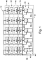
- Figure 1 depicts schematically a control system 10 arranged to execute instruction to practise a method of controlling operation of an inlet valve system 20 of an internal combustion piston engine 12.
- the engine 12 comprises generally several cylinders 30 into each of which a piston 32 is arranged to reciprocate inside the cylinder 30 between the top dead center and the bottom dead center.
- every cylinder 30.1,...,30.n includes one piston.
- the operation of one cylinder can be divided into four phases, whereas the engine may be a four stroke or two stroke engine: 1) intake phase, during which the combustion air is admitted to the cylinder, 2) compression phase wherein the piston moves towards its top dead center position and the pressure increases in the cylinder, 3) power phase wherein the expanding gas resulted from the fuel combustion forces the piston down the cylinder, and turning the crankshaft and the pressure in the cylinder decreases, and 4) exhaust phase for exhaust gas removal from the cylinder.
- the sequence of the phases from 1) to 4) is then repeated.
- variable inlet valve system 20 plays important role in the present invention. By controlling the inlet valve closing timings it is possible to control the pressure in the cylinder in advantageous manner.
- variable inlet valve system 20 comprises a first inlet valve system 20.1 that is arranged in connection with the first cylinder 30.1, a second inlet valve system 20.2 that is arranged in connection with the second cylinder 30.2, a third inlet valve system 20.3 that is arranged in connection with the third cylinder 30.3, a fourth inlet valve system 20.4 that is arranged in connection with the first cylinder 30.4 and an n th inlet valve system 20.n that is arranged in connection with the n th cylinder 30.n.
- Each of the inlet valve system is provided with operating system or mechanism by means of which the closing timing can be altered during the operation of the engine, and therefore the inlet valve system may be called here also as variable inlet valve system.
- the control system 10 of the engine 12 comprises a measuring unit 40 arranged to measure pressure p 0 in each of the cylinders 30.1,..,30.n during a compression phase before the piston 32 reaches a top dead center position at least at a one predetermined crank angle position ⁇ 0 , an estimation unit 50 arranged to determine an estimated polytropic index y corresponding to the measured cylinder pressure at the predetermined crank angle position ⁇ 0 , and a determination unit 60 arranged to determine an estimated compression pressure p est at a second crank angle position by using the measured cylinder pressure p 0 and the estimated polytropic index y, and the engine 12 further comprises a control unit 70 arranged to control the operation of the variable inlet valve system 20 in a response to the estimated compression pressure p est . Also the position of the crank angle is determined by a crank angle determination system 90, and the position is made available to the control system 10.
- the control system is adapted to operate the engine so that during a compression phase before the piston reaches the top dead center position, cylinder pressure of each cylinder 30.1, 30.2, 30.3, 30.4,..., 30.n is measured by the measurement unit 40, individually 40.1, 40.2, 40.3, 40.4,..., 40.n at least at a one predetermined crank angle position ⁇ 0 .
- Each cylinder 30.1, 30.2, 30.3, 30.4,..., 30.n is provided with pressure sensors 80.1, 80.2, 80.3, 80.4,...,80.n to measure the pressure in the cylinder.
- an estimated polytropic index y is determined by the estimation unit 50 with estimations 50.1, 50.2, 50.3, 50.4,..., 50.n for each cylinder based on the at least one measured cylinder pressure p 0 at the predetermined crank angle position ⁇ 0 .
- the polytropic index ⁇ is a real number and it can be estimated by any suitable conventional method such as disclosed in publication WO2008095569 A1 . So, the polytropic index ⁇ may be estimated e.g. in a following manner.
- the polytropic index ⁇ can also be a pre-determined value, and in that case real-time estimation for the polytropic index ⁇ is not needed.
- the estimated polytropic index is pre-determined, and such a pre-determined value for the polytropic index is used in the method.
- an estimated compression pressure p est at a second crank angle position ⁇ x can be determined at determination units 60.1, 60.2, 60.3, 60.4,..., 60.n for each cylinder.
- V TDC est is a volume of the cylinder at the top dead center position.
- variable inlet valve system 20.1, 20.2, 20.3, 20.4,..., 20.n is controlled by the control unit 70 comprising 70.1, 70.2, 70.3, 70.4,...,70.n for each cylinder 30.1, 30.2, 30.3, 30.4,...,30.n, respectively, based on the estimated compression pressure p est or p TDC est .
- the closing timing of the inlet valve system 20.1, 20.2, 20.3, 20.4,..., 20.n is controlled in such a way that the peak compression pressure is substantially the same for all cylinders. This balances the operation of each cylinder and the engine. In this connection the closing timing refers to the crank angle at which the inlet valve is closed.
- each of the cylinders operates substantially at a same pressure level.
- the charge air pressures are substantially the same at each cylinders.
- the cylinder pressure measurement is used to estimate the peak compression pressure and then the closing timing of the inlet valve system is controlled to get the same peak compression pressure for all cylinders.
- the pressure differences in cylinders are minimized.
- Another way to balance pressures in each cylinder 30.1, 30.2, 30.3, 30.4,...,30.n is to use one measured cylinder pressure as a reference. Then the measured pressure of first cylinder 20.1 is used to estimate the peak compression pressure that is used as a reference value for the rest of the cylinders 30.2, 30.3, 30.4,...,30.n.
- the operation of the rest of the inlet valve systems 70.2, 70.3, 70.4,...,70.n are controlled in such a way that in each cylinder the peak compression pressure will be substantially the same as the estimated peak compression pressure at the first cylinder 30.1.
- Figure 1 illustrates schematically that the measurement unit 40, the estimation units 50 and 60 and the control unit 70 are individual units. However, it should be understood that the measurement unit 40, the estimation units 50 and 60 and the control unit 70 may be arranged into a one physical unit that can be called e.g. as an adjustment unit that comprises instructions to measure, estimate and control in a previously described manner.
- Figure 2 shows schematically a diagram 100 of a method wherein the inlet valve system is controlled in a closed loop manner.
- the pressures in the cylinders 30 are measured 40, the polytropic indexes are determined 50, and estimated peak compression pressures in each cylinders are determined 60 during the compression phase.
- the control unit 70 is provided with a predetermined target peak compression pressure set point 110 and the operation in each cylinder is controlled with the control unit 70, such as a PID- control unit, by controlling the position of the variable inlet valve system 20 so that in each cylinder the peak compression pressure is substantially the same as the predetermined target peak compression pressure.
- the operation of the variable inlet valve system is controlled in such a way that each cylinder obtain the peak compression pressure within the pre-determined deviation range.
- the operation of the each inlet valve system 20.1,..., 20.n can be controlled independently so that each cylinder will obtain the predetermined target peak compression pressure. This stabilizes the pressure levels in the cylinders and give more power out from the engine. Therefore, the engine may operate at an optimal efficiency and the fuel is burned in the cylinders more efficiently.
- Figure 3 illustrates the operation of the present invention. It shows schematically a graph 200 with two curves for one cylinder: a one curve is an estimated compression pressure curve 222 and a second curve is a measured cylinder pressure curve 226. An estimated peak compression pressure 224 is shown in the estimated compression pressure curve 222. On the horizontal axis is the crank angle position ⁇ and on the vertical axis is the pressure p in the cylinder. Vertical line 228 on the horizontal axis depicts a zero angle i.e. the TDC-position. In this embodiment specifically, the peak compression pressure is estimated in a manner described earlier.
- the peak compression pressure 224 of the estimated compression pressure curve 222 is lower than a peak compression value 227 of the measured cylinder pressure curve 226 meaning that the variable inlet valve system of the cylinder is needed to control so as to obtain a higher pressure than the estimated peak compression pressure 224. Therefore, by controlling the operation, that is the closing timing of the variable inlet valve system to close or being open can have a positive impact to the pressure behaviour in the cylinder. In other words, the cylinder pressure measurement is used to estimate the peak compression pressure and then the position of the variable inlet valve system is controlled so as to obtain more desirable peak compression pressure in the cylinder. It can be possible, cf. Fig.
- variable inlet valve system is a variable inlet valve closing system (VIC) wherein the inlet valve closing timing can be adjusted and the inlet valve can be open longer compared to standard systems.
- VOC variable inlet valve closing system
- the variation of the inlet valve closing timing may be achieved hydraulically through the addition of a hydraulic chamber between the inlet valve tappet and the push rod.
- the variable inlet valve system may comprise other parts such as pressure accumulator, piston and oil supply and non-return valve.
Landscapes
- Engineering & Computer Science (AREA)
- Chemical & Material Sciences (AREA)
- Combustion & Propulsion (AREA)
- Mechanical Engineering (AREA)
- General Engineering & Computer Science (AREA)
- Output Control And Ontrol Of Special Type Engine (AREA)
- Combined Controls Of Internal Combustion Engines (AREA)
Claims (9)
- Procédé de commande du fonctionnement d'un système de soupapes d'admission (20.1, 20.2, ... 20.n) de chaque cylindre d'un moteur à piston à combustion interne (12) dans lequel un fonctionnement de chaque cylindre (30) du moteur (12) comprend au moinsa. une phase d'admission pour admettre de l'air de combustion dans le cylindre (30),b. une phase de compression pour comprimer l'air de combustion dans le cylindre par un mouvement d'un piston dans le cylindre vers sa position de point mort haut,c. une phase de puissance dans laquelle le gaz en expansion résultant de la combustion du carburant pousse le piston vers le bas du cylindre et fait tourner un vilebrequin, etd. une phase d'échappement pour le retrait du gaz d'élimination du cylindre (30),ce procédé comprenant les étapes suivantes :I. mesure de la pression du cylindre (p0) dans chaque cylindre (30.1, 30.2, ... 30.n) au moins à une position prédéterminée de la manivelle (θ0),II. détermination d'un indice polytropique estimé (γ) pour chaque cylindre (30.1, 30.2, ... 30.n) correspondant à l'au moins une pression de cylindre mesurée (p0) à la position angulaire prédéterminée de manivelle (θ0),caractérisé en ce que les étapes I à III sont exécutées pendant un premier cycle du cylindre, et qu'une étape de
détermination d'une pression de compression estimée (pest)pour au moins une seconde position angulaire de manivelle (θx) en utilisant l'au moins une pression de cylindre mesurée (p0) et l'au moins un indice polytropique estimé (γ),
IV. commande de la temporisation de fermeture d'un système de soupape d'admission variable (20.1, 20.2, ... 20.n) de chaque cylindre en réaction à la pression de compression estimée (pest)de chaque cylindre pour obtenir une même crête de pression de compression cible prédéterminée dans chaque cylindre est exécutée pendant un second cycle du cylindre. - Procédé selon la revendication 1, caractérisé par l'étape III, dans lequel la pression de compression estimée (pest)est une crête de pression de compression cible estimée et en ce que, dans l'étape IV, le fonctionnement du système de soupape d'admission variable (20) est commandé par une réaction à la crête de pression de compression estimée.
- Procédé selon la revendication 1, caractérisé par la détermination de la pression de compression estimée (pest) dans chaque cylindre à la seconde position angulaire de manivelle comme suit

- Procédé selon la revendication 2, caractérisé par la comparaison des pressions de compression estimées (pest) de chaque cylindre et le calcul d'une valeur moyenne de pression de compression et l'utilisation de la valeur moyenne en tant que réaction pour commander le fonctionnement du système de soupape d'admission dans l'étape IV, en obtenant ainsi une même crête de pression de compression dans chaque cylindre.
- Procédé selon la revendication 1, caractérisé par la commande du fonctionnement du système de soupape d'admission par la réaction à la pression de compression estimée (pest) qui est la pression de compression estimée la plus élevée parmi les pressions mesurées du cylindre de manière à obtenir une même crête de pression de compression dans chaque cylindre qui est la crête de pression de compression estimée la plus élevée.
- Procédé selon la revendication 1, caractérisé par la détermination de la pression de compression estimée


- Procédé selon la revendication 1, caractérisé en ce que l'étape de mesure de la pression du cylindre à au moins une position angulaire prédéterminée de manivelle est exécutée pendant la phase de compression.
- Procédé selon la revendication 1, caractérisé par l'utilisation d'une valeur prédéterminée pour l'indice polytropique γ.
- Moteur à combustion interne (12) comprenanta. au moins un cylindre (30),b. un piston (32) conçu pour aller et venir à l'intérieur du cylindre (30),c. au moins un système de soupape d'admission (20) disposé en connexion avec le cylindre (30),caractérisé en ce que le moteur (12) comprend une unité de mesure (40) conçue pour mesurer la pression (p0) avec le capteur de pression (80) dans le cylindre pendant une phase de compression avant que le piston (32) atteigne une position de point mort haut à au moins une position angulaire prédéterminée de la manivelle (θ0), une unité d'estimation (50) conçue pour déterminer un indice polytropique estimé (γ) correspondant à la pression mesurée du cylindre (p0) à la position angulaire prédéterminée de la manivelle (θ0) et une unité de détermination (60) pour déterminer une pression de compression estimée (pest) à une seconde position angulaire de la manivelle (θx) en utilisant la pression de cylindre mesurée (p0) et l'indice polytropique estimé (γ), et le moteur (12) comprend en outre une unité de commande (70) conçue pour commander le fonctionnement du système de soupape d'admission variable (20) selon l'une quelconque des revendications précédentes 1 à 8.
Applications Claiming Priority (1)
| Application Number | Priority Date | Filing Date | Title |
|---|---|---|---|
| PCT/FI2014/050933 WO2016087700A1 (fr) | 2014-12-01 | 2014-12-01 | Procédé de commande d'un fonctionnement d'un système de soupape d'admission variable d'un moteur à pistons à combustion interne, et moteur à pistons à combustion interne |
Publications (2)
| Publication Number | Publication Date |
|---|---|
| EP3227542A1 EP3227542A1 (fr) | 2017-10-11 |
| EP3227542B1 true EP3227542B1 (fr) | 2019-11-06 |
Family
ID=52273173
Family Applications (1)
| Application Number | Title | Priority Date | Filing Date |
|---|---|---|---|
| EP14821225.1A Active EP3227542B1 (fr) | 2014-12-01 | 2014-12-01 | Procédé de commande d'un fonctionnement d'un système de soupape d'admission variable d'un moteur à pistons à combustion interne, et moteur à pistons à combustion interne |
Country Status (4)
| Country | Link |
|---|---|
| EP (1) | EP3227542B1 (fr) |
| KR (1) | KR101931461B1 (fr) |
| CN (1) | CN107002562B (fr) |
| WO (1) | WO2016087700A1 (fr) |
Families Citing this family (2)
| Publication number | Priority date | Publication date | Assignee | Title |
|---|---|---|---|---|
| CN111051670B (zh) * | 2017-08-18 | 2022-03-29 | 瓦锡兰芬兰有限公司 | 控制多气缸内燃发动机中燃料燃烧的方法和配置为控制多气缸内燃活塞发动机中的燃烧过程的计算机控制系统 |
| US11067009B2 (en) | 2018-03-16 | 2021-07-20 | Volvo Truck Corporation | Method for estimating cylinder pressure |
Family Cites Families (17)
| Publication number | Priority date | Publication date | Assignee | Title |
|---|---|---|---|---|
| JP3500951B2 (ja) * | 1998-03-09 | 2004-02-23 | 株式会社日立製作所 | ノンスロットル式の圧縮着火式内燃機関およびその制御方法 |
| JP2000291436A (ja) * | 1999-04-02 | 2000-10-17 | Nissan Motor Co Ltd | 圧縮自己着火式内燃機関 |
| US6209520B1 (en) * | 1999-06-15 | 2001-04-03 | Ilya V. Kolmanovsky | Method and apparatus for cylinder balancing |
| JP3817977B2 (ja) * | 1999-07-06 | 2006-09-06 | 株式会社日立製作所 | 圧縮着火式エンジンの制御方法 |
| US6386179B1 (en) * | 2000-07-07 | 2002-05-14 | Ford Global Tech., Inc. | System and method for control of cylinder output torque in an internal combustion engine |
| JP2002180894A (ja) | 2000-12-12 | 2002-06-26 | Toyota Motor Corp | 内燃機関の制御装置 |
| WO2003066002A2 (fr) | 2002-02-08 | 2003-08-14 | University Of Medicine And Dentistry Of New Jersey | Mecanisme de protection antivirale independant de ifn-$g(a)/$g(b) par une nouvelle paire ligand-recepteur: des ligands ifn-l se lient a un nouveau recepteur ifn-lr1 (crf2-12) et il-10r2 (crf2-4) pour signaler et induire des activites biologiques |
| US6782737B2 (en) * | 2002-04-08 | 2004-08-31 | Cummins, Inc. | System for estimating peak cylinder pressure in an internal combustion engine |
| GB0227668D0 (en) | 2002-11-27 | 2003-01-08 | Ricardo Consulting Eng | Improved engine management |
| EP1477651A1 (fr) * | 2003-05-12 | 2004-11-17 | STMicroelectronics S.r.l. | Méthode et procédé pour déterminer la pression à l'intérieur de la chambre de combustion d'un moteur à explosion, en particulier d'un moteur à allumage spontané, et pour commander l'injection de carburant dans le moteur |
| US6843231B1 (en) * | 2003-12-19 | 2005-01-18 | Caterpillar Inc | Cylinder to cylinder balancing using intake valve actuation |
| DE102004048319B4 (de) * | 2004-10-05 | 2006-07-27 | Robert Bosch Gmbh | Verfahren und Vorrichtung zur Ermittlung von Steuerzeiten für Gaswechselventile einer Brennkraftmaschine |
| DE102005021528B3 (de) | 2005-05-10 | 2006-07-06 | Siemens Ag | Verfahren und Vorrichtung zur Ermittlung des Verhältnisses zwischen der in einem Zylinder einer Brennkraftmaschine verbrannten Kraftstoffmasse und der in dem Zylinder eingesetzten Kraftstoffmasse |
| FR2892459A3 (fr) | 2005-10-25 | 2007-04-27 | Renault Sas | Moteur a combustion interne a taux de compression variable |
| DE102006033483B4 (de) * | 2006-07-19 | 2017-02-09 | Robert Bosch Gmbh | Verfahren und Vorrichtung zur Steuerung einer Brennkraftmaschine |
| US7974762B2 (en) | 2007-02-07 | 2011-07-05 | Volvo Powertrain Ab | Self tuning cylinder pressure based heat release computation |
| US8522750B2 (en) * | 2008-10-02 | 2013-09-03 | Delaware Capital Formation, Inc. | Method and apparatus for automatic pressure balancing of industrial large-bore internal combustion engines |
-
2014
- 2014-12-01 EP EP14821225.1A patent/EP3227542B1/fr active Active
- 2014-12-01 KR KR1020177017366A patent/KR101931461B1/ko active Active
- 2014-12-01 WO PCT/FI2014/050933 patent/WO2016087700A1/fr not_active Ceased
- 2014-12-01 CN CN201480083601.1A patent/CN107002562B/zh active Active
Non-Patent Citations (1)
| Title |
|---|
| None * |
Also Published As
| Publication number | Publication date |
|---|---|
| EP3227542A1 (fr) | 2017-10-11 |
| KR101931461B1 (ko) | 2018-12-20 |
| CN107002562B (zh) | 2019-12-03 |
| CN107002562A (zh) | 2017-08-01 |
| WO2016087700A1 (fr) | 2016-06-09 |
| KR20170083150A (ko) | 2017-07-17 |
Similar Documents
| Publication | Publication Date | Title |
|---|---|---|
| US9989000B2 (en) | Control device for internal combustion engine | |
| JP6262957B2 (ja) | 内燃機関の運用方法 | |
| US10012204B2 (en) | Engine operation control | |
| US10018531B2 (en) | Control apparatus and control method for internal combustion engine | |
| US9719437B2 (en) | Engine control systems and methods for achieving a torque value | |
| CN104847519A (zh) | 用于平衡内燃发动机的气缸的方法 | |
| US7628013B2 (en) | Control device of charge compression ignition-type internal combustion engine | |
| JP2014015859A (ja) | 内燃機関の内部egr量算出装置 | |
| EP3227542B1 (fr) | Procédé de commande d'un fonctionnement d'un système de soupape d'admission variable d'un moteur à pistons à combustion interne, et moteur à pistons à combustion interne | |
| Lewander et al. | Steady state fuel consumption optimization through feedback control of estimated cylinder individual efficiency | |
| RU2017143207A (ru) | Способ и система для регулировки фаз газораспределения выпускных клапанов | |
| US8000875B2 (en) | Method and device as well as computer program for controlling an internal combustion engine | |
| US10260449B2 (en) | Controller for internal combustion engine and method for controlling internal combustion engine | |
| EP3669060B1 (fr) | Procédé de commande de combustion de carburant dans un moteur à combustion interne multicylindre et système de commande informatique conçu pour commander un processus de combustion dans un moteur à piston à combustion interne multicylindre | |
| CN107110733B (zh) | 校准汽缸压力传感器的方法和内燃活塞式发动机 | |
| JP5748822B2 (ja) | 圧縮自己着火内燃機関の燃焼制御装置 | |
| JP4803099B2 (ja) | 可変圧縮比エンジンのトルク推定装置 | |
| JP2021092154A (ja) | オイルポンプの制御装置 | |
| Ohata | Benchmark problems on automotive engine controls | |
| Aulin et al. | Control of a turbo charged NVO HCCI engine using a model based approach | |
| JP2013007568A (ja) | ガスエンジンのガス流量計測装置及び方法 | |
| JP2018189058A (ja) | 内燃機関の制御装置 | |
| JP2018132011A (ja) | エンジン出力推定装置及び方法 | |
| WO2019038470A1 (fr) | Procédé et agencement permettant de détecter un temps de fermeture anormal ou un dysfonctionnement de soupapes d'admission |
Legal Events
| Date | Code | Title | Description |
|---|---|---|---|
| STAA | Information on the status of an ep patent application or granted ep patent |
Free format text: STATUS: THE INTERNATIONAL PUBLICATION HAS BEEN MADE |
|
| PUAI | Public reference made under article 153(3) epc to a published international application that has entered the european phase |
Free format text: ORIGINAL CODE: 0009012 |
|
| STAA | Information on the status of an ep patent application or granted ep patent |
Free format text: STATUS: REQUEST FOR EXAMINATION WAS MADE |
|
| 17P | Request for examination filed |
Effective date: 20170523 |
|
| AK | Designated contracting states |
Kind code of ref document: A1 Designated state(s): AL AT BE BG CH CY CZ DE DK EE ES FI FR GB GR HR HU IE IS IT LI LT LU LV MC MK MT NL NO PL PT RO RS SE SI SK SM TR |
|
| AX | Request for extension of the european patent |
Extension state: BA ME |
|
| DAX | Request for extension of the european patent (deleted) | ||
| GRAP | Despatch of communication of intention to grant a patent |
Free format text: ORIGINAL CODE: EPIDOSNIGR1 |
|
| STAA | Information on the status of an ep patent application or granted ep patent |
Free format text: STATUS: GRANT OF PATENT IS INTENDED |
|
| INTG | Intention to grant announced |
Effective date: 20190613 |
|
| GRAS | Grant fee paid |
Free format text: ORIGINAL CODE: EPIDOSNIGR3 |
|
| GRAA | (expected) grant |
Free format text: ORIGINAL CODE: 0009210 |
|
| STAA | Information on the status of an ep patent application or granted ep patent |
Free format text: STATUS: THE PATENT HAS BEEN GRANTED |
|
| RAP1 | Party data changed (applicant data changed or rights of an application transferred) |
Owner name: WAERTSILAE FINLAND OY |
|
| AK | Designated contracting states |
Kind code of ref document: B1 Designated state(s): AL AT BE BG CH CY CZ DE DK EE ES FI FR GB GR HR HU IE IS IT LI LT LU LV MC MK MT NL NO PL PT RO RS SE SI SK SM TR |
|
| REG | Reference to a national code |
Ref country code: GB Ref legal event code: FG4D |
|
| REG | Reference to a national code |
Ref country code: CH Ref legal event code: EP Ref country code: AT Ref legal event code: REF Ref document number: 1199014 Country of ref document: AT Kind code of ref document: T Effective date: 20191115 |
|
| REG | Reference to a national code |
Ref country code: IE Ref legal event code: FG4D |
|
| REG | Reference to a national code |
Ref country code: DE Ref legal event code: R096 Ref document number: 602014056437 Country of ref document: DE |
|
| REG | Reference to a national code |
Ref country code: NL Ref legal event code: MP Effective date: 20191106 |
|
| REG | Reference to a national code |
Ref country code: LT Ref legal event code: MG4D |
|
| PG25 | Lapsed in a contracting state [announced via postgrant information from national office to epo] |
Ref country code: FI Free format text: LAPSE BECAUSE OF FAILURE TO SUBMIT A TRANSLATION OF THE DESCRIPTION OR TO PAY THE FEE WITHIN THE PRESCRIBED TIME-LIMIT Effective date: 20191106 Ref country code: BG Free format text: LAPSE BECAUSE OF FAILURE TO SUBMIT A TRANSLATION OF THE DESCRIPTION OR TO PAY THE FEE WITHIN THE PRESCRIBED TIME-LIMIT Effective date: 20200206 Ref country code: GR Free format text: LAPSE BECAUSE OF FAILURE TO SUBMIT A TRANSLATION OF THE DESCRIPTION OR TO PAY THE FEE WITHIN THE PRESCRIBED TIME-LIMIT Effective date: 20200207 Ref country code: NO Free format text: LAPSE BECAUSE OF FAILURE TO SUBMIT A TRANSLATION OF THE DESCRIPTION OR TO PAY THE FEE WITHIN THE PRESCRIBED TIME-LIMIT Effective date: 20200206 Ref country code: PL Free format text: LAPSE BECAUSE OF FAILURE TO SUBMIT A TRANSLATION OF THE DESCRIPTION OR TO PAY THE FEE WITHIN THE PRESCRIBED TIME-LIMIT Effective date: 20191106 Ref country code: SE Free format text: LAPSE BECAUSE OF FAILURE TO SUBMIT A TRANSLATION OF THE DESCRIPTION OR TO PAY THE FEE WITHIN THE PRESCRIBED TIME-LIMIT Effective date: 20191106 Ref country code: LV Free format text: LAPSE BECAUSE OF FAILURE TO SUBMIT A TRANSLATION OF THE DESCRIPTION OR TO PAY THE FEE WITHIN THE PRESCRIBED TIME-LIMIT Effective date: 20191106 Ref country code: PT Free format text: LAPSE BECAUSE OF FAILURE TO SUBMIT A TRANSLATION OF THE DESCRIPTION OR TO PAY THE FEE WITHIN THE PRESCRIBED TIME-LIMIT Effective date: 20200306 Ref country code: LT Free format text: LAPSE BECAUSE OF FAILURE TO SUBMIT A TRANSLATION OF THE DESCRIPTION OR TO PAY THE FEE WITHIN THE PRESCRIBED TIME-LIMIT Effective date: 20191106 Ref country code: NL Free format text: LAPSE BECAUSE OF FAILURE TO SUBMIT A TRANSLATION OF THE DESCRIPTION OR TO PAY THE FEE WITHIN THE PRESCRIBED TIME-LIMIT Effective date: 20191106 |
|
| PG25 | Lapsed in a contracting state [announced via postgrant information from national office to epo] |
Ref country code: IS Free format text: LAPSE BECAUSE OF FAILURE TO SUBMIT A TRANSLATION OF THE DESCRIPTION OR TO PAY THE FEE WITHIN THE PRESCRIBED TIME-LIMIT Effective date: 20200306 Ref country code: HR Free format text: LAPSE BECAUSE OF FAILURE TO SUBMIT A TRANSLATION OF THE DESCRIPTION OR TO PAY THE FEE WITHIN THE PRESCRIBED TIME-LIMIT Effective date: 20191106 Ref country code: RS Free format text: LAPSE BECAUSE OF FAILURE TO SUBMIT A TRANSLATION OF THE DESCRIPTION OR TO PAY THE FEE WITHIN THE PRESCRIBED TIME-LIMIT Effective date: 20191106 |
|
| PG25 | Lapsed in a contracting state [announced via postgrant information from national office to epo] |
Ref country code: AL Free format text: LAPSE BECAUSE OF FAILURE TO SUBMIT A TRANSLATION OF THE DESCRIPTION OR TO PAY THE FEE WITHIN THE PRESCRIBED TIME-LIMIT Effective date: 20191106 |
|
| PG25 | Lapsed in a contracting state [announced via postgrant information from national office to epo] |
Ref country code: DK Free format text: LAPSE BECAUSE OF FAILURE TO SUBMIT A TRANSLATION OF THE DESCRIPTION OR TO PAY THE FEE WITHIN THE PRESCRIBED TIME-LIMIT Effective date: 20191106 Ref country code: ES Free format text: LAPSE BECAUSE OF FAILURE TO SUBMIT A TRANSLATION OF THE DESCRIPTION OR TO PAY THE FEE WITHIN THE PRESCRIBED TIME-LIMIT Effective date: 20191106 Ref country code: EE Free format text: LAPSE BECAUSE OF FAILURE TO SUBMIT A TRANSLATION OF THE DESCRIPTION OR TO PAY THE FEE WITHIN THE PRESCRIBED TIME-LIMIT Effective date: 20191106 Ref country code: RO Free format text: LAPSE BECAUSE OF FAILURE TO SUBMIT A TRANSLATION OF THE DESCRIPTION OR TO PAY THE FEE WITHIN THE PRESCRIBED TIME-LIMIT Effective date: 20191106 Ref country code: CZ Free format text: LAPSE BECAUSE OF FAILURE TO SUBMIT A TRANSLATION OF THE DESCRIPTION OR TO PAY THE FEE WITHIN THE PRESCRIBED TIME-LIMIT Effective date: 20191106 |
|
| REG | Reference to a national code |
Ref country code: CH Ref legal event code: PL |
|
| REG | Reference to a national code |
Ref country code: DE Ref legal event code: R097 Ref document number: 602014056437 Country of ref document: DE |
|
| REG | Reference to a national code |
Ref country code: AT Ref legal event code: MK05 Ref document number: 1199014 Country of ref document: AT Kind code of ref document: T Effective date: 20191106 |
|
| REG | Reference to a national code |
Ref country code: BE Ref legal event code: MM Effective date: 20191231 |
|
| PG25 | Lapsed in a contracting state [announced via postgrant information from national office to epo] |
Ref country code: MC Free format text: LAPSE BECAUSE OF FAILURE TO SUBMIT A TRANSLATION OF THE DESCRIPTION OR TO PAY THE FEE WITHIN THE PRESCRIBED TIME-LIMIT Effective date: 20191106 Ref country code: SM Free format text: LAPSE BECAUSE OF FAILURE TO SUBMIT A TRANSLATION OF THE DESCRIPTION OR TO PAY THE FEE WITHIN THE PRESCRIBED TIME-LIMIT Effective date: 20191106 Ref country code: SK Free format text: LAPSE BECAUSE OF FAILURE TO SUBMIT A TRANSLATION OF THE DESCRIPTION OR TO PAY THE FEE WITHIN THE PRESCRIBED TIME-LIMIT Effective date: 20191106 |
|
| PLBE | No opposition filed within time limit |
Free format text: ORIGINAL CODE: 0009261 |
|
| STAA | Information on the status of an ep patent application or granted ep patent |
Free format text: STATUS: NO OPPOSITION FILED WITHIN TIME LIMIT |
|
| 26N | No opposition filed |
Effective date: 20200807 |
|
| GBPC | Gb: european patent ceased through non-payment of renewal fee |
Effective date: 20200206 |
|
| PG25 | Lapsed in a contracting state [announced via postgrant information from national office to epo] |
Ref country code: FR Free format text: LAPSE BECAUSE OF NON-PAYMENT OF DUE FEES Effective date: 20200106 Ref country code: LU Free format text: LAPSE BECAUSE OF NON-PAYMENT OF DUE FEES Effective date: 20191201 Ref country code: IE Free format text: LAPSE BECAUSE OF NON-PAYMENT OF DUE FEES Effective date: 20191201 |
|
| PG25 | Lapsed in a contracting state [announced via postgrant information from national office to epo] |
Ref country code: AT Free format text: LAPSE BECAUSE OF FAILURE TO SUBMIT A TRANSLATION OF THE DESCRIPTION OR TO PAY THE FEE WITHIN THE PRESCRIBED TIME-LIMIT Effective date: 20191106 Ref country code: BE Free format text: LAPSE BECAUSE OF NON-PAYMENT OF DUE FEES Effective date: 20191231 Ref country code: LI Free format text: LAPSE BECAUSE OF NON-PAYMENT OF DUE FEES Effective date: 20191231 Ref country code: SI Free format text: LAPSE BECAUSE OF FAILURE TO SUBMIT A TRANSLATION OF THE DESCRIPTION OR TO PAY THE FEE WITHIN THE PRESCRIBED TIME-LIMIT Effective date: 20191106 Ref country code: CH Free format text: LAPSE BECAUSE OF NON-PAYMENT OF DUE FEES Effective date: 20191231 |
|
| PG25 | Lapsed in a contracting state [announced via postgrant information from national office to epo] |
Ref country code: GB Free format text: LAPSE BECAUSE OF NON-PAYMENT OF DUE FEES Effective date: 20200206 Ref country code: IT Free format text: LAPSE BECAUSE OF FAILURE TO SUBMIT A TRANSLATION OF THE DESCRIPTION OR TO PAY THE FEE WITHIN THE PRESCRIBED TIME-LIMIT Effective date: 20191106 |
|
| PG25 | Lapsed in a contracting state [announced via postgrant information from national office to epo] |
Ref country code: CY Free format text: LAPSE BECAUSE OF FAILURE TO SUBMIT A TRANSLATION OF THE DESCRIPTION OR TO PAY THE FEE WITHIN THE PRESCRIBED TIME-LIMIT Effective date: 20191106 |
|
| PG25 | Lapsed in a contracting state [announced via postgrant information from national office to epo] |
Ref country code: MT Free format text: LAPSE BECAUSE OF FAILURE TO SUBMIT A TRANSLATION OF THE DESCRIPTION OR TO PAY THE FEE WITHIN THE PRESCRIBED TIME-LIMIT Effective date: 20191106 Ref country code: HU Free format text: LAPSE BECAUSE OF FAILURE TO SUBMIT A TRANSLATION OF THE DESCRIPTION OR TO PAY THE FEE WITHIN THE PRESCRIBED TIME-LIMIT; INVALID AB INITIO Effective date: 20141201 |
|
| PG25 | Lapsed in a contracting state [announced via postgrant information from national office to epo] |
Ref country code: TR Free format text: LAPSE BECAUSE OF FAILURE TO SUBMIT A TRANSLATION OF THE DESCRIPTION OR TO PAY THE FEE WITHIN THE PRESCRIBED TIME-LIMIT Effective date: 20191106 |
|
| PG25 | Lapsed in a contracting state [announced via postgrant information from national office to epo] |
Ref country code: MK Free format text: LAPSE BECAUSE OF FAILURE TO SUBMIT A TRANSLATION OF THE DESCRIPTION OR TO PAY THE FEE WITHIN THE PRESCRIBED TIME-LIMIT Effective date: 20191106 |
|
| PGFP | Annual fee paid to national office [announced via postgrant information from national office to epo] |
Ref country code: DE Payment date: 20251211 Year of fee payment: 12 |