EP3227614B1 - Procédé et système pour l'équilibrage d'un système de chauffage - Google Patents
Procédé et système pour l'équilibrage d'un système de chauffage Download PDFInfo
- Publication number
- EP3227614B1 EP3227614B1 EP15708554.9A EP15708554A EP3227614B1 EP 3227614 B1 EP3227614 B1 EP 3227614B1 EP 15708554 A EP15708554 A EP 15708554A EP 3227614 B1 EP3227614 B1 EP 3227614B1
- Authority
- EP
- European Patent Office
- Prior art keywords
- flow
- pump
- hydraulic
- balancing
- heating system
- Prior art date
- Legal status (The legal status is an assumption and is not a legal conclusion. Google has not performed a legal analysis and makes no representation as to the accuracy of the status listed.)
- Active
Links
Images


Classifications
-
- F—MECHANICAL ENGINEERING; LIGHTING; HEATING; WEAPONS; BLASTING
- F04—POSITIVE - DISPLACEMENT MACHINES FOR LIQUIDS; PUMPS FOR LIQUIDS OR ELASTIC FLUIDS
- F04D—NON-POSITIVE-DISPLACEMENT PUMPS
- F04D13/00—Pumping installations or systems
- F04D13/02—Units comprising pumps and their driving means
- F04D13/06—Units comprising pumps and their driving means the pump being electrically driven
- F04D13/0686—Mechanical details of the pump control unit
-
- F—MECHANICAL ENGINEERING; LIGHTING; HEATING; WEAPONS; BLASTING
- F04—POSITIVE - DISPLACEMENT MACHINES FOR LIQUIDS; PUMPS FOR LIQUIDS OR ELASTIC FLUIDS
- F04D—NON-POSITIVE-DISPLACEMENT PUMPS
- F04D15/00—Control, e.g. regulation, of pumps, pumping installations or systems
- F04D15/0066—Control, e.g. regulation, of pumps, pumping installations or systems by changing the speed, e.g. of the driving engine
-
- F—MECHANICAL ENGINEERING; LIGHTING; HEATING; WEAPONS; BLASTING
- F04—POSITIVE - DISPLACEMENT MACHINES FOR LIQUIDS; PUMPS FOR LIQUIDS OR ELASTIC FLUIDS
- F04D—NON-POSITIVE-DISPLACEMENT PUMPS
- F04D15/00—Control, e.g. regulation, of pumps, pumping installations or systems
- F04D15/0088—Testing machines
-
- F—MECHANICAL ENGINEERING; LIGHTING; HEATING; WEAPONS; BLASTING
- F24—HEATING; RANGES; VENTILATING
- F24D—DOMESTIC- OR SPACE-HEATING SYSTEMS, e.g. CENTRAL HEATING SYSTEMS; DOMESTIC HOT-WATER SUPPLY SYSTEMS; ELEMENTS OR COMPONENTS THEREFOR
- F24D19/00—Details
- F24D19/10—Arrangement or mounting of control or safety devices
- F24D19/1006—Arrangement or mounting of control or safety devices for water heating systems
- F24D19/1009—Arrangement or mounting of control or safety devices for water heating systems for central heating
- F24D19/1012—Arrangement or mounting of control or safety devices for water heating systems for central heating by regulating the speed of a pump
-
- F—MECHANICAL ENGINEERING; LIGHTING; HEATING; WEAPONS; BLASTING
- F24—HEATING; RANGES; VENTILATING
- F24D—DOMESTIC- OR SPACE-HEATING SYSTEMS, e.g. CENTRAL HEATING SYSTEMS; DOMESTIC HOT-WATER SUPPLY SYSTEMS; ELEMENTS OR COMPONENTS THEREFOR
- F24D19/00—Details
- F24D19/10—Arrangement or mounting of control or safety devices
- F24D19/1006—Arrangement or mounting of control or safety devices for water heating systems
- F24D19/1009—Arrangement or mounting of control or safety devices for water heating systems for central heating
- F24D19/1015—Arrangement or mounting of control or safety devices for water heating systems for central heating using a valve or valves
-
- F—MECHANICAL ENGINEERING; LIGHTING; HEATING; WEAPONS; BLASTING
- F24—HEATING; RANGES; VENTILATING
- F24D—DOMESTIC- OR SPACE-HEATING SYSTEMS, e.g. CENTRAL HEATING SYSTEMS; DOMESTIC HOT-WATER SUPPLY SYSTEMS; ELEMENTS OR COMPONENTS THEREFOR
- F24D19/00—Details
- F24D19/10—Arrangement or mounting of control or safety devices
- F24D19/1006—Arrangement or mounting of control or safety devices for water heating systems
- F24D19/1009—Arrangement or mounting of control or safety devices for water heating systems for central heating
- F24D19/1048—Counting of energy consumption
-
- F—MECHANICAL ENGINEERING; LIGHTING; HEATING; WEAPONS; BLASTING
- F24—HEATING; RANGES; VENTILATING
- F24D—DOMESTIC- OR SPACE-HEATING SYSTEMS, e.g. CENTRAL HEATING SYSTEMS; DOMESTIC HOT-WATER SUPPLY SYSTEMS; ELEMENTS OR COMPONENTS THEREFOR
- F24D3/00—Hot-water central heating systems
- F24D3/10—Feed-line arrangements, e.g. providing for heat-accumulator tanks, expansion tanks ; Hydraulic components of a central heating system
-
- H—ELECTRICITY
- H04—ELECTRIC COMMUNICATION TECHNIQUE
- H04L—TRANSMISSION OF DIGITAL INFORMATION, e.g. TELEGRAPHIC COMMUNICATION
- H04L12/00—Data switching networks
- H04L12/02—Details
- H04L12/16—Arrangements for providing special services to substations
- H04L12/18—Arrangements for providing special services to substations for broadcast or conference, e.g. multicast
- H04L12/1854—Arrangements for providing special services to substations for broadcast or conference, e.g. multicast with non-centralised forwarding system, e.g. chaincast
-
- H—ELECTRICITY
- H04—ELECTRIC COMMUNICATION TECHNIQUE
- H04W—WIRELESS COMMUNICATION NETWORKS
- H04W84/00—Network topologies
- H04W84/18—Self-organising networks, e.g. ad-hoc networks or sensor networks
-
- H—ELECTRICITY
- H04—ELECTRIC COMMUNICATION TECHNIQUE
- H04Q—SELECTING
- H04Q2209/00—Arrangements in telecontrol or telemetry systems
-
- H—ELECTRICITY
- H04—ELECTRIC COMMUNICATION TECHNIQUE
- H04Q—SELECTING
- H04Q2209/00—Arrangements in telecontrol or telemetry systems
- H04Q2209/40—Arrangements in telecontrol or telemetry systems using a wireless architecture
-
- H—ELECTRICITY
- H04—ELECTRIC COMMUNICATION TECHNIQUE
- H04Q—SELECTING
- H04Q9/00—Arrangements in telecontrol or telemetry systems for selectively calling a substation from a main station, in which substation desired apparatus is selected for applying a control signal thereto or for obtaining measured values therefrom
-
- Y—GENERAL TAGGING OF NEW TECHNOLOGICAL DEVELOPMENTS; GENERAL TAGGING OF CROSS-SECTIONAL TECHNOLOGIES SPANNING OVER SEVERAL SECTIONS OF THE IPC; TECHNICAL SUBJECTS COVERED BY FORMER USPC CROSS-REFERENCE ART COLLECTIONS [XRACs] AND DIGESTS
- Y02—TECHNOLOGIES OR APPLICATIONS FOR MITIGATION OR ADAPTATION AGAINST CLIMATE CHANGE
- Y02B—CLIMATE CHANGE MITIGATION TECHNOLOGIES RELATED TO BUILDINGS, e.g. HOUSING, HOUSE APPLIANCES OR RELATED END-USER APPLICATIONS
- Y02B30/00—Energy efficient heating, ventilation or air conditioning [HVAC]
- Y02B30/70—Efficient control or regulation technologies, e.g. for control of refrigerant flow, motor or heating
Definitions
- the present invention relates to a method of balancing a heating system.
- the invention further relates to a handheld communication device for balancing a heating system.
- the invention additionally relates to a balancing system for balancing a heating system.
- Low return temperatures are important in heating systems as the efficiency of for example condensing boilers of such heating systems depends heavily on this temperature.
- district-heating systems typically puts requirements on the return temperature.
- the flows through heating elements of the system e.g. radiators or floor heating pipes, must be limited during especially transient phases, e.g. if the heating system has been powered down during night. This may be done by adjusting the pump pressure and/or balancing the valves of the system.
- the pressure across a balancing valve in the heating system needs to be set correctly in order to be able to provide the necessary regulation of the heating system. If one balancing valve is set such that the corresponding loop or hydraulic line has a wrong hydraulic resistance, the corresponding heat element may take up the majority of the flow, especially at the transient phase.
- EP2085707 discloses a heating system for heating a fluid of a flow system, wherein the system comprises a heater, a supply flow and a return flow.
- the system comprises means for detecting a volume flow and means for detecting a pressure difference between the supply flow and the return flow, such that the system may be hydraulically balanced.
- EP2728269 discloses a method for hydraulic balancing of a heating system. The method involves the step of opening valves in a defined manner and computing or measuring a flow rate and a pressure difference in the system, whereby a hydraulic resistance of radiators in the system may be computed.
- DE3529256 A1 discloses a method for balancing a heating system, a handheld communication device and a method of establishing a hydraulic model.
- EP2573403 A1 discloses a pump.
- prior art systems for balancing heating systems are not very accurate and are based on an assumption of static conditions for the system. Accordingly, they do not accommodate for the fact that the hydraulic resistance of the heating elements and the heat source, and even the characteristics of a pump of the heating system, may vary over time due to wear, modifications to the systems, or the like.
- this is obtained by a method of balancing a heating system comprising the features of claim 1.
- the inventive method enables an adaptation of the settings of the balancing valves to changed system parameters by making first a system or parameter value identification, then establishing a hydraulic model, and then balancing the valve settings, i.e. their opening degrees, according to the new model.
- the desired flows (or design flows) through the various hydraulic lines or heating elements may be predetermined or pre-appointed values.
- the values may also be calculated by use of special balancing and mapping models, which will be described later.
- the method may at least partly be implemented on an app installed on a handheld communication device, such as a smart phone or a tablet.
- a handheld communication device such as a smart phone or a tablet.
- An operator or service technician that has to balance the heating system may walk around along the system and in turn open the dedicated balancing valves and carry out the associated measurements, after which the measurement determined flow rate and pressure may be input into the app.
- the app may calculate the hydraulic model as well as the desired flow for each of the heating elements.
- the user may then, based on the feedback from the app, adjust the plurality of balancing valves in order to obtain an optimum and balanced flow setting for the entire heating system.
- the at least one additional measurement carried out in step B) is utilised in order to obtain three equations, whereby three variables of the system can be determined, viz. the hydraulic resistances of the heat source, the first hydraulic line, and the second hydraulic line. It is clear that the additional measurement is preferably also utilised to determine a pressure difference across the pump and a flow rate through the pump.
- the hydraulic model is utilised to calculate a flow rate through the heating system, and said flow rate through the heating system is compared to the desired flow rate for each of the hydraulic lines in order to adjust the one or more of the dedicated balancing valves in step D).
- the pump may be connected either to the supply flow line or the return flow line.
- the pump and the heat source are preferably coupled in series to the flow system.
- the heating system may be a domestic heating system, a district heating system or a central heating system.
- the heating elements may for instance be radiators or floor heating pipes.
- the dedicated balancing valve is used for limiting the flow through a particular heating element. This valve can be placed before the heating element or after the heating element.
- the regulation valve is typically used for controlling the flow rate through the heating element as a function of the temperature in the room to be heated. It can be placed before the heating element or after, and is in some situations built together with the balancing valve, i.e. the balancing valve and the regulation valve being formed as an integrated unit.
- the regulation valve can be a thermostatically regulated valve, a manually operated valve, a wax valve actuator as is often used in floor heating or a magnet valve.
- the desired flow is also referred to as the design flow.
- the "design flow” is the flow rate that is necessary in order for the heating element to emit the desired or optimum amount of heat (or equivalently for the fluid to obtain the desired or optimum loss of temperature) as the heated liquid passes the heating element.
- the design flow is calculated for a design point of the heating system, which represents standard conditions for the systems with set design loads and design temperatures, e.g. a room temperature of 22 degrees Celsius and outdoor temperatures of -12 degrees Celsius.
- the design flow may also have been pre-determined or set beforehand, optionally in accordance with other considerations
- the heat source may in general be any type of heater, which is used for providing heated liquid to the flow system, such as a heater, a boiler or a heat pump.
- the flow rate through the pump and the pressure across the pump are preferably determined by the pump itself.
- the parameters may be measured directly, or alternatively indirectly by use of other flow dependent variables, such as the electrical power of the pump, the rotational speed of the shaft, as well as internal currents such as the electrical currents in the windings of a stator.
- the values may for instance be determined by use of the system and method described in patent application EP 2696175 A1 , which is incorporated herein by reference.
- the step for establishing a hydraulic model of the heating system is carried out via the following steps:
- the hydraulic resistance or flow resistance (Ro) of the heat source which is one of three unknown variables of the heating system, the two remaining being a hydraulic resistance or flow resistance ( R 1 ) of the hydraulic lines comprising the first heating element and a hydraulic resistance or flow resistance ( R 2 ) of the hydraulic line comprising the second heating element.
- the hydraulic resistance for a given loop is the resulting or total flow resistance of the heating element, the pipes, the dedicated balancing valve, and an optional regulation valve.
- it is possible to empirically determine the flow resistance of the heat source whereby it is possible to more accurately determine an optimum flow for the individual heating elements of the heating system and more accurately balancing the system. Further, it is also easier to rebalance the system in order to accommodate for wear or other changes over time.
- the hydraulic model may at least comprise a calculation of the hydraulic resistance R 0 in the heat source.
- step B) further involves the additional step of closing all the balancing valves in order to set a bypass flow setting and measuring a pressure difference and a flow rate for the bypass flow setting, and wherein step B7) is calculated also on basis of the measurement from said additional step.
- step B7 is calculated also on basis of the measurement from said additional step.
- the hydraulic model may at least comprise a calculation of the hydraulic resistance R b of a bypass line of the heating system.
- measurement steps B1-B4 are carried out during step A). Accordingly, it is seen that the measurements that in general are used for establishing a design flow for each of the heating elements and balancing may also be used for establishing the hydraulic model. However, a subsequent measurement has to be carried out, where dedicated balancing valves are opened for two of the heating elements in order to carry out measurement step B5). However, the measurements of individual balancing valves and heating elements need not be repeated for the step for establishing the hydraulic model of the system.
- the step for establishing a hydraulic model of the heating system is carried out for different sets of two heating elements and dedicated balancing valves.
- the overdetermined hydraulic model may for instance be established based on a measurement with a first and a second balancing valve open, as well as a measurement based on a measurement with a third and fourth balancing valve open.
- it may also be carried out via a first measurement with the first and the second balancing valve open, and a second measurement with the second and third balancing valve open.
- the step for calculating the desired flow for the individual heating elements is based on a size of a space of which the individual heating element is to heat, e.g. the floor area or the volume of the area.
- the design flow may more accurately be calculated, if the area or volume of the space, e.g. a room, is known, since the required power may be calculated in order to maintain temperature equilibrium in the room.
- the step for calculating the desired flow for the individual heating elements is based on a size of said heating element.
- the calculating step is based on both an input on the size (e.g. area or volume) of the space as well as the size of the heating element.
- the method or an app running the method may advantageously generate a warning, if the desired flowrate of one of the individual heating elements is higher than the maximum flow rate of the system. This indicates that the pump is running on the maximum curve during the balancing and that it is not possible to obtain the design flow with the given pump.
- the warning may be given as a sound or a text message from an app installed on a handheld communication device.
- a warning may also be generated, if a difference between a supply temperature and return temperature of an individual heating element is lower than a predefined threshold, alternatively that the return temperature is higher than a predefined threshold. This indicates that the size of the heating element is too small to emit the required heat or power to the given space. This may be accommodated by increasing the supply temperature or changing the heating element, e.g. to a larger radiator.
- a warning may be generated, if a calculated return temperature is lower than a predefined threshold. This does typically not provide any problems for the heating system. However, it could indicate that some of the values used for the calculations are not correct, e.g. a room area or volume, power per square meter, or the radiator size. It could also be an indicator that some of the determined flow rates and/or pressures have been erroneous or erroneously being input into the app running on the handheld communication device.
- the method further comprises the step of determining which dedicated balancing valve that requires the highest pressure, and wherein a required system pressure provided by the pump is subsequently calculated based on said dedicated balancing valve.
- the valve that has the highest pressure requirement corresponds to the dedicated balancing valve, where the difference between the desired flow (or design flow) and the measured flow rate is smallest.
- the required system pressure may also be calculated on basis on the minimum value of the difference between the design flow and the measured flow for the plurality of dedicated balancing valves.
- the method of calculating the required pump settings comprises the step of calculating a required pump flow at a design point of the system.
- the required pump flow may for instance be calculated as a sum of the desired flows of the individual hydraulic lines, optionally plus a flow rate for a bypass line of the heating system.
- a required pump pressure of the pump is calculated as a sum of the required system pressure, a calculated pressure loss of the heat source, and the robustness factor, wherein said calculated pressure loss being calculated on basis of the hydraulic model.
- a pump curve of the pump may subsequently be set based on the calculated required pump pressure of the pump.
- the pressure difference and the flow rating are preferably determined from measurements by one or more sensors.
- the one or more sensors may be implemented in the pump.
- the measurements may also be carried out by use of a sensor in the pump and one external sensor.
- the pressure measurement may for instance be carried out by use of the pump, whereas the flow rate may be measured via a separate sensor or estimator in the flow system.
- various steps are carried out by use of a handheld communication device running an app, or via an app implemented in the pump, or via an app implemented in an electronic converter unit, which may be detachably coupled to a housing of the pump.
- Some of the calculations may also be carried out by use of an external server, e.g. wherein the handheld communication device communicates with said external server.
- the invention also provides a pump provided with means for communicating with a handheld communication device, where the pump is further adapted to calculate a hydraulic model for use in balancing heating elements of a heating system.
- An app or a software program that is installed in the pump may carry out the calculations.
- the user or service technician does not necessarily need a handheld communication unit in order to carry out the invention.
- the communication between the handheld communication device and the pump unit may be carried out directly between the units, i.e. without the use of an electronic converter unit.
- the pump unit may incorporate means for communicating wirelessly with the external communication device, either via optical communication or, by way of example, via radio frequency communication, Bluetooth ® , GSM, CDMA, 3G or 4G.
- the pump unit may incorporate in its internal software programme storage the instructions for balancing a heating system according to the invention, and the programme for calculating the design flows and hydraulic resistances of the heating system. The app has so to speak been moved from the external communication device into the pump unit.
- the invention provides a handheld communication device comprising the features of independent claim 12.
- the handheld communication device may for instance be a smart phone, a tablet, or a PDA, but it may also be a wearable device, such as a smart watch.
- the handheld communication device is preferably adapted to carry out at least parts of the aforementioned method embodiments, e.g. any of the aforementioned calculation steps and/or providing warnings to a user or operator of the system.
- the app is further adapted to receive additional input about the number of heating elements and information about spaces, such as areas or volumes, to be heated by the heating system, and where the app is adapted to calculate the design flows based on said additional input, e.g. based on weighting functions.
- the invention also provides a method of balancing a heating system, wherein the heating system comprises:
- the design flow may be calculated on basis of a design point of the system, e.g. based on a desired room temperature and a given outside temperature.
- the method further comprises the step of adjusting one or more of the dedicated balancing valves in order to meet the design flow.
- the app further provides a guide to a user or service technician, instructing the user on a sequence for opening and closing balancing valves of the heating system and carrying out measurements.
- the app provides a checklist for the user or service technician on a sequence for balancing the heating system.
- the guide or check list may for instance provide the order of opening and closing the valve and carrying out the measurements as well as prompt the user to input e.g. the size of the space to be heated and/or the size of the heating element.
- the app may further prompt the user to input the determined pressure difference and flow rate for the given flow setting of the system.
- the handheld communication device and pump of the heating system are adapted to wirelessly communicate with each other.
- the handheld communication device may for instance be able to read out settings or measurements from the pump. Further, the handheld communication device may possibly be able to set operating parameters of the pump.
- the handheld communication device and pump of the heating system are adapted to wirelessly communicate with each other via an electronic converter unit, which is adapted to read an output from the pump, and which electronic converter unit further is provided with a transmitter for transmitting electrical signals indicative of the output from the pump to the handheld communication device.
- the operator which is to balance the heating system, may use such a device to get access to readouts from a given pump for pumping the heating fluid through the flow system of the given heating system. The operator may then walk around to the different balancing valves of the heating system and set the necessary flow settings and carry out the associated measurements needed for balancing the heating system.
- the pump includes a housing, which comprises a signal source for emitting a signal, and wherein the electronic converter unit comprises:
- the signal source is a light source
- the signal detector is a photo detector for measuring the light emitted from the light source of the pump
- the converter unit is adapted to converting optical signals to electrical signals.
- the signal source may also be a sound generator, e.g. a loudspeaker, and the signal detector being a microphone.
- electrical communication such as RFID or NFC between the pump and the electronic converter unit.
- the external communication unit is preferably a handheld communication device, such as a smart phone.
- the invention allows a user or service worker having a handheld communication device, such as a smart phone, to read out information about the operating status from the pump unit.
- a handheld communication device such as a smart phone
- the necessity of having an expensive user interface provided on the pump unit is further eliminated. Thereby, the production price for the manufacturer and the purchase price for the end consumer may be lowered.
- the electronic converter unit communicates unidirectionally with the pump unit, and unidirectionally or bidirectionally with the handheld device.
- the invention provides a secure access to the pump unit, since the user both have to have an electronic converter unit and a handheld communication device with the correct app installed on the handheld communication device. Further, by removing the option to program the pump unit via a control panel, the security of the system is improved and ensures that the pump unit cannot be tampered with or reprogrammed without proper permission. In this case the electronic converter unit communicates bidirectionally with the pump unit, and unidirectionally or bidirectionally with the handheld device.
- the electronic converter unit is retrofitted to the pump unit and accordingly is a separate device. Accordingly, the electronic converter unit may preferably be detachably coupled to the housing of the pump unit.
- the status or operational parameters that can be read out from the pump unit into the electronic converter unit are parameters, such as flow (m3/hour), pressure (metres or bar), electrical current (ampere) used by the motor of the pump or the rotational speed of the rotor and impeller (RPM).
- flow m3/hour
- pressure metres or bar
- electrical current ampere
- RPM rotational speed of the rotor and impeller
- the pump unit preferably comprises a pump and an electrical motor. Further, the pump unit may comprise a control box.
- the pump and electrical motor may be integrated in a common housing, or be separated into a pump housing and a motor housing.
- the control box also called terminal box or frontend
- the control box may be integrated into one of the housings or it may be a separate unit.
- the control box may thus be an external unit having a separate housing, and it is recognised that the electronic converter unit may be retrofitted to the housing of the control box.
- the control box may be arranged at any position of the pump, e.g. in the front or at the side of the pump unit.
- the control box may include electronics for controlling the pump unit.
- the electronic converter unit is adapted to be detachably coupled to the housing of the pump unit. Accordingly, the electronic converter unit may be easily be attached and detached from the housing of the pump unit and be used for reading out the operating status from a plurality of pump units.
- the converter device is advantageously adapted to transmit the electrical signals as an infrared signal or as a radio signal, such as GSM, CDMA, 3G, 4G, and Bluetooth ® .
- the electronic converter unit is provided with a housing having an aperture, and wherein the photo detector is arranged within the housing behind the aperture. Accordingly, the photo detector of the electronic converter unit may be arranged so that a minimum of surrounding light enters the housing an affects the detection of light emitted from the pump unit.
- the electronic converter unit is advantageously provided with attachment means for attaching the electronic converter unit to the housing of the pump unit.
- the attachment means may for instance be chosen from the group of: mechanical fasteners, magnetic fasteners, and adhesive fasteners.
- the adhesive fastener may for instance be a double-adhesive tape, such as a double-adhesive tape having a layer of foam cells, e.g. acrylic based foam cells.
- the adhesive is preferably releasable, such that the electronic converter unit may easily be removed from the housing of the pump unit.
- the fastening means are adapted to align the aperture of the electronic converter unit with the light source of the pump unit. Accordingly, the fastening means may provide an easy relative alignment between the electronic converter unit and the pump unit in order to ensure an efficient readout of light emitted from the pump unit.
- the electronic converter unit comprises an electronic signal amplification circuit, and optionally further comprises means for shutting off the unit or lowering its energy consumption, if a communication idle-time-limit has been reached.
- the invention also provides a pump unit, which includes a housing provided with a signal source for emitting a signal, advantageously indicative of an operating status of the pump, wherein the pump via said signal source is adapted to communicate with an electronic converter unit, which may be detachably coupled to the pump.
- the signal source may be specially designed for communicating with the electronic converter unit, e.g. having no other purpose.
- the pump is adapted to communicate with the electronic converter unit via said signal source in near field communication only. Accordingly, the pump may be adapted to communicate with the electronic converter unit only when it is attached to the housing of the pump, or at least arranged in near vicinity of the pump.
- the invention also provides a system for checking the operating status of a pump unit, wherein the system comprises a pump unit, an external communication unit, and an electronic converter unit, wherein
- the invention advantageously provides a system for checking the operating status of a pump unit, wherein the system comprises a pump unit, an external communication unit, and an electronic converter unit according to any of the aforementioned embodiments, wherein
- the external communication device may be provided with a receiver for receiving electrical signals sent from the electronic converter unit, and a processing unit for processing the electrical signals received.
- the handheld communication device has an app installed and running on the handheld communication device for processing the electrical signal received from the electronic converter unit.
- the external communication device is further adapted to control the pump unit via the electronic converter unit.
- the electronic converter unit may provide a two-way communication between an external communication device and a pump unit.
- the invention may also more broadly refer to a general signal source and a corresponding detector, e.g. a sound generator and microphone or an RFID or NFC signal source and an RFID or NFC receiver.
- a general signal source and a corresponding detector e.g. a sound generator and microphone or an RFID or NFC signal source and an RFID or NFC receiver.
- the invention provides an electronic converter unit for a pump unit, wherein the pump unit includes a housing and comprises a communication system for transmitting an operating status of the pump unit, wherein the communication system comprises an RFID or near-field communication (NFC) unit, and wherein the electronic converter unit is adapted to be retrofitted to an external part of the housing of the pump unit and in that the electronic converter unit comprises:
- the invention further provides a system for checking the operating status of a pump unit, wherein the system comprises a pump unit, an external communication unit, and an electronic converter unit, wherein
- the communication between the pump unit and the electronic converter unit may for instance be based on induction coils or loop antennas.
- the systems utilising optical readout and the RFID or NFC based communication are linked by a common inventive concept in that the display of the pump unit may be simplified and in that a retrofitted electronic converter unit is utilised to convert the output from the pump unit, which may also provide additional improved security aspects.
- the invention provides an electronic converter unit for a pump unit, wherein the pump unit includes a housing and comprises a communication system for transmitting an operating status of the pump unit, and wherein the electronic converter unit is adapted to be retrofitted to an external part of the housing of the pump unit and in that the electronic converter unit and comprises:
- the communication system of the pump unit may comprise a light source, a RFID transmitter, or and NFC transmitter.
- the proximity detector of the electronic converter unit may for instance be a photo detector, a RFID receiver or an NFC receiver.
- the settings of the pump may be set from the handheld communication device.
- At least a number of the plurality of balancing valves are electronic valves, which may be set via the app.
- the settings of the balancing valves may automatically be set after the necessary balancing steps and measurements have been carried out.
- At least a number of the plurality of heating elements also have a regulation valve, which may be manually set by a user of the heating system.
- a user may for instance set the regulation valve, if the user desires the given space, e.g. a room to have a lower or higher temperature than the design temperature of the system.
- the regulation valves may advantageously be fully opened or removed.
- the invention provides method of calculating a hydraulic model suitable for the balancing and regulating of a heating system, comprising the features of independent claim 15.
- the hydraulic model may also be used for other purposes than balancing of the heating system.
- the determined flow rate and pressure difference need not necessarily be at the pump, but may also be measured by one or more sensors at the supply flow line and return flow line.
- the method further involves the additional step of closing all the balancing valves in order to set a bypass flow setting and measuring a pressure difference and a flow rate for the bypass flow setting, and wherein step g) is calculated also on basis of the measurement from said additional step.
- step g) is calculated also on basis of the measurement from said additional step.
- the present invention relates to a method and system for accurately balancing a heating system.
- An operator or service technician may preferably carry out the method by use of a handheld communication device, such as a smart phone, running an app, which is utilised to calculate the optimum balancing setting for the heating system.
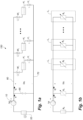
- Fig. 1 shows a schematic view of a heating system 150 that is to be balanced via the calculations provided by the app running on the handheld communication device.
- the heating system 150 comprises a flow system comprising a supply flow line 60 and a return flow line 70.
- a heat source 55 e.g. in form of a boiler, and a pump 10 are coupled to the flow system.
- a plurality of heating elements H 1 -H n are coupled in parallel between the supply flow line 60 and the return flow line 70 in separate hydraulic lines L 1 -L n .
- the heating elements may for instance be radiators or floor heating pipes and each comprise an inlet on the supply flow side and an outlet on the return flow side.
- Each of the hydraulic lines L 1 -L n are provided with a dedicated balancing valve V 1 -V n .
- the balancing valves V 1 -V n are provided on the outlet side of the heating elements H 1 -H n . However, they may also be provided on the inlet side of the heating elements H 1 -H n , and it is also possible that some of the balancing valves are arranged on the inlet side, whereas others are arranged on the outlet side.
- the balancing valves V 1 -V n are utilised to balance the overall flow of the heating system 150, e.g. in order to optimise the overall energy consumption of the heating system 150 and to provide an even heating of the total area that the heating system 150 heats.
- the balancing valves are balanced such that a design flow is achieved for each of the heating elements H 1 -H n .
- the design flow of a heating element corresponds to the optimum flow rate to achieve that the intended power or heat consumption of the room and the emitted power or heat from the heating element are identical.
- the design flow in other words corresponds to the optimum flow to achieve that the heating fluid experiences the optimum temperature loss from the supply line to the return line as it passes the heating element.
- the design flow is estimated on basis of a design point of the system, which is based e.g. on predetermined temperatures for the room temperature (e.g. 22 degrees Celsius) and the outside temperature (e.g. -12 degrees Celsius).
- each of the heating elements H 1 -H n are arranged to emit heat to a given room or space. While each of the heating elements H 1 -H n in Fig. 1 are depicted as a single heating element, it is recognised that each room or space may comprise two or more heating elements H 1 -H n , e.g. two radiators arranged in series.
- Each of the hydraulic lines L 1 -L n have an individual hydraulic resistance R 1 -R n (also called a flow resistance) and the boiler 55 has an internal hydraulic resistance R 0 .
- the heating system 150 may optionally comprise a bypass line 65, which may be provided with a separate bypass valve.
- the bypass line 65 has a hydraulic resistance R b .
- an accurate hydraulic model is needed, including an accurate estimate of the flow resistances R 0 of the boiler 55 and the flow resistances R b of the bypass line 65, respectively.
- suppliers of heaters, such as boilers may provide manuals stating the flow resistance of the heater, such numbers are seldom accurate, since even small variations in the bends of the pipe coils and so forth may influence the flow resistance severely. Further, the flow resistance may change over time due to wear or changes to the overall system.
- the present invention provides a method and a system for accurately calculating a hydraulic model of the heating system, whereby a more accurate balancing may be achieved.
- the pump 10 provides a differential pressure ⁇ p and a flow rate q to the system.
- the pressure and flow rate are not identical to the pressure differential ⁇ p s of the flow system and the flow rate q s of the heating system 150.
- Each of the heating elements H 1 -H n may additionally comprise an additional adjustment valve W 1 -W n in order for a user to be able to adjust the flow and the heating to a level below or above the design settings.
- each element or hydraulic line is represented by a flow resistance.
- the boiler 55 is represented by an internal flow resistance Ro
- the bypass line including the possible bypass valve is represented by a flow resistance R b .
- Each of the flow loops containing a heating element and a dedicated balancing valve as well as the optional regulation valve are represented by a flow resistance R x . It is seen that the resulting flow resistance for one loop is the total flow resistance of the heating element and the valve(s).
- the method according to the invention involves the steps of setting the balancing valves in predetermined settings and measuring the corresponding flow rate q through the pump 10 and the pressure difference ⁇ p across the pump 10. From the sequence and measurements, the hydraulic model as well as the design flow for each of the balancing valves may be calculated. The measurements may be carried out by sensors implemented in the pump 10 or by separate sensors. The pressure difference ⁇ p and the flow rate q may also be determined indirectly from other flow dependent parameters, such as the electrical power and/or an electrical current of pump.
- the handheld communication device may communicate wirelessly with the pump 10 or sensors in order to obtain an automatic readout of the flow rate and pressure difference. This may be carried out by a direct wireless communication between the pump or sensor and the handheld communication device. However, it is also possible, as explained with reference to Figs. 2-5 , to use an electronic converter unit for a pump unit, which may read out an operating status of the pump unit and relay and optionally amplify the readout to the handheld communication device.
- Fig. 2 shows a perspective view of a pump unit 10 or pump assembly.
- the pump unit 10 comprises a housing 12 or terminal box, which has a front end 14 or display, which may be provided with a number of display units 16, which may provide a simple indication of an operating status of the pump unit.
- an electronic converter unit may make it possible to simplify the front end 14 even further, as the necessity of having a display is alleviated, whereby the production cost and thereby the price for the end-consumer may be lowered considerably.
- the front end 14 may be provided without the display units 16.
- the front end 14 is further provided with a light source 18, e.g. in form of a single photo diode or a plurality of photo diodes.
- the pump unit 10 is under operation installed in a pipe system via the pipe flanges 20, 21.
- the housing 12 or terminal box of the pump unit 10 houses an electrical motor and a drive shaft as well as control circuitry of the pump unit 10.
- the electric motor and pump parts are integrated into a common housing.
- the electrical motor and the pump may be arranged in separate housings.
- the control circuitry may control the light source 18 to emit light to display an operating status of the pump unit 10, whereby more detailed information about the operating status may be read out from the pump unit 10, e.g. as binary optical signals.
- the front end 14 of the pump unit 10 may further be provided with one or more buttons, which may be pressed in order to initialise a sequence, where the light source 18 is brought to emit light in order to display the operating status of the pump unit 10.
- the electronic converter unit 30 omprises a photo detector (not shown in Fig. 3 ) for detecting light emitted from the light source 18 of the pump unit 10, and which is arranged on or near a side of the electronic converter unit 30, which when attached to the housing 12 of the pump unit 10 faces towards the housing 12 of the pump unit 10.
- the electronic converter unit 30 may further comprise a number of attachment parts 32, e.g. in form of retractable mechanical fasteners (not shown in Fig. 3 ).
- a front end of the electronic converter unit 30 may further be provided with an indicator or display 34, e.g. for giving an indication of a signal strength of the measured optical signal emitted from the light source 18 of the pump unit 10.
- the display 34 may thus provide a visual feedback to a user providing information about the alignment of the photo detector relative to the light source 18 of the pump unit 10.
- the light source 18 may for instance communicate with the electronic converter unit at a communication rate of e.g. 9600 Baud.
- the diode 18 can be a dedicated communication diode built into the front end 14 with the sole purpose of providing an optical communication with another electronic device. Alternatively, it can have two functions, namely acting as a visual status indicator to humans in the normal situation, and acting as communication diode in case the electronic converter unit is placed on the front end 14.
- the diode 18 other display units 16, i.e. segmented light emitting diodes, can act as the signal source.
- the segments can be turned on or off in a predetermined pattern that can be read and interpreted by the electronic converter unit 30.
- these diodes are already present in the pump, i.e. no design changes have had to be made to the electronics or the front end of the pump; the diodes already at hand are simply getting a further task, namely the task of performing optical communication with the electronic converter unit 30.
- the communication between the electronic converter unit 30 and the pump unit 10 is not made with light signals.
- any signal source can be used for the communication, e.g. sound signals generated by the pump and received by the electronic converter unit. It may also be possible to utilise electrical signals sent over a wired connection, between the pump unit and the electronic converter unit. Such connection can be established with a plug connector in the electronic converter unit and a mating socket connection in the housing of the pump unit, e.g. in the front end 10.
- the electronic converter unit 30 is further provided with a communication unit for converting the detected signal, such as the optical signal, to an electrical signal, such as infrared or a radio signal, e.g. based on GSM, CDMA, 3G, 4G, , and Bluetooth ® 36.
- a communication unit for converting the detected signal, such as the optical signal, to an electrical signal, such as infrared or a radio signal, e.g. based on GSM, CDMA, 3G, 4G, , and Bluetooth ® 36.
- the front end of the electronic converter unit 30 may be provided with one or more buttons to initialise a sequence, where the electronic converter unit 30 detects optical signals emitted from the light source 18 of the pump unit 10 and converts the optical signals to electrical signals and transmits the electrical signals to an external communication unit, such as a smart phone.
- Fig. 4 shows a system 100 for checking the operating status of a pump unit 10.
- the system 10 comprises the afore-mentioned pump unit 10 and the electronic converter unit 30.
- the electronic converter unit 30 is here shown attached to the front end 14 of the housing 12 of the pump unit 10, such that the photo detector of the electronic converter unit 30 is aligned with the light source 18 of the pump unit 10.
- the electronic converter unit 10 is attached to the front end 14 of the pump unit 10 by use of mechanical fasteners 32, which are connected to sides of the housing 12 of the pump unit 10.
- the electronic converter unit 10 detects the optical signals emitted from the pump unit 10 and converts them to radio signals, which are transmitted to an external communication unit 50 in form of a smart phone having a display 52.
- the smart phone 50 comprises an app, which is installed and running on the smart phone 50.
- the smart phone 50 and app are adapted to receive and process the radio signals sent from the electronic converter unit 30 so as to display the operating status of the pump unit 10 on the display 52 of the smart phone 50.
- the app may further be provided with a function to control the pump unit by setting the operating or drive parameters of the pump unit 10.
- the smart phone 50 may send the control instructions via the electronic converter unit 30.
- Figs. 5a-d shows an alternative design for an electronic converter unit 30' for use in the invention, where the electronic converter unit 30' is shaped as an elongated unit.
- the electronic converter unit 30' comprises the same features as the electronic converter unit shown in Fig. 3 . Accordingly, only the differences between the two embodiments are described in the following. Similar to the embodiment of Fig. 3 , the electronic converter unit 30' comprises a housing 31', which houses the electronic circuitry of the electronic converter unit 30'. A front end of the electronic converter unit 30' may further be provided with an indicator or display 34', e.g. for giving an indication of a signal strength of the measured optical signal emitted from the light source 18 of the pump unit 10. The display 34' may thus provide a visual feedback to a user providing information about the alignment of the photo detector relative to the light source 18 of the pump unit 10.
- the electronic converter unit 30' comprises a first mechanical fastener 32', which is slidable engaged with a main part of the electronic converter unit and may be extended from a first end of the electronic converter unit 30'.
- the electronic converter unit 30' further comprises a second mechanical fastener 32" at a second end of the unit 30'.
- the distance between the two mechanical fasteners 32', 32" may be varied so that they can mechanical engage sides of the frontend of the pump unit 10.
- the electronic converter unit 30' may further be designed such that the first mechanical fastener 32', when arranged in a closed state, covers and protects an aperture (e.g.
- the mechanical fasteners 32' and 32" may be provided with small rubber pads, placed in the area where they engage with the pump housing. In this way the electronic converter unit 30 is mechanically better fixated to the pump housing and accommodate the shape of the housing.
- the electronic converter unit 30' may further be designed such that a small part 35' of the unit 30' protrudes beyond the housing of the pump unit 10, when the electronic converter unit 30' is arranged on the front end 14 of the pump unit, as shown in Fig. 5d . This may for instance be achieved by letting the second mechanical fastener 32" being spaced slightly from an end face of the unit 30'.
- An antenna may be arranged in the protruding part 35' of the electronic converter unit 30', which may in some instances provide a stronger signal to the handheld communication device.
- the communication between the external communication device 50 and the pump unit 10 is done directly between the units, i.e. without the electronic converter unit 30.
- the pump unit incorporates means for communicating wirelessly with the external communication device, either via optical communication or, by way of example, via radio frequency frequency communication, Bluetooth ® , GSM, CDMA, 3G or 4G.
- the pump unit incorporates in its internal software programme storage the instructions for balancing a heating system according to the invention, and the programme for calculating the design flows and hydraulic resistances of the heating system. The app has so to speak been moved from the external communication device into the pump unit.
- Fig. 6 shows a flow chart that illustrates the overall steps carried out in a method according to the invention of balancing a heating system 150 as shown in Fig. 1a .
- step A measurements for determining the flow rate and the pressure difference are carried out for each of the heating elements H 1 -H n .
- the measurements may be input into an app running on a handheld communication device or they may be read into the app automatically via wireless communication with the pump 10 or sensors.
- a hydraulic model for the heating system is calculated in step B).
- a design flow for each of the heating elements is calculated in step C).
- the operator or service technician may the adjust the balancing valves V 1 -V n of the heating system 150 in order for the flow through the individual heating elements H 1 -H n to meet the design flow.
- optimum pump settings for the pump 10 may be calculated, and a pump curve of the pump 10 may be adjusted accordingly in order to lower the overall energy consumption of the pump 10 and the heating system 150, thereby lowering the carbon footprint of the heating system 150.
- the measurements may be carried out a predetermined time after balancing valve V i has been opened or until the measurement values have stabilised in order to ensure that the flow has stabilised. Depending on the heating system 150, this typically takes a few seconds to a few minutes.
- the operator then in a third substep A3) closes balancing valve V i .
- the operator then moves onto balancing valve V i + 1 .
- Substeps A1) to A3) are repeated for all the balancing valves V 1 -V n .
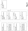
- Fig. 8 shows a flow chart that breaks down step B) of Fig. 7 into substeps.
- a service technician opens balancing valve V j and closes all other balancing valves V 1 -V n .
- the pressure differential ⁇ p j and flow rate q j of the given flow setting are determined and entered into the app (either via input or automatic reading).
- a third step B3) or service technician opens balancing valve V k and closes all other balancing valves V 1 -V n .
- a fourth substep B4) the pressure differential ⁇ p k and flow rate q k of the given flow setting are determined and read into the app (either via input or automatic reading).
- both balancing valve V j and V k are opened, and in a sixth substep B6), the pressure differential ⁇ p jk and flow rate q jk of the given flow setting are measured and read into the app.
- the method proceeds to substep B7), and calculates the hydraulic model including the hydraulic resistance R 0 of the boiler 55. If the heating system comprises a bypass line 65, two additional substeps Bb1) and Bb2) have to be carried out in order to calculate the hydraulic resistance R b of the bypass line 65. In the first additional substep Bb1), all balancing valves V 1 -V n are closed, and in the second additional substep Bb2), the corresponding differential pressure ⁇ p b and flow rate q b of the given flow setting are measured and read into the app.
- substeps B1)-B4) corresponds to substeps A1)-A3). Accordingly, the measurements from step A) may also be used for calculating the hydraulic model. Further, it is clear that balancing valve V j and V k may be chosen arbitrarily in the system. It is also possible to use more than two valves for calculating the hydraulic model, in which case the variables of the hydraulic model may be verified and/or over-determined in order to obtain a higher statistical significance for the hydraulic model.
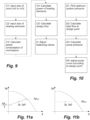
- Fig. 9 shows a flow chart that breaks down steps C) and D) of Fig. 6 into substeps.
- the rooms or spaces to be heated as well as the heating elements H 1 -H n of the heating system 150 are mapped. This may be carried out by inputting the area or volume of the room or space to be heated as well as the needed power per square meter to obtain a temperature equilibrium at room temperature, and the size of the heating elements, e.g. the total area of radiators use for heating the room or space.
- a further characteristic that may be entered is the kind of room, i.e. a living room, kitchen, bedroom, toilet or a hall.
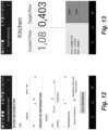
- the characteristics may be mapped by inputting the values into an app on a smart phone or the like, e.g. as shown in Fig. 12 .
- the power consumption or loss at temperature equilibrium of the room may also be calculated in substep C3).
- the needed emission power or heat for the heating element may be calculated in substep C4), which in turn makes it possible to calculate the design flow, which is needed in order to achieve the required emission of heat from the heating element, as the heating fluid passes through the heating element.
- each of the balancing valves V 1 -V n may be set in sequence so as to meet the design flow for each heating element H 1 -H n , e.g. by tracking the flow rate as the corresponding balancing valve is opened.
- the current flow e.g. an estimate of the actual flow
- the kitchen line is shown on the screen.
- the target flow, or desired value, as calculated by the app, which uses the hydraulic model with parameter values determined in step B) is also shown, and the operator is now adjusting the balancing valve to lower the flow rate through the line in order to meet the target flow.
- the operator Once the target flow is equal to or close to the target flow the operator must press the "Done" button, and can via "Next" continue to balance the radiator in the next room.
- a report is generated by the app, and the report can be accessed from the app or sent by email to relevant recipients.
- a first substep E1 the optimum system pressure ⁇ p s is found. This may be carried out by determining which hydraulic line that requires the highest pressure when calculating a required system pressure provided by the pump 10. Further, in substep E2), the total required flow at the design point is calculated. Based on the calculation of substep E1) and E2), the needed pump settings may in substep E3) be calculated based as a sum of the required system pressure ⁇ p s , a pressure loss of the boiler 55, and a given robustness factor of the heating system. The robustness factor may for instance be set to 0-15% of the required system pressure ⁇ p s . In a final substep E4, the pump curve of the pump 10 is adjusted according to the required settings at the design point.
- the pump curve may for instance be adjusted such that the needed pressure and a reference pressure of the pump are coinciding with a proportional graph as shown in Fig. 11a . It may also be assumed that the needed pressure and the reference pressure are arranged on a constant value as shown in Fig. 11b , in which case the reference pressure is set equal to the needed pressure.
- Such adjustment is typically done by changing the rotational speed of the rotor and hence the impeller in the pump.
- the invention can be implemented by using a centrifugal pump, which incorporates control electronics for regulating the rotational speed.
- FIG. 1 A sketch of such a heating system 150 is shown in Fig. 1 .
- a well-balanced system as a system, where at the design load and design temperatures (e.g. -12°C outdoor and 22°C room temperature) the heat emitted from the heat emitters equals the heat losses of the rooms, also called the design point of the heating system. Under these conditions a fully opened valve should not lead to a higher flow than required to emit the heat that accommodates the heat losses. A higher flow is avoided by adjusting the balancing valves at each of the heat emitters as afore-mentioned described with relation to design flow and design point of the heating system.
- design load and design temperatures e.g. -12°C outdoor and 22°C room temperature
- bypass resistance R b ⁇ p 1 q 1 2 ⁇ R 0
- This system pressure and flow rating is in the following used in the balancing calculation, as this corresponds to the flow through the heating elements and the pressure across the valve, radiator, and piping.
- K rad defines the size of the given radiator, and may together with ⁇ k be found from look-up tables
- T s is the defined supply temperature at the design conditions
- T a is the expected room temperature, typically 22 degrees Celsius
- n 1.3 is a standard exponent for simple radiator models.
- the first step in the balancing procedure is to find the optimal system pressure.
- valves should be adjusted such that the actual flow q j equals the reference flow q r,j .
- a proportional pressure curve (as shown in Fig. 11a ) or a constant pressure curve (as shown in fig. 11b ), which contain the design point must be chosen.
- the proportional pressure curve is shown together with the design point ( q ; ⁇ p)
- the constant curve is shown together with the design point ( q ; ⁇ p ).
Landscapes
- Engineering & Computer Science (AREA)
- General Engineering & Computer Science (AREA)
- Mechanical Engineering (AREA)
- Physics & Mathematics (AREA)
- Thermal Sciences (AREA)
- Chemical & Material Sciences (AREA)
- Combustion & Propulsion (AREA)
- Computer Networks & Wireless Communication (AREA)
- Signal Processing (AREA)
- Structures Of Non-Positive Displacement Pumps (AREA)
- Control Of Non-Positive-Displacement Pumps (AREA)
- Compressor (AREA)
- Control Of Positive-Displacement Pumps (AREA)
- Electromagnetism (AREA)
- General Physics & Mathematics (AREA)
- Steam Or Hot-Water Central Heating Systems (AREA)
Claims (15)
- Procédé d'équilibrage d'un système de chauffage (150), dans lequel le système de chauffage comprend :- un système d'écoulement comprenant une conduite d'écoulement d'alimentation (60) et une conduite d'écoulement de retour (70),- une source de chaleur (55) et au moins une première pompe (10) couplée au système d'écoulement et pompant du fluide à travers la source de chaleur vers le système d'écoulement, et- une pluralité de conduites hydrauliques (L1-Ln ) entre la conduite d'écoulement d'alimentation et la conduite d'écoulement de retour, dont au moins un certain nombre comportent un élément chauffant (H1-Hn ) avec une vanne d'équilibrage dédiée (V1-Vn ) et en option une vanne de régulation (W1-W2 ), le procédé comprend les étapes consistant à :A) effectuer une ou plusieurs mesures pour chacune des conduites hydrauliques en ouvrant une seule conduite hydraulique et en déterminant un débit (q) à travers la pompe et une différence de pression (Δp) de part et d'autre de la pompe, caractérisé en ce que le procédé comprend en outre les étapes consistant à :B) établir un modèle hydraulique pour au moins une partie du système de chauffage sur la base du débit et de la différence de pression déterminés d'après au moins deux mesures provenant de l'étape A), et au moins une mesure supplémentaire pour au moins deux conduites hydrauliques provenant de l'étape A), ladite au moins une mesure supplémentaire étant effectuée alors que lesdites au moins deux conduites hydrauliques sont ouvertes,C) spécifier un débit souhaité (
qj ) pour chacune des conduites hydrauliques, etD) régler une ou plusieurs des vannes d'équilibrage dédiées (V1-Vn ) afin de satisfaire au débit souhaité (qj ) pour chacune des conduites hydrauliques en utilisant le modèle hydraulique. - Procédé selon la revendication 1, dans lequel le modèle hydraulique est utilisé pour calculer un débit (qs ) dans le système de chauffage, et dans lequel ledit débit (qs ) dans le système de chauffage est comparé au débit souhaité (
qj ) pour chacune des conduites hydrauliques afin de régler dans l'étape D) lesdites une ou plusieurs des vannes d'équilibrage dédiées (V1-Vn ). - Procédé selon la revendication 1 ou 2, dans lequel l'étape consistant à établir un modèle hydraulique du système de chauffage est effectuée par les étapes suivantes consistant à :B1) ouvrir une première vanne d'équilibrage dédiée et fermer le reste de la pluralité de vannes d'équilibrage afin d'établir un premier réglage de débit pour le système d'écoulement,B2) mesurer une différence de pression et un débit pour le premier réglage de débit,B3) ouvrir une seconde vanne d'équilibrage dédiée et fermer le reste de la pluralité de vannes d'équilibrage afin d'établir un second réglage de débit pour le système d'écoulement,B4) mesurer une différence de pression et un débit pour le second réglage de débit,B5) ouvrir la première vanne d'équilibrage et la seconde vanne d'équilibrage afin d'établir un troisième réglage de débit pour le système d'écoulement,B6) déterminer une différence de pression et un débit pour le troisième réglage de débit, etB7) calculer un modèle hydraulique pour système de chauffage sur la base de mesures provenant des étapes B2), B4), et B6), et de préférence le modèle hydraulique au moins comprenant un calcul de la résistance hydraulique R0 dans la source de chaleur, par exemple l'étape B) comprenant en outre l'étape supplémentaire consistant à fermer toutes les vannes d'équilibrage afin d'établir un réglage de débit de dérivation et effectuer une mesure afin de déterminer une différence de pression et un débit pour le réglage de débit de dérivation, et l'étape B7) étant également déterminée sur la base de la mesure provenant de ladite étape supplémentaire, et en option le modèle hydraulique au moins comprenant un calcul de la résistance hydraulique Rb d'une conduite de dérivation du système de chauffage.
- Procédé selon l'une quelconque des revendications 2-3, dans lequel les étapes de mesure B1-B4 sont effectuées pendant l'étape A).
- Procédé selon l'une quelconque des revendications 2-4, dans lequel l'étape visant à établir un modèle hydraulique du système de chauffage est effectuée pour différents ensembles de deux éléments chauffants et vannes d'équilibrage dédiées.
- Procédé selon l'une quelconque des revendications précédentes, dans lequel l'étape visant à calculer le débit souhaité pour les éléments chauffants individuels est basée sur une dimension d'un espace que l'élément chauffant individuel est destiné à chauffer, par exemple la surface de sol ou le volume de la zone, et/ou sur une dimension dudit élément chauffant.
- Procédé selon l'une quelconque des revendications précédentes, dans lequel une alarme est déclenchée :
si le débit souhaité de l'un des éléments chauffants individuels est plus élevé que le débit maximum du système, et/ou si une différence entre une température d'alimentation et une température de retour d'un élément chauffant individuel est inférieure à un seuil prédéfini, ou encore si la température de retour est supérieure à un seuil prédéfini, et/ou si une température de retour calculée est inférieure à un seuil prédéfini. - Procédé selon l'une quelconque des revendications précédentes, dans lequel le procédé comprend en outre l'étape consistant à déterminer quelle est la vanne d'équilibrage dédiée qui demande la pression la plus élevée, et dans lequel une pression de système requise, fournie par la pompe, est ensuite calculée sur la base de ladite vanne d'équilibrage dédiée.
- Procédé selon l'une quelconque des revendications précédentes, dans lequel le procédé comprend en outre l'étape supplémentaire consistant à calculer les réglages requis de la pompe et à régler la vitesse de la pompe pour répondre aux réglages requis de la pompe plus un facteur de robustesse donné, par exemple dans lequel le procédé consistant à calculer les réglages requis de la pompe comprend l'étape consistant à calculer un débit requis de la pompe à un point défini du système, et en option dans lequel le débit requis de la pompe est calculé en tant que somme des débits souhaités des conduites hydrauliques individuelles, en option plus un débit pour une conduite de dérivation.
- Procédé selon l'une quelconque des revendications 8-9, dans lequel une pression de pompe requise de la pompe est calculée en tant que somme de la pression requise du système, d'une perte calculée de pression de la source de chaleur, et du facteur de robustesse, ladite perte calculée de pression étant calculée sur la base du modèle hydraulique, par exemple une courbe de pompe de la pompe étant construite sur la base de la pression de pompe requise, calculée, de la pompe.
- Pompe munie de moyens destinés à communiquer avec un dispositif de communication portatif, le pompe étant en outre adaptée, par une application ou un programme logiciel installé(e) dans la pompe, pour calculer un modèle hydraulique destiné à être utilisé dans l'équilibrage d'éléments chauffants d'un système de chauffage, caractérisée par l'utilisation du procédé selon l'une quelconque des revendications 1-10.
- Dispositif de communication portatif exécutant une application pour l'équilibrage d'un système de chauffage, dans lequel le système de chauffage comprend :- un système d'écoulement comprenant une conduite d'écoulement d'alimentation et une conduite d'écoulement de retour,- une source de chaleur et au moins une première pompe couplée au système d'écoulement et pompant du fluide à travers la source de chaleur vers le système d'écoulement, et- une pluralité de conduites hydrauliques entre la conduite d'écoulement d'alimentation et la conduite d'écoulement de retour, dont au moins un certain nombre comportent un élément chauffant avec une vanne d'équilibrage dédiée et en option une vanne de régulation,- l'application est adaptée pour recevoir des entrées relatives à des différences de pression et débits, mesurés à différents réglages des vannes d'équilibrage dédiées, et dans lequel- l'application est adaptée pour calculer un modèle hydraulique pour le système de chauffage sur la base des entrées, et- l'application est adaptée pour calculer dans et afficher sur le dispositif de communication portatif un débit désiré pour chacune des vannes d'équilibrage sur la base des entrées ainsi que du modèle hydraulique calculé, caractérisé en ce que le dispositif de communication portatif est adapté pour effectuer le procédé selon l'une quelconque des revendications 1-10.
- Système d'équilibrage comprenant un système de chauffage et un dispositif de communication portatif selon la revendication 12, dans lequel le système de chauffage comprend : un système d'écoulement comprenant une conduite d'écoulement d'alimentation et une conduite d'écoulement de retour, une source de chaleur et au moins une première pompe couplée au système d'écoulement et pompant du fluide à travers la source de chaleur vers le système d'écoulement, et une pluralité de conduites hydrauliques entre la conduite d'écoulement d'alimentation et la conduite d'écoulement de retour, dont au moins un certain nombre comportent un élément chauffant avec une vanne d'équilibrage dédiée et en option une vanne de régulation.
- Système d'équilibrage selon la revendication 13, dans lequel le dispositif de communication portatif et la pompe du système de chauffage sont adaptés pour communiquer sans fil l'un avec l'autre, par exemple dans lequel le dispositif de communication portatif et la pompe du système de chauffage sont adaptés pour communiquer sans fil l'un avec l'autre via une unité de conversion électronique qui est adaptée à lire une sortie de la pompe, et laquelle unité de conversion électronique est en outre dotée d'un transmetteur destiné à transmettre de la pompe au dispositif de communication portatif des signaux électriques indicatifs de la sortie.
- Procédé d'établissement d'un modèle hydraulique approprié à l'équilibrage et à la régulation d'un système de chauffage, dans lequel le système de chauffage comprend :- un système d'écoulement comprenant une conduite d'écoulement d'alimentation et une conduite d'écoulement de retour,- une source de chaleur et au moins une première pompe couplée au système d'écoulement et pompant du fluide à travers la source de chaleur vers le système d'écoulement, et- une pluralité de conduites hydrauliques et comprenant une première conduite hydraulique et une seconde conduite hydraulique entre la conduite d'écoulement d'alimentation et la conduite d'écoulement de retour, dont au moins un certain nombre comportent un élément chauffant avec une vanne d'équilibrage dédiée et en option une vanne de régulation, le procédé comprend les étapes consistant à :a) ouvrir la première conduite hydraulique et fermer le reste des conduites hydrauliques afin d'établir un premier réglage de débit,b) mesurer une différence de pression et un débit pour le premier réglage de débit pour le système d'écoulement,c) ouvrir la seconde conduite hydraulique et fermer le reste des conduites hydrauliques afin d'établir un second réglage de débit pour le système d'écoulement,d) mesurer une différence de pression et un débit pour le second réglage de débit, caractérisé en ce que le procédé comprend les étapes supplémentaires consistant à :e) ouvrir la première conduite hydraulique et la seconde conduite hydraulique afin d'établir un troisième réglage de débit pour le système d'écoulement,f) mesurer une différence de pression et un débit pour le troisième réglage de débit, etg) calculer un modèle hydraulique pour le système de chauffage sur la base de mesures provenant des étapes b), d), et f).
Applications Claiming Priority (2)
| Application Number | Priority Date | Filing Date | Title |
|---|---|---|---|
| PCT/EP2014/076416 WO2016086986A1 (fr) | 2014-12-03 | 2014-12-03 | Ensemble convertisseur électronique à des fins de montage en rattrapage sur une partie externe d'un boîtier d'une unité de pompage |
| PCT/EP2015/054983 WO2016087057A1 (fr) | 2014-12-03 | 2015-03-10 | Procédé et système pour l'équilibrage d'un système de chauffage |
Publications (3)
| Publication Number | Publication Date |
|---|---|
| EP3227614A1 EP3227614A1 (fr) | 2017-10-11 |
| EP3227614B1 true EP3227614B1 (fr) | 2024-09-11 |
| EP3227614C0 EP3227614C0 (fr) | 2024-09-11 |
Family
ID=52103109
Family Applications (3)
| Application Number | Title | Priority Date | Filing Date |
|---|---|---|---|
| EP15708554.9A Active EP3227614B1 (fr) | 2014-12-03 | 2015-03-10 | Procédé et système pour l'équilibrage d'un système de chauffage |
| EP15711445.5A Active EP3227558B1 (fr) | 2014-12-03 | 2015-03-10 | Unité de convertisseur électronique s'installant rétroactivement sur une partie externe d'un boîtier d'une unité pompe |
| EP15804512.0A Active EP3227559B1 (fr) | 2014-12-03 | 2015-12-03 | Unité de convertisseur électronique pour une pompe et procédé de communication avec l'unité de convertisseur électronique |
Family Applications After (2)
| Application Number | Title | Priority Date | Filing Date |
|---|---|---|---|
| EP15711445.5A Active EP3227558B1 (fr) | 2014-12-03 | 2015-03-10 | Unité de convertisseur électronique s'installant rétroactivement sur une partie externe d'un boîtier d'une unité pompe |
| EP15804512.0A Active EP3227559B1 (fr) | 2014-12-03 | 2015-12-03 | Unité de convertisseur électronique pour une pompe et procédé de communication avec l'unité de convertisseur électronique |
Country Status (4)
| Country | Link |
|---|---|
| US (3) | US11365891B2 (fr) |
| EP (3) | EP3227614B1 (fr) |
| CN (3) | CN107002693A (fr) |
| WO (4) | WO2016086986A1 (fr) |
Families Citing this family (27)
| Publication number | Priority date | Publication date | Assignee | Title |
|---|---|---|---|---|
| WO2016086986A1 (fr) * | 2014-12-03 | 2016-06-09 | Grundfos Holding A/S | Ensemble convertisseur électronique à des fins de montage en rattrapage sur une partie externe d'un boîtier d'une unité de pompage |
| US20170170979A1 (en) | 2015-12-15 | 2017-06-15 | Pentair Flow Technologies, Llc | Systems and Methods for Wireless Control and Monitoring of Residential Devices |
| US10711788B2 (en) | 2015-12-17 | 2020-07-14 | Wayne/Scott Fetzer Company | Integrated sump pump controller with status notifications |
| EP3443423B1 (fr) * | 2016-04-15 | 2021-11-03 | Belimo Holding AG | Adaptateur de commande destiné à être fixé à un appareil d'un système de chauffage-ventilation-climatisation |
| WO2018106726A1 (fr) | 2016-12-06 | 2018-06-14 | Pentair Flow Technologies, Llc | Dispositif de commande de système de pompe connecté et son procédé d'utilisation |
| EP3244641A1 (fr) * | 2016-12-20 | 2017-11-15 | Grundfos Holding A/S | Autorisation d'une communication de données avec un module de pompe à commande électronique |
| USD893552S1 (en) | 2017-06-21 | 2020-08-18 | Wayne/Scott Fetzer Company | Pump components |
| WO2019051547A1 (fr) * | 2017-09-13 | 2019-03-21 | Nymet Innovations Pty Ltd | Dispositifs, applications et systèmes de commande de pompe |
| DE102017123560B4 (de) * | 2017-10-10 | 2024-09-12 | Eut Edelstahl Umformtechnik Gmbh | Selbstregulierende Einstellvorrichtung für ein Durchflussregelventil |
| CN108087963B (zh) * | 2017-12-20 | 2020-03-10 | 大连海事大学 | 一种基于体感温度的智能楼宇控制系统 |
| USD890211S1 (en) | 2018-01-11 | 2020-07-14 | Wayne/Scott Fetzer Company | Pump components |
| DE102018200645B3 (de) | 2018-01-16 | 2019-05-09 | Magna Powertrain Bad Homburg GmbH | Fluidische Maschine |
| IT201800003117A1 (it) * | 2018-02-28 | 2019-08-28 | Dab Pumps Spa | Assemblato di elettropompa centrifuga con dispositivo migliorato di interfaccia utente |
| EP3546840A3 (fr) * | 2018-03-30 | 2020-05-27 | Bosch Termoteknik Isitma ve Klima Sanayi Ticaret Anonim Sirketi | Chauffe-eau |
| CN108915980B (zh) * | 2018-06-05 | 2020-01-10 | 河北工程大学 | 河床式取水构筑物 |
| SE543008C2 (sv) * | 2018-11-22 | 2020-09-22 | Stockholm Exergi Ab | Förfarande och system för balansering av massflöde under produktionsstörning eller -brist i ett fjärrvärmenät |
| SE543709C2 (en) * | 2019-04-17 | 2021-06-22 | Pandrol Ab | Mobile energy supply unit for hand-held hydraulic tools and method for operating a hand-held hydraulic tool |
| EP3734396B1 (fr) | 2019-04-29 | 2021-09-08 | Grundfos Holding A/S | Système de commande et procédé de commande d'un système de distribution de fluide |
| CN110332604A (zh) * | 2019-06-17 | 2019-10-15 | 合肥瑞纳节能工程有限公司 | 一种换热站一次侧水流量的调节方法及系统 |
| CN114222891B (zh) * | 2019-07-22 | 2023-12-05 | 贝利莫控股公司 | 用于平衡循环网络的方法和系统 |
| IT201900012846A1 (it) * | 2019-07-25 | 2021-01-25 | Dab Pumps Spa | Dispositivo perfezionato di controllo e gestione di una o più elettropompe |
| CN112032800B (zh) * | 2020-09-09 | 2021-07-06 | 山东鲁航智能科技有限公司 | 一种智能化管网平衡系统及其调控方法 |
| US11935393B2 (en) * | 2020-11-10 | 2024-03-19 | Grace Technologies, Inc. | Smart wireless communication device |
| AU2022226959B2 (en) * | 2021-02-25 | 2025-11-06 | Zodiac Pool Systems Llc | User interface for pumps for swimming pools and spas |
| WO2023007332A1 (fr) * | 2021-07-29 | 2023-02-02 | Ariston S.P.A. | Procédé d'équilibrage hydraulique de système de chauffage d'espace |
| EP4163565B1 (fr) | 2021-10-05 | 2024-07-31 | Carrier Corporation | Terminal de communication en champ propre (nfc) pour fixation à une caisson d'une unité extérieure |
| DE102022209157A1 (de) * | 2022-09-02 | 2024-03-07 | Robert Bosch Gesellschaft mit beschränkter Haftung | Drahtlose Kontrollvorrichtung für Heizsysteme und/oder Smarthome-Systeme |
Family Cites Families (43)
| Publication number | Priority date | Publication date | Assignee | Title |
|---|---|---|---|---|
| FR2547396B1 (fr) * | 1983-06-09 | 1985-07-12 | Sdecc | Procede d'equilibrage d'une installation de chauffage central de type bitube et installation pour la mise en oeuvre de ce procede |
| GB2149176B (en) | 1983-10-26 | 1988-07-13 | Stc Plc | Addressing liquid crystal displays |
| DE3529257C2 (de) | 1985-08-16 | 1996-09-26 | Forschungsgesellschaft Heizung | Verfahren und Anordnung zur Ermittlung der Wärmeabgabe von Heizflächen einer Heizungsanlage |
| DE3529256C2 (de) * | 1985-08-16 | 1994-06-16 | Forschungsgesellschaft Heizung | Verfahren und Anordnung zum hydraulischen Abgleichen eines Heizkreislaufs |
| DE3828207A1 (de) * | 1988-08-19 | 1990-02-22 | Oplaender Wilo Werk Gmbh | Diagnosestecker |
| FR2711775B1 (fr) * | 1993-10-21 | 1996-02-02 | Tour Andersson Sa | Dispositif de contrôle et de mesure énergétique. |
| FR2746168B1 (fr) | 1996-03-14 | 1998-04-30 | Procede d'equilibrage d'un reseau de distribution de fluide non compressible a deux tubes, a plusieurs branches ou colonnes derivees | |
| DE10018866A1 (de) * | 2000-04-14 | 2001-10-25 | Grundfos As | Pumpenaggregat |
| ATE442757T1 (de) | 2000-06-07 | 2009-09-15 | Tyco Electronics Logistics Ag | Verfahren und system zur überwachung und steuerung von arbeitskomponenten |
| GB2405224B (en) * | 2001-01-30 | 2005-05-25 | Aqualisa Products Ltd | Water mixing valve apparatus |
| US7009530B2 (en) * | 2001-09-13 | 2006-03-07 | M&Fc Holding, Llc | Modular wireless fixed network for wide-area metering data collection and meter module apparatus |
| EP1321912B1 (fr) | 2001-12-22 | 2008-10-29 | Grundfos a/s | Dispositif électrique pour la transmission de données |
| DE20206267U1 (de) * | 2002-04-20 | 2003-08-28 | Leybold Vakuum GmbH, 50968 Köln | Vakuumpumpe |
| US6666042B1 (en) * | 2002-07-01 | 2003-12-23 | American Standard International Inc. | Sequencing of variable primary flow chiller system |
| US7563248B2 (en) * | 2005-03-17 | 2009-07-21 | Smisson-Cartledge Biomedical Llc | Infusion fluid heat exchanger and cartridge |
| DE102007017445C5 (de) * | 2007-04-02 | 2015-08-27 | Alfred Kärcher Gmbh & Co. Kg | Flüssigkeitspumpe |
| US9730078B2 (en) | 2007-08-31 | 2017-08-08 | Fisher-Rosemount Systems, Inc. | Configuring and optimizing a wireless mesh network |
| DE102008003315A1 (de) | 2008-01-07 | 2009-07-09 | Viessmann Werke Gmbh & Co Kg | Heizungsanlage und Verfahren zum Betrieb einer Heizungsanlage |
| US8024161B2 (en) * | 2008-08-19 | 2011-09-20 | Honeywell International Inc. | Method and system for model-based multivariable balancing for distributed hydronic networks |
| CN101344274B (zh) * | 2008-08-25 | 2011-06-15 | 北京硕人时代科技有限公司 | 锅炉供热气候补偿系统及其实现方法 |
| CN101509677A (zh) * | 2009-03-31 | 2009-08-19 | 王彦国 | 高层建筑直接供暖系统的水循环系统及其控制方法 |
| CN201522025U (zh) * | 2009-08-14 | 2010-07-07 | 乔养正 | 太阳能供暖供热水设备 |
| FR2958475B1 (fr) | 2010-03-30 | 2012-09-28 | Sophia Conseil | Systeme de controle. |
| KR101343863B1 (ko) * | 2011-04-15 | 2013-12-20 | 한국건설기술연구원 | 변유량 난방제어장치 및 그 방법 |
| CN103797224B (zh) * | 2011-06-22 | 2016-05-25 | 丰田自动车株式会社 | 电动水泵的控制装置 |
| CH705143A1 (de) * | 2011-06-30 | 2012-12-31 | Belimo Holding Ag | Verfahren und Vorrichtungen zum Abgleichen einer Gruppe von Verbrauchern in einem Fluidtransportsystem. |
| US20130051024A1 (en) * | 2011-08-31 | 2013-02-28 | Moshe Amit | Optical Transmitter Assembly, Optical Transceivers Including the Same, and Methods of Making and Using Such Optical Transmitter Assemblies and Optical Transceivers |
| EP2573403B1 (fr) | 2011-09-20 | 2017-12-06 | Grundfos Holding A/S | Pompe |
| EP2626986A1 (fr) | 2012-02-08 | 2013-08-14 | Grundfos Holding A/S | Moteur électrique avec une unité de signalisation |
| WO2013130799A1 (fr) * | 2012-02-28 | 2013-09-06 | Emerson Climate Technologies, Inc. | Diagnostic et système de télésurveillance de chauffage, de ventilation et de climatisation |
| US9330560B2 (en) * | 2012-05-02 | 2016-05-03 | Flowserve Management Company | Reconfigurable equipment monitoring systems and methods |
| EP2696175B1 (fr) | 2012-08-07 | 2021-09-15 | Grundfos Holding A/S | Procédé de détection du débit d'une pompe à centrifuge |
| CN202904852U (zh) * | 2012-09-27 | 2013-04-24 | 无锡豪居智能科技有限公司 | 基于物联网智能信息化的学习、转换及中继无线控制装置 |
| AT513733A1 (de) | 2012-10-30 | 2014-06-15 | Vaillant Group Austria Gmbh | Verfahren zum hydraulischen Abgleich eines Heizungssystems |
| CH707402A2 (de) * | 2012-12-18 | 2014-06-30 | Belimo Holding Ag | Verfahren und Vorrichtung zum Abgleichen einer Gruppe von Verbrauchern in einem Fluidtransportsystem. |
| US8895429B2 (en) * | 2013-03-05 | 2014-11-25 | Eastman Kodak Company | Micro-channel structure with variable depths |
| EP2778423B1 (fr) * | 2013-03-11 | 2018-02-28 | Grundfos Holding A/S | Agrégat de pompe centrifuge |
| US20140314062A1 (en) * | 2013-04-19 | 2014-10-23 | Dennis Loebs | Aquatic-Based Automation Systems |
| CN103778748B (zh) * | 2013-07-08 | 2016-04-13 | 高幼苏 | 一种火场火情实时检测方法及系统 |
| KR20150030098A (ko) * | 2013-09-11 | 2015-03-19 | 한국전자통신연구원 | 착탈형 광 트랜시버 |
| JP6415552B2 (ja) * | 2013-10-16 | 2018-10-31 | エフ.ホフマン−ラ ロシュ アーゲーF. Hoffmann−La Roche Aktiengesellschaft | 携帯医療機器のための通信インターフェースクリップ |
| US9841644B2 (en) * | 2014-05-06 | 2017-12-12 | Apple Inc. | Electrostatic discharge protection structures for liquid crystal displays |
| WO2016086986A1 (fr) * | 2014-12-03 | 2016-06-09 | Grundfos Holding A/S | Ensemble convertisseur électronique à des fins de montage en rattrapage sur une partie externe d'un boîtier d'une unité de pompage |
-
2014
- 2014-12-03 WO PCT/EP2014/076416 patent/WO2016086986A1/fr not_active Ceased
-
2015
- 2015-03-10 EP EP15708554.9A patent/EP3227614B1/fr active Active
- 2015-03-10 CN CN201580066149.2A patent/CN107002693A/zh active Pending
- 2015-03-10 CN CN201580066145.4A patent/CN107003014B/zh active Active
- 2015-03-10 US US15/532,278 patent/US11365891B2/en active Active
- 2015-03-10 US US15/532,238 patent/US10697649B2/en not_active Expired - Fee Related
- 2015-03-10 WO PCT/EP2015/054983 patent/WO2016087057A1/fr not_active Ceased
- 2015-03-10 WO PCT/EP2015/054980 patent/WO2016087056A1/fr not_active Ceased
- 2015-03-10 EP EP15711445.5A patent/EP3227558B1/fr active Active
- 2015-12-03 US US15/532,294 patent/US10132508B2/en active Active
- 2015-12-03 WO PCT/EP2015/078547 patent/WO2016087595A1/fr not_active Ceased
- 2015-12-03 CN CN201580064784.7A patent/CN107002691B/zh active Active
- 2015-12-03 EP EP15804512.0A patent/EP3227559B1/fr active Active
Also Published As
| Publication number | Publication date |
|---|---|
| US20170328367A1 (en) | 2017-11-16 |
| CN107002691A (zh) | 2017-08-01 |
| US10132508B2 (en) | 2018-11-20 |
| WO2016086986A1 (fr) | 2016-06-09 |
| WO2016087595A1 (fr) | 2016-06-09 |
| US11365891B2 (en) | 2022-06-21 |
| CN107002691B (zh) | 2021-04-16 |
| EP3227614A1 (fr) | 2017-10-11 |
| EP3227558A1 (fr) | 2017-10-11 |
| WO2016087057A1 (fr) | 2016-06-09 |
| CN107003014A (zh) | 2017-08-01 |
| CN107002693A (zh) | 2017-08-01 |
| EP3227558B1 (fr) | 2022-05-04 |
| EP3227614C0 (fr) | 2024-09-11 |
| CN107003014B (zh) | 2020-07-24 |
| WO2016087056A1 (fr) | 2016-06-09 |
| EP3227559A1 (fr) | 2017-10-11 |
| US20170272844A1 (en) | 2017-09-21 |
| EP3227559B1 (fr) | 2021-05-19 |
| US10697649B2 (en) | 2020-06-30 |
| US20170328579A1 (en) | 2017-11-16 |
Similar Documents
| Publication | Publication Date | Title |
|---|---|---|
| EP3227614B1 (fr) | Procédé et système pour l'équilibrage d'un système de chauffage | |
| US8109289B2 (en) | System and method for decentralized balancing of hydronic networks | |
| US9897084B2 (en) | Sensorless adaptive pump control with self-calibration apparatus for hydronic pumping system | |
| CN212623758U (zh) | 用于远程测量流经管道控制装置pcd的水特征的系统和该pcd | |
| CN105683661B (zh) | 用于匹配加热曲线的方法 | |
| US11088545B2 (en) | Self-powered utility delivery system | |
| US20170122458A1 (en) | Hot water heater systems and methods for monitoring electronic mixing valves | |
| US20100276502A1 (en) | Method And Apparatus For Commissioning And Balancing A Wet Central Heating System | |
| US20170370362A1 (en) | Direct numeric affinity multistage pumps sensorless converter | |
| CN111912060A (zh) | 一种集中空调系统水力平衡自动调适方法及系统 | |
| CN102759145A (zh) | 供暖系统流量平衡调节方法及流量平衡调节系统 | |
| US20160146647A1 (en) | A gas flow measuring system for electric household appliances | |
| CN108730596A (zh) | 一种多功能供热阀门控制方法及装置 | |
| CN206469471U (zh) | 一种电子恒温式电热水器 | |
| EP3657078B1 (fr) | Procédé de mesure de puissance de sortie d'échangeurs de chaleur | |
| EP3418849A1 (fr) | Ensemble de thermostat d'échangeur de chaleur et procédé de commande d'une vanne d'échangeur de chaleur | |
| WO2023007332A1 (fr) | Procédé d'équilibrage hydraulique de système de chauffage d'espace | |
| WO2026046634A1 (fr) | Procédé de fonctionnement d'une pompe de circulation et procédé de réglage d'une pression de dérivation d'une vanne de dérivation | |
| WO2018208179A1 (fr) | Système de mesure de la consommation d'énergie réelle de radiateurs de chauffage central |
Legal Events
| Date | Code | Title | Description |
|---|---|---|---|
| STAA | Information on the status of an ep patent application or granted ep patent |
Free format text: STATUS: THE INTERNATIONAL PUBLICATION HAS BEEN MADE |
|
| PUAI | Public reference made under article 153(3) epc to a published international application that has entered the european phase |
Free format text: ORIGINAL CODE: 0009012 |
|
| STAA | Information on the status of an ep patent application or granted ep patent |
Free format text: STATUS: REQUEST FOR EXAMINATION WAS MADE |
|
| 17P | Request for examination filed |
Effective date: 20170626 |
|
| AK | Designated contracting states |
Kind code of ref document: A1 Designated state(s): AL AT BE BG CH CY CZ DE DK EE ES FI FR GB GR HR HU IE IS IT LI LT LU LV MC MK MT NL NO PL PT RO RS SE SI SK SM TR |
|
| AX | Request for extension of the european patent |
Extension state: BA ME |
|
| DAV | Request for validation of the european patent (deleted) | ||
| DAX | Request for extension of the european patent (deleted) | ||
| STAA | Information on the status of an ep patent application or granted ep patent |
Free format text: STATUS: EXAMINATION IS IN PROGRESS |
|
| 17Q | First examination report despatched |
Effective date: 20200504 |
|
| GRAP | Despatch of communication of intention to grant a patent |
Free format text: ORIGINAL CODE: EPIDOSNIGR1 |
|
| STAA | Information on the status of an ep patent application or granted ep patent |
Free format text: STATUS: GRANT OF PATENT IS INTENDED |
|
| INTG | Intention to grant announced |
Effective date: 20231113 |
|
| GRAJ | Information related to disapproval of communication of intention to grant by the applicant or resumption of examination proceedings by the epo deleted |
Free format text: ORIGINAL CODE: EPIDOSDIGR1 |
|
| STAA | Information on the status of an ep patent application or granted ep patent |
Free format text: STATUS: EXAMINATION IS IN PROGRESS |
|
| GRAP | Despatch of communication of intention to grant a patent |
Free format text: ORIGINAL CODE: EPIDOSNIGR1 |
|
| STAA | Information on the status of an ep patent application or granted ep patent |
Free format text: STATUS: GRANT OF PATENT IS INTENDED |
|
| INTC | Intention to grant announced (deleted) | ||
| INTG | Intention to grant announced |
Effective date: 20240408 |
|
| GRAS | Grant fee paid |
Free format text: ORIGINAL CODE: EPIDOSNIGR3 |
|
| GRAA | (expected) grant |
Free format text: ORIGINAL CODE: 0009210 |
|
| STAA | Information on the status of an ep patent application or granted ep patent |
Free format text: STATUS: THE PATENT HAS BEEN GRANTED |
|
| AK | Designated contracting states |
Kind code of ref document: B1 Designated state(s): AL AT BE BG CH CY CZ DE DK EE ES FI FR GB GR HR HU IE IS IT LI LT LU LV MC MK MT NL NO PL PT RO RS SE SI SK SM TR |
|
| REG | Reference to a national code |
Ref country code: GB Ref legal event code: FG4D |
|
| REG | Reference to a national code |
Ref country code: CH Ref legal event code: EP |
|
| REG | Reference to a national code |
Ref country code: DE Ref legal event code: R096 Ref document number: 602015089853 Country of ref document: DE |
|
| REG | Reference to a national code |
Ref country code: IE Ref legal event code: FG4D |
|
| U01 | Request for unitary effect filed |
Effective date: 20241010 |
|
| U07 | Unitary effect registered |
Designated state(s): AT BE BG DE DK EE FI FR IT LT LU LV MT NL PT RO SE SI Effective date: 20241029 |
|
| PG25 | Lapsed in a contracting state [announced via postgrant information from national office to epo] |
Ref country code: NO Free format text: LAPSE BECAUSE OF FAILURE TO SUBMIT A TRANSLATION OF THE DESCRIPTION OR TO PAY THE FEE WITHIN THE PRESCRIBED TIME-LIMIT Effective date: 20241211 |
|
| PG25 | Lapsed in a contracting state [announced via postgrant information from national office to epo] |
Ref country code: GR Free format text: LAPSE BECAUSE OF FAILURE TO SUBMIT A TRANSLATION OF THE DESCRIPTION OR TO PAY THE FEE WITHIN THE PRESCRIBED TIME-LIMIT Effective date: 20241212 |
|
| PG25 | Lapsed in a contracting state [announced via postgrant information from national office to epo] |
Ref country code: HR Free format text: LAPSE BECAUSE OF FAILURE TO SUBMIT A TRANSLATION OF THE DESCRIPTION OR TO PAY THE FEE WITHIN THE PRESCRIBED TIME-LIMIT Effective date: 20240911 |
|
| PG25 | Lapsed in a contracting state [announced via postgrant information from national office to epo] |
Ref country code: ES Free format text: LAPSE BECAUSE OF FAILURE TO SUBMIT A TRANSLATION OF THE DESCRIPTION OR TO PAY THE FEE WITHIN THE PRESCRIBED TIME-LIMIT Effective date: 20240911 Ref country code: RS Free format text: LAPSE BECAUSE OF FAILURE TO SUBMIT A TRANSLATION OF THE DESCRIPTION OR TO PAY THE FEE WITHIN THE PRESCRIBED TIME-LIMIT Effective date: 20241211 |
|
| PG25 | Lapsed in a contracting state [announced via postgrant information from national office to epo] |
Ref country code: RS Free format text: LAPSE BECAUSE OF FAILURE TO SUBMIT A TRANSLATION OF THE DESCRIPTION OR TO PAY THE FEE WITHIN THE PRESCRIBED TIME-LIMIT Effective date: 20241211 Ref country code: NO Free format text: LAPSE BECAUSE OF FAILURE TO SUBMIT A TRANSLATION OF THE DESCRIPTION OR TO PAY THE FEE WITHIN THE PRESCRIBED TIME-LIMIT Effective date: 20241211 Ref country code: HR Free format text: LAPSE BECAUSE OF FAILURE TO SUBMIT A TRANSLATION OF THE DESCRIPTION OR TO PAY THE FEE WITHIN THE PRESCRIBED TIME-LIMIT Effective date: 20240911 Ref country code: GR Free format text: LAPSE BECAUSE OF FAILURE TO SUBMIT A TRANSLATION OF THE DESCRIPTION OR TO PAY THE FEE WITHIN THE PRESCRIBED TIME-LIMIT Effective date: 20241212 Ref country code: ES Free format text: LAPSE BECAUSE OF FAILURE TO SUBMIT A TRANSLATION OF THE DESCRIPTION OR TO PAY THE FEE WITHIN THE PRESCRIBED TIME-LIMIT Effective date: 20240911 |
|
| PG25 | Lapsed in a contracting state [announced via postgrant information from national office to epo] |
Ref country code: IS Free format text: LAPSE BECAUSE OF FAILURE TO SUBMIT A TRANSLATION OF THE DESCRIPTION OR TO PAY THE FEE WITHIN THE PRESCRIBED TIME-LIMIT Effective date: 20250111 |
|
| PG25 | Lapsed in a contracting state [announced via postgrant information from national office to epo] |
Ref country code: SM Free format text: LAPSE BECAUSE OF FAILURE TO SUBMIT A TRANSLATION OF THE DESCRIPTION OR TO PAY THE FEE WITHIN THE PRESCRIBED TIME-LIMIT Effective date: 20240911 |
|
| PG25 | Lapsed in a contracting state [announced via postgrant information from national office to epo] |
Ref country code: CZ Free format text: LAPSE BECAUSE OF FAILURE TO SUBMIT A TRANSLATION OF THE DESCRIPTION OR TO PAY THE FEE WITHIN THE PRESCRIBED TIME-LIMIT Effective date: 20240911 Ref country code: PL Free format text: LAPSE BECAUSE OF FAILURE TO SUBMIT A TRANSLATION OF THE DESCRIPTION OR TO PAY THE FEE WITHIN THE PRESCRIBED TIME-LIMIT Effective date: 20240911 |
|
| PG25 | Lapsed in a contracting state [announced via postgrant information from national office to epo] |
Ref country code: SK Free format text: LAPSE BECAUSE OF FAILURE TO SUBMIT A TRANSLATION OF THE DESCRIPTION OR TO PAY THE FEE WITHIN THE PRESCRIBED TIME-LIMIT Effective date: 20240911 |
|
| U20 | Renewal fee for the european patent with unitary effect paid |
Year of fee payment: 11 Effective date: 20250325 |
|
| PLBE | No opposition filed within time limit |
Free format text: ORIGINAL CODE: 0009261 |
|
| STAA | Information on the status of an ep patent application or granted ep patent |
Free format text: STATUS: NO OPPOSITION FILED WITHIN TIME LIMIT |
|
| PGFP | Annual fee paid to national office [announced via postgrant information from national office to epo] |
Ref country code: CH Payment date: 20250401 Year of fee payment: 11 |
|
| 26N | No opposition filed |
Effective date: 20250612 |
|
| PG25 | Lapsed in a contracting state [announced via postgrant information from national office to epo] |
Ref country code: MC Free format text: LAPSE BECAUSE OF FAILURE TO SUBMIT A TRANSLATION OF THE DESCRIPTION OR TO PAY THE FEE WITHIN THE PRESCRIBED TIME-LIMIT Effective date: 20240911 |
|
| GBPC | Gb: european patent ceased through non-payment of renewal fee |
Effective date: 20250310 |
|
| PG25 | Lapsed in a contracting state [announced via postgrant information from national office to epo] |
Ref country code: GB Free format text: LAPSE BECAUSE OF NON-PAYMENT OF DUE FEES Effective date: 20250310 |
|
| PG25 | Lapsed in a contracting state [announced via postgrant information from national office to epo] |
Ref country code: IE Free format text: LAPSE BECAUSE OF NON-PAYMENT OF DUE FEES Effective date: 20250310 |
|
| REG | Reference to a national code |
Ref country code: CH Ref legal event code: U11 Free format text: ST27 STATUS EVENT CODE: U-0-0-U10-U11 (AS PROVIDED BY THE NATIONAL OFFICE) Effective date: 20260401 |
|
| U20 | Renewal fee for the european patent with unitary effect paid |
Year of fee payment: 12 Effective date: 20260326 |