EP3227676B1 - Système de détection par photo-ionisation pour matières organiques présentes dans l'eau - Google Patents
Système de détection par photo-ionisation pour matières organiques présentes dans l'eau Download PDFInfo
- Publication number
- EP3227676B1 EP3227676B1 EP15812886.8A EP15812886A EP3227676B1 EP 3227676 B1 EP3227676 B1 EP 3227676B1 EP 15812886 A EP15812886 A EP 15812886A EP 3227676 B1 EP3227676 B1 EP 3227676B1
- Authority
- EP
- European Patent Office
- Prior art keywords
- gas
- sensor
- membrane
- sensor head
- detector
- Prior art date
- Legal status (The legal status is an assumption and is not a legal conclusion. Google has not performed a legal analysis and makes no representation as to the accuracy of the status listed.)
- Active
Links
Images
Classifications
-
- G—PHYSICS
- G01—MEASURING; TESTING
- G01N—INVESTIGATING OR ANALYSING MATERIALS BY DETERMINING THEIR CHEMICAL OR PHYSICAL PROPERTIES
- G01N33/00—Investigating or analysing materials by specific methods not covered by groups G01N1/00 - G01N31/00
- G01N33/18—Water
- G01N33/1826—Organic contamination in water
-
- G—PHYSICS
- G01—MEASURING; TESTING
- G01N—INVESTIGATING OR ANALYSING MATERIALS BY DETERMINING THEIR CHEMICAL OR PHYSICAL PROPERTIES
- G01N27/00—Investigating or analysing materials by the use of electric, electrochemical, or magnetic means
- G01N27/62—Investigating or analysing materials by the use of electric, electrochemical, or magnetic means by investigating the ionisation of gases, e.g. aerosols; by investigating electric discharges, e.g. emission of cathode
-
- G—PHYSICS
- G01—MEASURING; TESTING
- G01N—INVESTIGATING OR ANALYSING MATERIALS BY DETERMINING THEIR CHEMICAL OR PHYSICAL PROPERTIES
- G01N27/00—Investigating or analysing materials by the use of electric, electrochemical, or magnetic means
- G01N27/62—Investigating or analysing materials by the use of electric, electrochemical, or magnetic means by investigating the ionisation of gases, e.g. aerosols; by investigating electric discharges, e.g. emission of cathode
- G01N27/64—Investigating or analysing materials by the use of electric, electrochemical, or magnetic means by investigating the ionisation of gases, e.g. aerosols; by investigating electric discharges, e.g. emission of cathode using wave or particle radiation to ionise a gas, e.g. in an ionisation chamber
- G01N27/66—Investigating or analysing materials by the use of electric, electrochemical, or magnetic means by investigating the ionisation of gases, e.g. aerosols; by investigating electric discharges, e.g. emission of cathode using wave or particle radiation to ionise a gas, e.g. in an ionisation chamber and measuring current or voltage
-
- G—PHYSICS
- G01—MEASURING; TESTING
- G01N—INVESTIGATING OR ANALYSING MATERIALS BY DETERMINING THEIR CHEMICAL OR PHYSICAL PROPERTIES
- G01N33/00—Investigating or analysing materials by specific methods not covered by groups G01N1/00 - G01N31/00
- G01N33/0004—Gaseous mixtures, e.g. polluted air
- G01N33/0009—General constructional details of gas analysers, e.g. portable test equipment
- G01N33/0027—General constructional details of gas analysers, e.g. portable test equipment concerning the detector
- G01N33/0036—General constructional details of gas analysers, e.g. portable test equipment concerning the detector specially adapted to detect a particular component
- G01N33/0047—Organic compounds
-
- G—PHYSICS
- G01—MEASURING; TESTING
- G01N—INVESTIGATING OR ANALYSING MATERIALS BY DETERMINING THEIR CHEMICAL OR PHYSICAL PROPERTIES
- G01N33/00—Investigating or analysing materials by specific methods not covered by groups G01N1/00 - G01N31/00
- G01N33/02—Food
- G01N33/14—Beverages
- G01N33/146—Beverages containing alcohol
Definitions
- This invention relates to detection of gaseous and volatile analytes dissolved in water and other aqueous fluids using a detector within which such materials are sensed in the gaseous phase.
- Analytes of particular interest are volatile organic compounds (VOCs) particularly as found in water and aqueous solutions in concentrations varying from less than a part per billion (ppb, 10 -9 ) to parts per thousand (ppt, 10 -3 ) by mass.
- VOCs volatile organic compounds
- VOCs include irritants, oestrogens, carcinogens and other chemicals harmful to humans, animals and plant life.
- Rigorous standards are laid down for potable water supplies which must be carefully monitored.
- open water such as rivers, lakes and the oceans must be monitored for contamination or pollution to prevent damage to plants, animals or adjoining land.
- Volatile and gaseous compounds dissolved in water are also of interest as analytes due to other deleterious effects, for example in accelerating corrosion of metal pipes and vessels, or simply as indicators of water process quality within certain environments, for example wash water used in an industrial closed loop process or in the detection of alcohols due to fermentation in food stuffs and in brewing.
- a class of such detectors contain a membrane, typically hydrophobic, providing a barrier between the aqueous sensed environment and a detector enclosure, through which the analyte is able to diffuse.
- the detector enclosure contains an aqueous liquid.
- a well known example of this type of sensor is the Clarke electrode', in which dissolved oxygen in water diffuses from the test environment through a sensor membrane into an electrolyte, contained within a sensor cavity which includes the membrane as one containment wall member. The dissolved oxygen is consumed at an electrode proximal to the membrane.
- Patent DE20300514 U1 Achim Rappl, provides another example of this type of detector, again for detecting dissolved oxygen.
- the detector membrane which is in contact with the aqueous fluid on one side, forms the wall of a gaseous enclosure on the other, through which the analyte is able to diffuse.
- this type of detector as a gas partitioned volatile detector.
- US 5,979,219 describes another gas partitioned volatile detector in which the membrane admits volatiles such as ethanol into the sensing gaseous enclosure which is then sensed by a proximal semiconducting gas sensor.
- the invention relies on a pressure relief system being continuously open in order to 'exhaust' gases, not least target volatiles, into the atmosphere [Col 2 lines 11-32, Col 3,lines 26-35] rendering a carrier gas to flush the sensor enclosure unnecessary [Col 2 line 31].
- a problem to be expected with a detector made according to US '219 is that the rate of analyte escape from the detector gaseous chamber will be very slow and highly variable, according to factors which enable more or less rapid escape of gases from the pressure relief outlet to atmosphere at some considerable distance.
- the design may be sufficiently compact to enable detector response and cleardown in the time frame of half a day, as may be useful in brewing, but not within a minute or two, as may be required, for example, in sensing volatiles in a sensor train behind a boat or in a water process stream.
- a further means of analyte removal from a gas partitioned volatile detector may be provided by the gas sensor or gas sensing element itself consuming the analyte, as is illustrated in EP0734516A1 , Commonwealth Scientific and Industrial Research Organisation, which describes an amperommetric oxygen sensor behind a diffusive membrane.
- Analyte detection may be contemplated by way of infrared sensors such as disclosed in US 8,383,046 or by humidity sensors such as disclosed in WO2006/042546 .
- Most prior art to date does not appear to include a gas partitioned volatile detector in which neither does the gas sensing element consume the analyte, nor does the detector use some means of gas evacuation to remove the analyte.
- US 8,383,046 which utilises an IR detector typically having a volume of 400mm 3 .
- This technology is dependent on having a relatively large volume sample in order to register the presence of the analyte.
- the downside of this is that the time taken to fill the chamber (by equilibration of analyte across a sensor membrane) to an appreciable level for a reading to be taken makes for a sensor whose response time is unacceptably high.
- the present invention recognises this and all previously described problems and attempts to mitigate them by way of a novel detector arrangement.
- this type of detector is a gas-equilibrated, volatile-in-liquid detector.
- This detector provides a significant advantage over other gas-partitioned volatile detectors, in prospectively delivering a partial pressure of gas in the gaseous enclosure p in equilibrium with the concentration of gas in the liquid phase, c.
- the gas sensing element in the gas-equilibrated, volatile-in-liquid detector requires only the gas sensing element in the gas-equilibrated, volatile-in-liquid detector to be reliable in sensing a target analyte for the concentration of a volatile in an adjoining liquid phase to be known.
- the detector can provide a measurement of a volatile in a liquid which does not vary directly with the rate of supply of analyte to the sensor, as determined either: by the rate of consumption or dispersion of analyte by components within the detector; or by the permeability or porosity of any intervening membrane.
- gas sensors and gas sensing sub-assemblies suitable for the measurement of analyte in equilibrium with an adjoining liquid phase commonly include a gaseous enclosure characterised by its being contiguous, sometimes unavoidably, with tortuous and convoluted gaseous spaces between sub-assembled components and with capillary leak sites, all of which provide an appreciable sink for analyte when compared to the slow rate of supply and removal of analyte though the partition separating the gas enclosure from the liquid containing the analyte.
- a photoionisation (PID) detector sensor head capable of detecting and measuring organic materials in water, particularly at trace concentrations, which can provide real time measurements in a field environment, with little additional procedure than is required in the use of a typical gas detectors, and which enables easily calculated determination of the concentration of such organic materials in water, when their identity is known.
- PID photoionisation
- a photoionisation detector (PID) sensor head is provided for use in a detector of volatiles in aqueous media as set forth in claim 1 of the appended claims.
- a detector of volatiles in water and aqueous fluids which contains as one member a vapour-porous or vapour-permeable membrane forming a wall of a gaseous enclosure in which concentration of gas in the enclosure is substantively achieved by means of analyte flux through the membrane.
- the membrane may also be sealed to an external wall of the gas-sensing chamber or of a surrounding enclosure, which may form part of a separable gas sensing sub-assembly or easily removable sensor.
- This outer seal may be a peelable adhesive. Conveniently, the two seals are concentric.
- the vapour-porous or vapour-permeable membrane forms an entry point to a second gaseous enclosure external of the gas-sensing chamber. This can reduce the effect of leaks between sub-components of the sensor assembly, by enabling gas equilibration in the space between the gas sensor and walls containing it.
- the membrane sealing the gas sensing sub-assembly or gas sensor it is preferable for the membrane sealing the gas sensing sub-assembly or gas sensor to extend beyond its point of sealing to the sensor to affect a further seal to outer detector components, such that, upon removal of the membrane, the gas sensor or sensor sub-assembly may be removed from the detector.
- the gas sensor or gas sensing sub-assembly it is convenient for the gas sensor or gas sensing sub-assembly to receive gas from an orifice in a planar supporting surface, which is contrived to be in the plane of the termination of detector wall members to which the outer membrane seal is made.
- the membrane must exclude liquid water from the gas-sensing chamber. Conveniently, the membrane is hydrophobic.
- a suitable material may be porous polytetrafluoroethylene (PTFE) or polyvinylidene difluoride (PVDF), either stand alone or as a coating on a porous substrate such as polypropylene.
- PTFE polytetrafluoroethylene
- PVDF polyvinylidene difluoride
- the overall thickness is some 100 - 500 m -6 and the pore size is approximately 0.5 m -6 .
- the seal to the outer membrane member may be effected by means of an adhesive layer on a hydrophobic surface such as PTFE.
- the membrane may contain an annulus of adhesive to effect sealing of the gas sensor or gas sensing subcomponent.
- the seal to the periphery of the chamber orifice is a vapour-impermeable barrier throughout the thickness of the membrane.
- This is normally a weld, particularly ultrasonic, between the membrane material and the gas sensor or gas sensing sub-assembly but can also be an impermeable adhesive penetrating the membrane.
- the invention in a further aspect provides for membrane material between the outer membrane to detector wall seal and the inner gas membrane to gaseous sensor seal or membrane to gaseous sensing sub-assembly seal to be vapour-permeable or vapour-porous.
- porous PTFE it is preferable for all porous surfaces to comprise porous PTFE.
- the vapour detector measures the partial pressure of the organic materials in the vapour phase. Particularly at low concentrations, this measurement is a function of the concentration of the organic material in the liquid water.
- the gas-sensing chamber is so configured as to minimise dead volume therein.
- the internal volume of the gas-sensing chamber is no greater than 100 mm 3 .
- the electrodes or other sensing system components within a sensor or sensing sub-assembly according to the present invention are stacked, with only a modest spacing between the sensing components such that the entire thickness of the sensing enclosure is no greater than a few millimetres.
- the water from which organic volatiles pass through the membrane is in very close proximity to the entirety of the gas sensing enclosure, typically within 2 mm.
- the sensor may include a plurality of electrode contacts which, in an assembled position, lie in a common plane in the gas-sensing chamber and as close as possible to the overlying membrane.
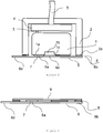
- Figure 1 shows a schematic representation of a gas-equilibrated, volatile-in-water detector, in which a gas sensor 1 is contained within a gas sensor cradle 2.
- the gas sensor is preferably of cylindrical shape, and typically of 20 mm diameter and 16.6 mm height, excluding contact pins 3, as provided as a received industrial standard by gas sensor manufacturers such as Alphasense Ltd, Dynament Ltd and City Technology Ltd.
- the gas sensor preferably is disposed to sit upon, and make electrical connection via 3 to, a small printed circuit board (PCB), 4, itself electrically connected to a cable 5, through which power is delivered to the gas sensor and signals are communicated to and from the sensor to some external means of control such as a computer, via, by way of example, a universal serial port.
- PCB printed circuit board
- the cradle 2 and PCB 4 are positioned so that the face, 1a, of the gas sensor containing a gas sensing orifice 1b, is approximately co-planar with the cradle wall flat surfaces 2a.
- Gas porous PTFE membrane 6, some 280 - 300 m -6 thick, is attached by means of a thin adhesive layer 7 to the sensor face 1a.
- a further portion 6b of the membrane is attached by means of a thin layer of adhesive 8 to the cradle wall flats 2a, thereby forming an entry point to a second gaseous enclosure external of the gas sensor 1.
- the adhesive on the membrane does not extend beyond its point of contact to the gas sensor face 1a at the periphery of the gas sensing orifice 1c.
- the membrane portion 6c is on the contrary, substantially free of adhesives which could prevent gas flow into or out of the gas orifice.
- Figure 2 shows the membrane assembly of Figure 1 prior to its deployment. Additional to the components already described, the membrane includes a waxed paper or other removable member 9 to protect adhesive portions of the membrane before use.
- Figure 3 shows the membrane assembly of Figure 2 from a different perspective, with the adhesive-protective element removed.
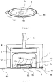
- FIG 4 shows a schematic representation of a gas-equilibrated, volatile-in-water probe provided by the invention wherein a gas sensor body 10 contains a removable and replaceable gas receiving and sensing member 11.
- a gas sensor body 10 contains a removable and replaceable gas receiving and sensing member 11.
- An example of such a sensor is the 16.6 mm x 20mm diameter miniature photoionisation detector (PID) manufactured by Ion Science Limited and containing an electrode pellet as described and claimed in our GB 2449664 B .
- PID miniature photoionisation detector
- PCB 4 is also in electrical contact with cable 5, as described in reference to corresponding components 3, 4 and 5 in Figure 1 .
- Gas sensing member 11 is approximately pellet shaped, and includes an orifice for receiving gas, 11a, on its outwardly facing major surface, 11b, opposing its other major surface proximal to the sensor body cavity (gas sensing chamber) 10b containing the gas sensing member 11.
- Surface 11b of the gas sensing member 11 is approximately co-planar with sensor body surface 10a, and also approximately co-planar with cradle wall flats 2a.
- Gas sensing member 11 is attached at annulus 11c to gas-porous or gas-permeable membrane 6 by means of an adhesive or ultrasonic welding of membrane portion 6a to the gas sensing member flat surface 11b close to the periphery of gas orifice 11a. It is preferable for the membrane portion 6a joined to gas sensing member portion 11c not to be porous or permeable to gas, either by virtue of an impermeable adhesive being applied to and impregnating the membrane, or by the membrane 6 and gas sensing member face 11b being welded at the point of fusion so as to form a seal that is neither porous nor appreciably permeable.
- the membrane 6 is also attached to cradle wall flats 2a by means of adhesive 13 at annulus 6b, thereby forming an entry point to a second gaseous enclosure 12 external of the gas-sensing chamber.
- the membrane is substantially porous or vapour-permeable over that portion overlaying gas orifice 11a and bounded by the impervious seal between annulus 6a and portion 11c.
- the membrane portion between annular seals 6a and 6b may or may not be porous or permeable according to the benefit conferred by enabling gaseous analyte gas irrigation at potential leak paths between probe members 10 and 11.
- the membrane 6 further may include a tab 6d for convenient removal of the membrane 6 after use.
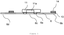
- Figure 5 shows a replaceable gas sensing sub-assembly comprising components 11 and 6 prior to their assembly in the probe shown schematically in figure 4 .
- This replaceable component includes a removable protective cover 14 to protect the adhesive portion of the membrane 6b.
- the sensor 1 In the case of a gas sensor containing an integral means of gas admittance, such as is described in Figure 1 , it is preferable for the sensor 1 to be removed from the cradle 2 over times of significant storage.
- the sensor is manually fitted in the cradle ensuring pins from the sensor 3 fit snugly into PCB platform 4.
- the covering 9 is removed from a disposable membrane assembly such as shown in Figure 2 , and placed over the cradle wall flats 2a and sensor face 1a to make a seal.
- the membrane and cradle to include means of co-alignment such as notches (not shown).
- the probe is now connected to a means of power supply and data communication via cable 5.
- the probe may be calibrated by placing a gas hood over the assembled probe, and presenting a suitable concentration of the analyte to the gas hood.
- the probe may be calibrated using an aqueous liquid, typically pure water, into which the gaseous analyte is dissolved.
- the former is generally preferable, and provides an advantage of using a gas-equilibrated, volatile-in-liquid detector over other volatile-in-water detection technologies. These previous detectors require aqueous reference samples, which are prone to loose the volatile as soon as their means of containment, typically a glass ampoule, is breached.
- the cable 5 connected to the probe is flexible and armoured or sheathed so as to provide protection when submerged in a watery fluid, perhaps under very adverse conditions.
- the probe may include additional members to ensure to protect the assembly from damage, particularly the probe itself. It is however deleterious for the membrane 6 to be appreciably obscured from the aqueous environment presented to it, insofar as free flow of fluids across it is needed for dynamic sensing.
- the removal of the sensor may benefit from additional cradle members, not shown in Figure 1 , which enable the cradle walls surrounding the circular or cylindrical section of the gas sensor to be partly dismantled.
- the sensor shown in Figure 4 is best stored with its removable components removed from the sensor cradle 2.
- the sensor may be manually assembled as described above, although in this case the membrane assembly shown in Figure 5 is affixed to the sensor cradle 2 only after careful orientation and assembly of gas sensor sub-components.
- a lamp is first inserted in the gas sensing member 11 opposite the membrane orifice 11a. Then the protective backing 14 to the adhesive section is removed. Then the membrane assembly is placed over the cradle wall flats 2a as shown in Figure 4 and pressed down to ensure a water tight seal.
- the probe shown in Figure 4 Following tests with the probe shown in Figure 4 , it is again advisable for the probe to be washed off in clean water and dried.
- the membrane 6 is peeled off cradle wall flats 2a.
- the entire sub-assembly shown in Figure 5 is removable and disposable, being a small, environmentally benign and modest cost item.
- the sensor body can then be removed and stored in a separate storage capsule or refitted with a new membrane assembly as depicted in Figure 5 , ready for subsequent use.
- the instrument is calibrated as described above.
- the use of a gas for calibration is a particular advantage where the PID is being used to trace a volatile to which PID responds, with reasonable assurance as to the presence of that volatile. For example, it might be calibrated with 1 ppm xylene in air, using Henry's Law to determine the equivalent xylene-in-water concentration.
- Possible applications of the invention include, for example, remediation of polluted water, monitoring of potable water, food and drink processing, and regulatory enforcement.
Landscapes
- Chemical & Material Sciences (AREA)
- Health & Medical Sciences (AREA)
- Life Sciences & Earth Sciences (AREA)
- Pathology (AREA)
- Physics & Mathematics (AREA)
- Analytical Chemistry (AREA)
- Biochemistry (AREA)
- General Health & Medical Sciences (AREA)
- General Physics & Mathematics (AREA)
- Immunology (AREA)
- Engineering & Computer Science (AREA)
- Food Science & Technology (AREA)
- Medicinal Chemistry (AREA)
- Chemical Kinetics & Catalysis (AREA)
- Electrochemistry (AREA)
- Toxicology (AREA)
- Combustion & Propulsion (AREA)
- Sampling And Sample Adjustment (AREA)
- Other Investigation Or Analysis Of Materials By Electrical Means (AREA)
- Investigating Or Analyzing Materials By The Use Of Fluid Adsorption Or Reactions (AREA)
Claims (15)
- Tête de capteur de détecteur par photo-ionisation (PID) destinée à être utilisée dans un détecteur de substances volatiles en milieu aqueux, ladite tête comprenant un détecteur par photo-ionisation miniature comprenant un corps de capteur de gaz (10) et un élément de détection de gaz remplaçable (11), ledit corps de capteur de gaz (10) ayant une cavité de corps de capteur définissant une chambre de détection de gaz (10b) contenant ledit élément de détection de gaz (11), la tête comprenant en outre une membrane poreuse ou perméable à la vapeur (6) formant un point d'entrée (6c) dans la chambre de détection de gaz autrement fermée, caractérisée en ce que le volume interne de la chambre de détection de gaz (10b) n'est pas supérieur à 100 mm3.
- Tête de capteur selon la revendication 1, la membrane (6) étant scellée à la périphérie d'un orifice de chambre (11a) au moyen d'un joint (7) d'orifice de chambre et formant un point d'entrée à une seconde enceinte gazeuse externe à la chambre de détection de gaz.
- Tête de capteur selon la revendication 1 ou 2, un joint d'enceinte périphérique (8) scellant la membrane (6) sur une paroi extérieure (2a) de la chambre de détection de gaz ou d'une enceinte périphérique.
- Tête de capteur selon la revendication 13, le joint de paroi externe (8) scellant au moyen d'un adhésif pelable.
- Tête de capteur selon la revendication 13 ou 14, les deux joints (7, 8) étant concentriques.
- Tête de capteur selon l'une quelconque des revendications précédentes dépendant de la revendication 2, l'orifice de chambre de détection de gaz (11a) étant dans une surface d'appui plane coplanaire avec la terminaison d'une paroi d'une enceinte périphérique (2).
- Tête de capteur selon l'une quelconque des revendications précédentes dépendant de la revendication 2, le joint (7) à la périphérie de l'orifice de chambre (11a) étant une barrière imperméable à la vapeur sur toute l'épaisseur de la membrane (6).
- Tête de capteur selon l'une quelconque des revendications précédentes dépendant de la revendication 2, le ou chaque joint (7, 8) étant un anneau.
- Tête de capteur selon l'une quelconque des revendications 1 à 8, la membrane (6) étant hydrophobe.
- Tête de capteur selon l'une quelconque des revendications 1 à 9, qui est détachable d'un ensemble supportant la tête de capteur.
- Tête de capteur selon l'une quelconque des revendications dépendant de la revendication 2, le joint (7) à la périphérie de l'orifice de chambre étant une soudure ou un adhésif imperméable pénétrant dans la membrane (6).
- Tête de capteur selon l'une quelconque des revendications 1 à 11, le capteur (10, 11) compris dans la tête de capteur comprenant une pluralité de contacts d'électrodes qui se trouvent dans un plan commun dans la chambre de détection de gaz.
- Tête de capteur selon la revendication 11 ou 12, la chambre de détection de gaz (10b) étant conçue de sorte à minimiser le volume mort en son sein.
- Tête de capteur selon l'une quelconque des revendications 1 à 13, les éléments du capteur étant à moins de 2 mm de la membrane (6) de sorte à réduire le temps de réponse du capteur.
- Détecteur de substance volatile dans un liquide à équilibre gazeux comprenant une tête de capteur selon l'une quelconque des revendications 1 à 14.
Applications Claiming Priority (2)
| Application Number | Priority Date | Filing Date | Title |
|---|---|---|---|
| GB1421306.0A GB2527867B (en) | 2014-12-01 | 2014-12-01 | Detection of organics in water |
| PCT/IB2015/059177 WO2016088008A1 (fr) | 2014-12-01 | 2015-11-27 | Système de détection par photo-ionisation pour matières organiques présentes dans l'eau |
Publications (3)
| Publication Number | Publication Date |
|---|---|
| EP3227676A1 EP3227676A1 (fr) | 2017-10-11 |
| EP3227676B1 true EP3227676B1 (fr) | 2018-10-31 |
| EP3227676B8 EP3227676B8 (fr) | 2019-02-27 |
Family
ID=52349738
Family Applications (1)
| Application Number | Title | Priority Date | Filing Date |
|---|---|---|---|
| EP15812886.8A Active EP3227676B8 (fr) | 2014-12-01 | 2015-11-27 | Système de détection par photo-ionisation pour matières organiques présentes dans l'eau |
Country Status (6)
| Country | Link |
|---|---|
| US (1) | US20170269049A1 (fr) |
| EP (1) | EP3227676B8 (fr) |
| JP (1) | JP6359773B2 (fr) |
| CN (1) | CN107209162B (fr) |
| GB (1) | GB2527867B (fr) |
| WO (1) | WO2016088008A1 (fr) |
Families Citing this family (3)
| Publication number | Priority date | Publication date | Assignee | Title |
|---|---|---|---|---|
| GB2537361B (en) | 2015-04-10 | 2017-05-03 | Ion Science Ltd | A Water Immersible Detector |
| GB2537881A (en) * | 2015-04-29 | 2016-11-02 | Ion Science Ltd | A method of operating a photoionisation detector to detect VOC's dissolved in water |
| WO2022130184A1 (fr) * | 2020-12-14 | 2022-06-23 | Molex, Llc | Détecteur de photo-ionisation et procédé associé d'activation |
Family Cites Families (14)
| Publication number | Priority date | Publication date | Assignee | Title |
|---|---|---|---|---|
| US4745796A (en) * | 1987-03-16 | 1988-05-24 | Honeywell Inc. | Membrane-selective vapor sensing |
| US4892383A (en) * | 1989-02-17 | 1990-01-09 | Fiberchem Inc. | Reservoir fiber optic chemical sensors |
| JP2810804B2 (ja) * | 1991-03-30 | 1998-10-15 | 日本電子株式会社 | 電子捕獲検出器 |
| AUPM707494A0 (en) * | 1994-07-26 | 1994-08-18 | Crc For Waste Management And Pollution Control Limited | A method and apparatus for environmental monitoring of low concentration levels of organic compounds |
| US5979219A (en) * | 1997-02-03 | 1999-11-09 | Sylvia Sellmer Wilsberg | Probe for measuring volatile components in an aqueous solution |
| US6272938B1 (en) * | 2000-04-07 | 2001-08-14 | General Electric Company | Monitoring of volatile organic compounds in groundwater with an in-situ sampling device |
| DE202004000570U1 (de) * | 2004-01-09 | 2004-03-18 | Ufz-Umweltforschungszentrum Leipzig-Halle Gmbh | Anordnung zur off site, on line und/oder in situ Messung organischer Substanzen in Flüssigkeiten und/oder Dämpfen |
| US8383046B1 (en) * | 2007-04-16 | 2013-02-26 | Murthy Tata | Analyzer apparatus for measuring dissolved volatile substances and method |
| GB2449664B (en) * | 2007-05-30 | 2011-12-14 | Ion Science Ltd | Electrode contact pellet and associated photoionisation detector assembly |
| US7930924B2 (en) * | 2007-09-28 | 2011-04-26 | Vancouver Island University | System for the online measurement of volatile and semi-volatile compounds and use thereof |
| JP5272466B2 (ja) * | 2008-03-21 | 2013-08-28 | 株式会社Ihi | 水中ロボット用溶存ガス濃度計測センサ装置 |
| JP5801398B2 (ja) * | 2010-08-19 | 2015-10-28 | インフィコン アーベー | ガスセンサハウジング |
| EP2825875B1 (fr) * | 2012-03-13 | 2019-05-08 | MKS Instruments, Inc. | Concentration d'un gaz à l'état de trace dans des pièges autorésonants de spectromètres de masse |
| CN104181284B (zh) * | 2014-07-11 | 2016-03-09 | 上海市政工程设计研究总院(集团)有限公司 | 一种土壤中挥发性有机物连续检测装置及其检测方法 |
-
2014
- 2014-12-01 GB GB1421306.0A patent/GB2527867B/en active Active
-
2015
- 2015-11-27 WO PCT/IB2015/059177 patent/WO2016088008A1/fr not_active Ceased
- 2015-11-27 CN CN201580075172.8A patent/CN107209162B/zh not_active Expired - Fee Related
- 2015-11-27 EP EP15812886.8A patent/EP3227676B8/fr active Active
- 2015-11-27 JP JP2017530201A patent/JP6359773B2/ja not_active Expired - Fee Related
- 2015-11-27 US US15/532,070 patent/US20170269049A1/en not_active Abandoned
Non-Patent Citations (1)
| Title |
|---|
| None * |
Also Published As
| Publication number | Publication date |
|---|---|
| GB201421306D0 (en) | 2015-01-14 |
| EP3227676B8 (fr) | 2019-02-27 |
| EP3227676A1 (fr) | 2017-10-11 |
| CN107209162B (zh) | 2019-12-13 |
| GB2527867B (en) | 2016-06-29 |
| WO2016088008A1 (fr) | 2016-06-09 |
| JP2017537323A (ja) | 2017-12-14 |
| GB2527867A (en) | 2016-01-06 |
| CN107209162A (zh) | 2017-09-26 |
| JP6359773B2 (ja) | 2018-07-18 |
| US20170269049A1 (en) | 2017-09-21 |
Similar Documents
| Publication | Publication Date | Title |
|---|---|---|
| Ohira et al. | A fiber optic sensor with a metal organic framework as a sensing material for trace levels of water in industrial gases | |
| CA2950795C (fr) | Methode et systeme d'extraction selective d'hydrogene gazeux destines a des applications d'analyse de gaz | |
| US20100005881A1 (en) | Protective device for a humidity sensor in an aggressive atmosphere | |
| US8537020B2 (en) | Visual indicator of gas sensor impairment | |
| EP3227676B1 (fr) | Système de détection par photo-ionisation pour matières organiques présentes dans l'eau | |
| EP1152238B1 (fr) | Appareil pour la détection des gaz combustibles | |
| US8916037B1 (en) | Instrument and method for measuring high concentrations of carbon monoxide in a gaseous sample | |
| JP2017133999A (ja) | 水質分析装置及び水質分析方法 | |
| GB2335277A (en) | Mounting sensor carrying wafer in water quality measuring apparatus | |
| US8383046B1 (en) | Analyzer apparatus for measuring dissolved volatile substances and method | |
| US20190242841A1 (en) | Hydrophobic and oleophobic cover for gas sensing module | |
| Cowie et al. | Membrane inlet ion trap mass spectrometry for the direct measurement of dissolved gases in ecological samples | |
| RU2568331C1 (ru) | Устройство для определения утечек взрывоопасных жидкостей на основе пьезосенсора | |
| US20230358703A1 (en) | Electrochemical sensor including a measuring cell and an oxidation component and process using such a sensor | |
| CN107636454A (zh) | 一种浸水式检测器 | |
| CN108139348B (zh) | 制冷剂分析仪及其使用方法 | |
| US20060120920A1 (en) | Hydrogen or helium sensor | |
| ITRM980584A1 (it) | Dispositivo per il campionamento diffusionale di vapori organici nello ambiente | |
| CA2265304A1 (fr) | Methode et instrument de detection et de mesure de faibles niveaux de gaz pouvant etre utilises dans la defense contre produits chimiques et la surveillance de l'environnement | |
| JP4954240B2 (ja) | 閉鎖されたセル内に検体を消費するセンサを有する電量検体検出装置 | |
| JP4010451B2 (ja) | 高濃度ガス測定用のアダプタ | |
| CZ24156U1 (cs) | Permeaění cela pro sledování permeace toxických látek bariérovými materiály | |
| Korotcenkov et al. | Chemical sensors selection and operation guide | |
| CN105445348A (zh) | 一种便携式二氧化碳气敏电极 | |
| US20050223777A1 (en) | Specimen holding plate for a gas permeability measuring apparatus |
Legal Events
| Date | Code | Title | Description |
|---|---|---|---|
| STAA | Information on the status of an ep patent application or granted ep patent |
Free format text: STATUS: THE INTERNATIONAL PUBLICATION HAS BEEN MADE |
|
| PUAI | Public reference made under article 153(3) epc to a published international application that has entered the european phase |
Free format text: ORIGINAL CODE: 0009012 |
|
| STAA | Information on the status of an ep patent application or granted ep patent |
Free format text: STATUS: REQUEST FOR EXAMINATION WAS MADE |
|
| 17P | Request for examination filed |
Effective date: 20170703 |
|
| AK | Designated contracting states |
Kind code of ref document: A1 Designated state(s): AL AT BE BG CH CY CZ DE DK EE ES FI FR GB GR HR HU IE IS IT LI LT LU LV MC MK MT NL NO PL PT RO RS SE SI SK SM TR |
|
| AX | Request for extension of the european patent |
Extension state: BA ME |
|
| DAV | Request for validation of the european patent (deleted) | ||
| DAX | Request for extension of the european patent (deleted) | ||
| GRAP | Despatch of communication of intention to grant a patent |
Free format text: ORIGINAL CODE: EPIDOSNIGR1 |
|
| STAA | Information on the status of an ep patent application or granted ep patent |
Free format text: STATUS: GRANT OF PATENT IS INTENDED |
|
| INTG | Intention to grant announced |
Effective date: 20180522 |
|
| GRAS | Grant fee paid |
Free format text: ORIGINAL CODE: EPIDOSNIGR3 |
|
| GRAA | (expected) grant |
Free format text: ORIGINAL CODE: 0009210 |
|
| STAA | Information on the status of an ep patent application or granted ep patent |
Free format text: STATUS: THE PATENT HAS BEEN GRANTED |
|
| AK | Designated contracting states |
Kind code of ref document: B1 Designated state(s): AL AT BE BG CH CY CZ DE DK EE ES FI FR GB GR HR HU IE IS IT LI LT LU LV MC MK MT NL NO PL PT RO RS SE SI SK SM TR |
|
| REG | Reference to a national code |
Ref country code: CH Ref legal event code: EP Ref country code: GB Ref legal event code: FG4D |
|
| REG | Reference to a national code |
Ref country code: AT Ref legal event code: REF Ref document number: 1060005 Country of ref document: AT Kind code of ref document: T Effective date: 20181115 |
|
| REG | Reference to a national code |
Ref country code: DE Ref legal event code: R096 Ref document number: 602015019269 Country of ref document: DE |
|
| REG | Reference to a national code |
Ref country code: IE Ref legal event code: FG4D |
|
| RAP2 | Party data changed (patent owner data changed or rights of a patent transferred) |
Owner name: ION SCIENCE LIMITED |
|
| REG | Reference to a national code |
Ref country code: CH Ref legal event code: PK Free format text: BERICHTIGUNG B8 |
|
| REG | Reference to a national code |
Ref country code: LT Ref legal event code: MG4D |
|
| REG | Reference to a national code |
Ref country code: NL Ref legal event code: FP |
|
| REG | Reference to a national code |
Ref country code: AT Ref legal event code: MK05 Ref document number: 1060005 Country of ref document: AT Kind code of ref document: T Effective date: 20181031 |
|
| PG25 | Lapsed in a contracting state [announced via postgrant information from national office to epo] |
Ref country code: FI Free format text: LAPSE BECAUSE OF FAILURE TO SUBMIT A TRANSLATION OF THE DESCRIPTION OR TO PAY THE FEE WITHIN THE PRESCRIBED TIME-LIMIT Effective date: 20181031 Ref country code: NO Free format text: LAPSE BECAUSE OF FAILURE TO SUBMIT A TRANSLATION OF THE DESCRIPTION OR TO PAY THE FEE WITHIN THE PRESCRIBED TIME-LIMIT Effective date: 20190131 Ref country code: IS Free format text: LAPSE BECAUSE OF FAILURE TO SUBMIT A TRANSLATION OF THE DESCRIPTION OR TO PAY THE FEE WITHIN THE PRESCRIBED TIME-LIMIT Effective date: 20190228 Ref country code: AT Free format text: LAPSE BECAUSE OF FAILURE TO SUBMIT A TRANSLATION OF THE DESCRIPTION OR TO PAY THE FEE WITHIN THE PRESCRIBED TIME-LIMIT Effective date: 20181031 Ref country code: LV Free format text: LAPSE BECAUSE OF FAILURE TO SUBMIT A TRANSLATION OF THE DESCRIPTION OR TO PAY THE FEE WITHIN THE PRESCRIBED TIME-LIMIT Effective date: 20181031 Ref country code: LT Free format text: LAPSE BECAUSE OF FAILURE TO SUBMIT A TRANSLATION OF THE DESCRIPTION OR TO PAY THE FEE WITHIN THE PRESCRIBED TIME-LIMIT Effective date: 20181031 Ref country code: ES Free format text: LAPSE BECAUSE OF FAILURE TO SUBMIT A TRANSLATION OF THE DESCRIPTION OR TO PAY THE FEE WITHIN THE PRESCRIBED TIME-LIMIT Effective date: 20181031 Ref country code: BG Free format text: LAPSE BECAUSE OF FAILURE TO SUBMIT A TRANSLATION OF THE DESCRIPTION OR TO PAY THE FEE WITHIN THE PRESCRIBED TIME-LIMIT Effective date: 20190131 Ref country code: PL Free format text: LAPSE BECAUSE OF FAILURE TO SUBMIT A TRANSLATION OF THE DESCRIPTION OR TO PAY THE FEE WITHIN THE PRESCRIBED TIME-LIMIT Effective date: 20181031 Ref country code: HR Free format text: LAPSE BECAUSE OF FAILURE TO SUBMIT A TRANSLATION OF THE DESCRIPTION OR TO PAY THE FEE WITHIN THE PRESCRIBED TIME-LIMIT Effective date: 20181031 |
|
| PG25 | Lapsed in a contracting state [announced via postgrant information from national office to epo] |
Ref country code: AL Free format text: LAPSE BECAUSE OF FAILURE TO SUBMIT A TRANSLATION OF THE DESCRIPTION OR TO PAY THE FEE WITHIN THE PRESCRIBED TIME-LIMIT Effective date: 20181031 Ref country code: GR Free format text: LAPSE BECAUSE OF FAILURE TO SUBMIT A TRANSLATION OF THE DESCRIPTION OR TO PAY THE FEE WITHIN THE PRESCRIBED TIME-LIMIT Effective date: 20190201 Ref country code: SE Free format text: LAPSE BECAUSE OF FAILURE TO SUBMIT A TRANSLATION OF THE DESCRIPTION OR TO PAY THE FEE WITHIN THE PRESCRIBED TIME-LIMIT Effective date: 20181031 Ref country code: RS Free format text: LAPSE BECAUSE OF FAILURE TO SUBMIT A TRANSLATION OF THE DESCRIPTION OR TO PAY THE FEE WITHIN THE PRESCRIBED TIME-LIMIT Effective date: 20181031 Ref country code: PT Free format text: LAPSE BECAUSE OF FAILURE TO SUBMIT A TRANSLATION OF THE DESCRIPTION OR TO PAY THE FEE WITHIN THE PRESCRIBED TIME-LIMIT Effective date: 20190301 |
|
| REG | Reference to a national code |
Ref country code: CH Ref legal event code: PL |
|
| PG25 | Lapsed in a contracting state [announced via postgrant information from national office to epo] |
Ref country code: CZ Free format text: LAPSE BECAUSE OF FAILURE TO SUBMIT A TRANSLATION OF THE DESCRIPTION OR TO PAY THE FEE WITHIN THE PRESCRIBED TIME-LIMIT Effective date: 20181031 Ref country code: DK Free format text: LAPSE BECAUSE OF FAILURE TO SUBMIT A TRANSLATION OF THE DESCRIPTION OR TO PAY THE FEE WITHIN THE PRESCRIBED TIME-LIMIT Effective date: 20181031 |
|
| REG | Reference to a national code |
Ref country code: DE Ref legal event code: R097 Ref document number: 602015019269 Country of ref document: DE |
|
| REG | Reference to a national code |
Ref country code: IE Ref legal event code: MM4A |
|
| PG25 | Lapsed in a contracting state [announced via postgrant information from national office to epo] |
Ref country code: EE Free format text: LAPSE BECAUSE OF FAILURE TO SUBMIT A TRANSLATION OF THE DESCRIPTION OR TO PAY THE FEE WITHIN THE PRESCRIBED TIME-LIMIT Effective date: 20181031 Ref country code: SM Free format text: LAPSE BECAUSE OF FAILURE TO SUBMIT A TRANSLATION OF THE DESCRIPTION OR TO PAY THE FEE WITHIN THE PRESCRIBED TIME-LIMIT Effective date: 20181031 Ref country code: LI Free format text: LAPSE BECAUSE OF NON-PAYMENT OF DUE FEES Effective date: 20181130 Ref country code: RO Free format text: LAPSE BECAUSE OF FAILURE TO SUBMIT A TRANSLATION OF THE DESCRIPTION OR TO PAY THE FEE WITHIN THE PRESCRIBED TIME-LIMIT Effective date: 20181031 Ref country code: CH Free format text: LAPSE BECAUSE OF NON-PAYMENT OF DUE FEES Effective date: 20181130 Ref country code: SK Free format text: LAPSE BECAUSE OF FAILURE TO SUBMIT A TRANSLATION OF THE DESCRIPTION OR TO PAY THE FEE WITHIN THE PRESCRIBED TIME-LIMIT Effective date: 20181031 Ref country code: MC Free format text: LAPSE BECAUSE OF FAILURE TO SUBMIT A TRANSLATION OF THE DESCRIPTION OR TO PAY THE FEE WITHIN THE PRESCRIBED TIME-LIMIT Effective date: 20181031 |
|
| PLBE | No opposition filed within time limit |
Free format text: ORIGINAL CODE: 0009261 |
|
| STAA | Information on the status of an ep patent application or granted ep patent |
Free format text: STATUS: NO OPPOSITION FILED WITHIN TIME LIMIT |
|
| 26N | No opposition filed |
Effective date: 20190801 |
|
| PG25 | Lapsed in a contracting state [announced via postgrant information from national office to epo] |
Ref country code: IE Free format text: LAPSE BECAUSE OF NON-PAYMENT OF DUE FEES Effective date: 20181127 Ref country code: SI Free format text: LAPSE BECAUSE OF FAILURE TO SUBMIT A TRANSLATION OF THE DESCRIPTION OR TO PAY THE FEE WITHIN THE PRESCRIBED TIME-LIMIT Effective date: 20181031 |
|
| PGFP | Annual fee paid to national office [announced via postgrant information from national office to epo] |
Ref country code: LU Payment date: 20191120 Year of fee payment: 5 |
|
| PG25 | Lapsed in a contracting state [announced via postgrant information from national office to epo] |
Ref country code: MT Free format text: LAPSE BECAUSE OF NON-PAYMENT OF DUE FEES Effective date: 20181127 |
|
| PGFP | Annual fee paid to national office [announced via postgrant information from national office to epo] |
Ref country code: DE Payment date: 20191121 Year of fee payment: 5 Ref country code: NL Payment date: 20191120 Year of fee payment: 5 |
|
| PGFP | Annual fee paid to national office [announced via postgrant information from national office to epo] |
Ref country code: FR Payment date: 20191120 Year of fee payment: 5 Ref country code: BE Payment date: 20191120 Year of fee payment: 5 Ref country code: IT Payment date: 20191128 Year of fee payment: 5 |
|
| PG25 | Lapsed in a contracting state [announced via postgrant information from national office to epo] |
Ref country code: TR Free format text: LAPSE BECAUSE OF FAILURE TO SUBMIT A TRANSLATION OF THE DESCRIPTION OR TO PAY THE FEE WITHIN THE PRESCRIBED TIME-LIMIT Effective date: 20181031 |
|
| PG25 | Lapsed in a contracting state [announced via postgrant information from national office to epo] |
Ref country code: MK Free format text: LAPSE BECAUSE OF NON-PAYMENT OF DUE FEES Effective date: 20181031 Ref country code: HU Free format text: LAPSE BECAUSE OF FAILURE TO SUBMIT A TRANSLATION OF THE DESCRIPTION OR TO PAY THE FEE WITHIN THE PRESCRIBED TIME-LIMIT; INVALID AB INITIO Effective date: 20151127 Ref country code: CY Free format text: LAPSE BECAUSE OF FAILURE TO SUBMIT A TRANSLATION OF THE DESCRIPTION OR TO PAY THE FEE WITHIN THE PRESCRIBED TIME-LIMIT Effective date: 20181031 |
|
| REG | Reference to a national code |
Ref country code: DE Ref legal event code: R119 Ref document number: 602015019269 Country of ref document: DE |
|
| REG | Reference to a national code |
Ref country code: NL Ref legal event code: MM Effective date: 20201201 |
|
| PG25 | Lapsed in a contracting state [announced via postgrant information from national office to epo] |
Ref country code: LU Free format text: LAPSE BECAUSE OF NON-PAYMENT OF DUE FEES Effective date: 20201127 |
|
| REG | Reference to a national code |
Ref country code: BE Ref legal event code: MM Effective date: 20201130 |
|
| PG25 | Lapsed in a contracting state [announced via postgrant information from national office to epo] |
Ref country code: NL Free format text: LAPSE BECAUSE OF NON-PAYMENT OF DUE FEES Effective date: 20201201 |
|
| PG25 | Lapsed in a contracting state [announced via postgrant information from national office to epo] |
Ref country code: IT Free format text: LAPSE BECAUSE OF NON-PAYMENT OF DUE FEES Effective date: 20201127 Ref country code: FR Free format text: LAPSE BECAUSE OF NON-PAYMENT OF DUE FEES Effective date: 20201130 |
|
| PG25 | Lapsed in a contracting state [announced via postgrant information from national office to epo] |
Ref country code: DE Free format text: LAPSE BECAUSE OF NON-PAYMENT OF DUE FEES Effective date: 20210601 |
|
| PG25 | Lapsed in a contracting state [announced via postgrant information from national office to epo] |
Ref country code: BE Free format text: LAPSE BECAUSE OF NON-PAYMENT OF DUE FEES Effective date: 20201130 |
|
| PGFP | Annual fee paid to national office [announced via postgrant information from national office to epo] |
Ref country code: GB Payment date: 20251119 Year of fee payment: 11 |