EP3227714B1 - Module de capteur de profondeur et procédé de détection de profondeur - Google Patents
Module de capteur de profondeur et procédé de détection de profondeur Download PDFInfo
- Publication number
- EP3227714B1 EP3227714B1 EP15866003.5A EP15866003A EP3227714B1 EP 3227714 B1 EP3227714 B1 EP 3227714B1 EP 15866003 A EP15866003 A EP 15866003A EP 3227714 B1 EP3227714 B1 EP 3227714B1
- Authority
- EP
- European Patent Office
- Prior art keywords
- light
- sensor module
- depth
- triangulation
- depth sensor
- Prior art date
- Legal status (The legal status is an assumption and is not a legal conclusion. Google has not performed a legal analysis and makes no representation as to the accuracy of the status listed.)
- Active
Links
Images




Classifications
-
- G—PHYSICS
- G01—MEASURING; TESTING
- G01S—RADIO DIRECTION-FINDING; RADIO NAVIGATION; DETERMINING DISTANCE OR VELOCITY BY USE OF RADIO WAVES; LOCATING OR PRESENCE-DETECTING BY USE OF THE REFLECTION OR RERADIATION OF RADIO WAVES; ANALOGOUS ARRANGEMENTS USING OTHER WAVES
- G01S17/00—Systems using the reflection or reradiation of electromagnetic waves other than radio waves, e.g. lidar systems
- G01S17/02—Systems using the reflection of electromagnetic waves other than radio waves
- G01S17/06—Systems determining position data of a target
- G01S17/46—Indirect determination of position data
- G01S17/48—Active triangulation systems, i.e. using the transmission and reflection of electromagnetic waves other than radio waves
-
- G—PHYSICS
- G01—MEASURING; TESTING
- G01S—RADIO DIRECTION-FINDING; RADIO NAVIGATION; DETERMINING DISTANCE OR VELOCITY BY USE OF RADIO WAVES; LOCATING OR PRESENCE-DETECTING BY USE OF THE REFLECTION OR RERADIATION OF RADIO WAVES; ANALOGOUS ARRANGEMENTS USING OTHER WAVES
- G01S17/00—Systems using the reflection or reradiation of electromagnetic waves other than radio waves, e.g. lidar systems
- G01S17/02—Systems using the reflection of electromagnetic waves other than radio waves
- G01S17/04—Systems determining the presence of a target
-
- G—PHYSICS
- G01—MEASURING; TESTING
- G01S—RADIO DIRECTION-FINDING; RADIO NAVIGATION; DETERMINING DISTANCE OR VELOCITY BY USE OF RADIO WAVES; LOCATING OR PRESENCE-DETECTING BY USE OF THE REFLECTION OR RERADIATION OF RADIO WAVES; ANALOGOUS ARRANGEMENTS USING OTHER WAVES
- G01S17/00—Systems using the reflection or reradiation of electromagnetic waves other than radio waves, e.g. lidar systems
- G01S17/02—Systems using the reflection of electromagnetic waves other than radio waves
- G01S17/06—Systems determining position data of a target
- G01S17/42—Simultaneous measurement of distance and other co-ordinates
-
- G—PHYSICS
- G01—MEASURING; TESTING
- G01S—RADIO DIRECTION-FINDING; RADIO NAVIGATION; DETERMINING DISTANCE OR VELOCITY BY USE OF RADIO WAVES; LOCATING OR PRESENCE-DETECTING BY USE OF THE REFLECTION OR RERADIATION OF RADIO WAVES; ANALOGOUS ARRANGEMENTS USING OTHER WAVES
- G01S17/00—Systems using the reflection or reradiation of electromagnetic waves other than radio waves, e.g. lidar systems
- G01S17/88—Lidar systems specially adapted for specific applications
- G01S17/89—Lidar systems specially adapted for specific applications for mapping or imaging
- G01S17/894—Three-dimensional [3D] imaging with simultaneous measurement of time-of-flight at a two-dimensional [2D] array of receiver pixels, e.g. time-of-flight cameras or flash lidar
-
- G—PHYSICS
- G01—MEASURING; TESTING
- G01S—RADIO DIRECTION-FINDING; RADIO NAVIGATION; DETERMINING DISTANCE OR VELOCITY BY USE OF RADIO WAVES; LOCATING OR PRESENCE-DETECTING BY USE OF THE REFLECTION OR RERADIATION OF RADIO WAVES; ANALOGOUS ARRANGEMENTS USING OTHER WAVES
- G01S7/00—Details of systems according to groups G01S13/00, G01S15/00, G01S17/00
- G01S7/48—Details of systems according to groups G01S13/00, G01S15/00, G01S17/00 of systems according to group G01S17/00
- G01S7/481—Constructional features, e.g. arrangements of optical elements
- G01S7/4811—Constructional features, e.g. arrangements of optical elements common to transmitter and receiver
- G01S7/4813—Housing arrangements
-
- G—PHYSICS
- G01—MEASURING; TESTING
- G01S—RADIO DIRECTION-FINDING; RADIO NAVIGATION; DETERMINING DISTANCE OR VELOCITY BY USE OF RADIO WAVES; LOCATING OR PRESENCE-DETECTING BY USE OF THE REFLECTION OR RERADIATION OF RADIO WAVES; ANALOGOUS ARRANGEMENTS USING OTHER WAVES
- G01S7/00—Details of systems according to groups G01S13/00, G01S15/00, G01S17/00
- G01S7/48—Details of systems according to groups G01S13/00, G01S15/00, G01S17/00 of systems according to group G01S17/00
- G01S7/481—Constructional features, e.g. arrangements of optical elements
- G01S7/4814—Constructional features, e.g. arrangements of optical elements of transmitters alone
- G01S7/4815—Constructional features, e.g. arrangements of optical elements of transmitters alone using multiple transmitters
-
- G—PHYSICS
- G01—MEASURING; TESTING
- G01S—RADIO DIRECTION-FINDING; RADIO NAVIGATION; DETERMINING DISTANCE OR VELOCITY BY USE OF RADIO WAVES; LOCATING OR PRESENCE-DETECTING BY USE OF THE REFLECTION OR RERADIATION OF RADIO WAVES; ANALOGOUS ARRANGEMENTS USING OTHER WAVES
- G01S7/00—Details of systems according to groups G01S13/00, G01S15/00, G01S17/00
- G01S7/48—Details of systems according to groups G01S13/00, G01S15/00, G01S17/00 of systems according to group G01S17/00
- G01S7/481—Constructional features, e.g. arrangements of optical elements
- G01S7/4816—Constructional features, e.g. arrangements of optical elements of receivers alone
-
- G—PHYSICS
- G01—MEASURING; TESTING
- G01S—RADIO DIRECTION-FINDING; RADIO NAVIGATION; DETERMINING DISTANCE OR VELOCITY BY USE OF RADIO WAVES; LOCATING OR PRESENCE-DETECTING BY USE OF THE REFLECTION OR RERADIATION OF RADIO WAVES; ANALOGOUS ARRANGEMENTS USING OTHER WAVES
- G01S7/00—Details of systems according to groups G01S13/00, G01S15/00, G01S17/00
- G01S7/48—Details of systems according to groups G01S13/00, G01S15/00, G01S17/00 of systems according to group G01S17/00
- G01S7/491—Details of non-pulse systems
- G01S7/4912—Receivers
- G01S7/4913—Circuits for detection, sampling, integration or read-out
-
- G—PHYSICS
- G01—MEASURING; TESTING
- G01S—RADIO DIRECTION-FINDING; RADIO NAVIGATION; DETERMINING DISTANCE OR VELOCITY BY USE OF RADIO WAVES; LOCATING OR PRESENCE-DETECTING BY USE OF THE REFLECTION OR RERADIATION OF RADIO WAVES; ANALOGOUS ARRANGEMENTS USING OTHER WAVES
- G01S7/00—Details of systems according to groups G01S13/00, G01S15/00, G01S17/00
- G01S7/48—Details of systems according to groups G01S13/00, G01S15/00, G01S17/00 of systems according to group G01S17/00
- G01S7/497—Means for monitoring or calibrating
-
- G—PHYSICS
- G01—MEASURING; TESTING
- G01S—RADIO DIRECTION-FINDING; RADIO NAVIGATION; DETERMINING DISTANCE OR VELOCITY BY USE OF RADIO WAVES; LOCATING OR PRESENCE-DETECTING BY USE OF THE REFLECTION OR RERADIATION OF RADIO WAVES; ANALOGOUS ARRANGEMENTS USING OTHER WAVES
- G01S17/00—Systems using the reflection or reradiation of electromagnetic waves other than radio waves, e.g. lidar systems
- G01S17/02—Systems using the reflection of electromagnetic waves other than radio waves
- G01S17/06—Systems determining position data of a target
- G01S17/08—Systems determining position data of a target for measuring distance only
- G01S17/10—Systems determining position data of a target for measuring distance only using transmission of interrupted, pulse-modulated waves
-
- G—PHYSICS
- G01—MEASURING; TESTING
- G01S—RADIO DIRECTION-FINDING; RADIO NAVIGATION; DETERMINING DISTANCE OR VELOCITY BY USE OF RADIO WAVES; LOCATING OR PRESENCE-DETECTING BY USE OF THE REFLECTION OR RERADIATION OF RADIO WAVES; ANALOGOUS ARRANGEMENTS USING OTHER WAVES
- G01S17/00—Systems using the reflection or reradiation of electromagnetic waves other than radio waves, e.g. lidar systems
- G01S17/02—Systems using the reflection of electromagnetic waves other than radio waves
- G01S17/06—Systems determining position data of a target
- G01S17/08—Systems determining position data of a target for measuring distance only
- G01S17/32—Systems determining position data of a target for measuring distance only using transmission of continuous waves, whether amplitude-, frequency-, or phase-modulated, or unmodulated
- G01S17/36—Systems determining position data of a target for measuring distance only using transmission of continuous waves, whether amplitude-, frequency-, or phase-modulated, or unmodulated with phase comparison between the received signal and the contemporaneously transmitted signal
Definitions
- the present invention relates to an optical depth sensor module and depth sensing system.
- the optical depth sensor module can be used as proximity sensor with enhanced functionalities.
- Optical proximity sensors as typically used in mobile phones emit a light signal and measure the back-reflected light intensity. Based on the measured back-reflected light intensity, the presence of an object is derived. Most of the proximity sensors include a single light source and a single photo detector in the same package. Such systems have been presented e.g. by Fadell et al. in US patent application US 2008/0006762 A1 . Different ways to integrate an optical proximity sensor into a small module based on emitting light and measuring the back-reflected light signal from an object have been presented by Campbell in US patent US 8,748,856 B2 and by Rudmann in US patent US 8'791 '489B2 .
- a first proximity sensor based on a depth sensor module called time-of-flight depth sensor based on single photon avalanche diodes (SPAD) has been presented by Baxter in US 8'610'043B2.
- such indirect time-of-flight sensors are based on demodulation pixels that are capable of sampling the impinging light at several points in time and based on those samplings, the phase, the amplitude and the offset information of the impinging light can be deduced.
- the future depth sensor module in the proximity sensor application not only measures the depth of a single point in space, but preferably supplies a two-dimensional depth map in a given field of view measured by an array of depth measuring pixels.
- the availability of a depth map supplied by the proximity sensor in a mobile phone, even if only 10 x 10 pixels or less, will enable the introduction of completely new functionalities such as gesture recognition for touch free operation of devices, e.g. as presented in US patent application US 2013/0179162A1 .
- a measurement sensor comprising a PSD (Position Sensing Device) as an optoelectronic receiver, a transmitter for generating a spot an optics for reproducing said spot on the PSD and means for processing output signals generated by said PSD and for controlling the said transmitter depending on the processed output signals in order to measure the distance between the target and the sensor by a triangulation technique is disclosed.
- the transmitter comprises at least two optoelectronic signal sources for projecting at least two spots independent from each other on a target, the means comprising a digitally controlled potentiometer for balancing the output signals and a digital processor adapted for controlling the potentiometer.
- the depth sensor module can include a light emitting part for illuminating objects and a light detector part, the light emitting part and the light detector part being spatially offset in the direction of a triangulation baseline.
- the light emitting part can include at least two light sources spatially offset in the direction of the triangulation baseline, wherein the light detector part is configured to acquire light and to provide along the direction of the triangulation baseline an intensity distribution of the acquired light.
- the intensity distribution of the acquired light stems from two different light sources accordingly. Knowing the spatial offsets between the light sources and the light detector part enables a triangulation, which enables a depth estimation, namely an estimation of the distance between the depth sensor module and the object.
- the depth sensor module is configured to perform a triangulation evaluation using the intensity distribution of the acquired light.
- a triangulation evaluation using the intensity distribution of the acquired light.
- the depth sensor module can be operable to carry out triangulation calculations in dependence of the intensity distribution and, optionally, also in dependence of spatial offsets between the light sources and pixels of the light detecting part.
- the depth sensor module is configured to enable a triangulation evaluation by determining a zero-crossing point of the difference between two intensity distributions of acquired light originating from two of the at least two light sources of the light emitting part.
- the triangulation-based evaluation of the distance of the object based on the differential signals of the intensity distribution of acquired light originating from the at least two different light sources offset spatially in the direction of triangulation baseline enables to reduce typical prior art triangulation requirements of emitting well focused light points or structures to guarantee for precise lateral resolution.
- the light emitter part can emit non-structured light such as diffuse light generated by each of the at least two light sources.
- the light can have rather wide cones of light (emission cones) instead of having to exhibit sharp points, lines or structures as it is typically requested by prior art triangulation systems.
- the evaluation of the triangulation system based on the signal difference becomes straightforward, even when the cones of lights emitted are not well structured.
- the setup of the light emitting part is simplified, because in many cases light sources already emit cones of light and thus (more or less) unstructured light.
- the depth sensor modules can be devoid any projecting optics.
- the evaluation of the differential signal along the direction of the triangulation baseline captured by the light detection part can result in an increased stability of the depth sensor measurements in terms of susceptibility to manufacturing tolerances, thermal drifts, aging artefacts and so on.
- the at least two light sources are configured to be controlled individually.
- An individual control of the at least two light sources enables to alternate the light emission by the different light sources.
- the first light source can be turned on while the second light source is turned off.
- the back-reflected light is captured by the light detection part, and a first intensity distribution is measured.
- the first light source is turned off and the second light source is turned on.
- the back-reflected light is captured by the light detection part, and a second intensity distribution is measured.
- a zero-crossing point along the direction of the triangulation baseline can be determined.
- the evaluation of the zero-crossing point directly refers (relates) to the depth of the object.
- the individual control of the at least two light sources enables to alternate the light emission of the at least two light sources during a single exposure.
- the demodulation pixels can be synchronized with the alternating control of the at least two light sources.
- the demodulation pixels are capable to transfer photo-generated charges generated when the first light source is turned on into first storages of the pixels, to transfer photo-generated charges generated when a second light source is turned on into second storages and so on if further light sources and further storages are provided. This procedure can be repeated many times during a single exposure and the photo-generated charges can be integrated in the storages of the demodulation pixels before reading out the values and performing the evaluation.
- state-of-the-art demodulation pixels include a background light removal circuitry or a signal subtraction circuitry, which can further simplify evaluation and enhance the dynamic range.
- the at least two light sources are arranged on a single die. E.g., they can be included in a single die.
- the integration of the at least two light sources on a single die enables to reduce space and costs, both important criteria for high volume, low costs application of a proximity sensor. Further, having the at least two light sources on a single die can reduce the likelihood of possible performance discrepancies between the at least two light sources.
- a first and a second of the at least two light sources are operable to emit a first light beam having a first light intensity distribution and a second light beam having a second light intensity distribution, respectively.
- the first and second light intensity distributions can be mutually symmetric with respect to a plane aligned perpendicularly to the triangulation baseline.
- the light emitting part is operable to alternatingly illuminate objects with a first one of the at least two light sources while not illuminating the objects with a second one of the at least two light sources; and illuminate objects with a second one of the at least two light sources while not illuminating the objects with a first one of the at least two light sources.
- the light detector part includes an image sensor configured to acquire light.
- the implementation of an image sensor in the light detector part enables the acquisition of a full two-dimensional image of intensity distributions.
- a first image is captured while a first light source is turned on and a second light source is turned off
- a second image is captured when a second light source is turned on and a first light source is turned off
- the two intensity distribution images can be subtracted from each other. Possibly, a zero-crossing point can then be found on every pixel line of the image sensor in the direction of the triangulation baseline. Having e.g.
- an image sensor with a resolution of m x n pixels, where n is the number of pixels in along the direction of the triangulation baseline and m along the orthogonal direction (orthogonal to the triangulation baseline), m zero-crossing points representing distances to the object may be detected. In other words, a full depth line can be measured.
- the image sensor includes or even is a time-of-flight sensor.
- the time-of-flight sensor is capable of demodulating the incoming light. Synchronizing it with the at least two light sources enables to perform triangulation measurements as herein described. State-of-the-art time-of-flight pixels further enable to suppress background light. This means the pixels are capable of subtracting signals on the pixel and therefore increase the dynamic range of the system.
- the depth sensor module is configured to enable time-of-flight measurements.
- each of the time-of-flight pixels can be used to determine a depth using the described triangulation method, too. Having e.g. an image sensor with m x n time-of-flight pixels, where n is the number of pixels along the direction of the triangulation baseline and m along the orthogonal direction, m zero-crossing points representing distances to the object can be detected. Further, since each of the m x n time-of-flight pixels of the image sensor is capable of rendering a depth value, a full depth map can be generated.
- the depth data derived by the triangulation method can be used to calibrate the time-of-flight depth map, while the time-of-flight depth map generates a full two-dimensional depth map.
- the light emitting part includes at least one optical feedback pixel.
- the at least one optical feedback pixel can be used to control the power of the at least two light sources.
- the at least one optical feedback pixel can be used to further calibrate the depth measurement accomplished using the time-of-flight pixels of the image sensor.
- the at least one optical feedback pixel is arranged on (e.g., included in) the same die as the pixel field.
- the pixels can have different sensitivities to cover a bigger dynamic range. If there are several optical feedback pixels, the individual results of the optical feedback pixels can be averaged or combined to improve a signal-to-noise ratio of the optical feedback results.
- the depth sensor module can be configured as a proximity sensor.
- the depth sensor module can be used as a (possibly simple) proximity sensor.
- the method can have properties corresponding to properties of any of the described sensor modules. It can be, e.g., a depth sensing method using a depth sensor having a light detector part and a light emitting part, the light emitting part and the light detector part being spatially offset in the direction of a triangulation baseline.
- the light emitting part includes at least two light sources spatially offset in the direction of the triangulation baseline.
- the depth sensing method comprises the steps of: acquiring light using the light detector part, and providing in the direction of the triangulation baseline an intensity distribution of the acquired light. In a variant, a triangulation evaluation using the intensity distribution of the acquired light is performed.
- a triangulation evaluation is performed by determining a zero-crossing point of the difference between two intensity distributions of acquired light originating from two of the at least two light sources of the light emitting part.
- the at least two light sources of the light emitting part are controlled individually.
- the light is acquired using an image sensor included in the detector part.
- a time-of-f light measurement is performed.
- an optical-feedback measurement is performed using at least one optical feedback pixel in the light emitting part.
- the depth sensor module is used as a proximity sensor.
- Prior art proximity sensor modules include a light source and a photo detector. Light is emitted by the light source and detected by the photo detector. In case some light of the emitted light source is reflected back to the proximity sensor and detected by the photo detector, it is assumed that an object is in front of the proximity sensor. Typically simple signal thresholding is performed to decide whether there is an object in close range or not.
- Triangulation is the process of determining the location (or distance) of a point in a scene. At either end of a baseline, the angles between the point and the baseline are measured or known, respectively. Using trigonometric formulas, the distance between the triangulation baseline and the point can be calculated.
- Figs. 1 a-c show a depth sensor module 2.
- Fig. 1 a sketches the depth sensor module in a 3-D view
- Fig. 1 b shows a top view in the horizontal cross section
- Fig. 1 c a side view in the vertical cross section.
- the depth sensor module 2 includes a light emitting part 30 and a light detection part 20.
- the light emitting part 30 and the light detection part 20 are spatially offset in the direction of the triangulation baseline 15.
- the light emitting part 30 includes at least two light sources 32a and 32b which are spatially offset along the direction of the triangulation baseline 15. The two light sources may be on the same light emitting die 32 as illustrated in the drawing.
- the two light sources 32a and 32b are, e.g., vertical cavity surface emitting laser diodes (VCSEL) on the same light emitting die 32.
- the light emitting die 32 includes two pads to individually control the two light sources 32a and 32b from the outside, corresponding to a possible embodiment.
- the two light sources 32a and 32b are spatially offset along the direction of the triangulation baseline 15.
- the light generated by the first light source 32a and the second light source 32b is projected into the scene onto the object 1 (cf. Fig. 2a ) by the projecting optics 33.
- the back-reflected light will be imaged by the imaging optics 23 onto a pixel field 211of the image sensor 210.
- the image sensor 210 includes the pixel field 211, but further may also include one or more of driving circuitries and further also includes one or more of control and evaluation circuitries. However, any or all of those circuitries may also be placed outside the image sensor 210, e.g., in a separate chip.
- Fig. 2a-c illustrate the depth sensor module 2 of Fig. 1 , but with a first light beam 35a and a second light beam 35b are shown in the drawing of Fig. 2a for illustration purposes.
- the light power of the first light beam 35a can be the same as the light power of the second light beam 35b, and the two light beams can be symmetric along a zero-crossing axis 38 (or more precisely: zero-crossing surface/plane in a three-dimensional space).
- the object 1 is illuminated by the first light beam 35a and the second light beam 35b individually.
- the image sensor 210 is used to acquire the light reflected by the object 1 illuminated by the first light beam 35a and the second light beam 35b.
- the intensity distribution of the light acquired by the image sensor 210 along the direction of the triangulation baseline 15 is plotted in the drawing of Fig. 2b , namely the intensity distribution 35a' of the acquired light during illumination by the first light beam 35a and the intensity distribution 35b' of the acquired light during illumination by the second light beam 35b.
- the differential signal 35a'-35b' namely the intensity distribution 35b' of the acquired light during illumination by the second light beam 35b subtracted from the intensity distribution 35a' of the acquired light during illumination by the first light beam 35a, is plotted in Fig. 2c .
- the first light source 32a and the second light source 32b may be switched on and off in alternating series.
- the second light source 32b in combination with the projecting optics 33 generates a second light beam 35b, which is offset or tilted along direction of the triangulation baseline 15 with respect to the first light beam 35a.
- the two light sources 32a and 32b are simply offset on the same light emitting die 32 and the projecting optics 33 in front of the two light sources 32a and 32b further modifies the shape of the two light beams 35a and 35b in order to enhance the detectability of the zero-crossing point.
- the zero-crossing axis 38 represents the positions where the power of the first light beam 35a is equivalent to the power of the second light beam 35b.
- the projecting optics 33 may consist of several optical elements such as lenses and/or diffractive optical elements, or may be built by a single lens element or may even consist of a simple glass.
- the resulting differential signal 35a'-35b' will show the zero-crossing point 39 (cf. Figs. 3a-c ) along the direction of the triangulation baseline 15 where the intensity of the reflected light from the object 1 back to the light detector part 20 during illumination by the first light beam 35a is equal to the intensity of the reflected light from the object 1 back to the light detector part 20 during illumination by the second light beam 35b.
- the zero-crossing point 39 on the pixel field 211 on the image sensor 210 can be used to triangulate, which means, the location of the zero-crossing point 39 relates to and allows to determine the distance of the object 1 to the depth sensor module 2.
- the drawing in Fig. 2b shows the intensity distribution of the acquired light during illumination by the first light beam 35a and the intensity distribution of the acquired light during illumination by the second light beam 35b along the direction of the triangulation baseline 15.
- Fig. 2c illustrates the difference of the signal generated by the back-reflection of the first light beam 35a and the back-reflection of the second light beam 35b.
- Varying the power ratio of the two light sources 32a and 32b enables to tilt the zero-crossing axis 38 back and forth along the direction of the triangulation baseline 15. This may give certain flexibility in steering the zero-crossing axis.
- the proposed zero-crossing triangulation method is significantly more stable with respect to stray light originating, e.g., from reflections from dirt or dust particles appearing in front of the depth sensor module 2.
- the signals of the time-of-flight image sensor can be used to first detect and localize the zero-crossing point, and, thus to reliably measure a first distance.
- the stable zero-crossing triangulation-based distance measurement can be used to calibrate the depth map generated by the time-of-flight measurements of each of the pixels of the time-of-flight image sensor.
- the zero-crossing triangulation-based calibration of the time-of-flight depth map can be done on-the-fly as long as the zero-crossing point 39 is imaged at least partly from the object 1 onto the pixel field 211 by the imaging optics 23. In case object 1 is not always imaged onto the pixel field 211 by the imaging optics 23, the calibration can at least be updated whenever the zero-crossing point becomes visible on the pixel field 211.
- the detection of the position of the zero-crossing point 39 enables to correct for all stray light issues on the time-of-flight depth measurements.
- each of the pixels typically includes or even consists of two storage nodes.
- demodulation pixel architectures have been presented in patents US5'856'667 , EP1009984B1 , EP1513202B1 and US7'884'310B2 .
- the photo-generated charges when the first light source 32a is turned on can be stored on the first storage nodes of the pixels, and the photo-generated charges when the second light source 32b is turned on can be stored in the second storage nodes of the pixels.
- the first and second light sources 32a, 32b can be alternately turned on and off during an exposure, while synchronizing them with the switches in the demodulation pixels steering the photo-generated charges to either the first storage nodes of the pixels or the second storage nodes of the pixels, respectively.
- having a background removal circuitry on the demodulation pixels enables to get rid of all the charges generated by background light.
- Such background removal circuitries for demodulation pixels have been presented in PCT publication WO2009135952A2 and in the US patents US7574190B2 and US7897928B2 .
- the removal of a common mode signal level on the different storage nodes of each pixel can drastically increase the dynamic range of the depth sensor module 2.
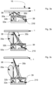
- Figs. 3a to c illustrate an exemplary embodiment of the zero-crossing triangulation approach.
- a first light source 32a emits a first light beam 35a
- a second light source 32b emits a second light beam 35b. Both light beams are typically transformed by projecting optics 33. But in instances, projection optics can also be dispensed with.
- the back-reflected light beams from object 1 are imaged by the (generally optional) imaging optics 23 (cf. Fig. 2a ) onto the pixel field 211 of the image sensor 210.
- the first and second light sources are alternately turned on and off.
- the zero-crossing point 39 in the differential image is imaged by the imaging optics 23 to a position close to the right edge of the pixel field 211 on the image sensor 210.
- the zero-crossing point 39 of the differential image moves to the left on the pixel field 211 of the image sensor 210, while at an even longer distance of the object 1 to the depth sensor module 2, as illustrated in Fig. 3c , the zero-crossing point 39 of the differential image even further moves to the left on the pixel field 211 of the image sensor 210.
- the zero-crossing point 39 in the difference of the images captured when the first light source 32a is turned on and when the second light source 32b is turned on can be used for triangulation purposes.
- the image difference can be generated e.g. by sequentially capturing two images, namely one image with the first light source 32a turned on and one with the second light source 32b turned on, and subtract one from the other.
- demodulation pixels are light sensing pixels in the pixel field 211.
- demodulation pixels have been presented in patents US5'856'667 , EP1009984B1 , EP1513202B1 and US7'884'310B2.
- Demodulation pixels can have two storage sites on each pixel. The steering of the photo-generated charges from the photo-sensitive area to one of the two charge storages can be done in synchronization with the alternate control of the first light source 32a and the second light source 32b.
- the first storage nodes of each pixel of the pixel field 211 store the photo-generated charges generated while the first light source 32a is turned on, and the second storage nodes of each pixel of the pixel field 211 store photo-generated charges while the second light source 32b is turned on.
- More sophisticated demodulation pixels already include subtracting circuitry in each pixel. This enables a better background light signal removal and therefore a more robust system.
- the raw sampling data - possibly in combination with the on-pixel background removal circuitry of the time-of-flight pixels - can be used to find the zero-crossing point 39 and determine depths, based on the localization of the zero-crossing point on the pixel field 211.
- the travel times of the emitted light from the depth sensor module 2 to the object 1 and back measured by the time-of-flight pixels in the pixel field 211 on the image sensor 210 can further enable to build a full two-dimensional depth map.
- the depth measurements derived by the zero-crossing triangulation approach can be used to calibrate the two-dimensional depth map derived from the time-of-flight based depth measurements.
- the calibration performed using the zero-crossing triangulation approach improves the stability and robustness of the depth sensor module in terms of stray light, thermal drifts and many others artefacts.
- Time-of-flight pixels integrated in the image sensor 210 may be demodulation pixels as used in indirect (phase measurement based) time-of-flight measurement systems or direct (single photon avalanche detection-based) time-of-flight measurement systems.
- the calibration evaluation based on the triangulation approach can be carried out with every single depth measurement, or may be done from time to time, or can be done simply whenever required.
- Figs. 4a-c show another embodiment.
- Fig. 4a is a three-dimensional drawing of the depth sensor module 2.
- Fig. 4b shows the horizontal cross-section B-B,
- Fig. 4c the vertical cross-section A-A.
- the depth measurement principle of the depth sensor module 2 is the same as the one sketched in Fig. 1 a to c.
- this embodiment further includes optical feedback pixels 212 in the light emitting part 30.
- optical feedback pixels 212 there is not only one optical feedback pixel but a full array of optical feedback pixels, in order to increase signal-to-noise ratio of the measured feedback.
- the different optical feedback pixels also may have different sensitivities or different exposure times to increase the dynamic range of the optical feedback operation.
- the optical feedback pixels can be used to measure and then control the emitted light power of the first light source 32a and the second light source 32b.
- the optical feedback pixels 212 are time-of-flight pixels, the optical feedback pixels can also be used to calibrate for the time-of-flight measurements.
- the optical feedback pixels can be on the same integrated image sensor 210 than the pixel field 211, but they can also be on two separate chips.
- the optical feedback pixels are used to be used as feedback pixels to adjust emitted light intensities, calibrate for intensities, adjust phase delay, calibrate for phase delays, or detect dirt/dust.
- Fast intensity variations may be caused by temperature changes or can mean deposition/removal of dirt/dust, while slow intensity variations may be consequences of aging.
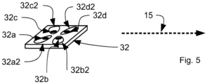
- Fig. 5 shows a sketch of a light emitting die 32, which includes four different light sources 32a, 32b, 32c, and 32d.
- Each of the four light sources 32a to 32d can be controlled individually.
- each of the four light sources 32a, 32b, 32c, and 32d has its own contact pad 32a2, 32b2, 32c2, and 32d2, respectively, and therefore full driving control from the outside of the light emitting die 32 is possible.
- the availability of more than two light sources in the light emitting part 30 as sketched in Fig. 5 enables to apply more sophisticated calibration schemes and renders the system more stable in terms of stray light e.g. caused by dirt or dust particles, deflecting parts of the emitted light beams directly back into the light detector part 20.
- Fig. 6 shows only the light emitting part 30 of an embodiment of the depth sensor module 2, with a cover glass 40 in front of the depth sensor module 2.
- the two light sources 32a and 32b are spatially offset in the triangulation direction 15.
- the light emitted by the two light sources 32a and 32b is transformed by the projecting optics 33 as such that the light distribution of the first light beam 32a and the second light beam 32b are as equal as possible at the area, where typically dirt or dust may reflect stray light into the light detector part 20.
- the back-scattered stray light originating from the first light beam 35a and the back-scatted stray light originating from the second light beam 35b will be the same or at least very similar.
- the two light beams can slightly drift apart in order to produce a clean depth dependant zero-crossing on the pixel field 211 on the image sensor 210.
Landscapes
- Engineering & Computer Science (AREA)
- Physics & Mathematics (AREA)
- Computer Networks & Wireless Communication (AREA)
- General Physics & Mathematics (AREA)
- Radar, Positioning & Navigation (AREA)
- Remote Sensing (AREA)
- Electromagnetism (AREA)
- Measurement Of Optical Distance (AREA)
- Length Measuring Devices By Optical Means (AREA)
Claims (15)
- Module de capteur de profondeur (2) comprenant une partie électroluminescente (30) pour éclairer un objet (1) et une partie détectrice de lumière (20), la partie électroluminescente (30) et la partie détectrice de lumière (20) étant décalées dans l'espace dans la direction d'une ligne de base de triangulation (15), dans lequel la partie électroluminescente (30) comprend au moins deux sources de lumière (32a, 32b) décalées dans l'espace dans la direction de la ligne de base de triangulation (15) et disposées sur une seule puce, dans lequel la partie détectrice de lumière (20) est configurée pour acquérir de la lumière et pour fournir, le long de la direction de la ligne de base de triangulation (15), une distribution d'intensité de la lumière acquise,
dans lequel le module de capteur de profondeur (2) comprend en outre :des circuits de commande et d'évaluation fonctionnant pour permettre une évaluation de triangulation en déterminant un point de passage par zéro (39) qui est une différence entre deux distributions d'intensité de lumière acquise provenant des au moins deux sources de lumière (32a, 32b) de la partie électroluminescente (30) et fonctionnant pour effectuer l'évaluation de triangulation sur la base du point de passage par zéro déterminé ; etun ensemble complet de pixels de rétroaction optique pour augmenter le rapport signal/bruit d'une rétroaction mesurée ;dans lequel les pixels de rétroaction optique (212) sont utilisés comme des pixels de rétroaction (212) pour ajuster des intensités de lumière émise. - Module de capteur de profondeur (2) selon la revendication 1, dans lequel les pixels de rétroaction optique (212) sont des pixels à temps de vol.
- Module de capteur de profondeur (2) selon les revendications 1 à 2, dans lequel le module de capteur de profondeur (2) est configuré pour effectuer l'évaluation de triangulation en utilisant la distribution d'intensité de la lumière acquise.
- Module de capteur de profondeur (2) selon l'une des revendications 1 à 3, dans lequel une première et une deuxième des au moins deux sources de lumière (32a, 32b) fonctionnent pour émettre respectivement un premier faisceau lumineux ayant une première distribution d'intensité de lumière et un deuxième faisceau lumineux ayant une deuxième distribution d'intensité de lumière, dans lequel les première et deuxième distributions d'intensité de lumière sont mutuellement symétriques par rapport à un plan aligné perpendiculairement à la ligne de base de triangulation.
- Module de capteur de profondeur (2) selon l'une des revendications 1 à 4, dans lequel la partie électroluminescente (30) peut fonctionner pour, en alternance,- éclairer l'objet avec la première (32a) des au moins deux sources de lumière tout en n'éclairant pas l'objet avec la deuxième (32b) des au moins deux sources de lumière ; et- éclairer l'objet avec la deuxième (32b) des au moins deux sources de lumière tout en n'éclairant pas l'objet avec la première (32a) des au moins deux sources de lumière.
- Module de capteur de profondeur (2) selon l'une des revendications 1 à 5, dans lequel la partie détectrice de lumière (20) comprend un capteur d'image (210) configuré pour acquérir de la lumière, et dans lequel le capteur d'image (210) comprend un capteur d'image à temps de vol.
- Module de capteur de profondeur (2) selon l'une des revendications 1 à 6, dans lequel le module de capteur de profondeur (2) est configuré pour permettre des mesures de temps de vol.
- Module de capteur de profondeur (2) selon l'une des revendications 1 à 7, dans lequel le module de capteur de profondeur (2) est un capteur de proximité.
- Téléphone mobile comprenant le module de capteur de profondeur selon l'une des revendications 1 à 8.
- Procédé de détection de profondeur utilisant un module de capteur de profondeur (2) comportant une partie électroluminescente (30) pour éclairer un objet et une partie détectrice de lumière (20), la partie électroluminescente (30) et la partie détectrice de lumière (20) étant décalées dans l'espace dans la direction d'une ligne de base de triangulation (15), dans lequel la partie électroluminescente (30) comprend au moins deux sources de lumière (32a, 32b) décalées dans l'espace dans la direction de la ligne de base de triangulation (15) et disposées sur une seule puce, dans lequel le procédé comprend les étapes consistant à :- émettre de la lumière en utilisant la partie électroluminescente (30), acquérir de la lumière en utilisant la partie détectrice de lumière (20), et- obtenir une distribution d'intensité de la lumière acquise le long de la direction de la ligne de base de triangulation (15), dans lequel le procédé de détection de profondeur comprend l'exécution d'une évaluation de triangulation en utilisant la distribution d'intensité de la lumière acquise, dans lequel l'exécution de l'évaluation de triangulation comprend la détermination d'un point de passage par zéro (39) qui est une différence entre une première et une deuxième distributions d'intensité de lumière acquise provenant respectivement d'une première et d'une deuxième des au moins deux sources de lumière (32a, 32b) de la partie électroluminescente (30) et l'exécution de l'évaluation de triangulation sur la base du point de passage par zéro déterminé ;- utiliser un ensemble complet de pixels de rétroaction optique pour augmenter le rapport signal/bruit d'une rétroaction mesurée ; et- utiliser les pixels de rétroaction optique (212) comme des pixels de rétroaction (212) pour ajuster des intensités de lumière émise.
- Procédé de détection de profondeur selon la revendication 10, dans lequel une première et une deuxième des au moins deux sources de lumière (32a, 32b) sont actionnées pour émettre respectivement un premier faisceau lumineux ayant une première distribution d'intensité de lumière et un deuxième faisceau lumineux ayant une deuxième distribution d'intensité de lumière, dans lequel les première et deuxième distributions d'intensité de lumière sont mutuellement symétriques par rapport à un plan aligné perpendiculairement à la ligne de base de triangulation.
- Procédé de détection de profondeur selon l'une des revendications 10 à 11, comprenant, en alternance :- éclairer l'objet avec la première (32a) des au moins deux sources de lumière tout en n'éclairant pas l'objet avec la deuxième (32b) des au moins deux sources de lumière ; et- éclairer l'objet avec la deuxième (32b) des au moins deux sources de lumière tout en n'éclairant pas l'objet avec la première (32a) des au moins deux sources de lumière.
- Procédé de détection de profondeur selon l'une des revendications 9 à 11, comprenant la réalisation d'une mesure de temps de vol.
- Procédé de détection de profondeur selon l'une des revendications 10 à 13, dans lequel le module de capteur de profondeur (2) est un capteur de proximité, et dans lequel le procédé comprend la réalisation de mesures de proximité.
- Procédé de détection de profondeur selon l'une des revendications 10 à 14 utilisant un téléphone mobile comprenant le module de capteur de profondeur.
Applications Claiming Priority (2)
| Application Number | Priority Date | Filing Date | Title |
|---|---|---|---|
| CH18512014 | 2014-12-02 | ||
| PCT/SG2015/050477 WO2016089305A1 (fr) | 2014-12-02 | 2015-11-30 | Module de capteur de profondeur et procédé de détection de profondeur |
Publications (3)
| Publication Number | Publication Date |
|---|---|
| EP3227714A1 EP3227714A1 (fr) | 2017-10-11 |
| EP3227714A4 EP3227714A4 (fr) | 2018-07-18 |
| EP3227714B1 true EP3227714B1 (fr) | 2025-05-21 |
Family
ID=56092100
Family Applications (1)
| Application Number | Title | Priority Date | Filing Date |
|---|---|---|---|
| EP15866003.5A Active EP3227714B1 (fr) | 2014-12-02 | 2015-11-30 | Module de capteur de profondeur et procédé de détection de profondeur |
Country Status (5)
| Country | Link |
|---|---|
| US (1) | US10215857B2 (fr) |
| EP (1) | EP3227714B1 (fr) |
| CN (1) | CN107430187B (fr) |
| TW (1) | TWI679442B (fr) |
| WO (1) | WO2016089305A1 (fr) |
Families Citing this family (40)
| Publication number | Priority date | Publication date | Assignee | Title |
|---|---|---|---|---|
| US10620300B2 (en) | 2015-08-20 | 2020-04-14 | Apple Inc. | SPAD array with gated histogram construction |
| EP3185037B1 (fr) * | 2015-12-23 | 2020-07-08 | STMicroelectronics (Research & Development) Limited | Système d'imagerie de profondeur |
| CN107770415A (zh) * | 2016-08-19 | 2018-03-06 | 光宝电子(广州)有限公司 | 摄像设备以及摄像方法 |
| US10436910B2 (en) * | 2016-09-20 | 2019-10-08 | Apple Inc. | Line scan depth sensor comparing a time dependent waveform of the signals to an expected waveform |
| CN106357922B (zh) * | 2016-10-12 | 2018-05-01 | 广东欧珀移动通信有限公司 | 终端设备的状态监测方法、装置及终端设备 |
| US10572570B2 (en) * | 2016-11-14 | 2020-02-25 | Blackberry Limited | Determining a load status of a platform using a likelihood ratio test |
| US10830879B2 (en) | 2017-06-29 | 2020-11-10 | Apple Inc. | Time-of-flight depth mapping with parallax compensation |
| KR102476404B1 (ko) * | 2017-07-18 | 2022-12-12 | 엘지이노텍 주식회사 | ToF 모듈 및 그 ToF 모듈을 이용한 피사체 인식장치 |
| US10489925B2 (en) * | 2017-08-13 | 2019-11-26 | Shenzhen GOODIX Technology Co., Ltd. | 3D sensing technology based on multiple structured illumination |
| CN109729721B (zh) | 2017-08-29 | 2021-04-16 | 深圳市汇顶科技股份有限公司 | 光学测距方法以及光学测距装置 |
| US10955552B2 (en) | 2017-09-27 | 2021-03-23 | Apple Inc. | Waveform design for a LiDAR system with closely-spaced pulses |
| KR102403544B1 (ko) | 2017-12-18 | 2022-05-30 | 애플 인크. | 방출기들의 어드레스가능 어레이를 사용하는 비행 시간 감지 |
| TWI685670B (zh) * | 2018-05-07 | 2020-02-21 | 新加坡商光寶科技新加坡私人有限公司 | 具有雙發射器的近接感應模組 |
| CN110456367A (zh) * | 2018-05-07 | 2019-11-15 | 光宝新加坡有限公司 | 具有双发射器的近接感应模块 |
| KR102718125B1 (ko) * | 2018-05-24 | 2024-10-17 | 삼성전자주식회사 | 라이다 장치 |
| WO2019225965A1 (fr) * | 2018-05-24 | 2019-11-28 | Samsung Electronics Co., Ltd. | Dispositif lidar |
| US11092678B2 (en) * | 2018-06-21 | 2021-08-17 | Analog Devices, Inc. | Measuring and removing the corruption of time-of-flight depth images due to internal scattering |
| WO2020167338A1 (fr) | 2019-02-11 | 2020-08-20 | Apple Inc. | Détection de profondeur à l'aide d'un réseau épars de faisceaux pulsés |
| US11500094B2 (en) | 2019-06-10 | 2022-11-15 | Apple Inc. | Selection of pulse repetition intervals for sensing time of flight |
| US11555900B1 (en) | 2019-07-17 | 2023-01-17 | Apple Inc. | LiDAR system with enhanced area coverage |
| AU2020355226B2 (en) | 2019-09-25 | 2025-10-02 | Blue River Technology Inc. | Treating plants using feature values and ground planes extracted from a single image |
| US11536836B2 (en) | 2019-09-27 | 2022-12-27 | Sensors Unlimited, Inc. | Time-of-flight independent of object reflectivity |
| US11330246B2 (en) | 2019-11-21 | 2022-05-10 | Microsoft Technology Licensing, Llc | Imaging system configured to use time-of-flight imaging and stereo imaging |
| US11733359B2 (en) * | 2019-12-03 | 2023-08-22 | Apple Inc. | Configurable array of single-photon detectors |
| TWI726559B (zh) * | 2019-12-30 | 2021-05-01 | 財團法人工業技術研究院 | 輪廓測量系統和輪廓測量方法 |
| US11162784B2 (en) | 2019-12-30 | 2021-11-02 | Industrial Technology Research Institute | Profile measurement system and profile measurement method |
| EP4050377B1 (fr) * | 2020-03-16 | 2025-08-06 | Shenzhen Goodix Technology Co., Ltd. | Système de détection d'image tridimensionnelle et dispositif électronique associé, et procédé de télémétrie à temps de vol |
| KR102880110B1 (ko) * | 2020-03-16 | 2025-11-03 | 에스케이하이닉스 주식회사 | 이미지 센싱 장치 및 그의 동작 방법 |
| US11443447B2 (en) * | 2020-04-17 | 2022-09-13 | Samsung Electronics Co., Ltd. | Three-dimensional camera system |
| JP7733009B2 (ja) * | 2020-05-12 | 2025-09-02 | レヴィセンス メディカル,インコーポレイテッド | 1つ以上の空気ブラダを含む個々に制御可能なセルを有するベッド及び他の身体支持デバイス |
| US12080019B2 (en) | 2020-09-25 | 2024-09-03 | Blue River Technology Inc. | Extracting feature values from point clouds to generate plant treatments |
| CN216285703U (zh) * | 2020-11-19 | 2022-04-12 | 神盾股份有限公司 | 堆叠式光学感测封装体 |
| US12442926B2 (en) | 2021-02-04 | 2025-10-14 | Apple Inc. | Time-of-flight depth sensing with improved linearity |
| US12196860B2 (en) | 2021-03-02 | 2025-01-14 | Apple Inc. | Depth sensor calibration using internal reflections |
| CN115113220B (zh) * | 2021-03-18 | 2025-09-19 | 深圳引望智能技术有限公司 | 一种探测装置及终端设备 |
| JP2023003006A (ja) * | 2021-06-23 | 2023-01-11 | 株式会社デンソー | 光軸調整方法、レーザレーダ装置および光軸調整システム |
| US11681028B2 (en) | 2021-07-18 | 2023-06-20 | Apple Inc. | Close-range measurement of time of flight using parallax shift |
| CN116047539B (zh) * | 2023-01-09 | 2025-10-10 | 深圳市光鉴科技有限公司 | 一种具有脏污检测功能的深度相机模组及机器人 |
| WO2024189013A1 (fr) | 2023-03-15 | 2024-09-19 | Ams-Osram Ag | Capteur et procédé de fonctionnement du capteur |
| CN119964523B (zh) * | 2023-11-08 | 2026-03-13 | 北京小米移动软件有限公司 | 亮度调节方法、亮度调节装置及存储介质 |
Family Cites Families (26)
| Publication number | Priority date | Publication date | Assignee | Title |
|---|---|---|---|---|
| JP3134158B2 (ja) | 1989-12-28 | 2001-02-13 | セイコープレシジョン株式会社 | マルチ測距装置及びカメラのレンズ位置制御装置 |
| JPH0713069A (ja) * | 1993-06-21 | 1995-01-17 | Minolta Co Ltd | 距離検出装置 |
| DE4440613C1 (de) | 1994-11-14 | 1996-07-25 | Leica Ag | Vorrichtung und Verfahren zur Detektion und Demodulation eines intensitätsmodulierten Strahlungsfeldes |
| AU715284B2 (en) | 1996-09-05 | 2000-01-20 | Rudolf Schwarte | Method and apparatus for determining the phase and/or amplitude information of an electromagnetic wave |
| EP0913707B1 (fr) | 1997-10-31 | 2003-06-11 | LAP GmbH Laser Applikationen | Procédé pour mesurer sans contact la distance d'un objet selon le principe de triangulation à laser |
| US7120564B2 (en) * | 2003-04-03 | 2006-10-10 | Metrotech Corporation | Buried line locator with integral position sensing |
| ATE456158T1 (de) | 2003-09-02 | 2010-02-15 | Univ Bruxelles | Ein durch einen strom aus majoritätsträgern unterstützter detektor für elektromagnetische strahlung |
| DK1528411T3 (da) * | 2003-10-27 | 2010-05-17 | Bea Sa | Sensor til afstandsmåling |
| DE102004016626A1 (de) | 2004-04-05 | 2005-10-20 | Pmd Technologies Gmbh | Signalverarbeitungselektronik |
| FR2872920B1 (fr) | 2004-07-06 | 2006-09-22 | Commissariat Energie Atomique | Dispositif optique de mesure de la vitesse de deplacement d'un premier element mobile par rapport a un second element |
| EP1622200A1 (fr) | 2004-07-26 | 2006-02-01 | CSEM Centre Suisse d'Electronique et de Microtechnique SA | Pixel photodetecteur à l'état solide et méthode de photo-détection |
| US7714265B2 (en) | 2005-09-30 | 2010-05-11 | Apple Inc. | Integrated proximity sensor and light sensor |
| ATE390715T1 (de) | 2005-10-19 | 2008-04-15 | Suisse Electronique Microtech | Einrichtung und verfahren zur demodulation von modulierten elektromagnetischen wellenfeldern |
| EP2116864A1 (fr) | 2008-05-09 | 2009-11-11 | Vrije Universiteit Brussel | Télémètre à temps de vol avec suppresion de rayonnement ambiant |
| DE202008011469U1 (de) | 2008-08-28 | 2010-01-07 | Sick Ag | Optoelektronischer Sensor |
| CN102648431B (zh) * | 2009-10-15 | 2014-12-31 | 日本电气株式会社 | 图像投影设备、图像投影方法、距离测量设备和距离测量方法 |
| TWI540312B (zh) * | 2010-06-15 | 2016-07-01 | 原相科技股份有限公司 | 可提高測量精確度、省電及/或能提高移動偵測效率的時差測距系統及其方法 |
| US9753128B2 (en) * | 2010-07-23 | 2017-09-05 | Heptagon Micro Optics Pte. Ltd. | Multi-path compensation using multiple modulation frequencies in time of flight sensor |
| GB2486000A (en) | 2010-11-30 | 2012-06-06 | St Microelectronics Res & Dev | Optical proximity detectors with arrangements for reducing internal light propagation from emitter to detector |
| GB2485998A (en) | 2010-11-30 | 2012-06-06 | St Microelectronics Res & Dev | A single-package optical proximity detector with an internal light baffle |
| KR20130001762A (ko) * | 2011-06-28 | 2013-01-07 | 삼성전자주식회사 | 영상 생성 장치 및 방법 |
| TWI567953B (zh) | 2011-12-20 | 2017-01-21 | 新加坡恒立私人有限公司 | 光電模組及包含該模組之裝置 |
| US9625993B2 (en) | 2012-01-11 | 2017-04-18 | Biosense Webster (Israel) Ltd. | Touch free operation of devices by use of depth sensors |
| US8791489B2 (en) | 2012-04-05 | 2014-07-29 | Heptagon Micro Optics Pte. Ltd. | Opto-electronic module |
| TW201427418A (zh) * | 2012-12-17 | 2014-07-01 | Eminent Electronic Technology Corp Ltd | 感測裝置以及感測方法 |
| US20140346361A1 (en) | 2013-05-23 | 2014-11-27 | Yibing M. WANG | Time-of-flight pixels also sensing proximity and/or detecting motion in imaging devices & methods |
-
2015
- 2015-11-30 TW TW104139933A patent/TWI679442B/zh active
- 2015-11-30 US US15/532,612 patent/US10215857B2/en active Active
- 2015-11-30 CN CN201580074192.3A patent/CN107430187B/zh active Active
- 2015-11-30 EP EP15866003.5A patent/EP3227714B1/fr active Active
- 2015-11-30 WO PCT/SG2015/050477 patent/WO2016089305A1/fr not_active Ceased
Also Published As
| Publication number | Publication date |
|---|---|
| US10215857B2 (en) | 2019-02-26 |
| WO2016089305A1 (fr) | 2016-06-09 |
| US20170343675A1 (en) | 2017-11-30 |
| CN107430187A (zh) | 2017-12-01 |
| CN107430187B (zh) | 2021-06-18 |
| TWI679442B (zh) | 2019-12-11 |
| EP3227714A4 (fr) | 2018-07-18 |
| EP3227714A1 (fr) | 2017-10-11 |
| TW201632912A (zh) | 2016-09-16 |
Similar Documents
| Publication | Publication Date | Title |
|---|---|---|
| EP3227714B1 (fr) | Module de capteur de profondeur et procédé de détection de profondeur | |
| US11709231B2 (en) | Real time gating and signal routing in laser and detector arrays for LIDAR application | |
| CN112130161B (zh) | 1d扫描lidar中的发送器和接收器的校准 | |
| US8675209B2 (en) | Optical displacement meter | |
| KR101891907B1 (ko) | 거리 측정 장치 및 시차 연산 시스템 | |
| JP4405154B2 (ja) | イメージングシステムおよび物体の画像を取得する方法 | |
| KR102324449B1 (ko) | 광 검출기 어레이 및 아날로그 판독 회로가 개재된 lidar 수신기용 멀티 검출기 | |
| RU2538418C2 (ru) | Оптический дальномер | |
| CN111751842B (zh) | 用于光检测和测距(lidar)系统的过采样和发射器拍摄模式 | |
| CN103443648B (zh) | 用于借助光学测量射线来测量在测量装置和目标对象之间的距离的测量装置 | |
| AU2007251977B2 (en) | Distance measuring method and distance measuring element for detecting the spatial dimension of a target | |
| KR102280072B1 (ko) | Lidar 시스템들에 대한 간섭 검출 및 완화 | |
| US20170199272A1 (en) | Optical reflection sensor and electronic device | |
| EP1191306A2 (fr) | Méthode et dispositif de mesure de distance | |
| JP7348414B2 (ja) | ライダー計測においてブルーミングを認識するための方法及び装置 | |
| US12153140B2 (en) | Enhanced depth mapping using visual inertial odometry | |
| JP7135081B2 (ja) | 装置および方法 | |
| CN103697825B (zh) | 一种超分辨3d激光测量系统及方法 | |
| US20250218040A1 (en) | Calibration of depth map generating system | |
| KR20150018026A (ko) | 3차원 카메라 | |
| JP2023101803A (ja) | 走査装置及び測距装置 | |
| Wang et al. | An LED-array-based range imaging system used for enhancing three-dimensional imaging |
Legal Events
| Date | Code | Title | Description |
|---|---|---|---|
| STAA | Information on the status of an ep patent application or granted ep patent |
Free format text: STATUS: THE INTERNATIONAL PUBLICATION HAS BEEN MADE |
|
| PUAI | Public reference made under article 153(3) epc to a published international application that has entered the european phase |
Free format text: ORIGINAL CODE: 0009012 |
|
| STAA | Information on the status of an ep patent application or granted ep patent |
Free format text: STATUS: REQUEST FOR EXAMINATION WAS MADE |
|
| 17P | Request for examination filed |
Effective date: 20170602 |
|
| AK | Designated contracting states |
Kind code of ref document: A1 Designated state(s): AL AT BE BG CH CY CZ DE DK EE ES FI FR GB GR HR HU IE IS IT LI LT LU LV MC MK MT NL NO PL PT RO RS SE SI SK SM TR |
|
| AX | Request for extension of the european patent |
Extension state: BA ME |
|
| DAV | Request for validation of the european patent (deleted) | ||
| DAX | Request for extension of the european patent (deleted) | ||
| A4 | Supplementary search report drawn up and despatched |
Effective date: 20180619 |
|
| RIC1 | Information provided on ipc code assigned before grant |
Ipc: G01S 17/48 20060101ALI20180613BHEP Ipc: G01S 17/36 20060101ALI20180613BHEP Ipc: G01S 7/48 20060101AFI20180613BHEP Ipc: G01C 3/00 20060101ALI20180613BHEP Ipc: G01S 17/10 20060101ALI20180613BHEP Ipc: G01S 17/42 20060101ALI20180613BHEP Ipc: G01S 17/89 20060101ALI20180613BHEP |
|
| STAA | Information on the status of an ep patent application or granted ep patent |
Free format text: STATUS: EXAMINATION IS IN PROGRESS |
|
| 17Q | First examination report despatched |
Effective date: 20210420 |
|
| P01 | Opt-out of the competence of the unified patent court (upc) registered |
Effective date: 20230613 |
|
| GRAP | Despatch of communication of intention to grant a patent |
Free format text: ORIGINAL CODE: EPIDOSNIGR1 |
|
| STAA | Information on the status of an ep patent application or granted ep patent |
Free format text: STATUS: GRANT OF PATENT IS INTENDED |
|
| INTG | Intention to grant announced |
Effective date: 20241211 |
|
| GRAS | Grant fee paid |
Free format text: ORIGINAL CODE: EPIDOSNIGR3 |
|
| GRAA | (expected) grant |
Free format text: ORIGINAL CODE: 0009210 |
|
| STAA | Information on the status of an ep patent application or granted ep patent |
Free format text: STATUS: THE PATENT HAS BEEN GRANTED |
|
| AK | Designated contracting states |
Kind code of ref document: B1 Designated state(s): AL AT BE BG CH CY CZ DE DK EE ES FI FR GB GR HR HU IE IS IT LI LT LU LV MC MK MT NL NO PL PT RO RS SE SI SK SM TR |
|
| REG | Reference to a national code |
Ref country code: GB Ref legal event code: FG4D |
|
| REG | Reference to a national code |
Ref country code: CH Ref legal event code: EP |
|
| REG | Reference to a national code |
Ref country code: DE Ref legal event code: R096 Ref document number: 602015091710 Country of ref document: DE |
|
| REG | Reference to a national code |
Ref country code: IE Ref legal event code: FG4D |
|
| REG | Reference to a national code |
Ref country code: NL Ref legal event code: MP Effective date: 20250521 |
|
| PG25 | Lapsed in a contracting state [announced via postgrant information from national office to epo] |
Ref country code: FI Free format text: LAPSE BECAUSE OF FAILURE TO SUBMIT A TRANSLATION OF THE DESCRIPTION OR TO PAY THE FEE WITHIN THE PRESCRIBED TIME-LIMIT Effective date: 20250521 Ref country code: ES Free format text: LAPSE BECAUSE OF FAILURE TO SUBMIT A TRANSLATION OF THE DESCRIPTION OR TO PAY THE FEE WITHIN THE PRESCRIBED TIME-LIMIT Effective date: 20250521 Ref country code: PT Free format text: LAPSE BECAUSE OF FAILURE TO SUBMIT A TRANSLATION OF THE DESCRIPTION OR TO PAY THE FEE WITHIN THE PRESCRIBED TIME-LIMIT Effective date: 20250922 |
|
| REG | Reference to a national code |
Ref country code: LT Ref legal event code: MG9D |
|
| PG25 | Lapsed in a contracting state [announced via postgrant information from national office to epo] |
Ref country code: NO Free format text: LAPSE BECAUSE OF FAILURE TO SUBMIT A TRANSLATION OF THE DESCRIPTION OR TO PAY THE FEE WITHIN THE PRESCRIBED TIME-LIMIT Effective date: 20250821 Ref country code: GR Free format text: LAPSE BECAUSE OF FAILURE TO SUBMIT A TRANSLATION OF THE DESCRIPTION OR TO PAY THE FEE WITHIN THE PRESCRIBED TIME-LIMIT Effective date: 20250822 |
|
| PG25 | Lapsed in a contracting state [announced via postgrant information from national office to epo] |
Ref country code: NL Free format text: LAPSE BECAUSE OF FAILURE TO SUBMIT A TRANSLATION OF THE DESCRIPTION OR TO PAY THE FEE WITHIN THE PRESCRIBED TIME-LIMIT Effective date: 20250521 Ref country code: PL Free format text: LAPSE BECAUSE OF FAILURE TO SUBMIT A TRANSLATION OF THE DESCRIPTION OR TO PAY THE FEE WITHIN THE PRESCRIBED TIME-LIMIT Effective date: 20250521 |
|
| PG25 | Lapsed in a contracting state [announced via postgrant information from national office to epo] |
Ref country code: BG Free format text: LAPSE BECAUSE OF FAILURE TO SUBMIT A TRANSLATION OF THE DESCRIPTION OR TO PAY THE FEE WITHIN THE PRESCRIBED TIME-LIMIT Effective date: 20250521 |
|
| PG25 | Lapsed in a contracting state [announced via postgrant information from national office to epo] |
Ref country code: HR Free format text: LAPSE BECAUSE OF FAILURE TO SUBMIT A TRANSLATION OF THE DESCRIPTION OR TO PAY THE FEE WITHIN THE PRESCRIBED TIME-LIMIT Effective date: 20250521 |
|
| PG25 | Lapsed in a contracting state [announced via postgrant information from national office to epo] |
Ref country code: RS Free format text: LAPSE BECAUSE OF FAILURE TO SUBMIT A TRANSLATION OF THE DESCRIPTION OR TO PAY THE FEE WITHIN THE PRESCRIBED TIME-LIMIT Effective date: 20250821 |
|
| PG25 | Lapsed in a contracting state [announced via postgrant information from national office to epo] |
Ref country code: IS Free format text: LAPSE BECAUSE OF FAILURE TO SUBMIT A TRANSLATION OF THE DESCRIPTION OR TO PAY THE FEE WITHIN THE PRESCRIBED TIME-LIMIT Effective date: 20250921 |
|
| PG25 | Lapsed in a contracting state [announced via postgrant information from national office to epo] |
Ref country code: LV Free format text: LAPSE BECAUSE OF FAILURE TO SUBMIT A TRANSLATION OF THE DESCRIPTION OR TO PAY THE FEE WITHIN THE PRESCRIBED TIME-LIMIT Effective date: 20250521 |
|
| REG | Reference to a national code |
Ref country code: AT Ref legal event code: MK05 Ref document number: 1797188 Country of ref document: AT Kind code of ref document: T Effective date: 20250521 |
|
| PGFP | Annual fee paid to national office [announced via postgrant information from national office to epo] |
Ref country code: DE Payment date: 20251119 Year of fee payment: 11 |
|
| PG25 | Lapsed in a contracting state [announced via postgrant information from national office to epo] |
Ref country code: DK Free format text: LAPSE BECAUSE OF FAILURE TO SUBMIT A TRANSLATION OF THE DESCRIPTION OR TO PAY THE FEE WITHIN THE PRESCRIBED TIME-LIMIT Effective date: 20250521 Ref country code: SM Free format text: LAPSE BECAUSE OF FAILURE TO SUBMIT A TRANSLATION OF THE DESCRIPTION OR TO PAY THE FEE WITHIN THE PRESCRIBED TIME-LIMIT Effective date: 20250521 Ref country code: AT Free format text: LAPSE BECAUSE OF FAILURE TO SUBMIT A TRANSLATION OF THE DESCRIPTION OR TO PAY THE FEE WITHIN THE PRESCRIBED TIME-LIMIT Effective date: 20250521 |
|
| PG25 | Lapsed in a contracting state [announced via postgrant information from national office to epo] |
Ref country code: CZ Free format text: LAPSE BECAUSE OF FAILURE TO SUBMIT A TRANSLATION OF THE DESCRIPTION OR TO PAY THE FEE WITHIN THE PRESCRIBED TIME-LIMIT Effective date: 20250521 |
|
| PG25 | Lapsed in a contracting state [announced via postgrant information from national office to epo] |
Ref country code: EE Free format text: LAPSE BECAUSE OF FAILURE TO SUBMIT A TRANSLATION OF THE DESCRIPTION OR TO PAY THE FEE WITHIN THE PRESCRIBED TIME-LIMIT Effective date: 20250521 |
|
| PG25 | Lapsed in a contracting state [announced via postgrant information from national office to epo] |
Ref country code: SK Free format text: LAPSE BECAUSE OF FAILURE TO SUBMIT A TRANSLATION OF THE DESCRIPTION OR TO PAY THE FEE WITHIN THE PRESCRIBED TIME-LIMIT Effective date: 20250521 Ref country code: RO Free format text: LAPSE BECAUSE OF FAILURE TO SUBMIT A TRANSLATION OF THE DESCRIPTION OR TO PAY THE FEE WITHIN THE PRESCRIBED TIME-LIMIT Effective date: 20250521 |
|
| PG25 | Lapsed in a contracting state [announced via postgrant information from national office to epo] |
Ref country code: IT Free format text: LAPSE BECAUSE OF FAILURE TO SUBMIT A TRANSLATION OF THE DESCRIPTION OR TO PAY THE FEE WITHIN THE PRESCRIBED TIME-LIMIT Effective date: 20250521 |
|
| REG | Reference to a national code |
Ref country code: DE Ref legal event code: R097 Ref document number: 602015091710 Country of ref document: DE |
|
| PLBE | No opposition filed within time limit |
Free format text: ORIGINAL CODE: 0009261 |
|
| STAA | Information on the status of an ep patent application or granted ep patent |
Free format text: STATUS: NO OPPOSITION FILED WITHIN TIME LIMIT |
|
| REG | Reference to a national code |
Ref country code: CH Ref legal event code: L10 Free format text: ST27 STATUS EVENT CODE: U-0-0-L10-L00 (AS PROVIDED BY THE NATIONAL OFFICE) Effective date: 20260402 |
|
| 26N | No opposition filed |
Effective date: 20260224 |