EP3228164A1 - Traverse destinée à fixer et supporter des outils d'un appareil agricole - Google Patents
Traverse destinée à fixer et supporter des outils d'un appareil agricole Download PDFInfo
- Publication number
- EP3228164A1 EP3228164A1 EP17401024.9A EP17401024A EP3228164A1 EP 3228164 A1 EP3228164 A1 EP 3228164A1 EP 17401024 A EP17401024 A EP 17401024A EP 3228164 A1 EP3228164 A1 EP 3228164A1
- Authority
- EP
- European Patent Office
- Prior art keywords
- crossbar
- stiffening
- rails
- stiffening profiles
- profiles
- Prior art date
- Legal status (The legal status is an assumption and is not a legal conclusion. Google has not performed a legal analysis and makes no representation as to the accuracy of the status listed.)
- Withdrawn
Links
Images




Classifications
-
- A—HUMAN NECESSITIES
- A01—AGRICULTURE; FORESTRY; ANIMAL HUSBANDRY; HUNTING; TRAPPING; FISHING
- A01B—SOIL WORKING IN AGRICULTURE OR FORESTRY; PARTS, DETAILS, OR ACCESSORIES OF AGRICULTURAL MACHINES OR IMPLEMENTS, IN GENERAL
- A01B51/00—Undercarriages specially adapted for mounting on various kinds of agricultural tools or apparatus
- A01B51/04—Undercarriages specially adapted for mounting on various kinds of agricultural tools or apparatus drawn by animal or tractor
Definitions
- the invention relates to a crossbar for attaching and supporting tools of an agricultural device according to the preamble of claim 1.
- Such a crossbeam for attaching and supporting tools of an agricultural implement is in EP 2 005 811 A2 described.
- This agricultural device is designed as a seeder and has a transversely extending to the direction elongated crossbar.
- On the front three-point coupling elements for coupling the seeder to a three-point hitch of a tractor are arranged centrally on this crossbeam.
- On the back of the crossbar are coulters, which are also attached via brackets to the crossbar.
- This crossbeam is formed as a square tube with the same cross section over its entire length. The bending stiffness of this crossbeam must be designed for the highest bending stiffness required, resulting in a heavy construction of the crossbeam. This also results in a very high weight of the machine.
- the invention is based on the object to provide a weight-optimized rigid crossbar for attaching and carrying tools of an agricultural implement.
- This object of the invention achieved in that are located in the interior of the hollow beam with the longitudinal profile rails connected stiffening rails and / or stiffening profiles to increase the bending stiffness.
- weight-optimized rigid crossbars can be created, which can be adapted in an improved manner, even at least approximately individually to the required flexural rigidity.
- the respective cross-section and the respective configuration of the crossbeam over its longitudinal extent can thus be matched to the corresponding requirements, such as the number and the distance of the tools mounted on the crossbeam and adapted.
- the flexural rigidity over the course and longitudinal extent of the cross member can be easily adapted.
- the stresses occurring in the transom are minimized and adapted to the requirements.
- the weight of the crossbeam and the cost thereof are significantly reduced over the known one uniform cross-section over the entire length of the crossbeam. It is introduced in an adapted manner in the crossbeam less material than before.
- stiffening rails and / or stiffening profiles in their cross-section, course and / or configuration determine the course and / or characteristic of the flexural rigidity.
- a particularly advantageous embodiment for improved adaptation of the bending stiffness over the entire longitudinal extent of the crossbar can be realized that the design of the stiffening rails and / or stiffening profiles to the arrangement of arranged on the crossbar tools to achieve the at least approximately required flexural rigidity over the entire length of Crossbar is customized.
- the adaptation of the individually required bending stiffness can be achieved by the bending stiffness of the center of the crossbar decreasing over its respective half to the respective outer end by the configuration of the stiffening rails or stiffening profiles of the crossbar.
- the flexural rigidity of the center of the crossbar across its respective half decreases to the respective outer end according to the arranged on the crossbar tools by the configuration of the stiffening rails and / or stiffening profiles of the crossbar ,
- a crossbar with adapted required bending stiffness can be achieved in that the profile rails and / or stiffening profiles are formed with the integrally formed stiffening rails as Abkantprofil.
- the stiffening profiles is designed as Rechteckeck- or square tube and the rails are formed outside of the square corner or square tube formed stiffening profiles with immediately adjacent to the stiffening profiles molded upper or lower connecting plates as Abkantprofil.
- a seeder 1 As a seeder 1 according to Fig.1 trained agricultural equipment has the transversely to the direction of travel 2 longitudinally extending crossbar 3.
- On the front of the crossbar 3 is about suitable brackets 4 of the support frame 5 with the three-point coupling elements 6 for coupling the seeder to a tractor, not shown and serving as a chassis wheels 7 are arranged.
- On the back of the crossbar 3 are spaced apart from each other designed as tools 8 coulters with which the Einzelkornsäaggregate 9 arranged.
- the fertilizer shares 10 On the front side of the crossbar 7, the fertilizer shares 10, which are connected via supply lines to a arranged on the support frame 5 metering reservoir 11 are further arranged.
- the crossbar 7 is designed for fastening and carrying tools 8 in a corresponding manner.
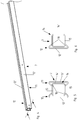
- the transverse bar 7 is composed of a plurality of longitudinal profile rails 12, 13 and stiffening profile 14 extending along the transverse bar 7, as will be explained below.
- the crossbar 7 is formed as Champgesch collectorter, preferably rectangular-shaped hollow beam.
- the crossbar 7 initially consists of two front longitudinal profile rail halves 12 'of the front longitudinal profile rail 12 and two rear longitudinal profile rail halves 13' of the front longitudinal profile rail 13, in particular Figure 3 and 7 demonstrate.
- one or two adjoining one another as a square hollow tubes 14 'stiffening profile 14 are arranged to the interior of the composite of the front and rear longitudinal profile rails 12 and 13 outer shell of the crossbar.
- the longitudinal profile rails 12 and 13 are formed with immediately adjacent to the stiffening profile 14 integrally formed upper or lower connecting plates 15 as Abkantprofil in its outer region 16, extending over 1 ⁇ 4 of the length of the crossbar 7, while in the middle 17 of the crossbar 7 about extending over the half of the length of the crossbar 7 in each case the upper and lower surfaces 18 of the reinforcing profiles forming Quadrathohlrohre 14 close the profile of the crossbar 7 on the top and bottom of the crossbar 7.
- the longitudinal profile rail halves are welded together with the Quadrathohlrohren to the crossbar 7 as a supporting element.
- the ends of the square tubes 14 and the longitudinal profile rail halves 12 ', 13' in the center 17 of the crossbar 7 are arranged overlapping each other, so as to obtain a better rigidity for the crossbar 7zu.
- the rails 12 and 13 are formed as Abkantprofil and have outside of the square tube 14 'formed stiffening profiles 14 directly to the stiffening profiles 14 then formed upper or lower connecting plates 15, which correspond to the adjacent parts of the joined to the crossbar 7 sections with each other are welded.
- the located in the middle length in the interior of the formed as a hollow bar 7 crossbar and connected to the longitudinal profile rails 12, 13 by welding as square tubes 14 'formed stiffening profiles 14 serve to increase the bending stiffness of the crossbar 7 in its central region, which extends approximately over the Half the length of the crossbar 7 extends its longitudinal extent.
- stiffening profiles 14 of the crossbar 7 determine the course and / or characteristics of the flexural rigidity of the crossbar 7.
- the bending stiffness of center 17 of the crossbar 7 is roughly graduated via its respective half to the respective outer end corresponding to the tools 8, 10 arranged on the crossbar 7.
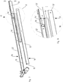
- the embodiment of the embodiment of the crossbar 18 according to the Fig. 9 to 15 differs from the embodiment of the crossbar 7 after the 2 to 8 by a different arrangement and design of the stiffening elements in the interior of the crossbar 7 by the use of stiffening rails 19 instead of stiffening profiles 14th
- stiffening profiles are formed on the rails 20 directly as stiffening rails 19 then formed.
- Fig. 9 to 15 is given an embodiment of the stiffening rails 19 of the crossbar 18, in which the flexural rigidity decreases from the middle of the crossbar 18 via its respective half to the respective outer end.
- the bending stiffness of the crossbar 18 decreases from the center of the crossbar 18 via its respective half to the respective outer end corresponding to the arranged on the crossbar 18 tools 8, 10 from.
Landscapes
- Life Sciences & Earth Sciences (AREA)
- Zoology (AREA)
- Engineering & Computer Science (AREA)
- Mechanical Engineering (AREA)
- Soil Sciences (AREA)
- Environmental Sciences (AREA)
- Body Structure For Vehicles (AREA)
Applications Claiming Priority (1)
| Application Number | Priority Date | Filing Date | Title |
|---|---|---|---|
| DE102016105650.2A DE102016105650A1 (de) | 2016-03-29 | 2016-03-29 | Querbalken zum Befestigen und Tragen von Werkzeugen eines landwirtschaftlichen Gerätes |
Publications (1)
| Publication Number | Publication Date |
|---|---|
| EP3228164A1 true EP3228164A1 (fr) | 2017-10-11 |
Family
ID=58501432
Family Applications (1)
| Application Number | Title | Priority Date | Filing Date |
|---|---|---|---|
| EP17401024.9A Withdrawn EP3228164A1 (fr) | 2016-03-29 | 2017-03-15 | Traverse destinée à fixer et supporter des outils d'un appareil agricole |
Country Status (2)
| Country | Link |
|---|---|
| EP (1) | EP3228164A1 (fr) |
| DE (1) | DE102016105650A1 (fr) |
Cited By (1)
| Publication number | Priority date | Publication date | Assignee | Title |
|---|---|---|---|---|
| EP3335533A1 (fr) * | 2016-12-13 | 2018-06-20 | Amazonen-Werke H. Dreyer GmbH & Co. KG | Semoir monograine à plusieurs rangées à cadre télescopique |
Citations (3)
| Publication number | Priority date | Publication date | Assignee | Title |
|---|---|---|---|---|
| EP2005811A2 (fr) | 2007-06-20 | 2008-12-24 | Amazonen-Werke H. Dreyer GmbH & Co. KG | Machine à semer |
| DE202009011632U1 (de) * | 2009-08-28 | 2010-02-25 | Rabe Agri Gmbh | Rahmengestell |
| DE102009044417A1 (de) * | 2009-11-04 | 2011-05-05 | Thyssenkrupp Steel Europe Ag | Profil und Verfahren zu dessen Herstellung |
-
2016
- 2016-03-29 DE DE102016105650.2A patent/DE102016105650A1/de active Pending
-
2017
- 2017-03-15 EP EP17401024.9A patent/EP3228164A1/fr not_active Withdrawn
Patent Citations (3)
| Publication number | Priority date | Publication date | Assignee | Title |
|---|---|---|---|---|
| EP2005811A2 (fr) | 2007-06-20 | 2008-12-24 | Amazonen-Werke H. Dreyer GmbH & Co. KG | Machine à semer |
| DE202009011632U1 (de) * | 2009-08-28 | 2010-02-25 | Rabe Agri Gmbh | Rahmengestell |
| DE102009044417A1 (de) * | 2009-11-04 | 2011-05-05 | Thyssenkrupp Steel Europe Ag | Profil und Verfahren zu dessen Herstellung |
Cited By (1)
| Publication number | Priority date | Publication date | Assignee | Title |
|---|---|---|---|---|
| EP3335533A1 (fr) * | 2016-12-13 | 2018-06-20 | Amazonen-Werke H. Dreyer GmbH & Co. KG | Semoir monograine à plusieurs rangées à cadre télescopique |
Also Published As
| Publication number | Publication date |
|---|---|
| DE102016105650A1 (de) | 2017-10-05 |
Similar Documents
| Publication | Publication Date | Title |
|---|---|---|
| WO2009100992A1 (fr) | Traverse de train de roulement pour un véhicule sur rails | |
| EP0303796B1 (fr) | Réservoir à l'épreuve de la pression | |
| DE102008019593A1 (de) | Hilfsrahmen im Fahrwerksbereich eines zweispurigen Fahrzeugs | |
| DE102008063448B4 (de) | Fahrzeugaufbau | |
| DE102008039807A1 (de) | Anhängekupplung | |
| DE102016105650A1 (de) | Querbalken zum Befestigen und Tragen von Werkzeugen eines landwirtschaftlichen Gerätes | |
| EP3009041B1 (fr) | Composant mural, tiroir dote d'un tel composant mural et meuble | |
| EP0800936A1 (fr) | Dispositif de fixation pour un attelage de remorque | |
| DE102009026297A1 (de) | Cockpitquerträger mit variablem Lenksäulenneigungswinkel | |
| DE102008009292A1 (de) | Versteifungsstruktur für ein rohrförmiges Bauteil | |
| EP1930490A2 (fr) | Traverse pour lame de métier à tisser | |
| EP3406509B1 (fr) | Cadre de vélo | |
| DE3934121A1 (de) | Gekroepfte zuggabel fuer mehrachsige, drehschemelgelenkte anhaengerfahrzeuge | |
| DE202009011632U1 (de) | Rahmengestell | |
| DE2812485C2 (fr) | ||
| DE102012107897A1 (de) | Selbstfahrende landwirtschaftliche Arbeitsmaschine | |
| EP3705386B1 (fr) | Cadre auxiliaire | |
| DE102005032412B4 (de) | Strukturträger als Karosseriebauteil | |
| DE7332914U (de) | Zwei wahlweise zu benutzende Zug ösen aufweisende Zuggabel fur Anhanger fahrzeuge | |
| EP2861051B1 (fr) | Accessoire de moisson pour une moissonneuse | |
| DE3031018C2 (fr) | ||
| EP4088705A1 (fr) | Cadre pliant pour un fauteuil roulant | |
| DE19935778A1 (de) | Deichselanordnung | |
| DE102022119905A1 (de) | Anhängekupplung | |
| DE202015006216U1 (de) | Verbindungsanordnung, damit ausgerüstetes Gestell, insbesondere Ladungsträger für Turmsegmente oder Rotorblätter von Windenergieanlagen, und Bausatz für das Gestell |
Legal Events
| Date | Code | Title | Description |
|---|---|---|---|
| PUAI | Public reference made under article 153(3) epc to a published international application that has entered the european phase |
Free format text: ORIGINAL CODE: 0009012 |
|
| AK | Designated contracting states |
Kind code of ref document: A1 Designated state(s): AL AT BE BG CH CY CZ DE DK EE ES FI FR GB GR HR HU IE IS IT LI LT LU LV MC MK MT NL NO PL PT RO RS SE SI SK SM TR |
|
| AX | Request for extension of the european patent |
Extension state: BA ME |
|
| 17P | Request for examination filed |
Effective date: 20180215 |
|
| RBV | Designated contracting states (corrected) |
Designated state(s): AL AT BE BG CH CY CZ DE DK EE ES FI FR GB GR HR HU IE IS IT LI LT LU LV MC MK MT NL NO PL PT RO RS SE SI SK SM TR |
|
| 17Q | First examination report despatched |
Effective date: 20200207 |
|
| STAA | Information on the status of an ep patent application or granted ep patent |
Free format text: STATUS: THE APPLICATION HAS BEEN WITHDRAWN |
|
| 18W | Application withdrawn |
Effective date: 20201123 |