EP3228342B1 - Tropfkammer mit hydrophober innenfläche - Google Patents
Tropfkammer mit hydrophober innenfläche Download PDFInfo
- Publication number
- EP3228342B1 EP3228342B1 EP17162653.4A EP17162653A EP3228342B1 EP 3228342 B1 EP3228342 B1 EP 3228342B1 EP 17162653 A EP17162653 A EP 17162653A EP 3228342 B1 EP3228342 B1 EP 3228342B1
- Authority
- EP
- European Patent Office
- Prior art keywords
- interior surface
- hydrophobic portion
- light
- portions
- drip chamber
- Prior art date
- Legal status (The legal status is an assumption and is not a legal conclusion. Google has not performed a legal analysis and makes no representation as to the accuracy of the status listed.)
- Not-in-force
Links
- 230000002209 hydrophobic effect Effects 0.000 title claims description 74
- 239000007788 liquid Substances 0.000 claims description 22
- 238000001802 infusion Methods 0.000 claims description 13
- 230000005499 meniscus Effects 0.000 claims description 11
- 238000012634 optical imaging Methods 0.000 claims description 11
- 238000000034 method Methods 0.000 claims description 7
- 238000003384 imaging method Methods 0.000 claims description 4
- 238000013507 mapping Methods 0.000 claims description 4
- 239000011248 coating agent Substances 0.000 claims description 3
- 238000000576 coating method Methods 0.000 claims description 3
- 238000012544 monitoring process Methods 0.000 claims description 3
- 238000004519 manufacturing process Methods 0.000 claims description 2
- 230000001846 repelling effect Effects 0.000 claims description 2
- 239000000463 material Substances 0.000 description 11
- 230000005540 biological transmission Effects 0.000 description 5
- 239000012530 fluid Substances 0.000 description 5
- 230000000737 periodic effect Effects 0.000 description 4
- 239000000243 solution Substances 0.000 description 4
- 239000000126 substance Substances 0.000 description 4
- 230000005661 hydrophobic surface Effects 0.000 description 3
- 238000012986 modification Methods 0.000 description 3
- 230000004048 modification Effects 0.000 description 3
- 230000003287 optical effect Effects 0.000 description 3
- 238000000748 compression moulding Methods 0.000 description 2
- 229920000642 polymer Polymers 0.000 description 2
- XLYOFNOQVPJJNP-UHFFFAOYSA-N water Substances O XLYOFNOQVPJJNP-UHFFFAOYSA-N 0.000 description 2
- 239000004793 Polystyrene Substances 0.000 description 1
- NIXOWILDQLNWCW-UHFFFAOYSA-N acrylic acid group Chemical group C(C=C)(=O)O NIXOWILDQLNWCW-UHFFFAOYSA-N 0.000 description 1
- 230000001154 acute effect Effects 0.000 description 1
- 150000001298 alcohols Chemical class 0.000 description 1
- 238000009833 condensation Methods 0.000 description 1
- 230000005494 condensation Effects 0.000 description 1
- 230000004069 differentiation Effects 0.000 description 1
- 238000004049 embossing Methods 0.000 description 1
- 238000005516 engineering process Methods 0.000 description 1
- 230000008020 evaporation Effects 0.000 description 1
- 238000001704 evaporation Methods 0.000 description 1
- 230000006870 function Effects 0.000 description 1
- 230000004313 glare Effects 0.000 description 1
- 239000011521 glass Substances 0.000 description 1
- 238000001746 injection moulding Methods 0.000 description 1
- 238000001990 intravenous administration Methods 0.000 description 1
- 238000005259 measurement Methods 0.000 description 1
- 239000000203 mixture Substances 0.000 description 1
- 239000003921 oil Substances 0.000 description 1
- 239000004417 polycarbonate Substances 0.000 description 1
- 229920000515 polycarbonate Polymers 0.000 description 1
- 229920002223 polystyrene Polymers 0.000 description 1
- -1 polytetrafluoroethylene Polymers 0.000 description 1
- 229920001343 polytetrafluoroethylene Polymers 0.000 description 1
- 239000004810 polytetrafluoroethylene Substances 0.000 description 1
- 239000000843 powder Substances 0.000 description 1
- 102000004169 proteins and genes Human genes 0.000 description 1
- 108090000623 proteins and genes Proteins 0.000 description 1
- 238000009877 rendering Methods 0.000 description 1
- 230000002940 repellent Effects 0.000 description 1
- 239000005871 repellent Substances 0.000 description 1
- 238000012360 testing method Methods 0.000 description 1
- 125000000391 vinyl group Chemical group [H]C([*])=C([H])[H] 0.000 description 1
- 229920002554 vinyl polymer Polymers 0.000 description 1
- 230000000007 visual effect Effects 0.000 description 1
- 239000001993 wax Substances 0.000 description 1
Images
Classifications
-
- A—HUMAN NECESSITIES
- A61—MEDICAL OR VETERINARY SCIENCE; HYGIENE
- A61M—DEVICES FOR INTRODUCING MEDIA INTO, OR ONTO, THE BODY; DEVICES FOR TRANSDUCING BODY MEDIA OR FOR TAKING MEDIA FROM THE BODY; DEVICES FOR PRODUCING OR ENDING SLEEP OR STUPOR
- A61M5/00—Devices for bringing media into the body in a subcutaneous, intra-vascular or intramuscular way; Accessories therefor, e.g. filling or cleaning devices, arm-rests
- A61M5/14—Infusion devices, e.g. infusing by gravity; Blood infusion; Accessories therefor
- A61M5/168—Means for controlling media flow to the body or for metering media to the body, e.g. drip meters, counters ; Monitoring media flow to the body
- A61M5/16886—Means for controlling media flow to the body or for metering media to the body, e.g. drip meters, counters ; Monitoring media flow to the body for measuring fluid flow rate, i.e. flowmeters
- A61M5/1689—Drip counters
-
- A—HUMAN NECESSITIES
- A61—MEDICAL OR VETERINARY SCIENCE; HYGIENE
- A61M—DEVICES FOR INTRODUCING MEDIA INTO, OR ONTO, THE BODY; DEVICES FOR TRANSDUCING BODY MEDIA OR FOR TAKING MEDIA FROM THE BODY; DEVICES FOR PRODUCING OR ENDING SLEEP OR STUPOR
- A61M5/00—Devices for bringing media into the body in a subcutaneous, intra-vascular or intramuscular way; Accessories therefor, e.g. filling or cleaning devices, arm-rests
- A61M5/14—Infusion devices, e.g. infusing by gravity; Blood infusion; Accessories therefor
- A61M5/1411—Drip chambers
-
- A—HUMAN NECESSITIES
- A61—MEDICAL OR VETERINARY SCIENCE; HYGIENE
- A61M—DEVICES FOR INTRODUCING MEDIA INTO, OR ONTO, THE BODY; DEVICES FOR TRANSDUCING BODY MEDIA OR FOR TAKING MEDIA FROM THE BODY; DEVICES FOR PRODUCING OR ENDING SLEEP OR STUPOR
- A61M2205/00—General characteristics of the apparatus
- A61M2205/33—Controlling, regulating or measuring
- A61M2205/3306—Optical measuring means
-
- A—HUMAN NECESSITIES
- A61—MEDICAL OR VETERINARY SCIENCE; HYGIENE
- A61M—DEVICES FOR INTRODUCING MEDIA INTO, OR ONTO, THE BODY; DEVICES FOR TRANSDUCING BODY MEDIA OR FOR TAKING MEDIA FROM THE BODY; DEVICES FOR PRODUCING OR ENDING SLEEP OR STUPOR
- A61M2207/00—Methods of manufacture, assembly or production
-
- Y—GENERAL TAGGING OF NEW TECHNOLOGICAL DEVELOPMENTS; GENERAL TAGGING OF CROSS-SECTIONAL TECHNOLOGIES SPANNING OVER SEVERAL SECTIONS OF THE IPC; TECHNICAL SUBJECTS COVERED BY FORMER USPC CROSS-REFERENCE ART COLLECTIONS [XRACs] AND DIGESTS
- Y10—TECHNICAL SUBJECTS COVERED BY FORMER USPC
- Y10T—TECHNICAL SUBJECTS COVERED BY FORMER US CLASSIFICATION
- Y10T29/00—Metal working
- Y10T29/49—Method of mechanical manufacture
- Y10T29/49826—Assembling or joining
Definitions
- the present disclosure relates to a drip chamber, for an infusion tube, with an interior surface having a hydrophobic surface, in particular, a hydrophobic surface with optical properties enabling optical imaging through the hydrophobic surface.
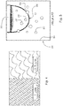
- FIG. 5 is a pictorial representation of prior art drip chamber 200 with spurious droplets 202 clinging to interior surface 204 of the drip chamber.
- Figure 5 is presented as a line drawing.
- droplets of fluid such as droplets 202
- Droplets 202 can cause substantial problems with respect to imaging the drip chamber, for example, imaging drop 206 pendant from drip tube 208.
- the droplets can cause errors in the measurement of the size of drop 206.
- Droplets such as droplets 202 in other portions of the drip tube, for example in the vicinity of a meniscus can cause similar problems, such as errors in measuring a position/level of the meniscus.
- WO 2012/104779 discloses a system comprising a drip chamber having an inlet and an outlet and an optical monitoring apparatus.
- US 4,490,140 discloses an intravenous monitoring system comprising a drip chamber having an inlet and an outlet and a light sensor for detecting the presence of liquid passing through the drip chamber.
- EP 1 693 077 A2 discloses a drip chamber having an inlet, an outlet and a pressure activated valve.
- a drip chamber for an infusion tube including: a first end including a drip tube; a second end including an exit port; and a wall connecting the first and second ends and including an interior surface with a hydrophobic portion.
- the drip chamber includes a space enclosed by the interior wall and the first and second ends.
- the hydrophobic portion of the interior surface repels liquid contacting the hydrophobic coating.
- the hydrophobic portion of the interior surface enables light to refract through the hydrophobic portion and the wall in the same manner as is the case when the hydrophobic portion is not present on the interior surface.
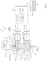
- Figure 1 is a schematic representation of optical imaging system 100 including drip chamber 102 with a hydrophobic portion of the interior surface.
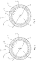
- Figure 2 is a cross-section of drip chamber 102 generally along line 2-2 in Figure 1 .
- FIG 3 is a cross-section of drip chamber 102 generally along line 3-3 in Figure 1 .
- Drip chamber 102 for infusion tube 104 includes end 106 with drip tube 108 and end 110 including exit port 112.
- Drip chamber 102 includes wall 114 connecting ends 106 and 110.
- Wall 114 includes interior surface 116 having at least one hydrophobic portion 118. It should be understood that Figures 2 and 3 are not scale drawings and that the thickness of portion 118 in Figures 2 and 3 is exaggerated for purposes of illustration.
- Wall 114 includes space 122 enclosed by interior surface 116 and ends 106 and 110. Hydrophobic portion 118 repels liquid 124 in drip chamber 102.
- Hydrophobic portion 118 is optically clear and enables light to refract through hydrophobic portion 118 and wall 114 in the same manner as is the case when the hydrophobic portion 118 is not present on interior surface 116, as further described below. Stated otherwise, hydrophobic portion 118 enables direct mapping of light 126A and 126B, passing through portion 118, from a point, such as pendant drop 128 on drip tube 108, within drip chamber 102, to a point on an image (described below) of the point in drip chamber 102. That is, hydrophobic portion 118 enables points illuminated in drip chamber 102 by the emitted light to be accurately imaged using light transmitted through hydrophobic portion 118.
- infusion tube 104 includes output tube 130.
- hydrophobic portion 118 is aligned with portion 132 of drip chamber 102, including end 106, in direction R orthogonal to longitudinal axis LA for drip chamber 102.
- Axis LA passes through ends 106 and 110.
- Portion 132 is sized to include drop 128 pendant from end 134 of drip tube 108.
- Optical imaging of drop(s) 128 can be used to control flow of liquid 124 through drip chamber 102 or can be used to detect alarm conditions, such as an empty bag alarm for bag 136 supplying liquid 124 to drip chamber 102.
- hydrophobic portion 118 is aligned with portion 138 of drip chamber 102, between ends 106 and 110, in direction R.
- portion 138 is located to include meniscus 140 for liquid 124 in drip chamber 102.
- hydrophobic portion 118 enables accurate optical imaging of meniscus 140 by preventing the droplets described above from forming on portion 118, while enabling undistorted light transmission.
- Optical imaging of meniscus 140 can be used to determine a level of liquid 124 in chamber 102, which can be used to control flow of liquid 124 through drip chamber 102.
- hydrophobic portion 118 covers both portions 132 and 138.
- hydrophobic portion 118 covers more than portions 132 and 138.
- hydrophobic portion 118 covers the entirety of surface 116 between ends 106 or 110.
- a contact angle for liquid 124 in contact with hydrophobic portion 118 is between 90 and 180 degrees.
- the contact angle is an angle, measured through liquid, such as liquid 124, where a liquid interface contacts a hydrophobic material, such as hydrophobic portion 118. The angle range described above enables robust repelling of liquid from portion 118.
- Figure 4 is a picture illustrating example periodic structure for hydrophobic portion 118.
- hydrophobic portion 118 includes a plurality of periodic structures.
- hydrophobic portion 118 includes a plurality of structures in a non-periodic configuration.
- hydrophobic portion 118 is formed of a same piece of material forming wall 114, that is, hydrophobic portion 118 is integral to material forming wall 114.
- interior surface 116 is operated upon in some fashion to create hydrophobic portion 118.
- interior surface 116 can be molded using injection molding, injection-compression molding, compression molding, or embossing, to form hydrophobic portion 118.
- Hydrophobic portion 118 can be formed by modifying surface 116 with surface modification technologies such as plasma.
- hydrophobic portion 118 is formed of a material 141, separate from material 143 forming wall 114.
- Material 141 is adhered to material 143.
- Material 141 can include a polymer, such as, but not limited to acrylic, polystyrene, polycarbonate, vinyl or a mixture of polymers.
- hydrophobic portion 118 is a coating free of microstructure, such as wax, polytetrafluoroethylene, or water repellent glass powder, applied to surface 116.
- the material forming hydrophobic portion 118 is fluorinated to improve hydrophobic properties.
- hydrophobic portion 118 reflects less than one percent of light incident upon hydrophobic portion 118.
- the vast majority of light incident upon hydrophobic portion 118 is transmitted through wall 114, enabling high resolution and accurate imagery, and virtually eliminating fresnel reflectance or glare.
- hydrophobic portion 118 repels: inorganic liquid such as water; organic liquid such as alcohols, proteins, and oils; a solution of an inorganic liquid with a dissolved organic substance; a solution of an inorganic liquid with a dissolved inorganic substance; a solution of an organic liquid with a dissolved organic substance; and, a solution of an organic liquid with a dissolved inorganic substance.
- Hydrophobic portion 118 can be a one-dimensional or a two-dimensional array of microstructure. Hydrophobic portion 118 can have random or stochastic structure. The depth of hydrophobic portion 118 can be between 50nm and 500nm. The pitch of an array of hydrophobic microstructure for hydrophobic portion 118 can be between 50nam and 500nm.
- the microstructure when hydrophobic portion 118 is microstructured, can have a cross-sectional profile that is substantially triangular, partially elliptical, parabolic, or hair-like with an indeterminate profile.
- surface 116 is transparent to light 126A and 126B, but is tinted for visual differentiation by the naked eye.
- the microstructure is oriented substantially orthogonal to wall 114. In an example, the microstructure is oriented at an acute angle with respect to wall 114, for example, angled toward end 106 or toward end 110.
- optical imaging system 100 can be used with infusion tube 104 including drip chamber 102.
- system 100 includes at least one light source 142, for example sources 142A and 142B for emitting light 126A and 126B, respectively, and system 100 includes optics system 144.
- System 144 includes at least one lens 148, for example, lenses 148A and 148B, and at least one image sensor 150, for example, sensors 150A and 150B.
- Lenses 148A and 148B are for receiving and transmitting light 126A and 126B transmitted through hydrophobic portion 118 of the interior surface and portions 132 and 138, respectively.
- Sensors 150A and 150B receive the transmitted light 126A and 126B from lenses 148A and 148B, respectively, and generate and transmit data 152A and 152B characterizing transmitted light 126A and 126B from lenses 148A and 148B, respectively.
- System 100 includes at least one specially programmed processor 156 configured to generate images 158A and 158B of portions 132 and 138, respectively.
- System 100 includes memory element 160 configured to store computer executable instructions 162.
- Processor 156 is configured to execute instructions 162 to generate images 158A and 158B.
- system can include only light source 142A, lens 148A, and sensor 150A, and not light source 142B, lens 148B, and sensor 150B, or light source 142B, lens 148B, and sensor 150B and not light source 142A, lens 148A, and sensor 150A.
- image 158A can include pendant drop 128 and image 158A can be used to control flow through infusion tube 102 or to monitor for alarm conditions.
- image 158B can include meniscus 140 and image 158B can be used to monitor the level of meniscus 140 in drip chamber 102.
- hydrophobic portion 118 enables more accurate and precise images 158A and 158B by eliminating spurious droplets, noted above, clinging to interior surface 116, while enabling undistorted or diffused light transmission.
- a rendering of pendant drop 128 in image 158A is not cluttered or obscured by spurious droplets clinging to surface 116 in portion 130, while at the same time benefiting from diffused transmission of the light used to form image 158A.
- the boundary of meniscus 140 is not obscured or distorted by spurious droplets clinging to surface 116 in portion 138 between meniscus 140 and portion 130, while at the same time benefiting from diffused transmission of the light used to form image 158B.
Landscapes
- Health & Medical Sciences (AREA)
- Vascular Medicine (AREA)
- Engineering & Computer Science (AREA)
- Anesthesiology (AREA)
- Biomedical Technology (AREA)
- Heart & Thoracic Surgery (AREA)
- Hematology (AREA)
- Life Sciences & Earth Sciences (AREA)
- Animal Behavior & Ethology (AREA)
- General Health & Medical Sciences (AREA)
- Public Health (AREA)
- Veterinary Medicine (AREA)
- Physics & Mathematics (AREA)
- Fluid Mechanics (AREA)
- Infusion, Injection, And Reservoir Apparatuses (AREA)
Claims (7)
- Verfahren zum Herstellen einer Tropfkammer für einen Infusionsschlauch, Folgendes umfassend:Ausbilden eines ersten Endes (106) einschließlich eines Tropfschlauchs (108);Ausbilden eines zweiten Endes (110) einschließlich einer Austrittsöffnung (112);Ausbilden einer Wand (114), die das erste und das zweite Ende verbindet und dadurch gekennzeichnet ist, dass sie eine innere Oberfläche (116) mit einem hydrophoben Abschnitt (118) einschließt; undUmschließen eines Raums (122) mit der inneren Oberfläche und dem ersten und dem zweiten Ende,wobei:der hydrophobe Abschnitt der inneren Oberfläche Flüssigkeit abweist, die die hydrophobe Beschichtung berührt, undder hydrophobe Abschnitt der inneren Oberfläche zulässt, dass Licht durch den hydrophoben Abschnitt und die Wand auf die gleiche Weise gebrochen wird, wie es der Fall ist, wenn der hydrophobe Abschnitt an der inneren Oberfläche nicht vorliegt.
- Verfahren nach Anspruch 1, wobei der hydrophobe Abschnitt (118) der inneren Oberfläche (116) ein direktes Abzeichnen des Lichts zulässt, das durch den hydrophoben Abschnitt der inneren Oberfläche tritt, von einem Punkt innerhalb der Tropfkammer zu einem Punkt auf einer Abbildung des Punktes in der Tropfkammer.
- Verfahren nach Anspruch 1, wobei der hydrophobe Abschnitt (118) der inneren Oberfläche (116) an dem Ende des Tropfschlauchs (108) in einer Richtung ausgerichtet ist, die senkrecht zu einer Längsachse für die Tropfkammer, die durch das erste und das zweite Ende (106, 110) der Tropfkammer verläuft, steht.
- Optisches bildgebendes System für einen Infusionsschlauch, Folgendes umfassend:eine Tropfkammer (102), einschließlich:eines ersten Abschnitts mit einem Tropfschlauch (108);eines zweiten Abschnitts mit einer Austrittsöffnung (112);eines dritten Abschnitts, der zwischen dem ersten und dem zweiten Abschnitt liegt; undeiner Wand (114):die das erste und das zweite Ende verbindet; unddadurch gekennzeichnet, dass sie eine innere Oberfläche (116) mit einem hydrophoben Abschnitt (118) einschließt, die an dem ersten und/oder dem dritten Abschnitt in einer Richtung ausgerichtet ist, die senkrecht zu einer Längsachse für die Tropfkammer, die durch den ersten und den zweiten Abschnitt verläuft, steht;wenigstens einer Lichtquelle (126) zum Emittieren von Licht;eines optischen Systems, einschließlich:wenigstens einer Linse (148) zum Empfangen und Übertragen des Lichts, das durch den hydrophoben Abschnitt der inneren Oberfläche und den ersten und/oder den dritten Abschnitt übertragen wird; undeines Bildsensors (150) zum:Empfangen des übertragenen Lichts von der wenigstens einen Linse; und,Erzeugen und Übertragen von Daten, die das übertragene Licht von der wenigstens einen Linse charakterisieren;eines Speicherelements (160), konfiguriert zum Speichern von computerlesbaren Anweisungen; undwenigstens eines speziell programmierten Prozessors (156), konfiguriert zum Ausführen der computerlesbaren Anweisungen, um, unter Verwendung der Daten, wenigstens eine Abbildung des ersten Abschnitts, einschließlich einer Abbildung eines herabhängenden Tropfens zum Steuern des Strömens durch einen Infusionsschlauch, und/oder des dritten Abschnitts, einschließlich einer Abbildung eines Meniskus zum Überwachen des Niveaus des Meniskus in der Tropfkammer, zu erzeugen,wobei:der hydrophobe Abschnitt der inneren Oberfläche Flüssigkeit abweist, die den hydrophoben Abschnitt der inneren Oberfläche berührt, undder hydrophobe Abschnitt der inneren Oberfläche zulässt, dass das Licht durch den hydrophoben Abschnitt der inneren Oberfläche tritt, ohne gestreut zu werden.
- Optisches bildgebendes System nach Anspruch 4, wobei der hydrophobe Abschnitt (118) der inneren Oberfläche (116) ein direktes Abzeichnen des Lichts von entsprechenden Punkten innerhalb des ersten oder des dritten Abschnitts zu entsprechenden Punkten auf der wenigstens einen Abbildung zulässt.
- Verfahren zum Abzeichnen eines Infusionsschlauchs mit einer Tropfkammer einschließlich eines ersten Abschnitts mit einem Tropfschlauch (108), eines zweiten Abschnitts mit einer Austrittsöffnung (112), eines zwischen dem ersten und dem zweiten Abschnitt gelegenen dritten Abschnitts, und einer Wand (114), die den ersten und den zweiten Abschnitt verbindet und eine innere Oberfläche (116) mit einem hydrophoben Abschnitt (118) einschließt, der an dem ersten und/oder dem dritten Abschnitt in einer Richtung ausgerichtet ist, die senkrecht zu einer Längsachse für die Tropfkammer, die durch den ersten und den zweiten Abschnitt verläuft, steht, gekennzeichnet durch:Abweisen von Flüssigkeit, die den hydrophoben Abschnitt der inneren Oberfläche berührt;Emittieren von Licht, unter Verwendung wenigstens von wenigstens einer Lichtquelle (126);Übertragen des Lichts durch den hydrophoben Abschnitt der inneren Oberfläche und den ersten und/oder den dritten Abschnitt, ohne das Licht zu streuen;Empfangen des durch den hydrophoben Abschnitt der inneren Oberfläche und den ersten und/oder den dritten Abschnitt übertragenen Lichts, unter Verwendung wenigstens einer Linse (148);Übertragen des durch den hydrophoben Abschnitt der inneren Oberfläche und den ersten und/oder den dritten Abschnitt übertragenen Lichts von der wenigstens einen Linse;Empfangen des übertragenen Lichts von der wenigstens einen Linse, unter Verwendung eines Bildsensors (150);Erzeugen und Übertragen von Daten, die das übertragene Licht von der wenigstens einen Linse charakterisieren, unter Verwendung des Bildsensors;Speichern von computerlesbaren Anweisungen in einem Speicherelement (160); und,Ausführen der computerlesbaren Anweisungen, unter Verwendung wenigstens eines speziell programmierten Prozessors (156) und der Daten, um wenigstens eine Abbildung des ersten und/oder des dritten Abschnitts zu erzeugen.
- Verfahren nach Anspruch 6, ferner umfassend: direktes Abzeichnen des Lichts von entsprechenden Punkten innerhalb des ersten und/oder des dritten Abschnitts zu entsprechenden Punkten auf der wenigstens einen Abbildung, unter Verwendung des wenigstens einen speziell programmierten Prozessors (156).
Applications Claiming Priority (3)
| Application Number | Priority Date | Filing Date | Title |
|---|---|---|---|
| US13/828,859 US9352081B2 (en) | 2013-03-14 | 2013-03-14 | Drip chamber with hydrophobic interior surface |
| EP14715788.7A EP2968734B1 (de) | 2013-03-14 | 2014-03-13 | Tropfkammer mit hydrophober innenfläche |
| PCT/US2014/026156 WO2014160249A1 (en) | 2013-03-14 | 2014-03-13 | Drip chamber with hydrophobic interior surface |
Related Parent Applications (2)
| Application Number | Title | Priority Date | Filing Date |
|---|---|---|---|
| EP14715788.7A Division-Into EP2968734B1 (de) | 2013-03-14 | 2014-03-13 | Tropfkammer mit hydrophober innenfläche |
| EP14715788.7A Division EP2968734B1 (de) | 2013-03-14 | 2014-03-13 | Tropfkammer mit hydrophober innenfläche |
Publications (2)
| Publication Number | Publication Date |
|---|---|
| EP3228342A1 EP3228342A1 (de) | 2017-10-11 |
| EP3228342B1 true EP3228342B1 (de) | 2018-12-26 |
Family
ID=50440865
Family Applications (2)
| Application Number | Title | Priority Date | Filing Date |
|---|---|---|---|
| EP14715788.7A Not-in-force EP2968734B1 (de) | 2013-03-14 | 2014-03-13 | Tropfkammer mit hydrophober innenfläche |
| EP17162653.4A Not-in-force EP3228342B1 (de) | 2013-03-14 | 2014-03-13 | Tropfkammer mit hydrophober innenfläche |
Family Applications Before (1)
| Application Number | Title | Priority Date | Filing Date |
|---|---|---|---|
| EP14715788.7A Not-in-force EP2968734B1 (de) | 2013-03-14 | 2014-03-13 | Tropfkammer mit hydrophober innenfläche |
Country Status (14)
| Country | Link |
|---|---|
| US (4) | US9352081B2 (de) |
| EP (2) | EP2968734B1 (de) |
| JP (1) | JP6400668B2 (de) |
| KR (1) | KR102181773B1 (de) |
| AR (1) | AR097804A1 (de) |
| AU (1) | AU2014243979B2 (de) |
| BR (1) | BR112015022752A2 (de) |
| CA (1) | CA2905971C (de) |
| CL (1) | CL2015002568A1 (de) |
| ES (2) | ES2716755T3 (de) |
| MX (1) | MX364001B (de) |
| SG (1) | SG11201507330YA (de) |
| WO (1) | WO2014160249A1 (de) |
| ZA (1) | ZA201507046B (de) |
Families Citing this family (23)
| Publication number | Priority date | Publication date | Assignee | Title |
|---|---|---|---|---|
| US9151646B2 (en) | 2011-12-21 | 2015-10-06 | Deka Products Limited Partnership | System, method, and apparatus for monitoring, regulating, or controlling fluid flow |
| US9435455B2 (en) | 2011-12-21 | 2016-09-06 | Deka Products Limited Partnership | System, method, and apparatus for monitoring, regulating, or controlling fluid flow |
| US9746093B2 (en) | 2011-12-21 | 2017-08-29 | Deka Products Limited Partnership | Flow meter and related system and apparatus |
| US10228683B2 (en) | 2011-12-21 | 2019-03-12 | Deka Products Limited Partnership | System, method, and apparatus for monitoring, regulating, or controlling fluid flow |
| US10488848B2 (en) | 2011-12-21 | 2019-11-26 | Deka Products Limited Partnership | System, method, and apparatus for monitoring, regulating, or controlling fluid flow |
| US9372486B2 (en) | 2011-12-21 | 2016-06-21 | Deka Products Limited Partnership | System, method, and apparatus for monitoring, regulating, or controlling fluid flow |
| US9746094B2 (en) | 2011-12-21 | 2017-08-29 | Deka Products Limited Partnership | Flow meter having a background pattern with first and second portions |
| US9724466B2 (en) | 2011-12-21 | 2017-08-08 | Deka Products Limited Partnership | Flow meter |
| US9759343B2 (en) | 2012-12-21 | 2017-09-12 | Deka Products Limited Partnership | Flow meter using a dynamic background image |
| US9234850B2 (en) | 2013-03-14 | 2016-01-12 | Baxter International Inc. | Drip chamber with integrated optics |
| US9352081B2 (en) * | 2013-03-14 | 2016-05-31 | Baxter International Inc. | Drip chamber with hydrophobic interior surface |
| USD745661S1 (en) | 2013-11-06 | 2015-12-15 | Deka Products Limited Partnership | Apparatus to control fluid flow through a tube |
| USD752209S1 (en) | 2013-11-06 | 2016-03-22 | Deka Products Limited Partnership | Apparatus to control fluid flow through a tube |
| USD749206S1 (en) | 2013-11-06 | 2016-02-09 | Deka Products Limited Partnership | Apparatus to control fluid flow through a tube |
| USD751689S1 (en) | 2013-11-06 | 2016-03-15 | Deka Products Limited Partnership | Apparatus to control fluid flow through a tube |
| USD751690S1 (en) | 2013-11-06 | 2016-03-15 | Deka Products Limited Partnership | Apparatus to control fluid flow through a tube |
| WO2017043623A1 (ja) * | 2015-09-09 | 2017-03-16 | 株式会社村田製作所 | 滴下検出装置 |
| JP6172422B1 (ja) * | 2015-10-23 | 2017-08-02 | 株式会社村田製作所 | 点滴筒および輸液セット |
| USD905848S1 (en) | 2016-01-28 | 2020-12-22 | Deka Products Limited Partnership | Apparatus to control fluid flow through a tube |
| EP4335471A3 (de) | 2016-01-28 | 2024-08-21 | DEKA Products Limited Partnership | Vorrichtung zur überwachung, regelung oder steuerung eines fluidstroms |
| USD854145S1 (en) | 2016-05-25 | 2019-07-16 | Deka Products Limited Partnership | Apparatus to control fluid flow through a tube |
| USD964563S1 (en) | 2019-07-26 | 2022-09-20 | Deka Products Limited Partnership | Medical flow clamp |
| WO2021021596A1 (en) | 2019-07-26 | 2021-02-04 | Deka Products Limited Partnership | Apparatus for monitoring, regulating, or controlling fluid flow |
Family Cites Families (51)
| Publication number | Priority date | Publication date | Assignee | Title |
|---|---|---|---|---|
| IL62337A (en) * | 1980-04-16 | 1984-07-31 | Leibinsohn Saul | Liquid flow measuring device particularly useful as a drip chamber for infusion sets |
| US4321461A (en) | 1980-04-18 | 1982-03-23 | K/W/D Associates | Flow rate monitor and totalizer with count display |
| US4328801A (en) | 1980-10-30 | 1982-05-11 | Alvin J. Marx | Automated intravenous fluid regulating and administering apparatus |
| US4490140A (en) | 1982-07-30 | 1984-12-25 | Abbott Laboratories | Intravenous monitoring system utilizing a dynamic reference threshold |
| US4525163A (en) | 1982-08-06 | 1985-06-25 | Nuvatec, Inc. | Intravenous set flow control device |
| US4504263A (en) * | 1982-12-22 | 1985-03-12 | Valleylab, Inc. | Flow rate monitor with optical sensing chamber |
| JPS59189862A (ja) * | 1983-04-06 | 1984-10-27 | サウル・レイビンソ−ン | 特に点滴室用に有用なる液流測定装置 |
| US4583975A (en) | 1983-12-23 | 1986-04-22 | Baxter Travenol Laboratories, Inc. | Indirect piezoelectric drop counter and method |
| US4634426A (en) | 1984-12-11 | 1987-01-06 | Baxter Travenol Laboratories | Medical infusion controller and user interface |
| US4820281A (en) | 1987-05-21 | 1989-04-11 | Ivy Medical, Inc. | Drop volume measurement system |
| US4936828A (en) | 1987-06-02 | 1990-06-26 | Kophu Chiang | Liquid drop image sensor |
| NL8802307A (nl) | 1987-12-17 | 1989-07-17 | Mr W M H Kerbosch B V Handelen | Inrichting voor het regelen van de stroomsnelheid van een infusievloeistof bij een infusiesysteem. |
| US5045069A (en) | 1989-01-17 | 1991-09-03 | Robert Imparato | Portable infusion monitor |
| US5057090A (en) | 1990-06-07 | 1991-10-15 | Bessman Edward S | Drip metering apparatus with selectable drop sizes and coupling arrangement therein |
| US5415641A (en) | 1991-04-01 | 1995-05-16 | Sherwood Medical Company | Drop detection method and apparatus |
| US5186057A (en) * | 1991-10-21 | 1993-02-16 | Everhart Howard R | Multi-beam liquid-drop size/rate detector apparatus |
| US6049381A (en) | 1993-10-29 | 2000-04-11 | The United States Of America As Represented By The Secretary Of The Navy | Real time suspended particle monitor |
| US5562615A (en) | 1994-02-28 | 1996-10-08 | Corpak, Inc. | Free flow detector for an enternal feeding pump |
| LU88565A1 (fr) | 1994-12-07 | 1996-07-15 | Midex Marketing Ltd | Dispositif pour la surveillance du débit d'une perfusion intraveineuse |
| KR100376646B1 (ko) | 1996-07-01 | 2003-03-15 | 파마시아 에이비 | 전달 장치 및 이것의 작동 방법 |
| US5899665A (en) | 1997-06-11 | 1999-05-04 | Alaris Medical Systems, Inc. | Method and apparatus for controlling infusion volume |
| GB9803299D0 (en) | 1998-02-18 | 1998-04-08 | Gallagher George | Improved method and apparatus for monitoring intravenous drips |
| US6159186A (en) | 1998-03-13 | 2000-12-12 | Wft Projects (Proprietary) Limited | Infusion delivery system |
| US20030006159A1 (en) * | 1999-09-01 | 2003-01-09 | Jorgen Thorball | Additive tube for enteral nutrition apparatus |
| US6149631A (en) | 1999-09-10 | 2000-11-21 | Haydel, Jr.; Leo Joseph | Drip impinging intravenous drip chamber |
| US6413238B1 (en) | 1999-09-17 | 2002-07-02 | Baxter International Inc | Fluid dispenser with stabilized fluid flow |
| IL133495A (en) | 1999-12-13 | 2006-12-31 | Menahem Kraus | Membrane support for drip chamber |
| US7479128B1 (en) * | 2000-01-04 | 2009-01-20 | Boston Scientific Scimed, Inc. | Protective coatings for medical devices |
| US6562012B1 (en) | 2000-11-20 | 2003-05-13 | Alaris Medical Systems, Inc. | Apparatus and method for measuring drop size in an intravenous drip chamber |
| US6599282B2 (en) | 2001-09-05 | 2003-07-29 | Zeev Burko | Intravenous set flow volumetric measurement device |
| US6984052B1 (en) | 2002-10-11 | 2006-01-10 | Gil Del Castillo | Drip chamber illumination device |
| US7190275B2 (en) | 2002-11-14 | 2007-03-13 | Goldberg Barry A | Drip rate monitor for intravenous infusion set |
| US6877877B2 (en) | 2003-02-13 | 2005-04-12 | Embo-Optics, Llc | Single intraveneous drip component illumination device |
| US8523829B2 (en) | 2004-01-29 | 2013-09-03 | Becton, Dickinson And Company | Intravenous delivery system |
| US7722577B2 (en) | 2005-02-18 | 2010-05-25 | Becton, Dickinson And Company | Bubble free—self primed IV set |
| CA2822175C (en) | 2004-05-28 | 2016-10-18 | Enginivity Llc | Flow control and gas detection and gas removal in an intravenous fluid delivery system |
| US20080004574A1 (en) | 2005-10-21 | 2008-01-03 | Daniel Dyar | Selectable rate intravenous infusion set |
| US20080051732A1 (en) | 2006-06-23 | 2008-02-28 | Thaiping Chen | Drop sensing device for monitoring intravenous fluid flow |
| US7767991B2 (en) | 2006-12-11 | 2010-08-03 | Ost Medical, Inc. | Method of operating an infrared drip sensor in an enteral pump system to reduce false alarm conditions |
| WO2009039203A2 (en) | 2007-09-17 | 2009-03-26 | Satish Sundar | High precision infusion pump controller |
| US7918834B2 (en) | 2008-03-06 | 2011-04-05 | T3M | Drop counter |
| US8692678B2 (en) | 2009-06-04 | 2014-04-08 | Tod. H. WARNER | Automated intravenous monitoring device |
| IL200650A0 (en) | 2009-08-31 | 2010-05-17 | Itay Rozenman | A drop indicator |
| JP5583939B2 (ja) * | 2009-09-17 | 2014-09-03 | テルモ株式会社 | 点滴検出装置、輸液ポンプとその制御方法 |
| JP2011115557A (ja) * | 2009-11-02 | 2011-06-16 | Jms Co Ltd | 監視装置及び監視方法 |
| US8531517B2 (en) | 2010-07-15 | 2013-09-10 | Kai Tao | IV monitoring by video and image processing |
| US8676161B2 (en) | 2010-07-20 | 2014-03-18 | Mastercard International Incorporated | Enforcing time-out periods in payment-enabled mobile device |
| US9476825B2 (en) | 2010-10-19 | 2016-10-25 | Baxter International Inc. | Optical imaging system with multiple imaging channel optical sensing |
| CN104010676A (zh) | 2011-02-02 | 2014-08-27 | 陶锴 | 自动iv监测与控制系统的图像处理、频率估算、机械控制、以及照明 |
| US9234850B2 (en) | 2013-03-14 | 2016-01-12 | Baxter International Inc. | Drip chamber with integrated optics |
| US9352081B2 (en) * | 2013-03-14 | 2016-05-31 | Baxter International Inc. | Drip chamber with hydrophobic interior surface |
-
2013
- 2013-03-14 US US13/828,859 patent/US9352081B2/en active Active
-
2014
- 2014-03-13 JP JP2016502066A patent/JP6400668B2/ja not_active Expired - Fee Related
- 2014-03-13 AR ARP140100996A patent/AR097804A1/es active IP Right Grant
- 2014-03-13 CA CA2905971A patent/CA2905971C/en active Active
- 2014-03-13 EP EP14715788.7A patent/EP2968734B1/de not_active Not-in-force
- 2014-03-13 WO PCT/US2014/026156 patent/WO2014160249A1/en not_active Ceased
- 2014-03-13 AU AU2014243979A patent/AU2014243979B2/en not_active Ceased
- 2014-03-13 ES ES17162653T patent/ES2716755T3/es active Active
- 2014-03-13 ES ES14715788.7T patent/ES2635355T3/es active Active
- 2014-03-13 EP EP17162653.4A patent/EP3228342B1/de not_active Not-in-force
- 2014-03-13 BR BR112015022752A patent/BR112015022752A2/pt not_active IP Right Cessation
- 2014-03-13 KR KR1020157028980A patent/KR102181773B1/ko not_active Expired - Fee Related
- 2014-03-13 MX MX2015013063A patent/MX364001B/es active IP Right Grant
- 2014-03-13 SG SG11201507330YA patent/SG11201507330YA/en unknown
-
2015
- 2015-09-10 CL CL2015002568A patent/CL2015002568A1/es unknown
- 2015-09-22 ZA ZA2015/07046A patent/ZA201507046B/en unknown
-
2016
- 2016-05-13 US US15/154,048 patent/US9801996B2/en active Active
-
2017
- 2017-09-26 US US15/715,791 patent/US10314972B2/en active Active
-
2019
- 2019-05-29 US US16/425,655 patent/US11013860B2/en active Active
Non-Patent Citations (1)
| Title |
|---|
| None * |
Also Published As
| Publication number | Publication date |
|---|---|
| US20140276457A1 (en) | 2014-09-18 |
| EP2968734B1 (de) | 2017-05-03 |
| EP3228342A1 (de) | 2017-10-11 |
| US11013860B2 (en) | 2021-05-25 |
| CA2905971C (en) | 2020-03-10 |
| AU2014243979B2 (en) | 2017-08-31 |
| SG11201507330YA (en) | 2015-10-29 |
| KR102181773B1 (ko) | 2020-11-25 |
| CN105142694A (zh) | 2015-12-09 |
| JP2016512121A (ja) | 2016-04-25 |
| CA2905971A1 (en) | 2014-10-02 |
| US9352081B2 (en) | 2016-05-31 |
| ES2716755T3 (es) | 2019-06-14 |
| AU2014243979A1 (en) | 2015-10-15 |
| ES2635355T3 (es) | 2017-10-03 |
| WO2014160249A1 (en) | 2014-10-02 |
| MX2015013063A (es) | 2016-05-05 |
| ZA201507046B (en) | 2017-03-26 |
| JP6400668B2 (ja) | 2018-10-03 |
| US9801996B2 (en) | 2017-10-31 |
| US20180015220A1 (en) | 2018-01-18 |
| US10314972B2 (en) | 2019-06-11 |
| BR112015022752A2 (pt) | 2017-07-18 |
| MX364001B (es) | 2019-04-10 |
| US20160250412A1 (en) | 2016-09-01 |
| US20190275240A1 (en) | 2019-09-12 |
| KR20150126960A (ko) | 2015-11-13 |
| EP2968734A1 (de) | 2016-01-20 |
| CL2015002568A1 (es) | 2016-03-04 |
| AR097804A1 (es) | 2016-04-20 |
Similar Documents
| Publication | Publication Date | Title |
|---|---|---|
| EP3228342B1 (de) | Tropfkammer mit hydrophober innenfläche | |
| JP6563933B2 (ja) | 光学歪み補正を備えた光学撮像アセンブリおよびシステム | |
| Peters et al. | Interfacial tension between oil and water measured with a modified contour method | |
| KR20150126953A (ko) | 통합형 광학장치를 구비한 점적 챔버 | |
| US20160298997A1 (en) | Optical level sensor for reflective liquids | |
| JP2015525353A (ja) | 媒質内の粒子を測定するためのセンサ及び方法 | |
| KR20130054240A (ko) | 가요성 샘플 컨테이너 | |
| JP2016517006A5 (de) | ||
| US20050236591A1 (en) | Optical transducer for detecting liquid level | |
| JP4371157B2 (ja) | 液量測定装置及び液量測定方法 | |
| CN104132871A (zh) | 不透明液体与固体表面接触角的测量方法 | |
| US8551059B2 (en) | Spinal cannula having liquor detection | |
| CN105142694B (zh) | 具有疏水的内表面的滴注器 | |
| US20180207634A1 (en) | Method for characterizing a liquid transport of a transparent liquid, corresponding liquid transport characterization apparatus and corresponding substrate material | |
| EP3290907A1 (de) | Vorrichtung zur messung einer lösungskonzentration | |
| JP5356738B2 (ja) | 液検知用光センサ、およびそれによる液面センサと漏液センサ | |
| KR102104639B1 (ko) | 거리측정방법을 통한 유속 및 유량 측정시스템 | |
| KR102436696B1 (ko) | 액량 검출 유닛 | |
| RU136564U1 (ru) | Датчик малых расходов жидкости | |
| Omegna et al. | Optical sensor for detection of the level of liquids or liquefied gases in tanks without the use of moving parts | |
| JP2016080377A (ja) | 液面計 | |
| CA2548931A1 (en) | Method and apparatus for improving accuracy of optic sensors used in capillary tube instruments | |
| JP2006208350A (ja) | 液体の屈折率測定 |
Legal Events
| Date | Code | Title | Description |
|---|---|---|---|
| PUAI | Public reference made under article 153(3) epc to a published international application that has entered the european phase |
Free format text: ORIGINAL CODE: 0009012 |
|
| STAA | Information on the status of an ep patent application or granted ep patent |
Free format text: STATUS: REQUEST FOR EXAMINATION WAS MADE |
|
| 17P | Request for examination filed |
Effective date: 20170323 |
|
| AC | Divisional application: reference to earlier application |
Ref document number: 2968734 Country of ref document: EP Kind code of ref document: P |
|
| AK | Designated contracting states |
Kind code of ref document: A1 Designated state(s): AL AT BE BG CH CY CZ DE DK EE ES FI FR GB GR HR HU IE IS IT LI LT LU LV MC MK MT NL NO PL PT RO RS SE SI SK SM TR |
|
| GRAP | Despatch of communication of intention to grant a patent |
Free format text: ORIGINAL CODE: EPIDOSNIGR1 |
|
| STAA | Information on the status of an ep patent application or granted ep patent |
Free format text: STATUS: GRANT OF PATENT IS INTENDED |
|
| RIC1 | Information provided on ipc code assigned before grant |
Ipc: A61M 5/14 20060101AFI20180531BHEP Ipc: A61M 5/168 20060101ALI20180531BHEP |
|
| INTG | Intention to grant announced |
Effective date: 20180704 |
|
| RAP1 | Party data changed (applicant data changed or rights of an application transferred) |
Owner name: BAXTER INTERNATIONAL INC. Owner name: BAXTER HEALTHCARE S.A. |
|
| GRAS | Grant fee paid |
Free format text: ORIGINAL CODE: EPIDOSNIGR3 |
|
| GRAA | (expected) grant |
Free format text: ORIGINAL CODE: 0009210 |
|
| STAA | Information on the status of an ep patent application or granted ep patent |
Free format text: STATUS: THE PATENT HAS BEEN GRANTED |
|
| AC | Divisional application: reference to earlier application |
Ref document number: 2968734 Country of ref document: EP Kind code of ref document: P |
|
| AK | Designated contracting states |
Kind code of ref document: B1 Designated state(s): AL AT BE BG CH CY CZ DE DK EE ES FI FR GB GR HR HU IE IS IT LI LT LU LV MC MK MT NL NO PL PT RO RS SE SI SK SM TR |
|
| REG | Reference to a national code |
Ref country code: GB Ref legal event code: FG4D |
|
| REG | Reference to a national code |
Ref country code: CH Ref legal event code: EP |
|
| REG | Reference to a national code |
Ref country code: AT Ref legal event code: REF Ref document number: 1080541 Country of ref document: AT Kind code of ref document: T Effective date: 20190115 |
|
| REG | Reference to a national code |
Ref country code: DE Ref legal event code: R096 Ref document number: 602014038926 Country of ref document: DE |
|
| REG | Reference to a national code |
Ref country code: IE Ref legal event code: FG4D |
|
| PG25 | Lapsed in a contracting state [announced via postgrant information from national office to epo] |
Ref country code: LT Free format text: LAPSE BECAUSE OF FAILURE TO SUBMIT A TRANSLATION OF THE DESCRIPTION OR TO PAY THE FEE WITHIN THE PRESCRIBED TIME-LIMIT Effective date: 20181226 Ref country code: HR Free format text: LAPSE BECAUSE OF FAILURE TO SUBMIT A TRANSLATION OF THE DESCRIPTION OR TO PAY THE FEE WITHIN THE PRESCRIBED TIME-LIMIT Effective date: 20181226 Ref country code: BG Free format text: LAPSE BECAUSE OF FAILURE TO SUBMIT A TRANSLATION OF THE DESCRIPTION OR TO PAY THE FEE WITHIN THE PRESCRIBED TIME-LIMIT Effective date: 20190326 Ref country code: FI Free format text: LAPSE BECAUSE OF FAILURE TO SUBMIT A TRANSLATION OF THE DESCRIPTION OR TO PAY THE FEE WITHIN THE PRESCRIBED TIME-LIMIT Effective date: 20181226 Ref country code: LV Free format text: LAPSE BECAUSE OF FAILURE TO SUBMIT A TRANSLATION OF THE DESCRIPTION OR TO PAY THE FEE WITHIN THE PRESCRIBED TIME-LIMIT Effective date: 20181226 Ref country code: NO Free format text: LAPSE BECAUSE OF FAILURE TO SUBMIT A TRANSLATION OF THE DESCRIPTION OR TO PAY THE FEE WITHIN THE PRESCRIBED TIME-LIMIT Effective date: 20190326 |
|
| REG | Reference to a national code |
Ref country code: NL Ref legal event code: MP Effective date: 20181226 |
|
| REG | Reference to a national code |
Ref country code: LT Ref legal event code: MG4D |
|
| PG25 | Lapsed in a contracting state [announced via postgrant information from national office to epo] |
Ref country code: GR Free format text: LAPSE BECAUSE OF FAILURE TO SUBMIT A TRANSLATION OF THE DESCRIPTION OR TO PAY THE FEE WITHIN THE PRESCRIBED TIME-LIMIT Effective date: 20190327 Ref country code: AL Free format text: LAPSE BECAUSE OF FAILURE TO SUBMIT A TRANSLATION OF THE DESCRIPTION OR TO PAY THE FEE WITHIN THE PRESCRIBED TIME-LIMIT Effective date: 20181226 Ref country code: RS Free format text: LAPSE BECAUSE OF FAILURE TO SUBMIT A TRANSLATION OF THE DESCRIPTION OR TO PAY THE FEE WITHIN THE PRESCRIBED TIME-LIMIT Effective date: 20181226 Ref country code: SE Free format text: LAPSE BECAUSE OF FAILURE TO SUBMIT A TRANSLATION OF THE DESCRIPTION OR TO PAY THE FEE WITHIN THE PRESCRIBED TIME-LIMIT Effective date: 20181226 |
|
| REG | Reference to a national code |
Ref country code: ES Ref legal event code: FG2A Ref document number: 2716755 Country of ref document: ES Kind code of ref document: T3 Effective date: 20190614 |
|
| REG | Reference to a national code |
Ref country code: AT Ref legal event code: MK05 Ref document number: 1080541 Country of ref document: AT Kind code of ref document: T Effective date: 20181226 |
|
| PG25 | Lapsed in a contracting state [announced via postgrant information from national office to epo] |
Ref country code: NL Free format text: LAPSE BECAUSE OF FAILURE TO SUBMIT A TRANSLATION OF THE DESCRIPTION OR TO PAY THE FEE WITHIN THE PRESCRIBED TIME-LIMIT Effective date: 20181226 |
|
| PG25 | Lapsed in a contracting state [announced via postgrant information from national office to epo] |
Ref country code: PL Free format text: LAPSE BECAUSE OF FAILURE TO SUBMIT A TRANSLATION OF THE DESCRIPTION OR TO PAY THE FEE WITHIN THE PRESCRIBED TIME-LIMIT Effective date: 20181226 Ref country code: PT Free format text: LAPSE BECAUSE OF FAILURE TO SUBMIT A TRANSLATION OF THE DESCRIPTION OR TO PAY THE FEE WITHIN THE PRESCRIBED TIME-LIMIT Effective date: 20190426 Ref country code: CZ Free format text: LAPSE BECAUSE OF FAILURE TO SUBMIT A TRANSLATION OF THE DESCRIPTION OR TO PAY THE FEE WITHIN THE PRESCRIBED TIME-LIMIT Effective date: 20181226 |
|
| PG25 | Lapsed in a contracting state [announced via postgrant information from national office to epo] |
Ref country code: SK Free format text: LAPSE BECAUSE OF FAILURE TO SUBMIT A TRANSLATION OF THE DESCRIPTION OR TO PAY THE FEE WITHIN THE PRESCRIBED TIME-LIMIT Effective date: 20181226 Ref country code: SM Free format text: LAPSE BECAUSE OF FAILURE TO SUBMIT A TRANSLATION OF THE DESCRIPTION OR TO PAY THE FEE WITHIN THE PRESCRIBED TIME-LIMIT Effective date: 20181226 Ref country code: EE Free format text: LAPSE BECAUSE OF FAILURE TO SUBMIT A TRANSLATION OF THE DESCRIPTION OR TO PAY THE FEE WITHIN THE PRESCRIBED TIME-LIMIT Effective date: 20181226 Ref country code: RO Free format text: LAPSE BECAUSE OF FAILURE TO SUBMIT A TRANSLATION OF THE DESCRIPTION OR TO PAY THE FEE WITHIN THE PRESCRIBED TIME-LIMIT Effective date: 20181226 Ref country code: IS Free format text: LAPSE BECAUSE OF FAILURE TO SUBMIT A TRANSLATION OF THE DESCRIPTION OR TO PAY THE FEE WITHIN THE PRESCRIBED TIME-LIMIT Effective date: 20190426 |
|
| REG | Reference to a national code |
Ref country code: DE Ref legal event code: R097 Ref document number: 602014038926 Country of ref document: DE |
|
| PG25 | Lapsed in a contracting state [announced via postgrant information from national office to epo] |
Ref country code: MC Free format text: LAPSE BECAUSE OF FAILURE TO SUBMIT A TRANSLATION OF THE DESCRIPTION OR TO PAY THE FEE WITHIN THE PRESCRIBED TIME-LIMIT Effective date: 20181226 Ref country code: AT Free format text: LAPSE BECAUSE OF FAILURE TO SUBMIT A TRANSLATION OF THE DESCRIPTION OR TO PAY THE FEE WITHIN THE PRESCRIBED TIME-LIMIT Effective date: 20181226 Ref country code: DK Free format text: LAPSE BECAUSE OF FAILURE TO SUBMIT A TRANSLATION OF THE DESCRIPTION OR TO PAY THE FEE WITHIN THE PRESCRIBED TIME-LIMIT Effective date: 20181226 |
|
| REG | Reference to a national code |
Ref country code: CH Ref legal event code: PL |
|
| PLBE | No opposition filed within time limit |
Free format text: ORIGINAL CODE: 0009261 |
|
| STAA | Information on the status of an ep patent application or granted ep patent |
Free format text: STATUS: NO OPPOSITION FILED WITHIN TIME LIMIT |
|
| PG25 | Lapsed in a contracting state [announced via postgrant information from national office to epo] |
Ref country code: LU Free format text: LAPSE BECAUSE OF NON-PAYMENT OF DUE FEES Effective date: 20190313 |
|
| 26N | No opposition filed |
Effective date: 20190927 |
|
| REG | Reference to a national code |
Ref country code: BE Ref legal event code: MM Effective date: 20190331 |
|
| PG25 | Lapsed in a contracting state [announced via postgrant information from national office to epo] |
Ref country code: CH Free format text: LAPSE BECAUSE OF NON-PAYMENT OF DUE FEES Effective date: 20190331 Ref country code: IE Free format text: LAPSE BECAUSE OF NON-PAYMENT OF DUE FEES Effective date: 20190313 Ref country code: LI Free format text: LAPSE BECAUSE OF NON-PAYMENT OF DUE FEES Effective date: 20190331 |
|
| PG25 | Lapsed in a contracting state [announced via postgrant information from national office to epo] |
Ref country code: SI Free format text: LAPSE BECAUSE OF FAILURE TO SUBMIT A TRANSLATION OF THE DESCRIPTION OR TO PAY THE FEE WITHIN THE PRESCRIBED TIME-LIMIT Effective date: 20181226 Ref country code: BE Free format text: LAPSE BECAUSE OF NON-PAYMENT OF DUE FEES Effective date: 20190331 |
|
| PG25 | Lapsed in a contracting state [announced via postgrant information from national office to epo] |
Ref country code: TR Free format text: LAPSE BECAUSE OF FAILURE TO SUBMIT A TRANSLATION OF THE DESCRIPTION OR TO PAY THE FEE WITHIN THE PRESCRIBED TIME-LIMIT Effective date: 20181226 |
|
| PG25 | Lapsed in a contracting state [announced via postgrant information from national office to epo] |
Ref country code: MT Free format text: LAPSE BECAUSE OF NON-PAYMENT OF DUE FEES Effective date: 20190313 |
|
| PG25 | Lapsed in a contracting state [announced via postgrant information from national office to epo] |
Ref country code: CY Free format text: LAPSE BECAUSE OF FAILURE TO SUBMIT A TRANSLATION OF THE DESCRIPTION OR TO PAY THE FEE WITHIN THE PRESCRIBED TIME-LIMIT Effective date: 20181226 |
|
| PG25 | Lapsed in a contracting state [announced via postgrant information from national office to epo] |
Ref country code: HU Free format text: LAPSE BECAUSE OF FAILURE TO SUBMIT A TRANSLATION OF THE DESCRIPTION OR TO PAY THE FEE WITHIN THE PRESCRIBED TIME-LIMIT; INVALID AB INITIO Effective date: 20140313 |
|
| PG25 | Lapsed in a contracting state [announced via postgrant information from national office to epo] |
Ref country code: MK Free format text: LAPSE BECAUSE OF FAILURE TO SUBMIT A TRANSLATION OF THE DESCRIPTION OR TO PAY THE FEE WITHIN THE PRESCRIBED TIME-LIMIT Effective date: 20181226 |
|
| PGFP | Annual fee paid to national office [announced via postgrant information from national office to epo] |
Ref country code: ES Payment date: 20220405 Year of fee payment: 9 |
|
| PGFP | Annual fee paid to national office [announced via postgrant information from national office to epo] |
Ref country code: FR Payment date: 20230217 Year of fee payment: 10 |
|
| PGFP | Annual fee paid to national office [announced via postgrant information from national office to epo] |
Ref country code: IT Payment date: 20230119 Year of fee payment: 10 Ref country code: GB Payment date: 20230213 Year of fee payment: 10 Ref country code: DE Payment date: 20230206 Year of fee payment: 10 |
|
| REG | Reference to a national code |
Ref country code: ES Ref legal event code: FD2A Effective date: 20240507 |
|
| PG25 | Lapsed in a contracting state [announced via postgrant information from national office to epo] |
Ref country code: ES Free format text: LAPSE BECAUSE OF NON-PAYMENT OF DUE FEES Effective date: 20230314 |
|
| PG25 | Lapsed in a contracting state [announced via postgrant information from national office to epo] |
Ref country code: ES Free format text: LAPSE BECAUSE OF NON-PAYMENT OF DUE FEES Effective date: 20230314 |
|
| REG | Reference to a national code |
Ref country code: DE Ref legal event code: R119 Ref document number: 602014038926 Country of ref document: DE |
|
| GBPC | Gb: european patent ceased through non-payment of renewal fee |
Effective date: 20240313 |
|
| PG25 | Lapsed in a contracting state [announced via postgrant information from national office to epo] |
Ref country code: DE Free format text: LAPSE BECAUSE OF NON-PAYMENT OF DUE FEES Effective date: 20241001 |
|
| PG25 | Lapsed in a contracting state [announced via postgrant information from national office to epo] |
Ref country code: GB Free format text: LAPSE BECAUSE OF NON-PAYMENT OF DUE FEES Effective date: 20240313 |
|
| PG25 | Lapsed in a contracting state [announced via postgrant information from national office to epo] |
Ref country code: FR Free format text: LAPSE BECAUSE OF NON-PAYMENT OF DUE FEES Effective date: 20240331 |
|
| PG25 | Lapsed in a contracting state [announced via postgrant information from national office to epo] |
Ref country code: GB Free format text: LAPSE BECAUSE OF NON-PAYMENT OF DUE FEES Effective date: 20240313 Ref country code: FR Free format text: LAPSE BECAUSE OF NON-PAYMENT OF DUE FEES Effective date: 20240331 Ref country code: DE Free format text: LAPSE BECAUSE OF NON-PAYMENT OF DUE FEES Effective date: 20241001 |
|
| PG25 | Lapsed in a contracting state [announced via postgrant information from national office to epo] |
Ref country code: IT Free format text: LAPSE BECAUSE OF NON-PAYMENT OF DUE FEES Effective date: 20240313 |