EP3228405A1 - Appareil d'impression en 3d composite à fraisage laser et fusion par faisceaux d'électrons - Google Patents
Appareil d'impression en 3d composite à fraisage laser et fusion par faisceaux d'électrons Download PDFInfo
- Publication number
- EP3228405A1 EP3228405A1 EP14909275.1A EP14909275A EP3228405A1 EP 3228405 A1 EP3228405 A1 EP 3228405A1 EP 14909275 A EP14909275 A EP 14909275A EP 3228405 A1 EP3228405 A1 EP 3228405A1
- Authority
- EP
- European Patent Office
- Prior art keywords
- electron beam
- powder
- machining
- laser milling
- printing apparatus
- Prior art date
- Legal status (The legal status is an assumption and is not a legal conclusion. Google has not performed a legal analysis and makes no representation as to the accuracy of the status listed.)
- Withdrawn
Links
Images

Classifications
-
- B—PERFORMING OPERATIONS; TRANSPORTING
- B23—MACHINE TOOLS; METAL-WORKING NOT OTHERWISE PROVIDED FOR
- B23K—SOLDERING OR UNSOLDERING; WELDING; CLADDING OR PLATING BY SOLDERING OR WELDING; CUTTING BY APPLYING HEAT LOCALLY, e.g. FLAME CUTTING; WORKING BY LASER BEAM
- B23K28/00—Welding or cutting not covered by groups B23K5/00 - B23K26/00
- B23K28/02—Combined welding or cutting procedures or apparatus
-
- B—PERFORMING OPERATIONS; TRANSPORTING
- B22—CASTING; POWDER METALLURGY
- B22F—WORKING METALLIC POWDER; MANUFACTURE OF ARTICLES FROM METALLIC POWDER; MAKING METALLIC POWDER; APPARATUS OR DEVICES SPECIALLY ADAPTED FOR METALLIC POWDER
- B22F10/00—Additive manufacturing of workpieces or articles from metallic powder
- B22F10/20—Direct sintering or melting
- B22F10/28—Powder bed fusion, e.g. selective laser melting [SLM] or electron beam melting [EBM]
-
- B—PERFORMING OPERATIONS; TRANSPORTING
- B23—MACHINE TOOLS; METAL-WORKING NOT OTHERWISE PROVIDED FOR
- B23K—SOLDERING OR UNSOLDERING; WELDING; CLADDING OR PLATING BY SOLDERING OR WELDING; CUTTING BY APPLYING HEAT LOCALLY, e.g. FLAME CUTTING; WORKING BY LASER BEAM
- B23K15/00—Electron-beam welding or cutting
- B23K15/002—Devices involving relative movement between electron beam and workpiece
-
- B—PERFORMING OPERATIONS; TRANSPORTING
- B23—MACHINE TOOLS; METAL-WORKING NOT OTHERWISE PROVIDED FOR
- B23K—SOLDERING OR UNSOLDERING; WELDING; CLADDING OR PLATING BY SOLDERING OR WELDING; CUTTING BY APPLYING HEAT LOCALLY, e.g. FLAME CUTTING; WORKING BY LASER BEAM
- B23K15/00—Electron-beam welding or cutting
- B23K15/0046—Welding
- B23K15/0086—Welding welding for purposes other than joining, e.g. build-up welding
-
- B—PERFORMING OPERATIONS; TRANSPORTING
- B23—MACHINE TOOLS; METAL-WORKING NOT OTHERWISE PROVIDED FOR
- B23K—SOLDERING OR UNSOLDERING; WELDING; CLADDING OR PLATING BY SOLDERING OR WELDING; CUTTING BY APPLYING HEAT LOCALLY, e.g. FLAME CUTTING; WORKING BY LASER BEAM
- B23K15/00—Electron-beam welding or cutting
- B23K15/06—Electron-beam welding or cutting within a vacuum chamber
-
- B—PERFORMING OPERATIONS; TRANSPORTING
- B23—MACHINE TOOLS; METAL-WORKING NOT OTHERWISE PROVIDED FOR
- B23K—SOLDERING OR UNSOLDERING; WELDING; CLADDING OR PLATING BY SOLDERING OR WELDING; CUTTING BY APPLYING HEAT LOCALLY, e.g. FLAME CUTTING; WORKING BY LASER BEAM
- B23K26/00—Working by laser beam, e.g. welding, cutting or boring
- B23K26/08—Devices involving relative movement between laser beam and workpiece
- B23K26/0869—Devices involving movement of the laser head in at least one axial direction
-
- B—PERFORMING OPERATIONS; TRANSPORTING
- B23—MACHINE TOOLS; METAL-WORKING NOT OTHERWISE PROVIDED FOR
- B23K—SOLDERING OR UNSOLDERING; WELDING; CLADDING OR PLATING BY SOLDERING OR WELDING; CUTTING BY APPLYING HEAT LOCALLY, e.g. FLAME CUTTING; WORKING BY LASER BEAM
- B23K26/00—Working by laser beam, e.g. welding, cutting or boring
- B23K26/12—Working by laser beam, e.g. welding, cutting or boring in a special environment or atmosphere, e.g. in an enclosure
- B23K26/1224—Working by laser beam, e.g. welding, cutting or boring in a special environment or atmosphere, e.g. in an enclosure in vacuum
-
- B—PERFORMING OPERATIONS; TRANSPORTING
- B23—MACHINE TOOLS; METAL-WORKING NOT OTHERWISE PROVIDED FOR
- B23K—SOLDERING OR UNSOLDERING; WELDING; CLADDING OR PLATING BY SOLDERING OR WELDING; CUTTING BY APPLYING HEAT LOCALLY, e.g. FLAME CUTTING; WORKING BY LASER BEAM
- B23K26/00—Working by laser beam, e.g. welding, cutting or boring
- B23K26/12—Working by laser beam, e.g. welding, cutting or boring in a special environment or atmosphere, e.g. in an enclosure
- B23K26/127—Working by laser beam, e.g. welding, cutting or boring in a special environment or atmosphere, e.g. in an enclosure in an enclosure
-
- B—PERFORMING OPERATIONS; TRANSPORTING
- B23—MACHINE TOOLS; METAL-WORKING NOT OTHERWISE PROVIDED FOR
- B23K—SOLDERING OR UNSOLDERING; WELDING; CLADDING OR PLATING BY SOLDERING OR WELDING; CUTTING BY APPLYING HEAT LOCALLY, e.g. FLAME CUTTING; WORKING BY LASER BEAM
- B23K26/00—Working by laser beam, e.g. welding, cutting or boring
- B23K26/34—Laser welding for purposes other than joining
- B23K26/342—Build-up welding
-
- B—PERFORMING OPERATIONS; TRANSPORTING
- B23—MACHINE TOOLS; METAL-WORKING NOT OTHERWISE PROVIDED FOR
- B23K—SOLDERING OR UNSOLDERING; WELDING; CLADDING OR PLATING BY SOLDERING OR WELDING; CUTTING BY APPLYING HEAT LOCALLY, e.g. FLAME CUTTING; WORKING BY LASER BEAM
- B23K26/00—Working by laser beam, e.g. welding, cutting or boring
- B23K26/346—Working by laser beam, e.g. welding, cutting or boring in combination with welding or cutting covered by groups B23K5/00 - B23K25/00, e.g. in combination with resistance welding
-
- B—PERFORMING OPERATIONS; TRANSPORTING
- B23—MACHINE TOOLS; METAL-WORKING NOT OTHERWISE PROVIDED FOR
- B23K—SOLDERING OR UNSOLDERING; WELDING; CLADDING OR PLATING BY SOLDERING OR WELDING; CUTTING BY APPLYING HEAT LOCALLY, e.g. FLAME CUTTING; WORKING BY LASER BEAM
- B23K26/00—Working by laser beam, e.g. welding, cutting or boring
- B23K26/36—Removing material
- B23K26/362—Laser etching
-
- B—PERFORMING OPERATIONS; TRANSPORTING
- B23—MACHINE TOOLS; METAL-WORKING NOT OTHERWISE PROVIDED FOR
- B23K—SOLDERING OR UNSOLDERING; WELDING; CLADDING OR PLATING BY SOLDERING OR WELDING; CUTTING BY APPLYING HEAT LOCALLY, e.g. FLAME CUTTING; WORKING BY LASER BEAM
- B23K26/00—Working by laser beam, e.g. welding, cutting or boring
- B23K26/70—Auxiliary operations or equipment
- B23K26/702—Auxiliary equipment
- B23K26/703—Cooling arrangements
-
- B—PERFORMING OPERATIONS; TRANSPORTING
- B23—MACHINE TOOLS; METAL-WORKING NOT OTHERWISE PROVIDED FOR
- B23K—SOLDERING OR UNSOLDERING; WELDING; CLADDING OR PLATING BY SOLDERING OR WELDING; CUTTING BY APPLYING HEAT LOCALLY, e.g. FLAME CUTTING; WORKING BY LASER BEAM
- B23K37/00—Auxiliary devices or processes, not specially adapted for a procedure covered by only one of the other main groups of this subclass
- B23K37/02—Carriages for supporting the welding or cutting element
- B23K37/0211—Carriages for supporting the welding or cutting element travelling on a guide member, e.g. rail, track
- B23K37/0235—Carriages for supporting the welding or cutting element travelling on a guide member, e.g. rail, track the guide member forming part of a portal
-
- B—PERFORMING OPERATIONS; TRANSPORTING
- B23—MACHINE TOOLS; METAL-WORKING NOT OTHERWISE PROVIDED FOR
- B23P—METAL-WORKING NOT OTHERWISE PROVIDED FOR; COMBINED OPERATIONS; UNIVERSAL MACHINE TOOLS
- B23P23/00—Machines or arrangements of machines for performing specified combinations of different metal-working operations not covered by a single other subclass
- B23P23/04—Machines or arrangements of machines for performing specified combinations of different metal-working operations not covered by a single other subclass for both machining and other metal-working operations
-
- B—PERFORMING OPERATIONS; TRANSPORTING
- B33—ADDITIVE MANUFACTURING TECHNOLOGY
- B33Y—ADDITIVE MANUFACTURING, i.e. MANUFACTURING OF THREE-DIMENSIONAL [3D] OBJECTS BY ADDITIVE DEPOSITION, ADDITIVE AGGLOMERATION OR ADDITIVE LAYERING, e.g. BY 3D PRINTING, STEREOLITHOGRAPHY OR SELECTIVE LASER SINTERING
- B33Y30/00—Apparatus for additive manufacturing; Details thereof or accessories therefor
-
- B—PERFORMING OPERATIONS; TRANSPORTING
- B33—ADDITIVE MANUFACTURING TECHNOLOGY
- B33Y—ADDITIVE MANUFACTURING, i.e. MANUFACTURING OF THREE-DIMENSIONAL [3D] OBJECTS BY ADDITIVE DEPOSITION, ADDITIVE AGGLOMERATION OR ADDITIVE LAYERING, e.g. BY 3D PRINTING, STEREOLITHOGRAPHY OR SELECTIVE LASER SINTERING
- B33Y40/00—Auxiliary operations or equipment, e.g. for material handling
-
- B—PERFORMING OPERATIONS; TRANSPORTING
- B22—CASTING; POWDER METALLURGY
- B22F—WORKING METALLIC POWDER; MANUFACTURE OF ARTICLES FROM METALLIC POWDER; MAKING METALLIC POWDER; APPARATUS OR DEVICES SPECIALLY ADAPTED FOR METALLIC POWDER
- B22F10/00—Additive manufacturing of workpieces or articles from metallic powder
- B22F10/70—Recycling
- B22F10/73—Recycling of powder
-
- B—PERFORMING OPERATIONS; TRANSPORTING
- B22—CASTING; POWDER METALLURGY
- B22F—WORKING METALLIC POWDER; MANUFACTURE OF ARTICLES FROM METALLIC POWDER; MAKING METALLIC POWDER; APPARATUS OR DEVICES SPECIALLY ADAPTED FOR METALLIC POWDER
- B22F12/00—Apparatus or devices specially adapted for additive manufacturing; Auxiliary means for additive manufacturing; Combinations of additive manufacturing apparatus or devices with other processing apparatus or devices
- B22F12/20—Cooling means
-
- B—PERFORMING OPERATIONS; TRANSPORTING
- B22—CASTING; POWDER METALLURGY
- B22F—WORKING METALLIC POWDER; MANUFACTURE OF ARTICLES FROM METALLIC POWDER; MAKING METALLIC POWDER; APPARATUS OR DEVICES SPECIALLY ADAPTED FOR METALLIC POWDER
- B22F12/00—Apparatus or devices specially adapted for additive manufacturing; Auxiliary means for additive manufacturing; Combinations of additive manufacturing apparatus or devices with other processing apparatus or devices
- B22F12/22—Driving means
- B22F12/224—Driving means for motion along a direction within the plane of a layer
-
- B—PERFORMING OPERATIONS; TRANSPORTING
- B22—CASTING; POWDER METALLURGY
- B22F—WORKING METALLIC POWDER; MANUFACTURE OF ARTICLES FROM METALLIC POWDER; MAKING METALLIC POWDER; APPARATUS OR DEVICES SPECIALLY ADAPTED FOR METALLIC POWDER
- B22F12/00—Apparatus or devices specially adapted for additive manufacturing; Auxiliary means for additive manufacturing; Combinations of additive manufacturing apparatus or devices with other processing apparatus or devices
- B22F12/30—Platforms or substrates
-
- B—PERFORMING OPERATIONS; TRANSPORTING
- B22—CASTING; POWDER METALLURGY
- B22F—WORKING METALLIC POWDER; MANUFACTURE OF ARTICLES FROM METALLIC POWDER; MAKING METALLIC POWDER; APPARATUS OR DEVICES SPECIALLY ADAPTED FOR METALLIC POWDER
- B22F12/00—Apparatus or devices specially adapted for additive manufacturing; Auxiliary means for additive manufacturing; Combinations of additive manufacturing apparatus or devices with other processing apparatus or devices
- B22F12/40—Radiation means
- B22F12/49—Scanners
-
- B—PERFORMING OPERATIONS; TRANSPORTING
- B22—CASTING; POWDER METALLURGY
- B22F—WORKING METALLIC POWDER; MANUFACTURE OF ARTICLES FROM METALLIC POWDER; MAKING METALLIC POWDER; APPARATUS OR DEVICES SPECIALLY ADAPTED FOR METALLIC POWDER
- B22F12/00—Apparatus or devices specially adapted for additive manufacturing; Auxiliary means for additive manufacturing; Combinations of additive manufacturing apparatus or devices with other processing apparatus or devices
- B22F12/60—Planarisation devices; Compression devices
- B22F12/67—Blades
-
- B—PERFORMING OPERATIONS; TRANSPORTING
- B22—CASTING; POWDER METALLURGY
- B22F—WORKING METALLIC POWDER; MANUFACTURE OF ARTICLES FROM METALLIC POWDER; MAKING METALLIC POWDER; APPARATUS OR DEVICES SPECIALLY ADAPTED FOR METALLIC POWDER
- B22F12/00—Apparatus or devices specially adapted for additive manufacturing; Auxiliary means for additive manufacturing; Combinations of additive manufacturing apparatus or devices with other processing apparatus or devices
- B22F12/90—Means for process control, e.g. cameras or sensors
-
- B—PERFORMING OPERATIONS; TRANSPORTING
- B22—CASTING; POWDER METALLURGY
- B22F—WORKING METALLIC POWDER; MANUFACTURE OF ARTICLES FROM METALLIC POWDER; MAKING METALLIC POWDER; APPARATUS OR DEVICES SPECIALLY ADAPTED FOR METALLIC POWDER
- B22F2999/00—Aspects linked to processes or compositions used in powder metallurgy
-
- Y—GENERAL TAGGING OF NEW TECHNOLOGICAL DEVELOPMENTS; GENERAL TAGGING OF CROSS-SECTIONAL TECHNOLOGIES SPANNING OVER SEVERAL SECTIONS OF THE IPC; TECHNICAL SUBJECTS COVERED BY FORMER USPC CROSS-REFERENCE ART COLLECTIONS [XRACs] AND DIGESTS
- Y02—TECHNOLOGIES OR APPLICATIONS FOR MITIGATION OR ADAPTATION AGAINST CLIMATE CHANGE
- Y02P—CLIMATE CHANGE MITIGATION TECHNOLOGIES IN THE PRODUCTION OR PROCESSING OF GOODS
- Y02P10/00—Technologies related to metal processing
- Y02P10/25—Process efficiency
Definitions
- the present application relates to the technical field of 3D (three-dimensional) printing apparatuses, and more particularly, relates to an electron beam melting and laser milling composite 3D printing apparatus.
- Metal melting 3D printing technology is a kind of technology using high-brightness laser to directly melt metal power materials, and directly forming a component with any complicated structure, which has properties similar to a casting, via a 3D model, without adhesives.
- a component having a strength level reaching that of a casting can be formed.
- the formed component has a large shape error and a poor surface finish; therefore, the formed component needs to be machined secondarily using a traditional machining method, only by this can the component obtain a shape and a surface accuracy meeting the requirements of aviation manufacturing industry.
- the objective of the present application is to provide an electron beam melting and laser milling composite 3D printing apparatus, in order to solve the technical problems in the prior art that when the component produced by the metal melting 3D printing technology is further put onto a lathe for a secondary machining, clamping is difficult, machining errors are large, components are prone to deform, and machining is difficult
- an electron beam melting and laser milling composite 3D printing apparatus which comprises a base; wherein the base is provided thereon with a machining platform movable in a vertical direction; the base is further provided thereon with a powder spreading structure configured for spreading metal powder onto the machining platform to form a metal powder layer; an electron beam emitting structure and a laser milling head movable in a three-dimension space are arranged above the machining platform; the electron beam emitting structure is configured for emitting an electron beam to melt the metal powder layer formed on the machining platform and thereby form a single-layer or multi-layer approximate body; and the laser milling head is configured for emitting a laser beam to mill the single-layer or multi-layer approximate body formed on the machining platform.
- the base is provided thereon with two guide rails arranged to be spaced from and parallel to each other; the machining platform is arranged between the two guide rails; the powder spreading device further includes a scrape and a powder storage case; wherein two ends of the scraper are movably connected to the two guide rails respectively, and a gap is formed between a lower end of the scraper and the machining platform; the powder storage case includes a powder storage cavity having an opening at an upper end thereof and configured for receiving the metal powder; the base defines a through-hole aligned with the opening at the upper end of the powder storage cavity; a powder transporting platform movable in the vertical direction and configured for transporting the metal powder to the base is further arranged in the powder storage cavity of the powder storage case; the powder transporting platform is respectively aligned with the opening at the upper end of the powder storage cavity and the through-hole in the base.
- the base is provided thereon with two guide rails arranged to be spaced from and parallel to each other; the machining platform is arranged between the two guide rails; the powder spreading device further includes a scrape and a powder leakage case located above the scraper; wherein two ends of the scraper are movably connected to the two guide rails respectively, and a gap is formed between a lower end of the scraper and the machining platform; the powder leakage case is further provided therein with a powder leakage cavity configured for receiving the metal powders, and a lower end of the powder leakage case defines a powder leakage hole; an upper end of the scraper is provided with a powder collection tank configured for collecting the metal powders falling from the powder leakage hole.
- the powder spreading device includes two scrapers and two powder leakage cases; the two scrapers are respectively provided with a front end and a rear end of the machining platform, the two powder leakage cases are respectively arranged above the two scrapers.
- sensors configured for detecting a thickness of the metal powder layer spread on the machining platform are respectively arranged on two sides of the machining platform.
- the electron beam emitting structures each includes an electron beam generator configured to emit an electron beam and a coil configured to be electrified to generate a magnetic field; the electron beam emitted by the electron beam generator passes through the magnetic field generated by the coil.
- a portal frame is movably connected with the two guide rails;
- the portal frame includes two connecting arms spaced from each other and a horizontal beam; lower ends respectively of the two connecting arms are movably connected to the two guide rails; two ends of the horizontal beam are connected to upper ends of the two connecting arms respectively;
- a moving terminal movable along the horizontal beam is movably connected to the horizontal beam, and a connecting plate that moves up and down with respect to the moving terminal is movably connected to the moving terminal; ; the laser milling head is connected to the connecting plate.
- the laser milling head is further provided therein with a cooling line configured for allowing cooling water to flow through.
- the electron beam melting and laser milling composite 3D printing apparatus further includes a recovering case, and the recovering case includes a recovering cavity configured for allowing the apparatus to recover the metal powders on the base; the recovering case is located below the base, and the base further defines a recovering opening communicated with the recovering cavity.
- the electron beam melting and laser milling composite 3D printing apparatus is arranged in a machining space of a machining chamber; and the machining space of the machining chamber is in a vacuum state or is filled with inert gas.
- the electron beam emitted by the electron beam emitting structure is used to melt layer by layer the metal powder layer
- the laser beam emitted by the laser milling head is used to mill the single-layer or multi-layer approximate body, and the above steps are repeated until the machining of the component is finished.
- the 3D printing apparatus integrates a traditional removal accurate machining taking laser milling as a main method with an incremental laminating manufacturing process taking electron beam melting 3D printing as a main method together. Therefore, not only are the defects of the traditional 3D printing technology in aspects such as size and shape accuracy overcome, but also the restrictions of cutting machining to the complexity of components or the like are overcome too.
- the machined components do not need to be machined secondarily, and the problems of difficult clamping, large machining error, deformation of components occurring during machining, and difficult machining are avoided, the 3D printing technology achieves wider application space, and a new method and technical means are provided to the production and manufacturing of core and precision components in the aerospace industry.
- using the laser beam to mill the single-layer or multi-layer approximate body belongs to a non-contact milling machining, and the defects existing in the directly contact machining in which a traditional tool directly contacts with a single-layer or multi-layer approximate body are avoided, so that the milling machining accuracy is improved greatly.
- Figs. 1-2 show a preferred embodiment provided by the present application.
- a 3D printing apparatus 1 provided by the present application combines laser milling machining with electron beam melting, and may be used to form various components, such as the components required in the aviation manufacturing industry, or the like.
- the electron beam melting and laser milling composite 3D printing apparatus 1 comprises a base 100, a powder spreading device, an electron beam emitting structure 101 and a laser milling head 114.
- the base 100 is used as a foundation of the whole 3D printing apparatus 1 and has a bearing function.
- a machining platform 109 movable in a vertical direction is arranged on the base 100, while metal powder can be spread on the machining platform 109.
- the powder spreading structure is arranged on the base 100 and configured for transporting the metal powder or the like onto the machining platform 109, and the metal powder can form a metal powder layer on the machining platform 109.
- the electron beam emitting structure 101 is located above the machining platform 109, and emits an electron beam movable in a horizontal plane, and the electron beam is configured for melting the metal powder layer formed on the machining platform 109 to form a single-layer or multi-layer approximate body.
- the laser milling head 114 is also located above the machining platform 109, and is movable in a three-dimension space; the laser milling head 114 is configured for emitting a laser beam to mill the single-layer or multi-layer approximate body melted and formed on the machining platform 109.
- an XY plane parallel to the machining platform 109 is defined as a horizontal plane
- a Z direction is defined as a vertical direction
- a plane perpendicular to the horizontal plane is defined as a vertical plane.
- the machining platform 109 is movable up and down in Z direction
- the electron beam emitted by the electron beam emitting structure 101 is movable in XY plane
- the laser milling head 114 is movable in X, Y and Z directions.
- the electron beam emitted from the electron beam emitting structure 101 is used to melt the metal powder layer in order to carry out the 3D printing process, and the laser beam emitted by the laser milling head 114 is used to mill the single-layer or multi-layer approximate body every time machined by the electron beam emitting structure 101. Therefore, the apparatus integrates the 3D printing technology and the milling machining together.
- the machining platform 109 moves downwardly to a certain distance in order to ensure that the metal powder layer re-spread on the machining platform 109 is always at a same distance from a focus of the electron beam emitted by the electron beam emitting structure 101.
- the electron beam emitted by the electron beam emitting structure 101 moves in the horizontal plane, such that a single-layer or multi-layer approximate body is formed with the metal power layer on the machining platform 109.
- the laser beam emitted by the laser milling head 114 moves in the three-dimension space, and can mill various kinds of single-layer or multi-layer approximate bodies in all directions.
- the electron beam melting and laser milling composite 3D printing apparatus 1 When using the electron beam melting and laser milling composite 3D printing apparatus 1 provided by the present embodiment, firstly the electron beam is used to melt layer by layer the metal powder layer, then the laser beam emitted by the laser milling head 114 is used to mill single-layer or multi-layer approximate body, and the above steps are repeated until the machining of the component is finished.
- the 3D printing apparatus integrates a traditional removal accurate machining taking laser milling as the main method with an incremental laminating manufacturing process taking electron beam melting 3D printing as a main method together. Therefore, not only are the defects of the traditional 3D printing technology in aspects such as size and shape accuracy overcome, but also the restrictions of cutting machining to the complexity of components or the like are overcome too.
- the machined components do not need to be machined secondarily, and the problems of difficult clamping, large machining error, deformation of components occurring during machining, and difficult machining are avoided, the 3D printing technology achieves wider application space, and a new method and technical means are provided to the production and manufacturing of core and precision components in the aerospace industry.
- using the laser beam emitted by the laser milling head 114 to mill the single-layer or multi-layer approximate body belongs to a non-contact milling machining, which avoids the defects existing in the direct contact machining of which a traditional tool directly contacts the single-layer or multi-layer approximate body, and the milling machining accuracy is improved greatly.
- the base 100 is provided thereon with two guide rails 105 spaced from and parallel to each other, and the two guide rails 105 are arranged on two sides of machining platform 109 respectively.
- the powder spreading device includes a scraper 104 and a powder storage case 103. Two ends of the scraper 104 are movably connected to the two guide rails 105 respectively, such that the scraper 104 is movable in the horizontal plane along the guide rails 105, and a gap is formed between a lower end face of the scraper 104 and the machining platform 109.
- the powder storage case 103 has a powder storage cavity having an opening at an upper end thereof, and the powder storage cavity of the powder storage case 103 is configured for storing the metal powder.
- the powder storage case 103 is located below the base 100, and a through-hole communicated with the opening at the upper end of the powder storage case 103 is defined in the base 100; that is, the through-hole is aligned with the opening at the upper end of the powder storage case 103.
- the through-hole is also located between two guide rails 105.
- a powder transporting platform movable up and down is further arranged in the powder storage case 103.
- the powder transporting platform is aligned with the opening at the upper end of the powder storage case 103 and the through-hole in the base 100 respectively.
- the powder transporting platform carries the metal powder and moves upwardly, runs through the opening at the upper end of the powder storage case 103 and the through-hole in the base 100, until the metal powder is exposed on the base 100.
- the scraper 104 can be used to scrape the metal powder to the machining platform 109, and thereby forming a metal powder layerlt.
- a thickness of the metal powder layer every time formed on the machining platform 109 is in conformity to the gap between the lower end of the scraper 104 and the machining platform 109.
- the thickness of the metal powder layer every time spread on the machining platform 109 can be chosen, as long as the scraper 104 is adjusted so that the gap between the lower end of the scraper 104 and the machining platform 109 is adjusted.
- the powder spreading device includes two aforesaid scrapers 104 and two aforesaid powder storage cases 103.
- two ends of the two scrapers 104 are movably connected to the two guide rails 105, and the two scrapers 104 are respectively arranged at a front end and a rear end of the machining platform 109.
- the scraper 104 when using the scraper 104 to spread metal powder, it is possible to interactively operate the two scrapers 104, and thus the spreading efficiency is improved greatly.
- the powder spreading device may include the aforesaid scraper 104 and a powder leakage case.
- the powder leakage case is located above the base 100, and a powder storage cavity is defined in the powder leakage case; the metal powder is stored in the powder leakage cavity of the powder leakage case.
- a lower end of the powder leakage case defines a powder leakage hole, the powder leakage hole is communicated with the powder storage cavity; the metal powder inside the powder leakage cavity can fall onto the base 100 via the powder leakage hole, the scraper 104 can in turns perform the spreading operation in such a way that the metal powder is spread onto the machining platform 109to form the metal powder layer.
- the powder leakage hole extends in strips. In this way, it can ensure that a width of the metal powder layer spread by the scraper 104 meets the usage requirements. In general, it can ensure that a length of the powder leakage hole is slightly larger than a width of the machining platform 109.
- sensors 107 are arranged on two sides of the machining platform 109 respectively, and the sensors 107 are configured for detecting the thickness of the metal powder layer spread on the machining platform 109.
- Information detected by the sensor 107 is fed back to a control center, and the control center further adjusts the gap between the machining platform 109 and the scraper 104.
- a plurality of aforesaid sensors 107 are respectively arranged on two sides of the machining platform 109 and extend along a side edge of the machining platform 109.
- the electron beam emitting structure 101 further includes an electron beam generator and a coil.
- the electron beam generator emits an electron beam, and the emitted electron beam in turn passes through a magnetic field generated by energizing the coil.
- a transmitting path of the electron beam can be changed, and thus the movement of the electron beam in the horizontal plane can be realized.
- the magnetic field generated by the coil can be correspondingly adjusted, such that a displacement of the electron beam is achieved.
- a lifting motor 111 is further connected to a lower end of the machining platform 109.
- the machining platform 109 is driven by power provided by the lifting motor 111 to move up and down. Every time after the powder spreading device spreads a layer of metal powder on the machining platform 109, the lifting platform controls the machining platform 109 to lower a constant distance; in this way, a distance between focuses of the electron beams emitted by the electron beam emitting structure 101 and the metal powder layer keeps constant.
- a portal frame 106 is arranged on the two guide rails 105.
- the portal frame 106 includes two connecting arms 1062 arranged to be spaced from each other and a horizontal beam 1061. Lower ends respectively of the two connecting arms 1062 are movably connected to the two guide rails 105 respectively, and are movable along the guide rails 105.
- the horizontal beam 1061 is connected to upper ends respectively of the two connecting arms 1062 respectively. In this way, the horizontal beam 1061 stretches across the two guide rails 105.
- a moving terminal 112 is movably connected to the horizontal beam 1061, and the moving terminal 112 is movable along the horizontal beam 1061.
- a connecting plate 113 is movably connected to the moving terminal.
- the connecting plate 113 can move up and down with respect to the moving terminal, that is, move along the vertical direction, i.e., the Z direction.
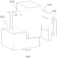
- the laser milling head 114 is connected to the connecting plate 113. In this way, when the connecting plate 113 moves in the vertical direction, the laser milling head 114 moves along therewith in the vertical direction.
- the horizontal beam 1061 can move along the two guide rails 105, that is, move along the Y direction; the moving terminal 112 can move along the horizontal beam 1061, that is, move along X direction; the connecting plate 113 moves up and down with respect to the connecting plate 113, that is, moves along the Z direction.
- the laser milling head 114 is movable in the three-dimension space.
- the laser milling head is provided therein with a cooling line, and the cooling line 115 is configured for allowing cooling water to flow through.
- the cooling line 115 is configured for allowing cooling water to flow through.
- the electron beam melting and laser milling composite 3D printing apparatus 1 further includes a metal powder recovering structure, and the metal powder recovering structure is configured for recovering the residual metal powder on the base 100 after machining. In this way, the cyclic utilization of the metal powder is facilitated.
- the metal powder recovering structure includes a recovering case 110, and the recovering case 110 defines a recovering cavity for receiving the recovered metal powder.
- the recovering case 110 is located below the base 100, and the base 100 defines a recovering opening therein, and the recovering opening is communicated with the recovering cavity of the recovering case 110 is further defined in the base 100.
- the residual metal powder on the base 100 can enter the recovering cavity of the recovering case 110 via the recovering opening, and the metal powder in the recovering cavity can be reused circularly after the residue therein is filtered out and removed.
- the recovering opening is arranged at a side edge of the machining platform 109.
- the recovering opening is arranged at the rear end of the machining platform 109.
- the recovering openings can be respectively defined at the front end and the rear end of the machining platform 109.
- the recovering opening may be arranged at two sides of the machining platform 109.
- the electron beam melting and laser milling composite 3D printing apparatus 1 further includes a machining chamber, and the machining chamber 107 has a machining space formed therein.
- the machining space is in a vacuum state, or is filled with inert gas.
- the base 100 is arranged in the machining space of the machining chamber; that is, the electron beam melting and laser milling composite 3D printing apparatus 1 is arranged in the machining space of the machining chamber.
- the metal electron beam melting 3D printing technology can obtain wider application space, and production and manufacturing of metal with high melting point can be provided with new methods and technical means.
Landscapes
- Engineering & Computer Science (AREA)
- Physics & Mathematics (AREA)
- Mechanical Engineering (AREA)
- Optics & Photonics (AREA)
- Plasma & Fusion (AREA)
- Chemical & Material Sciences (AREA)
- Manufacturing & Machinery (AREA)
- Materials Engineering (AREA)
- Powder Metallurgy (AREA)
Applications Claiming Priority (1)
| Application Number | Priority Date | Filing Date | Title |
|---|---|---|---|
| PCT/CN2014/095664 WO2016106603A1 (fr) | 2014-12-30 | 2014-12-30 | Appareil d'impression en 3d composite à fraisage laser et fusion par faisceaux d'électrons |
Publications (2)
| Publication Number | Publication Date |
|---|---|
| EP3228405A1 true EP3228405A1 (fr) | 2017-10-11 |
| EP3228405A4 EP3228405A4 (fr) | 2018-09-19 |
Family
ID=56283878
Family Applications (1)
| Application Number | Title | Priority Date | Filing Date |
|---|---|---|---|
| EP14909275.1A Withdrawn EP3228405A4 (fr) | 2014-12-30 | 2014-12-30 | Appareil d'impression en 3d composite à fraisage laser et fusion par faisceaux d'électrons |
Country Status (3)
| Country | Link |
|---|---|
| US (1) | US20160325383A1 (fr) |
| EP (1) | EP3228405A4 (fr) |
| WO (1) | WO2016106603A1 (fr) |
Cited By (1)
| Publication number | Priority date | Publication date | Assignee | Title |
|---|---|---|---|---|
| CN112475323A (zh) * | 2020-11-25 | 2021-03-12 | 北京星航机电装备有限公司 | 一种金属3d打印机成形缸系统 |
Families Citing this family (16)
| Publication number | Priority date | Publication date | Assignee | Title |
|---|---|---|---|---|
| CN104014793B (zh) * | 2014-05-15 | 2016-01-27 | 东莞市亚美精密机械配件有限公司 | 挤出式金属流3d打印机 |
| CN107486557B (zh) * | 2017-06-26 | 2023-07-04 | 西安铂力特增材技术股份有限公司 | 一种刮刀装置 |
| CN108789772B (zh) * | 2018-07-21 | 2024-10-22 | 佛山职业技术学院 | 一种陶瓷3d打印机 |
| US10894395B2 (en) | 2018-08-02 | 2021-01-19 | Ford Motor Company | Methods for making 3D parts using composite based additive manufacturing with perforated sheets and parts formed therefrom |
| US11426818B2 (en) | 2018-08-10 | 2022-08-30 | The Research Foundation for the State University | Additive manufacturing processes and additively manufactured products |
| KR102214404B1 (ko) | 2018-10-24 | 2021-02-09 | 한국철도기술연구원 | 3d 프린팅에 이용되는 파우더 적층 장치 및 이를 이용한 3d 프린팅 방법 |
| CN109848416A (zh) * | 2019-04-12 | 2019-06-07 | 上海应用技术大学 | 一种金属选区激光熔化用的烟尘过滤及粉末回收装置 |
| CN110014154B (zh) * | 2019-05-22 | 2024-04-05 | 宁波中久东方光电技术有限公司 | 激光熔覆镗削复合机床 |
| CN110064850B (zh) * | 2019-05-23 | 2024-06-07 | 重庆市捷锐数控设备有限公司 | 一种全自动开料机及其加工方法 |
| CN110315079B (zh) * | 2019-07-31 | 2024-03-26 | 西安增材制造国家研究院有限公司 | 一种增材制造装置及成形方法 |
| CN111940351A (zh) * | 2020-09-01 | 2020-11-17 | 晋中学院 | 一种3d打印设备金属粉末清理装置 |
| CN112355325B (zh) * | 2020-09-28 | 2022-12-16 | 西安增材制造国家研究院有限公司 | 一种基于随动粉缸的ebsm设备 |
| CN112496346A (zh) * | 2020-11-18 | 2021-03-16 | 江西鑫润材料科技有限公司 | 一种金属增材制造用针对合金粉末回收的装置 |
| CN112809020A (zh) * | 2020-12-22 | 2021-05-18 | 安徽省春谷3D打印智能装备产业技术研究院有限公司 | 一种具有筛分导料机构的3d金属打印机铺粉装置 |
| CN114346495B (zh) * | 2022-01-25 | 2023-11-03 | 深圳市鼎美达科技有限公司 | 一种激光打印用金属部件的镭雕设备 |
| CN117483808A (zh) * | 2023-11-10 | 2024-02-02 | 广州赛隆增材制造有限责任公司 | 粉床电子束3d打印设备及使用方法 |
Family Cites Families (22)
| Publication number | Priority date | Publication date | Assignee | Title |
|---|---|---|---|---|
| US3612815A (en) * | 1970-01-16 | 1971-10-12 | Smith Corp A O | Electron beam apparatus |
| US4541055A (en) * | 1982-09-01 | 1985-09-10 | Westinghouse Electric Corp. | Laser machining system |
| DE4113633C2 (de) * | 1991-04-26 | 1994-06-30 | Manfred Toeller | Bearbeitungsvorrichtung |
| US5398193B1 (en) * | 1993-08-20 | 1997-09-16 | Alfredo O Deangelis | Method of three-dimensional rapid prototyping through controlled layerwise deposition/extraction and apparatus therefor |
| JP2913263B2 (ja) * | 1995-07-07 | 1999-06-28 | 株式会社山和エンヂニアリング | 固形物粉砕乾燥装置 |
| JP3446618B2 (ja) * | 1998-08-26 | 2003-09-16 | 松下電工株式会社 | 金属粉末焼結部品の表面仕上げ方法 |
| US6401002B1 (en) * | 1999-04-29 | 2002-06-04 | Nanotek Instruments, Inc. | Layer manufacturing apparatus and process |
| JP3446733B2 (ja) * | 2000-10-05 | 2003-09-16 | 松下電工株式会社 | 三次元形状造形物の製造方法及びその装置 |
| JP3599054B2 (ja) * | 2002-09-30 | 2004-12-08 | 松下電工株式会社 | 三次元形状造形物の製造方法 |
| JP2005097692A (ja) * | 2003-09-25 | 2005-04-14 | Matsushita Electric Works Ltd | 三次元形状造形物の製造方法及びその装置 |
| US7777155B2 (en) * | 2007-02-21 | 2010-08-17 | United Technologies Corporation | System and method for an integrated additive manufacturing cell for complex components |
| JP5022846B2 (ja) * | 2007-09-20 | 2012-09-12 | 株式会社小森コーポレーション | 印刷されたシート状物への散粉装置 |
| CN201227612Y (zh) * | 2008-06-25 | 2009-04-29 | 上海胜狮冷冻货柜有限公司 | 集装箱箱外自动喷粉装置 |
| JP5456379B2 (ja) * | 2009-06-05 | 2014-03-26 | パナソニック株式会社 | 三次元形状造形物の製造方法 |
| KR101377832B1 (ko) * | 2009-08-25 | 2014-03-26 | 가부시끼가이샤 도시바 | 레이저 조사 장치 및 레이저 시공 방법 |
| EP2495056A1 (fr) * | 2011-03-01 | 2012-09-05 | Siemens Aktiengesellschaft | Procédé de frittage laser au moyen de vibrations et appareil |
| CN103561891B (zh) * | 2011-05-23 | 2015-11-25 | 松下电器产业株式会社 | 三维形状造型物的制造方法 |
| FR2984191B1 (fr) * | 2011-12-20 | 2014-01-10 | Michelin Soc Tech | Machine et procede pour la fabrication additive a base de poudre |
| US9566742B2 (en) * | 2012-04-03 | 2017-02-14 | Massachusetts Institute Of Technology | Methods and apparatus for computer-assisted spray foam fabrication |
| JP5599921B1 (ja) * | 2013-07-10 | 2014-10-01 | パナソニック株式会社 | 三次元形状造形物の製造方法 |
| CN104493165A (zh) * | 2014-12-30 | 2015-04-08 | 深圳市圆梦精密技术研究院 | 电子束熔融及激光铣削复合3d打印设备 |
| CN204524257U (zh) * | 2014-12-30 | 2015-08-05 | 深圳市圆梦精密技术研究院 | 电子束熔融及激光铣削复合3d打印设备 |
-
2014
- 2014-12-30 WO PCT/CN2014/095664 patent/WO2016106603A1/fr not_active Ceased
- 2014-12-30 US US15/110,557 patent/US20160325383A1/en not_active Abandoned
- 2014-12-30 EP EP14909275.1A patent/EP3228405A4/fr not_active Withdrawn
Cited By (1)
| Publication number | Priority date | Publication date | Assignee | Title |
|---|---|---|---|---|
| CN112475323A (zh) * | 2020-11-25 | 2021-03-12 | 北京星航机电装备有限公司 | 一种金属3d打印机成形缸系统 |
Also Published As
| Publication number | Publication date |
|---|---|
| EP3228405A4 (fr) | 2018-09-19 |
| US20160325383A1 (en) | 2016-11-10 |
| WO2016106603A1 (fr) | 2016-07-07 |
Similar Documents
| Publication | Publication Date | Title |
|---|---|---|
| EP3228405A1 (fr) | Appareil d'impression en 3d composite à fraisage laser et fusion par faisceaux d'électrons | |
| EP3228404A1 (fr) | Appareil d'impression en 3d composite à fraisage et fusion par faisceaux d'électrons multiples | |
| CN104493493B (zh) | 多轴铣削加工及激光熔融复合3d打印设备 | |
| CN104493165A (zh) | 电子束熔融及激光铣削复合3d打印设备 | |
| CN104476196A (zh) | 激光熔融及激光铣削复合3d打印设备 | |
| CN204524771U (zh) | 激光熔融及激光铣削复合3d打印设备 | |
| CN103726049B (zh) | 一种金属零件的激光增材制造方法和装备 | |
| EP3181272A1 (fr) | Procédé et dispositif d'usinage laser à espace d'alimentation de poudre synchrone et de formation tridimensionnelle | |
| CN103962557B (zh) | 一种可分离的选区快速成形设备 | |
| EP3536422B1 (fr) | Procédé de détection et de réparation de fabrication additive avec poudre | |
| CN111037052B (zh) | 电弧增材制造成形检测反馈补偿系统及检测反馈补偿方法 | |
| CN109202082B (zh) | 增材、等材、减材复合金属3d激光成形装置及其方法 | |
| EP3084129B1 (fr) | Appareil et procédé de fabrication additive | |
| CN203807559U (zh) | 一种金属零件的激光增材制造设备 | |
| CN204524788U (zh) | 多轴铣削加工及激光熔融复合3d打印设备 | |
| CN107262713A (zh) | 一种光内同轴送粉激光冲击锻打复合加工成形装置及方法 | |
| JP2009001900A (ja) | 三次元形状造形物の製造方法 | |
| CN113172242B (zh) | 一种选择性激光熔化成形实时监测装置及实现方法 | |
| CN104493492A (zh) | 激光选区熔化与铣削复合加工设备及加工方法 | |
| CN106624826B (zh) | 一种微束等离子3d打印与铣削复合加工设备与方法 | |
| CN104647762A (zh) | 切削加工式3d工业打印装置及打印方法 | |
| CN203791625U (zh) | 一种可分离的选区快速成形装置 | |
| CN108602261A (zh) | 三维形状造型物的制造方法 | |
| CN104526359A (zh) | 多个电子束熔融和铣削复合3d打印设备 | |
| US11229955B2 (en) | Method for manufacturing a part of electroconductive material by additive manufacturing |
Legal Events
| Date | Code | Title | Description |
|---|---|---|---|
| STAA | Information on the status of an ep patent application or granted ep patent |
Free format text: STATUS: THE INTERNATIONAL PUBLICATION HAS BEEN MADE |
|
| PUAI | Public reference made under article 153(3) epc to a published international application that has entered the european phase |
Free format text: ORIGINAL CODE: 0009012 |
|
| STAA | Information on the status of an ep patent application or granted ep patent |
Free format text: STATUS: REQUEST FOR EXAMINATION WAS MADE |
|
| 17P | Request for examination filed |
Effective date: 20160701 |
|
| AK | Designated contracting states |
Kind code of ref document: A1 Designated state(s): AL AT BE BG CH CY CZ DE DK EE ES FI FR GB GR HR HU IE IS IT LI LT LU LV MC MK MT NL NO PL PT RO RS SE SI SK SM TR |
|
| AX | Request for extension of the european patent |
Extension state: BA ME |
|
| DAX | Request for extension of the european patent (deleted) | ||
| RAP3 | Party data changed (applicant data changed or rights of an application transferred) |
Owner name: YUANMENG PRECISION TECHNOLOGY (SHENZHEN) INSTITUTE |
|
| A4 | Supplementary search report drawn up and despatched |
Effective date: 20180817 |
|
| RIC1 | Information provided on ipc code assigned before grant |
Ipc: B23K 37/02 20060101ALI20180810BHEP Ipc: B23P 23/04 20060101ALI20180810BHEP Ipc: B23K 26/08 20140101ALI20180810BHEP Ipc: B23K 15/00 20060101ALI20180810BHEP Ipc: B33Y 30/00 20150101ALI20180810BHEP Ipc: B22F 3/105 20060101AFI20180810BHEP Ipc: B23K 28/02 20140101ALI20180810BHEP Ipc: B23K 26/70 20140101ALI20180810BHEP Ipc: B23K 15/06 20060101ALI20180810BHEP Ipc: B23K 26/342 20140101ALI20180810BHEP Ipc: B23K 26/346 20140101ALI20180810BHEP Ipc: B23K 26/12 20140101ALI20180810BHEP |
|
| STAA | Information on the status of an ep patent application or granted ep patent |
Free format text: STATUS: EXAMINATION IS IN PROGRESS |
|
| 17Q | First examination report despatched |
Effective date: 20191024 |
|
| STAA | Information on the status of an ep patent application or granted ep patent |
Free format text: STATUS: THE APPLICATION HAS BEEN WITHDRAWN |
|
| 18W | Application withdrawn |
Effective date: 20191227 |