EP3228409A1 - Outil d'usinage - Google Patents
Outil d'usinage Download PDFInfo
- Publication number
- EP3228409A1 EP3228409A1 EP17159872.5A EP17159872A EP3228409A1 EP 3228409 A1 EP3228409 A1 EP 3228409A1 EP 17159872 A EP17159872 A EP 17159872A EP 3228409 A1 EP3228409 A1 EP 3228409A1
- Authority
- EP
- European Patent Office
- Prior art keywords
- cross
- cooling channel
- diameter
- tool
- curve segment
- Prior art date
- Legal status (The legal status is an assumption and is not a legal conclusion. Google has not performed a legal analysis and makes no representation as to the accuracy of the status listed.)
- Pending
Links
Images


Classifications
-
- B—PERFORMING OPERATIONS; TRANSPORTING
- B23—MACHINE TOOLS; METAL-WORKING NOT OTHERWISE PROVIDED FOR
- B23B—TURNING; BORING
- B23B51/00—Tools for drilling machines
- B23B51/06—Drills with lubricating or cooling equipment
-
- B—PERFORMING OPERATIONS; TRANSPORTING
- B23—MACHINE TOOLS; METAL-WORKING NOT OTHERWISE PROVIDED FOR
- B23B—TURNING; BORING
- B23B51/00—Tools for drilling machines
- B23B51/02—Twist drills
-
- B—PERFORMING OPERATIONS; TRANSPORTING
- B23—MACHINE TOOLS; METAL-WORKING NOT OTHERWISE PROVIDED FOR
- B23P—METAL-WORKING NOT OTHERWISE PROVIDED FOR; COMBINED OPERATIONS; UNIVERSAL MACHINE TOOLS
- B23P15/00—Making specific metal objects by operations not covered by a single other subclass or a group in this subclass
- B23P15/28—Making specific metal objects by operations not covered by a single other subclass or a group in this subclass cutting tools
- B23P15/32—Making specific metal objects by operations not covered by a single other subclass or a group in this subclass cutting tools twist-drills
-
- B—PERFORMING OPERATIONS; TRANSPORTING
- B23—MACHINE TOOLS; METAL-WORKING NOT OTHERWISE PROVIDED FOR
- B23B—TURNING; BORING
- B23B2250/00—Compensating adverse effects during turning, boring or drilling
- B23B2250/12—Cooling and lubrication
-
- B—PERFORMING OPERATIONS; TRANSPORTING
- B23—MACHINE TOOLS; METAL-WORKING NOT OTHERWISE PROVIDED FOR
- B23B—TURNING; BORING
- B23B2251/00—Details of tools for drilling machines
- B23B2251/18—Configuration of the drill point
Definitions
- the present invention relates to a cutting tool, in particular a drilling tool, with a cooling channel according to the preamble of claim 1.
- the drilling tool is cooled with a coolant or lubricated with a lubricating emulsion.
- the coolant or the lubricant can be brought to the cutting edge of the drilling tool in a variety of ways. For example, arranged in the drilling tool internal fluid channels, which extend from the clamping shaft to the drill bit. Alternatively, the coolant or lubricant can also be fed directly to the drill via a hose from the outside.
- the arrangement of the fluid channels, which extend to the drill tip, usually the problem that the drill is greatly weakened. It can lead in particular to fractures in the drill.
- the invention has for its object to provide a cutting tool, which overcomes the disadvantages of the prior art.
- the tool should be less susceptible to fractures.
- a cutting tool comprises a blade extending along a central axis Clamping portion, a the chucking section adjoining a nominal diameter having cutting section and at least one cooling channel.
- the cooling channel preferably runs in the clamping section and in the cutting section.
- the cross-sectional shape of the cooling channel is arranged in a cross-sectional area of the respective section, ie the clamping section and / or the cutting section or chip section, in which the comparison stress has the lowest possible value for a machining load.
- the cross-sectional shape of the cooling channel is defined by an inner curve segment, a spaced-apart outer curve segment and two tangents connecting the two curve segments.
- a third embodiment of the invention is characterized in that the cross-sectional shape of the cooling channel is arranged in a cross-sectional area of the respective section, ie the clamping section and / or the cutting section or the chip section, in which the comparison voltage has the lowest possible value for a machining load in that the cross-sectional shape of the cooling channel is defined by an inner curve segment, a spaced-apart outer curve segment and two tangents connecting the two curve segments.
- the cross-sectional shape in a region in which the comparison voltage has the lowest possible value, the cross-sectional shape can be optimized to the voltages occurring during processing.
- the cross-sectional shape extends in areas in which only a correspondingly low voltage occurs.
- the shape as such has a favorable effect on the stresses occurring in the tool.
- the voltage peaks, which favor a fracture can be reduced.
- the tool becomes more robust.
- the third embodiment combines the advantages of the first and second embodiments.
- reference voltage is understood to mean a fictitious uniaxial mechanical stress which represents a similar material stress as a real multiaxial stress state.
- comparative stress is known in the technical mechanics, in particular strength theory, to the person skilled in the art. Particularly preferably, the reference voltage is understood as the reference voltage according to Mises.
- cross-sectional shape is understood to mean the shape of the cooling channel, which is visible in a cross-sectional area which extends transversely, ie at right angles, to the central axis.
- cross-sectional area is understood to mean a region of the cutting tool in transverse cross-section, that is to say at right angles to the central axis. In this area, the comparison voltage has the lowest possible value.
- the comparison stress in said cross-sectional area is in the range of 10 to 25% of the maximum reference stress occurring in the tool.
- the cooling channel is therefore particularly preferably arranged in a cross-sectional area in which the comparison voltage is in the range from 10 to 25%. This particular under the proviso that the cross-sectional area outside an inner Limiting diameter of at least 10% or at least 15% or at least 20%.
- the comparison with the maximum reference voltage preferably relates to the same cutting plane.
- the cross-sectional shape of the cooling channels fills the said cross-sectional area, in particular with the proviso that the cross-sectional shape is outside an inner limiting diameter of at least 10% or at least 15% or at least 20%, maximum.
- the cross-sectional area is optimized over the cross-sectional area in which the reference stress is as low as possible. In this way, the largest possible cross-sectional area of the cooling channel can be achieved, whereby the flow of the coolant can be improved.
- the cross-sectional shape of the cooling channels fills said cross-sectional area, in particular under the proviso that the cross-sectional shape is outside at least 10% or at least 15% or at least 20%, at least over 75%, more preferably at least over 80%. Although this slightly reduces the cross-sectional area of the cooling passage, the mechanical stability can be improved.
- the curve segment is defined by a circle segment.
- the curve segment can be defined by an ellipse.
- the inner curve segment and the outer curve segment may have different geometric shapes.
- the outer curve segment has approximately the shape of a straight line, which is curved at the ends, with the tangents joining the curvature. With such a form, a kind of triangle is provided.
- the diameter of the inner curve segment is smaller than the diameter of the outer curve segment.
- the curve segments to the interior of the cooling channel are concave to Interior of the cooling channel formed.
- the shape of the cross-section thus has essentially the shape of a drop.
- the centers of the curve segments lie on a common straight line extending to and through the central axis.
- the cross-sectional shape of the cooling channel in the cutting section lies within an outer limiting diameter, which corresponds to a maximum of 70% or at most 80% of the nominal diameter of the tool.
- the cross-sectional shape of the cooling channel in the cutting section is outside an inner limiting diameter which corresponds to at least 10% or at least 15% or at least 20% of the nominal diameter of the tool.
- a third variant is characterized in that the cross-sectional shape of the cooling channel in the cutting section within an outer limiting diameter corresponding to a maximum of 70% or at most 80% of the nominal diameter of the tool, and / or that the cross-sectional shape of the cooling channel in the cutting section outside an inner limiting diameter, the at least 10% or at least 15% or at least 20% of the nominal diameter of the tool.
- the center of the inner curve segment and the center of the outer curve segment are at a distance from each other.
- the position of the center of the inner curve segment is chosen so that it does not lie in the region between the center of the outer curve segment and the edge of the outer curve segment.
- the position of the outer curve segment is chosen so that this is not in the area between the center of the inner curve segment and the edge of the inner curve segment lies.
- said distance between the centers is in the range of 4/8 to 6/8, more preferably 5/8 of the diameter of the outer curve segment.
- the distance substantially corresponds to the diameter of the inner curve segment.
- the diameter of the inner curve segment is in the range of 4/8 to 6/8, in particular 5/8, of the diameter of the outer curve segment.
- the diameter of the outer curve segment is greater than that of the inner curve segment.
- the clear width of the cross section of the cooling channel increases with increasing distance from the central axis.
- the chip-removing tool is a twist drill or a milling tool or a reamer or a special tool.
- a method for producing a cutting tool according to the above description is characterized in that in a step of determining the cross-sectional shape, a stress analysis of the tool under a predetermined load is made, wherein the cross-sectional area in which the comparison stress in a machining load has the lowest possible value should, is determined.
- the cross-sectional area of the cooling channel is optimized for the cross-sectional area.
- a blank is used to produce a cutting tool as described above, wherein the blank comprises at least one cooling channel as described above.
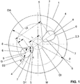
- the cutting tool 1 comprises a clamping section 2 extending along a central axis M, a cutting section 3 adjoining the clamping section 2 and at least one cooling channel 4.
- the cross section according to the FIG. 1 may represent both the cross section of the clamping section 2 and those of the cutting section 3.
- the clamping section 2 is used for clamping the tool 1 in a machine tool and the cutting section 3 is used for machining a workpiece.
- cooling channels 4 are arranged.
- the cooling channels 4 serve to supply cooling and / or lubricants to the cutting section 3.
- the cooling channels 4 preferably extend through the clamping section 2 and through the cutting section 3.
- the two cooling channels are diametrically opposite each other with respect to the central axis M.
- more than two cooling channels may be arranged, which are then not necessarily diametrically opposite. Preferably, however, the angular distance between all cooling channels is the same.
- the cross-sectional shape of the cooling passage 4 is in a cross-sectional area Q of the respective one Section arranged in which the comparison voltage has a minimum value in a machining load.
- the cross-sectional area Q is in the FIG. 1 shown with a dashed line.
- the dashed line runs schematically and may also have a different shape.
- the arrangement of the cooling channel 4 in a cross-sectional area Q in the clamping section 2 or in the cutting section 3 has the advantage that the cross-sectional shape of the cooling channel can be optimized so that it lies in places which are subjected to low mechanical stress. As a result, the overall stability of the tool can be massively improved.
- the cross-sectional shape of the cooling channel 4 is defined in the embodiment shown by an inner curve segment 5, here a circle segment, and a spaced therefrom outboard curve segment 6, here circle segment, and by two the two curve segments 5, 6 connecting tangents 7.
- the tangents are tangent to the corresponding curve segments.
- a closed polyline is provided, which defines the cross-sectional shape of the cooling channel 4.
- the cross-sectional shape of the cooling channel 4 in the embodiment shown has a teardrop-shaped configuration.
- the curve segment 5 does not necessarily have to be a circular segment.
- the curve segment 5 can also be elliptical or have a different shape.
- the comparison stress in said cross-sectional area is preferably in the range of 10 to 25% of the maximum reference stress, in particular under the proviso that the cross-sectional area is outside an inner limiting diameter DI of at least 10% or at least 15% or at least 20%.
- the tension conditions are in the FIG. 7 shown in more detail.
- the cross-sectional shape of the cooling channel fills said cross-sectional area Q, in which the comparison stress has the lowest possible value in the case of machining, preferably maximally. This is particularly the case that the cross-sectional shape is outside an inner limiting diameter DI of at least 10% or at least 15% or at least 20%. This means that the cross-sectional area of the cooling channel 4 can be optimized, so that the volume flow to be passed through the cooling channel 4 can be maximized.
- the cross-sectional shape of the cooling channel 4 may fill the said cross-sectional area Q at least 75%, particularly preferably at least 80%. This is particularly the case that the cross-sectional shape is outside an inner limiting diameter DI of at least 10% or at least 15% or at least 20%. Again, a maximization of the cross-sectional area of the cross-sectional shape is sought, in addition, the tool is more robust against fractures due to the lower weakening.
- the diameter D1 of the inner curve segment 5 is here smaller than the diameter D2 of the outer curve segment 6.
- the curve segments 5, 6 are concave to the interior of the cooling channel 4. Thus, the above-mentioned drop shape is created.
- the straight line G extends radially to the central axis M and here extends through the central axis M therethrough.
- the centers of all the circle segments lie on a common straight line.
- this is not necessarily the case.
- the cross-sectional shape of the cooling channel 4 lies in particular in the cutting section 3 within an outer limiting diameter DA.
- the outer limiting diameter DA is in the FIG. 1 shown schematically.
- the outer limiting diameter DA corresponds to a maximum of 70% or a maximum of 80% of the nominal diameter DN of the tool 1.
- the arrangement within this limiting diameter DA ensures that against the outside, ie between the outermost point of the outer circle segment 6 and the nominal diameter sufficient material thickness is present ,
- the cross-sectional shape of the cooling channel 4 in the cutting section 3 is outside an inner limiting diameter DI.
- the limiting diameter DI is in the FIG. 1 also marked.
- the limiting diameter DI corresponds to at least 10% or at least 15% or at least 20% of the nominal diameter of the tool.
- the center 8 of the inner circle segment 5 and the center 9 of the outer circle segment 6 are at a distance s from each other.
- the distance s is chosen such that the circular segments 5, 6 can be connected to one another via the tangent 7.
- the distance S between the centers 8, 9 of the two circle segments 5, 6 substantially corresponds to the diameter D1 of the inner circle segment 5.
- the dimension describes the distance between the centers of the outer curve segments 6- Preferably, this distance is in the range of 40% to 70% of the nominal diameter, in particular in the range of 45% to 55% of the nominal diameter.
- the dimension L is the minimum distance between the two cooling channels.
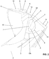
- FIGS. 2 to 5 show the cutting tool 1 in the form of a twist drill.
- the cooling channel 4 opens here via the free surface 10, which adjoins the main cutting edge 11.
- the cross section of the cooling channel 4 is completely within the free surface 10. This is of the Figures 2 and 3 seen.
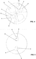
- FIGS. 4 and 5 show corresponding views of the twist drill in the direction of the central axis M from the front ( FIG. 4 ) and from behind ( FIG. 5 ).
- the cross section of the cooling channel 4 with respect to cross-sectional area and cross-sectional shape over the entire length of the cooling channel 4 is constant in cross section.
- the position of the cooling channel 4 with respect to the central axis M over the entire length of the cooling channel is preferably constant. That is, the distance of the cooling channel 4 to the central axis M does not change over the entire length of the cutting tool 1.
- the cooling channels are preferably arranged in a helical manner, these having at least in the cutting section 3, the same pitch as the spiral grooves of the twist drill.
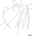
- FIG. 6 another embodiment of the cutting tool 1 in the form of a twist drill is shown.
- the difference to the FIGS. 2 to 5 Is that the cross section of the cooling channel 4 opens into the open both on the free surface 10 and on the flute 12.
Landscapes
- Engineering & Computer Science (AREA)
- Mechanical Engineering (AREA)
- Drilling Tools (AREA)
Applications Claiming Priority (1)
| Application Number | Priority Date | Filing Date | Title |
|---|---|---|---|
| CH00448/16A CH712323A1 (de) | 2016-04-07 | 2016-04-07 | Spanabhebendes Werkzeug mit mindestens einem Kühlkanal. |
Publications (1)
| Publication Number | Publication Date |
|---|---|
| EP3228409A1 true EP3228409A1 (fr) | 2017-10-11 |
Family
ID=55752125
Family Applications (1)
| Application Number | Title | Priority Date | Filing Date |
|---|---|---|---|
| EP17159872.5A Pending EP3228409A1 (fr) | 2016-04-07 | 2017-03-08 | Outil d'usinage |
Country Status (3)
| Country | Link |
|---|---|
| US (1) | US10442012B2 (fr) |
| EP (1) | EP3228409A1 (fr) |
| CH (1) | CH712323A1 (fr) |
Families Citing this family (6)
| Publication number | Priority date | Publication date | Assignee | Title |
|---|---|---|---|---|
| US12303986B2 (en) | 2018-12-26 | 2025-05-20 | Mitsubishi Materials Corporation | Rotating tool with coolant hole |
| JP7463689B2 (ja) * | 2018-12-26 | 2024-04-09 | 三菱マテリアル株式会社 | クーラント穴付き回転工具 |
| US10814406B1 (en) * | 2019-04-24 | 2020-10-27 | Raytheon Technologies Corporation | Internal cooling passages for rotating cutting tools |
| WO2022162774A1 (fr) * | 2021-01-27 | 2022-08-04 | 住友電工ハードメタル株式会社 | Mèche |
| CN116551067B (zh) * | 2023-06-06 | 2023-12-01 | 肇庆创富新材料科技股份有限公司 | 一种高强度的建筑用铝模板生产加工装置 |
| US20250256339A1 (en) * | 2024-02-09 | 2025-08-14 | Kennametal Inc. | Rotary cutting tools with through coolant channels |
Citations (4)
| Publication number | Priority date | Publication date | Assignee | Title |
|---|---|---|---|---|
| DE3314349A1 (de) * | 1983-04-20 | 1984-10-25 | Gühring, Gottlieb, 7470 Albstadt | Bohrungs-nachbearbeitungswerkzeug |
| JPS6442816U (fr) * | 1987-09-09 | 1989-03-14 | ||
| WO2004056519A2 (fr) * | 2002-12-19 | 2004-07-08 | Gühring, Jörg | Geometrie de canal de refroidissement |
| EP2952278A1 (fr) * | 2013-01-29 | 2015-12-09 | OSG Corporation | Foret |
Family Cites Families (10)
| Publication number | Priority date | Publication date | Assignee | Title |
|---|---|---|---|---|
| US2541849A (en) * | 1946-10-05 | 1951-02-13 | Villeneuve Louis Jean Albert | Process for manufacturing hollow tools |
| AT279998B (de) * | 1967-05-09 | 1970-03-25 | Rohde & Doerrenberg | Verfahren zum Herstellen von Spiralbohrern od.ähnl Werkzeugen sowie nach dem Verfahren hergestellter Spiralbohrer |
| SU1276446A2 (ru) * | 1984-12-03 | 1986-12-15 | Ленинградский Ордена Ленина И Ордена Красного Знамени Механический Институт | Спиральное сверло |
| DE3629035A1 (de) * | 1986-08-27 | 1988-03-10 | Stellram Gmbh | Einteiliges spanabhebendes werkzeug |
| JP4070581B2 (ja) * | 2002-11-06 | 2008-04-02 | 日立ツール株式会社 | スパイラルホール付ドリル |
| KR20050085843A (ko) * | 2002-12-19 | 2005-08-29 | 귀링 요르크 | 코일형 냉각 채널을 구비한 소결 블랭크 |
| JP5447129B2 (ja) * | 2009-06-15 | 2014-03-19 | 三菱マテリアル株式会社 | クーラント穴付きドリル |
| DE102012001732B4 (de) * | 2012-01-31 | 2022-11-10 | Kennametal Inc. | Werkzeugkopf für ein modulares Schaftwerkzeug, Schaftwerkzeug mit einem solchen Werkzeugkopf sowie Herstellungsverfahren für einen Werkzeugkopf |
| DE102013205056A1 (de) * | 2013-03-21 | 2014-09-25 | Gühring KG | Mehrschneidiges Bohrwerkzeug mit innenliegenden Kühlkanälen |
| JP6268809B2 (ja) * | 2013-08-22 | 2018-01-31 | 三菱マテリアル株式会社 | ドリル |
-
2016
- 2016-04-07 CH CH00448/16A patent/CH712323A1/de unknown
-
2017
- 2017-03-08 EP EP17159872.5A patent/EP3228409A1/fr active Pending
- 2017-04-06 US US15/480,936 patent/US10442012B2/en active Active
Patent Citations (4)
| Publication number | Priority date | Publication date | Assignee | Title |
|---|---|---|---|---|
| DE3314349A1 (de) * | 1983-04-20 | 1984-10-25 | Gühring, Gottlieb, 7470 Albstadt | Bohrungs-nachbearbeitungswerkzeug |
| JPS6442816U (fr) * | 1987-09-09 | 1989-03-14 | ||
| WO2004056519A2 (fr) * | 2002-12-19 | 2004-07-08 | Gühring, Jörg | Geometrie de canal de refroidissement |
| EP2952278A1 (fr) * | 2013-01-29 | 2015-12-09 | OSG Corporation | Foret |
Also Published As
| Publication number | Publication date |
|---|---|
| CH712323A1 (de) | 2017-10-13 |
| US20170291229A1 (en) | 2017-10-12 |
| US10442012B2 (en) | 2019-10-15 |
Similar Documents
| Publication | Publication Date | Title |
|---|---|---|
| EP3228409A1 (fr) | Outil d'usinage | |
| DE102010006796B4 (de) | Verfahren zur Herstellung eines Bohrers, sowie Bohrer | |
| DE69729467T2 (de) | Kaltformgewindebohrer mit inner diameter feinbearbeitungseinsatz und dessen herstellungsmethode | |
| DE112015002125B4 (de) | Fräskopf sowie Werkzeug mit Fräskopf | |
| EP1864736B1 (fr) | Outil de production de filetage doté d'une jonction de bordure | |
| DE102006026853A1 (de) | Spanabhebendes Werkzeug | |
| EP3150315B1 (fr) | Fraise à queue | |
| WO2015193173A1 (fr) | Outil de coupe à rotation | |
| DE102019102726A1 (de) | Bohrwerkzeug und Verfahren zur Erzeugung einer Bohrung | |
| EP2419234B1 (fr) | Outil de fraisage doté d'une alimentation en agent de refroidissement/de lubrification située à l'intérieur de celui-ci | |
| EP3797911A1 (fr) | Fraise à queue et son procédé de fabrication | |
| EP3846957A1 (fr) | Foret | |
| EP1858670A1 (fr) | Dispositif de transmission de couple de rotation a siege de serrage entre une partie menante et une partie menee, en particulier outil de vissage | |
| DE112008004051T5 (de) | Spiralgewindebohrer | |
| DE102015115548B4 (de) | Stabmesserkopf | |
| DE102020004179B4 (de) | Schraubenelement und System bestehend aus einem Schraubendreher und mindestens einem solchen Schraubenelement | |
| EP2868416B1 (fr) | Procédé de formation d'un trou et dispositif de formation de trou correspondant | |
| DE102014201899B4 (de) | Dentalinstrument | |
| DE102015108649A1 (de) | Bohrwerkzeug | |
| EP2915613B1 (fr) | Foret à trou transversal | |
| DE112006004174T5 (de) | Spiralnut-Gewindeschneider | |
| DE102015116624B4 (de) | Schaftfräser | |
| WO2017198265A1 (fr) | Fraise à queue | |
| EP3600738B1 (fr) | Outil de perçage | |
| EP3944918A1 (fr) | Fraise à chanfreiner |
Legal Events
| Date | Code | Title | Description |
|---|---|---|---|
| PUAI | Public reference made under article 153(3) epc to a published international application that has entered the european phase |
Free format text: ORIGINAL CODE: 0009012 |
|
| STAA | Information on the status of an ep patent application or granted ep patent |
Free format text: STATUS: THE APPLICATION HAS BEEN PUBLISHED |
|
| AK | Designated contracting states |
Kind code of ref document: A1 Designated state(s): AL AT BE BG CH CY CZ DE DK EE ES FI FR GB GR HR HU IE IS IT LI LT LU LV MC MK MT NL NO PL PT RO RS SE SI SK SM TR |
|
| AX | Request for extension of the european patent |
Extension state: BA ME |
|
| STAA | Information on the status of an ep patent application or granted ep patent |
Free format text: STATUS: REQUEST FOR EXAMINATION WAS MADE |
|
| 17P | Request for examination filed |
Effective date: 20180223 |
|
| RBV | Designated contracting states (corrected) |
Designated state(s): AL AT BE BG CH CY CZ DE DK EE ES FI FR GB GR HR HU IE IS IT LI LT LU LV MC MK MT NL NO PL PT RO RS SE SI SK SM TR |
|
| STAA | Information on the status of an ep patent application or granted ep patent |
Free format text: STATUS: EXAMINATION IS IN PROGRESS |
|
| 17Q | First examination report despatched |
Effective date: 20210406 |
|
| RAP1 | Party data changed (applicant data changed or rights of an application transferred) |
Owner name: MIKRON SWITZERLAND AG |
|
| RAP3 | Party data changed (applicant data changed or rights of an application transferred) |
Owner name: MIKRON SWITZERLAND AG |