EP3228417A1 - Procédé et dispositif de traitement laser de structures monolithiques utilisées dans le domaine du pesage - Google Patents
Procédé et dispositif de traitement laser de structures monolithiques utilisées dans le domaine du pesage Download PDFInfo
- Publication number
- EP3228417A1 EP3228417A1 EP17162860.5A EP17162860A EP3228417A1 EP 3228417 A1 EP3228417 A1 EP 3228417A1 EP 17162860 A EP17162860 A EP 17162860A EP 3228417 A1 EP3228417 A1 EP 3228417A1
- Authority
- EP
- European Patent Office
- Prior art keywords
- laser beam
- processing
- machining head
- head
- machining
- Prior art date
- Legal status (The legal status is an assumption and is not a legal conclusion. Google has not performed a legal analysis and makes no representation as to the accuracy of the status listed.)
- Granted
Links
Images
Classifications
-
- B—PERFORMING OPERATIONS; TRANSPORTING
- B23—MACHINE TOOLS; METAL-WORKING NOT OTHERWISE PROVIDED FOR
- B23K—SOLDERING OR UNSOLDERING; WELDING; CLADDING OR PLATING BY SOLDERING OR WELDING; CUTTING BY APPLYING HEAT LOCALLY, e.g. FLAME CUTTING; WORKING BY LASER BEAM
- B23K26/00—Working by laser beam, e.g. welding, cutting or boring
- B23K26/36—Removing material
- B23K26/40—Removing material taking account of the properties of the material involved
-
- B—PERFORMING OPERATIONS; TRANSPORTING
- B23—MACHINE TOOLS; METAL-WORKING NOT OTHERWISE PROVIDED FOR
- B23K—SOLDERING OR UNSOLDERING; WELDING; CLADDING OR PLATING BY SOLDERING OR WELDING; CUTTING BY APPLYING HEAT LOCALLY, e.g. FLAME CUTTING; WORKING BY LASER BEAM
- B23K26/00—Working by laser beam, e.g. welding, cutting or boring
- B23K26/08—Devices involving relative movement between laser beam and workpiece
- B23K26/0869—Devices involving movement of the laser head in at least one axial direction
- B23K26/0876—Devices involving movement of the laser head in at least one axial direction in at least two axial directions
-
- B—PERFORMING OPERATIONS; TRANSPORTING
- B23—MACHINE TOOLS; METAL-WORKING NOT OTHERWISE PROVIDED FOR
- B23K—SOLDERING OR UNSOLDERING; WELDING; CLADDING OR PLATING BY SOLDERING OR WELDING; CUTTING BY APPLYING HEAT LOCALLY, e.g. FLAME CUTTING; WORKING BY LASER BEAM
- B23K26/00—Working by laser beam, e.g. welding, cutting or boring
- B23K26/08—Devices involving relative movement between laser beam and workpiece
- B23K26/10—Devices involving relative movement between laser beam and workpiece using a fixed support, i.e. involving moving the laser beam
- B23K26/103—Devices involving relative movement between laser beam and workpiece using a fixed support, i.e. involving moving the laser beam the laser beam rotating around the fixed workpiece
- B23K26/106—Devices involving relative movement between laser beam and workpiece using a fixed support, i.e. involving moving the laser beam the laser beam rotating around the fixed workpiece inside the workpiece
-
- B—PERFORMING OPERATIONS; TRANSPORTING
- B23—MACHINE TOOLS; METAL-WORKING NOT OTHERWISE PROVIDED FOR
- B23K—SOLDERING OR UNSOLDERING; WELDING; CLADDING OR PLATING BY SOLDERING OR WELDING; CUTTING BY APPLYING HEAT LOCALLY, e.g. FLAME CUTTING; WORKING BY LASER BEAM
- B23K26/00—Working by laser beam, e.g. welding, cutting or boring
- B23K26/36—Removing material
- B23K26/361—Removing material for deburring or mechanical trimming
-
- B—PERFORMING OPERATIONS; TRANSPORTING
- B23—MACHINE TOOLS; METAL-WORKING NOT OTHERWISE PROVIDED FOR
- B23K—SOLDERING OR UNSOLDERING; WELDING; CLADDING OR PLATING BY SOLDERING OR WELDING; CUTTING BY APPLYING HEAT LOCALLY, e.g. FLAME CUTTING; WORKING BY LASER BEAM
- B23K2101/00—Articles made by soldering, welding or cutting
- B23K2101/20—Tools
-
- B—PERFORMING OPERATIONS; TRANSPORTING
- B23—MACHINE TOOLS; METAL-WORKING NOT OTHERWISE PROVIDED FOR
- B23K—SOLDERING OR UNSOLDERING; WELDING; CLADDING OR PLATING BY SOLDERING OR WELDING; CUTTING BY APPLYING HEAT LOCALLY, e.g. FLAME CUTTING; WORKING BY LASER BEAM
- B23K2101/00—Articles made by soldering, welding or cutting
- B23K2101/28—Beams
-
- G—PHYSICS
- G01—MEASURING; TESTING
- G01G—WEIGHING
- G01G21/00—Details of weighing apparatus
- G01G21/24—Guides or linkages for ensuring parallel motion of the weigh-pans
- G01G21/244—Guides or linkages for ensuring parallel motion of the weigh-pans combined with flexure-plate fulcrums
-
- G—PHYSICS
- G01—MEASURING; TESTING
- G01G—WEIGHING
- G01G7/00—Weighing apparatus wherein the balancing is effected by magnetic, electromagnetic, or electrostatic action, or by means not provided for in the preceding groups
- G01G7/02—Weighing apparatus wherein the balancing is effected by magnetic, electromagnetic, or electrostatic action, or by means not provided for in the preceding groups by electromagnetic action
Definitions
- the present invention relates to a method and a device for material-removing laser processing monolithic structures, which are provided in particular for weighing applications.
- monolithic structures also called “monoblocks”
- Such monolithic structures often contain, after completion, one or more levers, tie rods or parallel links which have been cut free (milled, eroded or the like) in the monolithic structure and only material thinning with other areas of the monoblock acting as a joint keep in touch.
- a machining accuracy in the submillimeter is required, and in particular acting as joints thin areas must be processed with high precision.
- a monoblock to be processed extends in three spatial directions, of which the width is to be referred to below as the Z direction.
- a thin spot is formed, for example, by two parallel, running in the Z direction cylindrical recesses or holes, which have only a small material web between their lateral surfaces - the thin point. Both the thickness of such a thin location transverse to the Z-direction, as well as their length in the Z-direction determines their stiffness, which has a significant influence on the transmitted from the individual levers and finally to be measured forces.
- From the DE 10 2013 108 097 A1 discloses a method for manufacturing a force measuring body, in which material is removed by means of a laser in the vicinity of an existing thin point in order to influence the deflection behavior of a coupled via the thin point lever.
- a monolithic weighing system in which a slit aperture is introduced by means of a laser in a lever arm, which can be done for example via a mirror.
- the laser processing of monolithic structures produces a different processing surface than with conventional machining methods (for example, drilling, milling). Such machining processes generally produce a bright, glossy processing surface.
- material is removed at a plurality of adjacent points, resulting in a less shiny substructure with some roughness.
- the object of the invention was therefore to provide a method and a device which allows the material-removing laser processing in hard to reach places within monolithic structures.
- the object is achieved by a method according to claim 1 and a device according to claim 12. Further advantageous embodiments emerge from the subclaims.
- the machining head may expediently also be movable perpendicularly to the Z-direction, that is to say in the X or Y direction, and also pivoting about these axes may facilitate the implementation of the machining method.
- the movement of the machining head or the deflecting means held thereby can take place alternately, permanently or temporarily.
- a longitudinal processing of the monolithic structure is obtained by moving the machining head in the Z direction, for the purpose of the most uniform, as long as possible over the entire desired processing width (for example over the entire width of the monolithic structure) in one go.
- a thin area remaining between two circular material recesses can be produced or machined, for example, by the machining head respectively traversing the entire Z length of the thin spot at a specific pivoting angle about the Z axis, wherein the pivot angle changes slightly before the next stroke in the Z direction to create or process another area of the circular recess.
- the processing could also be done by at a certain immersion depth (Z position) the total required for the generation of the rounding pivoting angle is driven by turning the machining head before the head is moved to the next Z position, to there again the total required To retract swivel angle.
- Z position immersion depth
- the laser beam strikes the deflection means, which deflect it from the Z direction by preferably 90 ° so that the deflected laser beam approximately perpendicular to the Z direction emerges laterally from the machining head and reaches a target point to be machined.
- the laser can be passed through a lateral opening of the machining head through to the outside.
- the machining head could be open at the front end, with the deflection means protruding somewhat beyond the front end in the Z direction, so that the then deflected laser beam is beyond the front end is distracted to the side.
- the deflection of the laser beam through a lateral opening of the machining head has the advantage that this opening need only be insignificantly larger than the laser beam passing through, so that the undesired ingress of dirt or material removal into the interior of the Processing head is avoided or prevented. Even with the screening described below, a lateral opening in a size of, for example, 1 mm 2 is sufficient.
- a front open machining head is easier to manufacture and in particular allows a simplified suction of material removal, as will be seen.
- the deflection or the outer wall of the machining head As close as possible to the target to be machined.
- the distance between the deflection means or the outside of the machining head is preferably less than 5 mm, more preferably less than 2 mm. Most preferably, the distance is below 0.5 mm.
- An extraction leading into the machining head is brought particularly close to the respective target point to be machined by this reduced distance and can accordingly be vacuumed effectively.
- a rounded around the Z direction recess eg., One side of a thin area
- it is advisable to rounded the machining head in the region of the laser exit for example.
- the machining head can be brought close to the rounding in the monoblock and forms with her a thin annular gap section for a good suction effect.
- the deposition of material on the processing surfaces, in particular the thin points of joints, can be well avoided.
- a family of target points is to be processed by the method. It can be a group of points that form only a single point (zero-dimensional) in space, a straight or curved line (one-dimensional), a flat or curved surface (two-dimensional) and even an arbitrarily defined volume (three-dimensional). At least some of the target points of a predetermined set of target points are approached successively by the laser by moving the machining head in the Z-direction or pivoted about the Z-axis. Thus, points or areas of surfaces can be reworked or three-dimensional recesses produced, for example, to cut a thin spot to a predeterminable length in the Z direction. Furthermore, material can be removed along lines or from grooves which, when the pivoting movement of the laser about the Z-axis and the Z-direction method are superimposed, can have an almost freely selectable spatial form.
- the method according to the invention can preferably be used for machining a joint structure, in particular in order to be able to work out or process the thin location of a joint.
- a joint may be part of a lever, a bearing, a coupling rod or a parallelogram, in which it depends on high-precision machining in the micron range.
- the method can also be used for processing other areas of a monolithic structure in which micron-accurate material removal is not required, but which are not accessible from outside the block or only by additionally provided lateral recesses for classical machining processes, for example. Lever To create or further edit undercuts or other recesses.
- the laser is first generated as a raw beam from a laser source, which in turn may be stationary or connected to the machining head.
- the raw beam (L ') generated by the laser source is passed before reaching the deflection means according to the invention by a fixed or movable with the processing head optical unit to set the intended for processing laser beam (L).
- Adjustment is to be understood here in particular as focusing, which takes place in such a way that the laser beam taking into account the deflecting means is bundled so that it has a preferred energy density at the location of each destination to be processed.
- the optical unit may be an arrangement of optical elements of laser technology known per se in the art (lenses, filters, diaphragms, etc.). If necessary, individual or all of these elements can be moved or adjusted via actuators (for example piezoelectric elements), for which purpose the actuators can receive suitable control signals from a higher-order control unit or output to the latter via encoders.
- actuators for example piezoelectric elements
- the elements of the optical unit are controlled so that they direct the incoming from the laser source beam L 'to each different areas of the deflection, so that each deflected beam L reaches different target points of selection and processed ("screening").
- screening For example, a selection of target points, which is arranged on an area of 1 mm 2 , are processed exclusively by means of screening without the need for moving the deflection means.
- the laser beam is aligned in the screening by means of the optical unit so that it is always in the Z direction, but is shifted to a slight extent perpendicular thereto in the X and / or Y direction.
- different areas of the deflection means are intended for deflection, and also the reflected laser beams are largely parallel to each other.
- screening an area of, for example, 1 mm 2 can be scanned.
- the advantage of this method is that the deflecting means do not have to be moved or only have to be positioned once in order to be able to process a specific selection of target points.
- By rasterizing the selected target points can be processed much faster than can be done under alternative feed of the machining head in the Z direction.
- a necessarily with tolerated repositioning of the deflection for each target point can be advantageously omitted.
- adjoining surfaces could be processed by rastering only by moving / swiveling the processing head after the completion of a first rastering before starting the next rastering in a new processing position to start the next rastering at then restraining deflection.
- this procedure creates joints with unclean transitions between the individual screened areas.
- it is therefore provided to superpose the method and / or pivoting of the deflecting means to a scanning method, the laser beam being directed at different regions of the deflecting means, at least temporarily, both by means of an optical unit, and by moving and / or pivoting the deflecting means to different ones Target points is addressed.
- it is advantageously possible to advantageously avoid the joints created in the case of exclusive screening, and a continuous processing surface also results over longer feed paths in the Z direction or around the Z axis.
- the laser is operated in the ultrashort pulse method (UKP method).
- UFP method ultrashort pulse method
- Pulse lengths in the range below 1 nanosecond are chosen with repetition rates in the kilohertz to megahertz range.
- the advantage of such short laser pulses is that no or only a small amount of heat is introduced into the target point or its surroundings, ie the processing zone does not heat up too much.
- the particularly short laser pulse leads to laser ablation (also called laser vaporization), in which the introduced with high power density laser leads to rapid heating and the formation of a plasma in the region of the target point. This exceeding of the plasma wave is used to distinguish it from the laser desorption, in which no plasma arises.
- the laser material can be ablated at a depth of, for example. 2 ⁇ m at a striking a target point laser pulse material.
- the load beam can have a cross-sectional area of, for example, 10 ⁇ m at the target point.
- the resulting material during machining is removed according to an advantageous embodiment of the invention by a arranged on or in the processing head suction.
- the channel may be provided on the outside of the (for example tubular) machining head, but will be guided for reasons of space, preferably within this head.
- the intake is expediently as close as possible to the respective target to be processed.
- a method according to the invention therefore provides for the suction channel to open on the inside of the machining head as close as possible to this lateral opening.
- the suction channel can thereby generate a negative pressure in the region of the lateral opening, with the aid of which the material removal arising at the target point is drawn through the lateral opening into the interior of the machining head and further into its suction channel.
- suction means suction turbine, etc.
- the suction channel can also be designed as an annular channel whose outer side is formed by the inner wall of the preferably cylindrical machining head.
- the inside of the annular channel could be formed by cylindrical deflection.
- the largest possible suction opening or the largest possible channel cross-section allows a high volume throughput with a correspondingly advantageous suction effect.
- the method according to the invention is advantageously suitable for processing target points arranged deep within the monolithic structure.
- the machining head has a length which corresponds to the whole or at least half the width of the block in the Z-direction.
- the machining head can reach every Z position within the block, possibly from both sides of the block lying in the Z direction.
- the machining can also take place simultaneously with a plurality of processing heads according to the invention, with which different or even the same thin point, for example, of two opposite sides of the Z direction, can be processed simultaneously. This reduces the overall processing time. If the machining head is deep enough in the block, a thin spot can be cut completely free of any otherwise possibly required re-clamping of the monoblock or a holder moving the machining head or processed with high precision.
- a further advantageous embodiment of the method provides for the processing of a monolithic structure of a weighing cell while it is ready for operation or is operated.
- the monolithic structure is subjected to external forces, which can act in particular on a load receptor of the structure.
- the forces are superimposed or reduced by means of a lever arrangement arranged or cut free in the structure and fed to a force sensor which outputs measured values as a function of the forces (besides the preferred method of electromagnetic force compensation, other weighing principles familiar to the person skilled in the art are also possible, such as the vibrating side or the strain gauge).
- the processing according to the invention can be carried out in such a way that, depending on a measured value, a specific family of target points is determined, which is to be processed in order to match the actual measurement result to an expected result.
- a specific family of target points is determined, which is to be processed in order to match the actual measurement result to an expected result.
- conclusions can be drawn from the respectively resulting measured values on the still required material removal in certain zones of the monoblock, in particular at the thin points of its joints.
- a control unit which evaluates the measured values immediately can generate control signals for the laser processing and execute this processing immediately after or even during the acquisition and evaluation of the measured values produced.
- the inserted processing head remains within the monoblock and processes according to the respective generated measured values or control signals specific target points.
- machining accuracy increases in the case of the machining head remaining in the block, since possibly otherwise required replacements of the monoblock between the measured value acquisition on the one hand and the machining on the other hand can be dispensed with.
- a positioning accuracy which is possibly not satisfactorily achievable in the case of such positioning and clamping operations is of no significance in the method according to the invention since the monoblock can remain stationary during the entire measuring and processing process (at least for a selected processing area).
- the relative movement of one or more machining heads to the monolithic structure can take place by means of a mono- or multi-axially movable mounting which receives the machining head, wherein, for example, a robot generates the movement of the mounting and thus of the machining head in different pivoting or traversing directions of the space.
- the robot can be controlled by a higher-level control unit, which has parameters for the positioning of the Receives processing head and / or for the focusing and alignment of the laser from a computing unit or self-generated, for example, depending on the measured values generated with the monolithic structure.
- the machining head may be tubular in a particularly preferred embodiment of the invention.
- the deflection means Via the front end, which is introduced into the monolithic structure during operation, the deflection means can be inserted into the machining head and fixedly arranged on the machining head via suitable fixing means, for example by gluing, clamping, releasable locking or screwing.
- the deflection means may comprise, for example, a cylindrical body with a chamfered end face, which can be inserted from below into an exact fit to a stop in the tubular machining head.
- the oblique end face which for example encloses an angle of 45 ° with a Z-axis of the cylinder and of the machining head, serves here for the deflection of a laser beam incident approximately in the Z-direction by 90 ° to the side.
- the deflecting means in particular the region deflecting the laser beam, could consist of glass or another material known and suitable for the deflection of optical waves.
- the deflection means may be detachably connectable to the machining head to replace it as needed. Depending on the laser used or the desired deflection angle, deflection means with correspondingly desired properties can be used.
- the device according to the invention preferably contains suction means for removing the material removal arising during laser processing.
- This can be a circumferential Z-axis of the machining head annular channel, several individual channels or other means that ensure the discharge of the material particularly well.
- suction means can also be those which act on the target points to be processed or their surroundings with a gas stream (in particular air) to selectively blow the dissolved material in a certain direction or indefinite, on the one hand the processing point, on the other hand, however, the deflection of removed material to be cleared or kept free.
- the Rohlaserstrahl L 'generated by a laser source can be directed directly to the optical unit to align or focus with this the laser beam L' before the deflection.
- the deflecting means also pivotable relative to the machining head, so that the latter can be positioned differently only in the Z direction.
- the pivoting is then preferably around the Z-axis.
- a pivoting about an axis perpendicular to the Z-direction axis (X, or Y) take place, so that the angle between the Rohlaserstrahl L 'and the deflected laser beam L changes. This simplifies the connection of possible suction channels.
- an annular gap existing between the rotatable deflecting means and the machining head which is rotationally fixed relative thereto could be used as a suction channel.
- a further advantageous embodiment of the invention provides that the deflection means have a plurality of deflection regions which are angled relative to one another and which deflect an incident laser beam correspondingly in different ways. It is conceivable, for example, designed around the Z-axis pyramidal mirror whose individual side surfaces are inclined for example by 45 ° to the Z-axis. The tip of the pyramid lies on an imaginary central axis of the machining head and points to the laser source. By successive alignment of the laser beam (about the aforementioned optical unit) on each side of the pyramid, the laterally deflected laser beam at different circumferential positions of the machining head can lead out of this without the deflection (pyramid) or the processing head to the Z Axis would have to be pivoted.
- the laser can be directed to the different deflection or mirror surfaces of the pyramid, which can also be done in rapid succession.
- a mirror surface associated with each circumferential recess in the wall of the processing head comprising the pyramid can be processed to multiple sides.
- the deflection means may also be such that they have at least two mutually angled mirror surfaces which deflect the laser beam with respect to the Z direction by different angles, for example once 95 ° and once 85 °.
- the deflection means may also be such that they have at least two mutually angled mirror surfaces which deflect the laser beam with respect to the Z direction by different angles, for example once 95 ° and once 85 °.
- a laser emerging laterally from the machining head at a different angle can be generated.
- target points can be achieved in different Z positions without having to move the machining head or the deflection means in the Z direction. This too can simplify or shorten the processing.
- the aforementioned embodiments of the deflection can also be combined.
- an advantageous embodiment of the invention provides for targeted air flows in the machining head.
- a supply air can be introduced, which is guided from the rear end of the machining head in the interior to the deflection and from there in the direction of the outlet opening.
- the flow conditions are to be chosen so that the deflection (eg. A mirror) are reliably flowed to them by forming a kind of air cushion of To keep deposits free and possibly also to cool.
- the supply air must not be set so high that it counteracts the suction and worsens the desired entry of material removal from the outside into the machining head or even prevented.
- the laser processing device can be calibrated. For this purpose, a processing point after a first test laser pulse with respect to material removal and crater shape can be examined visually. If the shape and / or amount or depth of material removal is not satisfactory, can be refocused on the settings of the optical unit and / or position corrections of the machining head relative to the processing point in the X, Y or Z direction until the camera a satisfactory processing result for the test point shows.
- the machining head can be made at least partially by sintered printing, which gives additional freedom with respect to the desired manufacturing geometry.
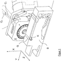
- FIG. 1 shows in the foreground a monolithic structure B, which extends inter alia in a width direction Z and is interspersed in this direction by a plurality of unspecified recesses.
- an approximately cylindrical processing head K is provided from the back of the Monoblockes B inserted into one of the recesses and extends through this completely.
- the processing head K extends in the Z direction and is held by a pivot drive V. This is able to pivot the machining head K about a freely definable angle of rotation about the Z-axis.
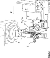
- the pivot drive V is common to the processing head K via an in Fig. 2 shown laser processing machine also movable in the Z direction, so that the processing head can take different Z positions within the Monoblockes B (with the laser processing machine, the machining head in the embodiment shown also in and around further translational or rotational degrees of freedom movable).
- the rotary actuator V is arranged on a carrier T via an unspecified holding device and can be moved over it, in particular in the Z direction.
- the holding device engages around an optical unit P, from which a laser beam L 'is directed as a raw beam into the rear end of the machining head K held by the pivoting drive V to be forwarded and deflected within the machining head K, as in FIG Fig. 3 is shown.
- the optical unit P is capable of aligning and focusing the laser beam L 'according to predefinable and rapidly variable parameters, so that it can irradiate at different X / Y positions into the processing head K or onto the deflection means. This is done for the purpose of screening in which different target points can be reached by the laser without relative movement of the machining head K to the monoblock B.
- On the side facing the optical unit P side of the pivot drive V see in particular Fig. 1 ) two closely spaced flow channels C 1 , C 2 are shown.
- the channel C 1 leads from a suction device, not shown, to a suction provided in the processing head K, while the port C 2 from a compressed air source also not shown pressure-tight in a central shaft S of the processing head K opens, in which also emitted by the optical unit P. Be directed laser beams L '.
- the supplied compressed air serves to protect the deflection means in order to keep them free of deposits, for example by means of an air cushion, which arise during laser processing. Further details are the 3 and 4 refer to.
- the monoblock B to be processed is surrounded by a frame F and is shown in a vertical, operative orientation so that the Z-direction extends horizontally.
- a load cross E is used to initiate a weight force in the monobloc.
- the emitted from the optical unit P raw beam L ' reaches in the horizontal direction the also horizontally oriented processing head K, which in turn is inserted in the horizontal Z-direction in the monoblock B.
- Such an arrangement advantageously allows a laser processing under the targeted application of force to the monobloc to generate force-dependent measured values, which in real time draw conclusions about the required post-processing, in particular at joint locations G (see FIG. Fig. 5 ) within the monoblock and allow the corresponding (post) processing in real time immediately.
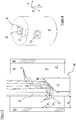
- FIG. 3 shows a simplified schematic sectional view of the machining head K according to the invention, which is formed substantially cylindrical about an axis extending in a first direction Z axis. It is inserted into a recess A of the monolithic structure B, which is illustrated only in simplified form, in order to machine a group of target points P 1 , P 2 ... By means of a laser within the structure B.
- a laser beam L is guided approximately along the direction Z through a central region (shaft S) of the machining head K in order to be deflected laterally in the X direction in the front end region of the head K in order to reach the target points.
- laser beam L 'K deflecting means U are provided in the front end region of the head.
- the embodiment shown is essentially a glass body with a mirror surface R which is inclined by approximately 45 ° with respect to the longitudinal direction Z.
- a laser beam L incident on the mirror surface R at a specific angle of incidence is reflected by the surface R with a corresponding angle of reflection.
- An approximately parallel to the Z-direction incident beam is therefore deflected at this mirror surface R approximately at right angles to the Z-axis, where it emerges through an exit opening O from the processing head K.
- FIG. 3 a plurality of incident or deflected laser beams L 'and L are shown. This is intended to indicate that the introduced into the processing head K laser beam L 'may be directed to different areas of the mirror surface R, whereby the correspondingly reflected laser beam L at different height or width positions of the outlet opening O emerges from this.
- This process is referred to as "rastering", in which the laser beam L 'is also directed in rapid succession to different regions of the mirror surface R and exclusively to different target points P 1 , P 2 .
- the deflection means U and the processing head K carrying them must not be moved relative to the monolithic structure B (pivoted about Z or moved in the Z direction).
- the machining head according to the invention can be moved in the Z direction and / or pivoted about its axis running in the Z direction. In this way, all target points lying laterally to the machining head within the recess A can be achieved or processed.
- a distance X K between the outer wall of the machining head K and the inner wall of the recess A or to the target points P 1 , P 2 is shown disproportionately large.
- the distance X K should be as low as possible in order to be able to discharge material removal directly into the suction channel C through the outlet opening O during the laser processing of the target points P 1 , P 2 ,.
- the deflected laser beams L end up in a peak which represents the highest energy density of the laser and thus the X position in which the target points should actually lie during processing.
- the outer diameter of the machining head K is therefore only insignificantly below the inner diameter of the recess A.
- the deflecting means U designed as bevelled glass cylinders are pushed and fixed over the front end of the machining head K to a suitable stop.
- the deflection can permanently or permanently with the machining head K connected, for example by gluing. Alternatively, however, a releasable attachment is conceivable to easily exchange the deflection U.
- a suction channel C guided through the machining head K opens into the outlet opening O in the region of the laser exit. Removal of material arising during the laser treatment can be conducted upwards through the suction head C through the machining head K.
- the mouth position of the suction channel C in the outlet opening O is chosen so that the removal of material does not reach the mirror surface R when sucking, but already as close to the exit point of the laser is sucked into the suction channel C.
- compressed air can also be fed in via the inlet channel S of the laser L '(by means of channel C 2 in accordance with FIG Fig. 2 ), which flows over the deflecting means and thereby keeps free from sucked through the opening O foreign bodies or material removal.
- the compressed air is further deflected in the direction X to the outlet opening O and there flows into the suction channel C, which additionally contributes to direct sucked from the outside material removal in the channel C.
- the suction channel C can, unlike in Fig. 1 represented, in the region of the outlet opening O also annular channel formed around the central axis of the machining head K, in order to achieve an improved suction.
- the individual recesses in the processing head can be manufactured with great design freedom.
- the laser channel, outlet opening O, recess for the deflection means U, suction channel C can be manufactured with great design freedom.
- the laser channel, through which the laser beam L 'is guided before impinging on the mirror surface R get a slightly conical shape.
- the supply air supplied by means of channel C 2 can be directed more precisely onto the deflection means.
- Fig. 4 shows the machining head perpendicular to the Z-axis slightly above the outlet opening O cut.
- On view is the centric, with rounded corners square executed laser inlet channel S, hit by the differently oriented laser beams L 'on the deflection means U, thereby laterally from the outlet opening O. to be led out. Compressed air also flows in the direction of the deflecting means through the laser inlet channel S. Above the outlet opening O, the approximately channel-shaped suction channel C can be seen.
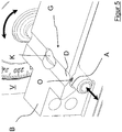
- FIG. 5 shows in an enlarged view a in the region of a hinge structure G in a monoblock B inserted machining head K, which is held by the pivot drive V.
- the machining head K has a length in the Z direction which exceeds the width of the monobloc B.
- the outlet opening O of the machining head K can be moved by method in the Z direction or pivoting about the Z axis (see arrows) to different positions within the block B to produce the thin spot D with the laser beams deflected out of the outlet opening O or to to edit. You can see it in Fig. 5 Furthermore, that the outer diameter of the machining head K is best adapted to the circular section geometry of the inner Dünnstellenausnaturalung A in order to dissipate material removal particularly well.
Landscapes
- Physics & Mathematics (AREA)
- Optics & Photonics (AREA)
- Engineering & Computer Science (AREA)
- Plasma & Fusion (AREA)
- Mechanical Engineering (AREA)
- Laser Beam Processing (AREA)
Applications Claiming Priority (1)
| Application Number | Priority Date | Filing Date | Title |
|---|---|---|---|
| DE102016105985.4A DE102016105985A1 (de) | 2016-04-01 | 2016-04-01 | Verfahren und Vorrichtung zur Laserbearbeitung |
Publications (2)
| Publication Number | Publication Date |
|---|---|
| EP3228417A1 true EP3228417A1 (fr) | 2017-10-11 |
| EP3228417B1 EP3228417B1 (fr) | 2022-02-16 |
Family
ID=58413009
Family Applications (1)
| Application Number | Title | Priority Date | Filing Date |
|---|---|---|---|
| EP17162860.5A Active EP3228417B1 (fr) | 2016-04-01 | 2017-03-24 | Procédé et dispositif de traitement laser de structures monolithiques utilisées dans le domaine du pesage |
Country Status (3)
| Country | Link |
|---|---|
| EP (1) | EP3228417B1 (fr) |
| JP (1) | JP6932020B2 (fr) |
| DE (2) | DE102016105985A1 (fr) |
Cited By (2)
| Publication number | Priority date | Publication date | Assignee | Title |
|---|---|---|---|---|
| IT201900024262A1 (it) * | 2019-12-17 | 2021-06-17 | Graf Synergy Srl | Stazione di taglio per profilati, particolarmente per serramenti |
| WO2021159158A1 (fr) * | 2020-02-12 | 2021-08-19 | Trotec Laser Gmbh | Traceur laser et procédé pour faire fonctionner un traceur laser |
Families Citing this family (6)
| Publication number | Priority date | Publication date | Assignee | Title |
|---|---|---|---|---|
| DE102016110151A1 (de) | 2016-06-01 | 2017-12-07 | Wipotec Wiege- Und Positioniersysteme Gmbh | Dünnstellengelenk |
| DE102016110152A1 (de) | 2016-06-01 | 2017-12-07 | Wipotec Wiege- Und Positioniersysteme Gmbh | Dünnstellengelenk |
| EP4253396A4 (fr) | 2020-11-27 | 2024-09-11 | Mirailab Bioscience Inc. | Mononucléotide beta-nicotinamide de grande pureté (nmn) et son procédé de production |
| CN113798689B (zh) * | 2021-10-22 | 2024-11-22 | 中山火炬职业技术学院 | 一种辅助光电激光发射器垂直于产品倾斜面的打标装置 |
| JPWO2024095807A1 (fr) | 2022-11-01 | 2024-05-10 | ||
| CN116748564B (zh) * | 2023-07-13 | 2024-05-14 | 大冶华晨铝业科技有限公司 | 一种多轨道铝型材坡口切割装置 |
Citations (7)
| Publication number | Priority date | Publication date | Assignee | Title |
|---|---|---|---|---|
| DE10118291A1 (de) * | 2001-04-12 | 2002-10-24 | Elotherm Gmbh | Vorrichtung zum Laser-Belichten einer Fläche von metalischen Werkstücken und deren Verwendung |
| DE102005019757A1 (de) * | 2005-04-28 | 2006-11-02 | Sms Elotherm Gmbh | Vorrichtung und Verfahren zum Behandeln von Flächen metallischer Bauelemente mittels Laserstrahls |
| DE102008015403A1 (de) * | 2008-03-22 | 2009-09-24 | Daimler Ag | Einrichtung zum Feinbearbeiten einer Innenoberfläche einer Werkstückbohrung |
| US20130153554A1 (en) * | 2010-05-25 | 2013-06-20 | Rofin-Lasag Ag | Fibre optic laser machining equipment for etching grooves forming incipient cracks |
| WO2013117754A1 (fr) * | 2012-02-10 | 2013-08-15 | Limo Patentverwaltung Gmbh & Co. Kg | Dispositif d'usinage au laser d'une surface d'une pièce, ou de traitement ultérieur d'un revêtement sur la face extérieure ou la face intérieure d'une pièce |
| DE102013108097A1 (de) | 2013-07-29 | 2015-01-29 | Sartorius Lab Instruments Gmbh & Co. Kg | Verfahren zur Fertigung eines Kraftmesskörpers |
| DE102013103791B4 (de) | 2013-04-16 | 2015-07-09 | Sartorius Lab Instruments Gmbh & Co. Kg | Monolithisches Wägesystem |
Family Cites Families (1)
| Publication number | Priority date | Publication date | Assignee | Title |
|---|---|---|---|---|
| DE112004002731D2 (de) * | 2003-12-04 | 2006-11-16 | Lbc Laserbearbeitungsct Gmbh | Vorrichtung zur Oberflächenbearbeitung einer Zylinderinnenfläche mit einem Laserstrahl |
-
2016
- 2016-04-01 DE DE102016105985.4A patent/DE102016105985A1/de active Pending
-
2017
- 2017-03-24 EP EP17162860.5A patent/EP3228417B1/fr active Active
- 2017-03-24 DE DE202017007345.5U patent/DE202017007345U1/de active Active
- 2017-03-31 JP JP2017071464A patent/JP6932020B2/ja active Active
Patent Citations (7)
| Publication number | Priority date | Publication date | Assignee | Title |
|---|---|---|---|---|
| DE10118291A1 (de) * | 2001-04-12 | 2002-10-24 | Elotherm Gmbh | Vorrichtung zum Laser-Belichten einer Fläche von metalischen Werkstücken und deren Verwendung |
| DE102005019757A1 (de) * | 2005-04-28 | 2006-11-02 | Sms Elotherm Gmbh | Vorrichtung und Verfahren zum Behandeln von Flächen metallischer Bauelemente mittels Laserstrahls |
| DE102008015403A1 (de) * | 2008-03-22 | 2009-09-24 | Daimler Ag | Einrichtung zum Feinbearbeiten einer Innenoberfläche einer Werkstückbohrung |
| US20130153554A1 (en) * | 2010-05-25 | 2013-06-20 | Rofin-Lasag Ag | Fibre optic laser machining equipment for etching grooves forming incipient cracks |
| WO2013117754A1 (fr) * | 2012-02-10 | 2013-08-15 | Limo Patentverwaltung Gmbh & Co. Kg | Dispositif d'usinage au laser d'une surface d'une pièce, ou de traitement ultérieur d'un revêtement sur la face extérieure ou la face intérieure d'une pièce |
| DE102013103791B4 (de) | 2013-04-16 | 2015-07-09 | Sartorius Lab Instruments Gmbh & Co. Kg | Monolithisches Wägesystem |
| DE102013108097A1 (de) | 2013-07-29 | 2015-01-29 | Sartorius Lab Instruments Gmbh & Co. Kg | Verfahren zur Fertigung eines Kraftmesskörpers |
Cited By (3)
| Publication number | Priority date | Publication date | Assignee | Title |
|---|---|---|---|---|
| IT201900024262A1 (it) * | 2019-12-17 | 2021-06-17 | Graf Synergy Srl | Stazione di taglio per profilati, particolarmente per serramenti |
| WO2021124070A1 (fr) * | 2019-12-17 | 2021-06-24 | Graf Synergy S.R.L. | Poste de coupe d'éléments profilés, en particulier de cadres de fenêtre et de porte, doté d'un ensemble de marquage au laser |
| WO2021159158A1 (fr) * | 2020-02-12 | 2021-08-19 | Trotec Laser Gmbh | Traceur laser et procédé pour faire fonctionner un traceur laser |
Also Published As
| Publication number | Publication date |
|---|---|
| JP6932020B2 (ja) | 2021-09-08 |
| DE202017007345U1 (de) | 2020-11-10 |
| EP3228417B1 (fr) | 2022-02-16 |
| DE102016105985A1 (de) | 2017-10-05 |
| JP2017185549A (ja) | 2017-10-12 |
Similar Documents
| Publication | Publication Date | Title |
|---|---|---|
| EP3228417B1 (fr) | Procédé et dispositif de traitement laser de structures monolithiques utilisées dans le domaine du pesage | |
| EP2310163B1 (fr) | Procédé d'orientation excentrée d'un faisceau laser par rapport à un axe de buse et de découpage oblique, tête d'usinage laser et machine d'usinage laser correspondantes | |
| EP0407969B1 (fr) | Procédé et dispositif pour réaliser des espaces creux dans les pièces à usiner au moyen d'un faisceau laser | |
| DE102010018686B4 (de) | Vorrichtung und Verfahren zum Laser-Auftragschweißen mit pulverförmigem Zusatzwerkstoff | |
| EP3678811B1 (fr) | Module optique interchangeable pour machine-outil laser | |
| EP1733837B1 (fr) | Dispositif pour séparer une pièce plane en matériau fragile par laser | |
| DE102015007142A1 (de) | Messvorrichtung für ein Laserbearbeitungssystem und Verfahren zum Durchführen von Positionsmessungen mittels eines Messstrahls auf einem Werkstück | |
| DE102011000005A1 (de) | Vorrichtung und Verfahren zur Bearbeitung eines Werkstücks mit einem Laserstrahl | |
| DE102018202203B4 (de) | Anordnung zur Justierung einer Pulverströmung in Bezug zur mittleren Längsachse eines Energiestrahls | |
| WO2019048608A1 (fr) | Module optique muni d'un dispositif permettant de changer automatiquement une optique de collimation | |
| DE102012003202A1 (de) | Vorrichtung und Verfahren zum Bearbeiten von Werkstücken, insbesondere von Schneiden oder mit Schneiden versehenen Werkstücken, mit einem Nasslaser | |
| WO2019048612A1 (fr) | Buse à poudre pour machine-outil laser | |
| DE202008017745U1 (de) | Vorrichtung zum Führen eines Lichtstrahls | |
| DE102008022210B4 (de) | Arbeitskopf und Laserbearbeitungsmaschine | |
| EP1238746A2 (fr) | Méthode et appareil de découpe et soudage laser à commande robotique | |
| DE202007012687U1 (de) | Laserschweißvorrichtung | |
| WO2019149872A1 (fr) | Dispositif d'usinage de matériau laser comprenant une unité de détection comportant une optique de relais | |
| DE3801068A1 (de) | Verfahren und vorrichtung zum abtragen mittels gebuendelter energiestrahlen | |
| EP3565687B1 (fr) | Outil laser comprenant une unité de réglage du point de focalisation | |
| DE102010020732B4 (de) | Vorrichtung und Verfahren zum Ausrichten eines Laserkopfes sowie Multi-Laserblock für eine Produktionsanlage | |
| DE10215446B4 (de) | Kombinierter Laserkopf für verschiedene Laserbearbeitungen | |
| DE10162379B4 (de) | Verfahren zum Herstellen einer Mikrobohrung | |
| WO2021052814A1 (fr) | Dispositif d'alimentation en matière | |
| DE102016010508A1 (de) | Vorrichtung, Bearbeitungsvorrichtung und Verfahren zum Durchführen eines Bearbeitungsprozesses mittels eines hochenergetischen Bearbeitungsstrahls unter Anpassung des Bearbeitstrahls nach Maßgabe einer aktuellen Bearbeitungssituation | |
| WO2019048611A1 (fr) | Module de focalisation interchangeable |
Legal Events
| Date | Code | Title | Description |
|---|---|---|---|
| REG | Reference to a national code |
Ref country code: DE Ref legal event code: R138 Ref document number: 202017007345 Country of ref document: DE Free format text: GERMAN DOCUMENT NUMBER IS 502017012590 |
|
| PUAI | Public reference made under article 153(3) epc to a published international application that has entered the european phase |
Free format text: ORIGINAL CODE: 0009012 |
|
| STAA | Information on the status of an ep patent application or granted ep patent |
Free format text: STATUS: THE APPLICATION HAS BEEN PUBLISHED |
|
| AK | Designated contracting states |
Kind code of ref document: A1 Designated state(s): AL AT BE BG CH CY CZ DE DK EE ES FI FR GB GR HR HU IE IS IT LI LT LU LV MC MK MT NL NO PL PT RO RS SE SI SK SM TR |
|
| AX | Request for extension of the european patent |
Extension state: BA ME |
|
| STAA | Information on the status of an ep patent application or granted ep patent |
Free format text: STATUS: REQUEST FOR EXAMINATION WAS MADE |
|
| 17P | Request for examination filed |
Effective date: 20180411 |
|
| RBV | Designated contracting states (corrected) |
Designated state(s): AL AT BE BG CH CY CZ DE DK EE ES FI FR GB GR HR HU IE IS IT LI LT LU LV MC MK MT NL NO PL PT RO RS SE SI SK SM TR |
|
| STAA | Information on the status of an ep patent application or granted ep patent |
Free format text: STATUS: EXAMINATION IS IN PROGRESS |
|
| 17Q | First examination report despatched |
Effective date: 20180918 |
|
| RIC1 | Information provided on ipc code assigned before grant |
Ipc: B23K 101/28 20060101ALN20210706BHEP Ipc: B23K 101/20 20060101ALN20210706BHEP Ipc: G01G 23/36 20060101ALI20210706BHEP Ipc: G01G 7/02 20060101ALI20210706BHEP Ipc: B23K 26/40 20140101ALI20210706BHEP Ipc: B23K 26/362 20140101ALI20210706BHEP Ipc: B23K 26/10 20060101ALI20210706BHEP Ipc: B23K 26/08 20140101AFI20210706BHEP |
|
| GRAP | Despatch of communication of intention to grant a patent |
Free format text: ORIGINAL CODE: EPIDOSNIGR1 |
|
| STAA | Information on the status of an ep patent application or granted ep patent |
Free format text: STATUS: GRANT OF PATENT IS INTENDED |
|
| RIC1 | Information provided on ipc code assigned before grant |
Ipc: B23K 101/28 20060101ALN20210823BHEP Ipc: B23K 101/20 20060101ALN20210823BHEP Ipc: G01G 23/36 20060101ALI20210823BHEP Ipc: G01G 7/02 20060101ALI20210823BHEP Ipc: B23K 26/40 20140101ALI20210823BHEP Ipc: B23K 26/362 20140101ALI20210823BHEP Ipc: B23K 26/10 20060101ALI20210823BHEP Ipc: B23K 26/08 20140101AFI20210823BHEP |
|
| INTG | Intention to grant announced |
Effective date: 20210907 |
|
| RIC1 | Information provided on ipc code assigned before grant |
Ipc: B23K 101/28 20060101ALN20210830BHEP Ipc: B23K 101/20 20060101ALN20210830BHEP Ipc: G01G 23/36 20060101ALI20210830BHEP Ipc: G01G 7/02 20060101ALI20210830BHEP Ipc: B23K 26/40 20140101ALI20210830BHEP Ipc: B23K 26/362 20140101ALI20210830BHEP Ipc: B23K 26/10 20060101ALI20210830BHEP Ipc: B23K 26/08 20140101AFI20210830BHEP |
|
| GRAS | Grant fee paid |
Free format text: ORIGINAL CODE: EPIDOSNIGR3 |
|
| GRAA | (expected) grant |
Free format text: ORIGINAL CODE: 0009210 |
|
| STAA | Information on the status of an ep patent application or granted ep patent |
Free format text: STATUS: THE PATENT HAS BEEN GRANTED |
|
| AK | Designated contracting states |
Kind code of ref document: B1 Designated state(s): AL AT BE BG CH CY CZ DE DK EE ES FI FR GB GR HR HU IE IS IT LI LT LU LV MC MK MT NL NO PL PT RO RS SE SI SK SM TR |
|
| RAP3 | Party data changed (applicant data changed or rights of an application transferred) |
Owner name: WIPOTEC GMBH |
|
| REG | Reference to a national code |
Ref country code: GB Ref legal event code: FG4D Free format text: NOT ENGLISH |
|
| REG | Reference to a national code |
Ref country code: CH Ref legal event code: EP |
|
| REG | Reference to a national code |
Ref country code: DE Ref legal event code: R096 Ref document number: 502017012590 Country of ref document: DE |
|
| REG | Reference to a national code |
Ref country code: AT Ref legal event code: REF Ref document number: 1468586 Country of ref document: AT Kind code of ref document: T Effective date: 20220315 |
|
| REG | Reference to a national code |
Ref country code: IE Ref legal event code: FG4D Free format text: LANGUAGE OF EP DOCUMENT: GERMAN |
|
| REG | Reference to a national code |
Ref country code: LT Ref legal event code: MG9D |
|
| REG | Reference to a national code |
Ref country code: NL Ref legal event code: MP Effective date: 20220216 |
|
| PG25 | Lapsed in a contracting state [announced via postgrant information from national office to epo] |
Ref country code: SE Free format text: LAPSE BECAUSE OF FAILURE TO SUBMIT A TRANSLATION OF THE DESCRIPTION OR TO PAY THE FEE WITHIN THE PRESCRIBED TIME-LIMIT Effective date: 20220216 Ref country code: RS Free format text: LAPSE BECAUSE OF FAILURE TO SUBMIT A TRANSLATION OF THE DESCRIPTION OR TO PAY THE FEE WITHIN THE PRESCRIBED TIME-LIMIT Effective date: 20220216 Ref country code: PT Free format text: LAPSE BECAUSE OF FAILURE TO SUBMIT A TRANSLATION OF THE DESCRIPTION OR TO PAY THE FEE WITHIN THE PRESCRIBED TIME-LIMIT Effective date: 20220616 Ref country code: NO Free format text: LAPSE BECAUSE OF FAILURE TO SUBMIT A TRANSLATION OF THE DESCRIPTION OR TO PAY THE FEE WITHIN THE PRESCRIBED TIME-LIMIT Effective date: 20220516 Ref country code: NL Free format text: LAPSE BECAUSE OF FAILURE TO SUBMIT A TRANSLATION OF THE DESCRIPTION OR TO PAY THE FEE WITHIN THE PRESCRIBED TIME-LIMIT Effective date: 20220216 Ref country code: LT Free format text: LAPSE BECAUSE OF FAILURE TO SUBMIT A TRANSLATION OF THE DESCRIPTION OR TO PAY THE FEE WITHIN THE PRESCRIBED TIME-LIMIT Effective date: 20220216 Ref country code: HR Free format text: LAPSE BECAUSE OF FAILURE TO SUBMIT A TRANSLATION OF THE DESCRIPTION OR TO PAY THE FEE WITHIN THE PRESCRIBED TIME-LIMIT Effective date: 20220216 Ref country code: ES Free format text: LAPSE BECAUSE OF FAILURE TO SUBMIT A TRANSLATION OF THE DESCRIPTION OR TO PAY THE FEE WITHIN THE PRESCRIBED TIME-LIMIT Effective date: 20220216 Ref country code: BG Free format text: LAPSE BECAUSE OF FAILURE TO SUBMIT A TRANSLATION OF THE DESCRIPTION OR TO PAY THE FEE WITHIN THE PRESCRIBED TIME-LIMIT Effective date: 20220516 |
|
| PG25 | Lapsed in a contracting state [announced via postgrant information from national office to epo] |
Ref country code: PL Free format text: LAPSE BECAUSE OF FAILURE TO SUBMIT A TRANSLATION OF THE DESCRIPTION OR TO PAY THE FEE WITHIN THE PRESCRIBED TIME-LIMIT Effective date: 20220216 Ref country code: LV Free format text: LAPSE BECAUSE OF FAILURE TO SUBMIT A TRANSLATION OF THE DESCRIPTION OR TO PAY THE FEE WITHIN THE PRESCRIBED TIME-LIMIT Effective date: 20220216 Ref country code: GR Free format text: LAPSE BECAUSE OF FAILURE TO SUBMIT A TRANSLATION OF THE DESCRIPTION OR TO PAY THE FEE WITHIN THE PRESCRIBED TIME-LIMIT Effective date: 20220517 Ref country code: FI Free format text: LAPSE BECAUSE OF FAILURE TO SUBMIT A TRANSLATION OF THE DESCRIPTION OR TO PAY THE FEE WITHIN THE PRESCRIBED TIME-LIMIT Effective date: 20220216 |
|
| PG25 | Lapsed in a contracting state [announced via postgrant information from national office to epo] |
Ref country code: IS Free format text: LAPSE BECAUSE OF FAILURE TO SUBMIT A TRANSLATION OF THE DESCRIPTION OR TO PAY THE FEE WITHIN THE PRESCRIBED TIME-LIMIT Effective date: 20220617 |
|
| PG25 | Lapsed in a contracting state [announced via postgrant information from national office to epo] |
Ref country code: SM Free format text: LAPSE BECAUSE OF FAILURE TO SUBMIT A TRANSLATION OF THE DESCRIPTION OR TO PAY THE FEE WITHIN THE PRESCRIBED TIME-LIMIT Effective date: 20220216 Ref country code: SK Free format text: LAPSE BECAUSE OF FAILURE TO SUBMIT A TRANSLATION OF THE DESCRIPTION OR TO PAY THE FEE WITHIN THE PRESCRIBED TIME-LIMIT Effective date: 20220216 Ref country code: RO Free format text: LAPSE BECAUSE OF FAILURE TO SUBMIT A TRANSLATION OF THE DESCRIPTION OR TO PAY THE FEE WITHIN THE PRESCRIBED TIME-LIMIT Effective date: 20220216 Ref country code: EE Free format text: LAPSE BECAUSE OF FAILURE TO SUBMIT A TRANSLATION OF THE DESCRIPTION OR TO PAY THE FEE WITHIN THE PRESCRIBED TIME-LIMIT Effective date: 20220216 Ref country code: DK Free format text: LAPSE BECAUSE OF FAILURE TO SUBMIT A TRANSLATION OF THE DESCRIPTION OR TO PAY THE FEE WITHIN THE PRESCRIBED TIME-LIMIT Effective date: 20220216 Ref country code: CZ Free format text: LAPSE BECAUSE OF FAILURE TO SUBMIT A TRANSLATION OF THE DESCRIPTION OR TO PAY THE FEE WITHIN THE PRESCRIBED TIME-LIMIT Effective date: 20220216 |
|
| REG | Reference to a national code |
Ref country code: DE Ref legal event code: R097 Ref document number: 502017012590 Country of ref document: DE |
|
| PG25 | Lapsed in a contracting state [announced via postgrant information from national office to epo] |
Ref country code: MC Free format text: LAPSE BECAUSE OF FAILURE TO SUBMIT A TRANSLATION OF THE DESCRIPTION OR TO PAY THE FEE WITHIN THE PRESCRIBED TIME-LIMIT Effective date: 20220216 Ref country code: AL Free format text: LAPSE BECAUSE OF FAILURE TO SUBMIT A TRANSLATION OF THE DESCRIPTION OR TO PAY THE FEE WITHIN THE PRESCRIBED TIME-LIMIT Effective date: 20220216 |
|
| REG | Reference to a national code |
Ref country code: BE Ref legal event code: MM Effective date: 20220331 |
|
| PLBE | No opposition filed within time limit |
Free format text: ORIGINAL CODE: 0009261 |
|
| STAA | Information on the status of an ep patent application or granted ep patent |
Free format text: STATUS: NO OPPOSITION FILED WITHIN TIME LIMIT |
|
| 26N | No opposition filed |
Effective date: 20221117 |
|
| GBPC | Gb: european patent ceased through non-payment of renewal fee |
Effective date: 20220516 |
|
| PG25 | Lapsed in a contracting state [announced via postgrant information from national office to epo] |
Ref country code: LU Free format text: LAPSE BECAUSE OF NON-PAYMENT OF DUE FEES Effective date: 20220324 Ref country code: IE Free format text: LAPSE BECAUSE OF NON-PAYMENT OF DUE FEES Effective date: 20220324 Ref country code: FR Free format text: LAPSE BECAUSE OF NON-PAYMENT OF DUE FEES Effective date: 20220416 |
|
| PG25 | Lapsed in a contracting state [announced via postgrant information from national office to epo] |
Ref country code: SI Free format text: LAPSE BECAUSE OF FAILURE TO SUBMIT A TRANSLATION OF THE DESCRIPTION OR TO PAY THE FEE WITHIN THE PRESCRIBED TIME-LIMIT Effective date: 20220216 Ref country code: BE Free format text: LAPSE BECAUSE OF NON-PAYMENT OF DUE FEES Effective date: 20220331 |
|
| REG | Reference to a national code |
Ref country code: AT Ref legal event code: MM01 Ref document number: 1468586 Country of ref document: AT Kind code of ref document: T Effective date: 20220324 |
|
| PG25 | Lapsed in a contracting state [announced via postgrant information from national office to epo] |
Ref country code: GB Free format text: LAPSE BECAUSE OF NON-PAYMENT OF DUE FEES Effective date: 20220516 |
|
| PG25 | Lapsed in a contracting state [announced via postgrant information from national office to epo] |
Ref country code: IT Free format text: LAPSE BECAUSE OF FAILURE TO SUBMIT A TRANSLATION OF THE DESCRIPTION OR TO PAY THE FEE WITHIN THE PRESCRIBED TIME-LIMIT Effective date: 20220216 Ref country code: AT Free format text: LAPSE BECAUSE OF NON-PAYMENT OF DUE FEES Effective date: 20220324 |
|
| PG25 | Lapsed in a contracting state [announced via postgrant information from national office to epo] |
Ref country code: HU Free format text: LAPSE BECAUSE OF FAILURE TO SUBMIT A TRANSLATION OF THE DESCRIPTION OR TO PAY THE FEE WITHIN THE PRESCRIBED TIME-LIMIT; INVALID AB INITIO Effective date: 20170324 |
|
| PG25 | Lapsed in a contracting state [announced via postgrant information from national office to epo] |
Ref country code: MK Free format text: LAPSE BECAUSE OF FAILURE TO SUBMIT A TRANSLATION OF THE DESCRIPTION OR TO PAY THE FEE WITHIN THE PRESCRIBED TIME-LIMIT Effective date: 20220216 Ref country code: CY Free format text: LAPSE BECAUSE OF FAILURE TO SUBMIT A TRANSLATION OF THE DESCRIPTION OR TO PAY THE FEE WITHIN THE PRESCRIBED TIME-LIMIT Effective date: 20220216 |
|
| PG25 | Lapsed in a contracting state [announced via postgrant information from national office to epo] |
Ref country code: TR Free format text: LAPSE BECAUSE OF FAILURE TO SUBMIT A TRANSLATION OF THE DESCRIPTION OR TO PAY THE FEE WITHIN THE PRESCRIBED TIME-LIMIT Effective date: 20220216 |
|
| PG25 | Lapsed in a contracting state [announced via postgrant information from national office to epo] |
Ref country code: MT Free format text: LAPSE BECAUSE OF FAILURE TO SUBMIT A TRANSLATION OF THE DESCRIPTION OR TO PAY THE FEE WITHIN THE PRESCRIBED TIME-LIMIT Effective date: 20220216 |
|
| PGFP | Annual fee paid to national office [announced via postgrant information from national office to epo] |
Ref country code: CH Payment date: 20250401 Year of fee payment: 9 |
|
| REG | Reference to a national code |
Ref country code: CH Ref legal event code: U11 Free format text: ST27 STATUS EVENT CODE: U-0-0-U10-U11 (AS PROVIDED BY THE NATIONAL OFFICE) Effective date: 20260401 |
|
| PGFP | Annual fee paid to national office [announced via postgrant information from national office to epo] |
Ref country code: DE Payment date: 20260227 Year of fee payment: 10 |