EP3228491A1 - Moteur électrique pour machine mobile - Google Patents
Moteur électrique pour machine mobile Download PDFInfo
- Publication number
- EP3228491A1 EP3228491A1 EP17164467.7A EP17164467A EP3228491A1 EP 3228491 A1 EP3228491 A1 EP 3228491A1 EP 17164467 A EP17164467 A EP 17164467A EP 3228491 A1 EP3228491 A1 EP 3228491A1
- Authority
- EP
- European Patent Office
- Prior art keywords
- contact
- power electronics
- housing
- motor unit
- electric motor
- Prior art date
- Legal status (The legal status is an assumption and is not a legal conclusion. Google has not performed a legal analysis and makes no representation as to the accuracy of the status listed.)
- Granted
Links
Images

Classifications
-
- H—ELECTRICITY
- H02—GENERATION; CONVERSION OR DISTRIBUTION OF ELECTRIC POWER
- H02K—DYNAMO-ELECTRIC MACHINES
- H02K11/00—Structural association of dynamo-electric machines with electric components or with devices for shielding, monitoring or protection
- H02K11/30—Structural association with control circuits or drive circuits
- H02K11/33—Drive circuits, e.g. power electronics
-
- B—PERFORMING OPERATIONS; TRANSPORTING
- B60—VEHICLES IN GENERAL
- B60L—PROPULSION OF ELECTRICALLY-PROPELLED VEHICLES; SUPPLYING ELECTRIC POWER FOR AUXILIARY EQUIPMENT OF ELECTRICALLY-PROPELLED VEHICLES; ELECTRODYNAMIC BRAKE SYSTEMS FOR VEHICLES IN GENERAL; MAGNETIC SUSPENSION OR LEVITATION FOR VEHICLES; MONITORING OPERATING VARIABLES OF ELECTRICALLY-PROPELLED VEHICLES; ELECTRIC SAFETY DEVICES FOR ELECTRICALLY-PROPELLED VEHICLES
- B60L3/00—Electric devices on electrically-propelled vehicles for safety purposes; Monitoring operating variables, e.g. speed, deceleration or energy consumption
- B60L3/0023—Detecting, eliminating, remedying or compensating for drive train abnormalities, e.g. failures within the drive train
- B60L3/0069—Detecting, eliminating, remedying or compensating for drive train abnormalities, e.g. failures within the drive train relating to the isolation, e.g. ground fault or leak current
-
- B—PERFORMING OPERATIONS; TRANSPORTING
- B60—VEHICLES IN GENERAL
- B60L—PROPULSION OF ELECTRICALLY-PROPELLED VEHICLES; SUPPLYING ELECTRIC POWER FOR AUXILIARY EQUIPMENT OF ELECTRICALLY-PROPELLED VEHICLES; ELECTRODYNAMIC BRAKE SYSTEMS FOR VEHICLES IN GENERAL; MAGNETIC SUSPENSION OR LEVITATION FOR VEHICLES; MONITORING OPERATING VARIABLES OF ELECTRICALLY-PROPELLED VEHICLES; ELECTRIC SAFETY DEVICES FOR ELECTRICALLY-PROPELLED VEHICLES
- B60L50/00—Electric propulsion with power supplied within the vehicle
- B60L50/10—Electric propulsion with power supplied within the vehicle using propulsion power supplied by engine-driven generators, e.g. generators driven by combustion engines
- B60L50/13—Electric propulsion with power supplied within the vehicle using propulsion power supplied by engine-driven generators, e.g. generators driven by combustion engines using AC generators and AC motors
-
- B—PERFORMING OPERATIONS; TRANSPORTING
- B60—VEHICLES IN GENERAL
- B60L—PROPULSION OF ELECTRICALLY-PROPELLED VEHICLES; SUPPLYING ELECTRIC POWER FOR AUXILIARY EQUIPMENT OF ELECTRICALLY-PROPELLED VEHICLES; ELECTRODYNAMIC BRAKE SYSTEMS FOR VEHICLES IN GENERAL; MAGNETIC SUSPENSION OR LEVITATION FOR VEHICLES; MONITORING OPERATING VARIABLES OF ELECTRICALLY-PROPELLED VEHICLES; ELECTRIC SAFETY DEVICES FOR ELECTRICALLY-PROPELLED VEHICLES
- B60L50/00—Electric propulsion with power supplied within the vehicle
- B60L50/50—Electric propulsion with power supplied within the vehicle using propulsion power supplied by batteries or fuel cells
- B60L50/51—Electric propulsion with power supplied within the vehicle using propulsion power supplied by batteries or fuel cells characterised by AC-motors
-
- H—ELECTRICITY
- H02—GENERATION; CONVERSION OR DISTRIBUTION OF ELECTRIC POWER
- H02K—DYNAMO-ELECTRIC MACHINES
- H02K5/00—Casings; Enclosures; Supports
- H02K5/04—Casings or enclosures characterised by the shape, form or construction thereof
- H02K5/18—Casings or enclosures characterised by the shape, form or construction thereof with ribs or fins for improving heat transfer
-
- H—ELECTRICITY
- H02—GENERATION; CONVERSION OR DISTRIBUTION OF ELECTRIC POWER
- H02K—DYNAMO-ELECTRIC MACHINES
- H02K5/00—Casings; Enclosures; Supports
- H02K5/04—Casings or enclosures characterised by the shape, form or construction thereof
- H02K5/22—Auxiliary parts of casings not covered by groups H02K5/06-H02K5/20, e.g. shaped to form connection boxes or terminal boxes
- H02K5/225—Terminal boxes or connection arrangements
-
- B—PERFORMING OPERATIONS; TRANSPORTING
- B60—VEHICLES IN GENERAL
- B60L—PROPULSION OF ELECTRICALLY-PROPELLED VEHICLES; SUPPLYING ELECTRIC POWER FOR AUXILIARY EQUIPMENT OF ELECTRICALLY-PROPELLED VEHICLES; ELECTRODYNAMIC BRAKE SYSTEMS FOR VEHICLES IN GENERAL; MAGNETIC SUSPENSION OR LEVITATION FOR VEHICLES; MONITORING OPERATING VARIABLES OF ELECTRICALLY-PROPELLED VEHICLES; ELECTRIC SAFETY DEVICES FOR ELECTRICALLY-PROPELLED VEHICLES
- B60L2200/00—Type of vehicles
- B60L2200/40—Working vehicles
- B60L2200/42—Fork lift trucks
-
- B—PERFORMING OPERATIONS; TRANSPORTING
- B60—VEHICLES IN GENERAL
- B60L—PROPULSION OF ELECTRICALLY-PROPELLED VEHICLES; SUPPLYING ELECTRIC POWER FOR AUXILIARY EQUIPMENT OF ELECTRICALLY-PROPELLED VEHICLES; ELECTRODYNAMIC BRAKE SYSTEMS FOR VEHICLES IN GENERAL; MAGNETIC SUSPENSION OR LEVITATION FOR VEHICLES; MONITORING OPERATING VARIABLES OF ELECTRICALLY-PROPELLED VEHICLES; ELECTRIC SAFETY DEVICES FOR ELECTRICALLY-PROPELLED VEHICLES
- B60L2200/00—Type of vehicles
- B60L2200/40—Working vehicles
- B60L2200/44—Industrial trucks or floor conveyors
-
- B—PERFORMING OPERATIONS; TRANSPORTING
- B60—VEHICLES IN GENERAL
- B60L—PROPULSION OF ELECTRICALLY-PROPELLED VEHICLES; SUPPLYING ELECTRIC POWER FOR AUXILIARY EQUIPMENT OF ELECTRICALLY-PROPELLED VEHICLES; ELECTRODYNAMIC BRAKE SYSTEMS FOR VEHICLES IN GENERAL; MAGNETIC SUSPENSION OR LEVITATION FOR VEHICLES; MONITORING OPERATING VARIABLES OF ELECTRICALLY-PROPELLED VEHICLES; ELECTRIC SAFETY DEVICES FOR ELECTRICALLY-PROPELLED VEHICLES
- B60L2270/00—Problem solutions or means not otherwise provided for
- B60L2270/10—Emission reduction
- B60L2270/14—Emission reduction of noise
- B60L2270/147—Emission reduction of noise electro magnetic [EMI]
-
- Y—GENERAL TAGGING OF NEW TECHNOLOGICAL DEVELOPMENTS; GENERAL TAGGING OF CROSS-SECTIONAL TECHNOLOGIES SPANNING OVER SEVERAL SECTIONS OF THE IPC; TECHNICAL SUBJECTS COVERED BY FORMER USPC CROSS-REFERENCE ART COLLECTIONS [XRACs] AND DIGESTS
- Y02—TECHNOLOGIES OR APPLICATIONS FOR MITIGATION OR ADAPTATION AGAINST CLIMATE CHANGE
- Y02P—CLIMATE CHANGE MITIGATION TECHNOLOGIES IN THE PRODUCTION OR PROCESSING OF GOODS
- Y02P90/00—Enabling technologies with a potential contribution to greenhouse gas [GHG] emissions mitigation
- Y02P90/60—Electric or hybrid propulsion means for production processes
-
- Y—GENERAL TAGGING OF NEW TECHNOLOGICAL DEVELOPMENTS; GENERAL TAGGING OF CROSS-SECTIONAL TECHNOLOGIES SPANNING OVER SEVERAL SECTIONS OF THE IPC; TECHNICAL SUBJECTS COVERED BY FORMER USPC CROSS-REFERENCE ART COLLECTIONS [XRACs] AND DIGESTS
- Y02—TECHNOLOGIES OR APPLICATIONS FOR MITIGATION OR ADAPTATION AGAINST CLIMATE CHANGE
- Y02T—CLIMATE CHANGE MITIGATION TECHNOLOGIES RELATED TO TRANSPORTATION
- Y02T10/00—Road transport of goods or passengers
- Y02T10/60—Other road transportation technologies with climate change mitigation effect
- Y02T10/64—Electric machine technologies in electromobility
-
- Y—GENERAL TAGGING OF NEW TECHNOLOGICAL DEVELOPMENTS; GENERAL TAGGING OF CROSS-SECTIONAL TECHNOLOGIES SPANNING OVER SEVERAL SECTIONS OF THE IPC; TECHNICAL SUBJECTS COVERED BY FORMER USPC CROSS-REFERENCE ART COLLECTIONS [XRACs] AND DIGESTS
- Y02—TECHNOLOGIES OR APPLICATIONS FOR MITIGATION OR ADAPTATION AGAINST CLIMATE CHANGE
- Y02T—CLIMATE CHANGE MITIGATION TECHNOLOGIES RELATED TO TRANSPORTATION
- Y02T10/00—Road transport of goods or passengers
- Y02T10/60—Other road transportation technologies with climate change mitigation effect
- Y02T10/70—Energy storage systems for electromobility, e.g. batteries
-
- Y—GENERAL TAGGING OF NEW TECHNOLOGICAL DEVELOPMENTS; GENERAL TAGGING OF CROSS-SECTIONAL TECHNOLOGIES SPANNING OVER SEVERAL SECTIONS OF THE IPC; TECHNICAL SUBJECTS COVERED BY FORMER USPC CROSS-REFERENCE ART COLLECTIONS [XRACs] AND DIGESTS
- Y02—TECHNOLOGIES OR APPLICATIONS FOR MITIGATION OR ADAPTATION AGAINST CLIMATE CHANGE
- Y02T—CLIMATE CHANGE MITIGATION TECHNOLOGIES RELATED TO TRANSPORTATION
- Y02T10/00—Road transport of goods or passengers
- Y02T10/60—Other road transportation technologies with climate change mitigation effect
- Y02T10/7072—Electromobility specific charging systems or methods for batteries, ultracapacitors, supercapacitors or double-layer capacitors
Definitions
- the invention relates to an electric motor unit for a mobile work machine.
- the invention relates to an electric drive axle for a mobile work machine having at least one electric drive motor, a power electronics for driving the drive motor, which is arranged in a power electronics housing, wherein the power electronics housing is connected to a motor housing via a parting line and pressure contacts of power terminals of the power electronics and the drive motor in the connecting region of the power electronics housing and the motor housing are arranged in the interior of the housing and cooperate to form an electrical connection, of which in each case a pressure contact as power electronics contact of the power electronics and associated with this pressure contact is assigned as a terminal contact the drive motor.
- electric traction drives In mobile machines especially forklifts, such as counterbalanced forklifts, reach trucks and warehouse equipment, electric traction drives are known in which electric motors are arranged in an axle housing. Such traction drives are known both in diesel-electric powered mobile machines in which is powered by an internal combustion engine and a generator, the electric traction drive with energy, as well as to a very large extent in battery-powered electric mobile machines and trucks.
- the electric motors are usually three-phase motors, which are controlled by a power electronics, in particular a converter. It is known to arrange the inverter separately from the electric motor or the axle in the vehicle, for example in a counterbalance forklift on the counterweight to dissipate the waste heat on the counterweight.
- the power electronics and the axle are often thermally decoupled by baffles so that there is no direct thermal coupling between the electric motors of the axle and the power electronics or the inverter.
- motor units that consist of a converter combined with an electric motor.
- Such motor units are used, for example, to form a hydraulic pump drive when connected to a hydraulic pump for work hydraulics.
- motor units are used as electrical steering drive in a steer-by-wire steering of a truck.
- each pressure contact has a arranged on the power electronics unit and arranged on the axis of contact surface, wherein at least one contact surface is spring-loaded in the direction of the other contact surface.
- a disadvantage of this prior art is that even with spring-loaded contacts due to unevenness, oxidation or contamination of the contact surfaces, it can lead to a poor connection.
- the present invention is therefore an object of the invention to provide an electric drive axle for a mobile machine available, which avoids the aforementioned disadvantages and with a montage friendly, compact and safe electrical connection of a power electronics to the traction motors can be achieved.
- an electric motor unit for a mobile machine with at least one electric drive motor a specific power electronics for driving the drive motor, which is arranged in a power electronics housing, wherein the power electronics housing is connected to a motor housing via a parting line and pressure contacts are arranged in the interior of the housing of power terminals of the power electronics and the drive motor in the connection region of power electronics housing and motor housing and cooperate to form an electrical connection, each of which a pressure contact as power electronics contact the power electronics and a cooperating with this pressure contact is assigned as a terminal contact the drive motor, at least one the pressure contacts in the direction of its interacting with this pressure contact with a spring force and applied via egg ne minimum distance is arranged to be movable and a pressure contact is a line contact and the cooperating with this pressure contact is a surface contact.
- connection of the arranged in the interior of the two housing in the connection area and aligned pressure contacts can be arranged so and the connection of the housing to the parting line be designed so that no incorrect installation is possible and with a correct installation always the right connections are made automatically. For example, this can be done by designing a flange as a parting line and / or the arrangement of screw.
- the spring load and the line contact or point contact creates a secure electrical connection, regardless of unevenness, dirt or oxidation.
- the surface pressure on the line contact line is uniformly high over a wide range of compression of a spring. By the spring travel of the spring load can also Inaccuracies and tolerances are compensated.
- a line contact can be generated for example by a sharp edge or edge.
- the point contact may refer to multiple points or a single and may be achieved by one or more peaks of the pressure contact.
- the entire electrical connections are located inside the housing formed by the power electronics housing and motor housing. This results in a great robustness, a small volume and a protected arrangement of the electrical connection between power electronics and electric drive motor with respect to moisture and dirt. As external power wiring with cables, busbars, etc. is eliminated, fewer components result and the protected design can additionally increase the protection class of the drive without the need for additional measures. There are cost advantages and a simpler, faster installation is possible.
- the efficiency and performance is increased due to the smaller construction volume and resulting lower electromagnetic radiation. It is a higher-frequency switching of the power electronics possible, for example as a converter.
- the application of a spring force can be effected by any conceivable form of springs and elastically deformable materials.
- the surface contact can be acted upon by a spring force.
- the surface contact consists of a cable lug, which is guided by a guide pin, wherein a spiral spring is arranged around the guide pin, which presses on the cable lug.
- the line contact may consist of a sleeve whose leading edge forms a cutting edge.
- the flat eye of a lug for example, guided by the guide pin from the bottom with a set around the guide mandrel coil spring with spring force, while from above a pressure contact on this as Line contact presses, for example, a cylindrical sleeve with a cutting edge at a front end.
- the point contact may consist of a sleeve whose leading edge has a structure forming one or more punctiform protrusions.
- the sleeve may be aligned coaxially with the guide pin.
- the power electronics housing faces at least a portion of a surface of the motor housing which is shaped as a heat sink.
- the power electronics housing projects laterally beyond the connection region or the region of the parting line and faces a surface toward the motor housing, this surface having fins of a heat sink, a channel is thereby formed between the motor housing and the power electronics housing, through which cooling air can be conducted efficiently.
- the power electronics contact may be line contact or point contact.
- connection contact can be acted upon by the spring force.
- the mobile machine is an industrial truck.
- the motor unit may be a drive axle of the work machine, or a hydraulic pump drive, or an electric steering drive.
- the Fig. 1 shows a detail of a drive axle 1 as an example of a motor unit in section with the solution according to the invention.
- An axle housing or motor housing 2 abuts a parting line 3 to a power electronics housing 4.
- an electric drive motor 5 of which in the illustration only a part of the windings is indicated, via a cable 6 with a cable lug 7 as a terminal contact 8 is connected in the form of a pressure contact 9.
- the cable lug 7 is guided on a guide pin 10 and is pressed by a coil spring 11 in the illustration up or acted upon by a spring force.
- a sleeve 12 which is constructed as a hollow cylinder and is aligned coaxially with the guide pin 10 has at its front end a cutting edge 13 and is pressed as power electronics contact 14 in the form of a pressure contact 9 on the cable lug 7 when the power electronics housing 4 at the parting line 3 is connected to the motor housing 2 and mounted on this. Due to the force of the coil spring 11 of the flat cable lug 7 against the cutting edge 13 of the sleeve 12th pressed, which forms a line contact. Via a power rail 15 of the power electronics contact 14 with a power electronics, not shown here, for example, a converter connected.
- connection of the pressure contacts 9 or of the power electronics contact 14 to the connection contact 8 takes place automatically, with six connections due to the positioning of the three connections typically required for a three-phase connection, or six connections in the case of a right and left drive motor is excluded if the power electronics housing 4 can be mounted only in one way and is mounted correctly.
- the power electronics housing 4 has a portion of a surface 16 formed as a heat sink, which faces a surface 17 of the motor housing 2 with cooling fins 18. Between the surface 16 and the surface 17, a channel is formed, can be passed through the cooling air to cool both a power electronics as well as the electric drive motor 5.
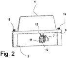
- the Fig. 2 schematically shows an electrical connection with power electronics housing 4 and axle housing 2, which are connected to the parting line 3 with a screw 19.
- the sleeve 12 forms a line contact with the cable lug 7.
- the cable lug 7, guided by the guide pin 10, is pressed by the coil spring 11 against the sleeve 12.
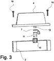
- the Fig. 3 shows the components of the Fig. 2 as an exploded view with power electronics housing 4, motor housing 2, screw 19, sleeve 12, cable lug 7, guide pin 10 and coil spring 11th
Landscapes
- Engineering & Computer Science (AREA)
- Power Engineering (AREA)
- Transportation (AREA)
- Mechanical Engineering (AREA)
- Life Sciences & Earth Sciences (AREA)
- Sustainable Development (AREA)
- Sustainable Energy (AREA)
- Microelectronics & Electronic Packaging (AREA)
- Physics & Mathematics (AREA)
- Thermal Sciences (AREA)
- Motor Or Generator Frames (AREA)
- Connection Of Motors, Electrical Generators, Mechanical Devices, And The Like (AREA)
Applications Claiming Priority (1)
| Application Number | Priority Date | Filing Date | Title |
|---|---|---|---|
| DE102016106104.2A DE102016106104A1 (de) | 2016-04-04 | 2016-04-04 | Elektrische Motoreinheit für mobile Arbeitsmaschine |
Publications (3)
| Publication Number | Publication Date |
|---|---|
| EP3228491A1 true EP3228491A1 (fr) | 2017-10-11 |
| EP3228491B1 EP3228491B1 (fr) | 2018-11-21 |
| EP3228491B9 EP3228491B9 (fr) | 2019-03-06 |
Family
ID=58488875
Family Applications (1)
| Application Number | Title | Priority Date | Filing Date |
|---|---|---|---|
| EP17164467.7A Active EP3228491B9 (fr) | 2016-04-04 | 2017-04-03 | Moteur électrique pour machine mobile |
Country Status (2)
| Country | Link |
|---|---|
| EP (1) | EP3228491B9 (fr) |
| DE (1) | DE102016106104A1 (fr) |
Families Citing this family (2)
| Publication number | Priority date | Publication date | Assignee | Title |
|---|---|---|---|---|
| DE102019106006A1 (de) * | 2019-03-08 | 2020-09-10 | Wacker Neuson Linz Gmbh | Arbeitsmaschine mit Elektroantrieb und Kühlvorrichtung |
| DE102020201366A1 (de) | 2020-02-05 | 2021-08-05 | Robert Bosch Gesellschaft mit beschränkter Haftung | E-Achsen-Modul |
Citations (7)
| Publication number | Priority date | Publication date | Assignee | Title |
|---|---|---|---|---|
| DE1983129U (de) | 1967-09-29 | 1968-04-11 | Von Roll Ag | Vorrichtung zur reinigung des laufrades von ventilatoren fuer die foerderung staubiger gase. |
| US5873285A (en) * | 1997-05-13 | 1999-02-23 | Honeywell Inc. | Modular reaction wheel |
| EP0958646A1 (fr) * | 1997-02-05 | 1999-11-24 | SEW-EURODRIVE GMBH & CO. | Moteur electrique a convertisseur de frequence monte en amont |
| DE19831829A1 (de) | 1998-07-15 | 2000-01-20 | Still Gmbh | Baueinheit aus einer elektrischen Maschine und einer Leistungselektronikeinheit |
| US20070296290A1 (en) * | 2004-02-13 | 2007-12-27 | Toyota Jidosha Kabushiki Kaisha | Motor Module |
| EP1921733A2 (fr) * | 2006-11-08 | 2008-05-14 | Jungheinrich Aktiengesellschaft | Moteur triphasé et dispositif de commande |
| WO2009090111A2 (fr) | 2008-01-17 | 2009-07-23 | Continental Automotive Gmbh | Module électronique, dispositif électrique comportant ce module électronique, véhicule à moteur et procédé de montage d'un dispositif électrique comportant ce module électronique |
-
2016
- 2016-04-04 DE DE102016106104.2A patent/DE102016106104A1/de not_active Withdrawn
-
2017
- 2017-04-03 EP EP17164467.7A patent/EP3228491B9/fr active Active
Patent Citations (7)
| Publication number | Priority date | Publication date | Assignee | Title |
|---|---|---|---|---|
| DE1983129U (de) | 1967-09-29 | 1968-04-11 | Von Roll Ag | Vorrichtung zur reinigung des laufrades von ventilatoren fuer die foerderung staubiger gase. |
| EP0958646A1 (fr) * | 1997-02-05 | 1999-11-24 | SEW-EURODRIVE GMBH & CO. | Moteur electrique a convertisseur de frequence monte en amont |
| US5873285A (en) * | 1997-05-13 | 1999-02-23 | Honeywell Inc. | Modular reaction wheel |
| DE19831829A1 (de) | 1998-07-15 | 2000-01-20 | Still Gmbh | Baueinheit aus einer elektrischen Maschine und einer Leistungselektronikeinheit |
| US20070296290A1 (en) * | 2004-02-13 | 2007-12-27 | Toyota Jidosha Kabushiki Kaisha | Motor Module |
| EP1921733A2 (fr) * | 2006-11-08 | 2008-05-14 | Jungheinrich Aktiengesellschaft | Moteur triphasé et dispositif de commande |
| WO2009090111A2 (fr) | 2008-01-17 | 2009-07-23 | Continental Automotive Gmbh | Module électronique, dispositif électrique comportant ce module électronique, véhicule à moteur et procédé de montage d'un dispositif électrique comportant ce module électronique |
Also Published As
| Publication number | Publication date |
|---|---|
| EP3228491B9 (fr) | 2019-03-06 |
| DE102016106104A1 (de) | 2017-10-05 |
| EP3228491B1 (fr) | 2018-11-21 |
Similar Documents
| Publication | Publication Date | Title |
|---|---|---|
| EP2481129B1 (fr) | Système d'accouplement mâle/femelle | |
| DE102014225033A1 (de) | Hybrid-Energie-Steuervorrichtung für ein Fahrrad | |
| WO2015078459A2 (fr) | Module électronique de puissance et module hybride comportant un dispositif de connexion électrique de moteur électrique | |
| DE102012112912A1 (de) | Leistungszuführungssystem für Fahrzeuge | |
| EP3867083B1 (fr) | Dispositif d'accouplement primaire et procédé de connexion d'un dispositif d'accouplement primaire | |
| EP3300223A1 (fr) | Dispositif de liaison amovible pour débits élevés | |
| EP3228491B1 (fr) | Moteur électrique pour machine mobile | |
| DE102022134716A1 (de) | Verdrehsicherungsbuchse für ein zahnstangen-eps-system einer lenkbaugruppe | |
| EP2630709B1 (fr) | Procédé pour raccorder au moins deux câbles électriques et dispositif de raccordement, ensemble prêt-à-monter, moteur électrique et véhicule correspondants | |
| EP1464612B1 (fr) | Chariot élévateur à mât déplaçable | |
| DE102020207101A1 (de) | Elektrischer Antrieb | |
| DE102018205948B4 (de) | Gehäuse mit Batteriezellen zur Bildung zumindest eines Teils einer Traktionsbatterie für ein elektrisch antreibbares Kraftfahrzeug | |
| DE102014008312A1 (de) | Kraftfahrzeug mit elektrisch isolierter Hochvoltkomponente | |
| DE102012219081A1 (de) | Fixiereinrichtung für Wechselakkus elektrisch betriebener Fahrzeuge | |
| DE102017218753A1 (de) | Modulare Antriebswechselrichter-Anordnung | |
| DE102012219080A1 (de) | Fixierungseinrichtung für Wechselakkus elektrisch betriebener Fahrzeuge | |
| EP4251450B1 (fr) | Boîte de vitesses hybride pour un véhicule | |
| WO2024165104A1 (fr) | Dispositif onduleur pour un essieu électrique d'un véhicule automobile et essieu électrique | |
| DE102019109693A1 (de) | Antriebseinheit mit einer elektrischen Maschine und mit einer Steuereinheit | |
| DE102021110656A1 (de) | Fremdkraftlenkeinheit für Lenkeinrichtung und Lenkeinrichtung für ein Fahrzeug | |
| EP4155111B1 (fr) | Boîtier de système d'un module d'axe électrique | |
| DE102019210427A1 (de) | Verfahren zur Herstellung eines elektrisch leitenden Verbindungselements sowie Verbindungsanordnung mit diesem Verbindungselement | |
| DE20304585U1 (de) | Motor mit Untersetzungsgetriebe, insbesondere für Mischer, Rührer und ähnliche Maschinen | |
| DE102010003787A1 (de) | Antriebseinrichtung zur Fernbetätigung eines Schalters | |
| EP3815120B1 (fr) | Entraînement d'un contact de commutation et un commutateur d'alarme |
Legal Events
| Date | Code | Title | Description |
|---|---|---|---|
| PUAI | Public reference made under article 153(3) epc to a published international application that has entered the european phase |
Free format text: ORIGINAL CODE: 0009012 |
|
| STAA | Information on the status of an ep patent application or granted ep patent |
Free format text: STATUS: THE APPLICATION HAS BEEN PUBLISHED |
|
| AK | Designated contracting states |
Kind code of ref document: A1 Designated state(s): AL AT BE BG CH CY CZ DE DK EE ES FI FR GB GR HR HU IE IS IT LI LT LU LV MC MK MT NL NO PL PT RO RS SE SI SK SM TR |
|
| AX | Request for extension of the european patent |
Extension state: BA ME |
|
| STAA | Information on the status of an ep patent application or granted ep patent |
Free format text: STATUS: REQUEST FOR EXAMINATION WAS MADE |
|
| 17P | Request for examination filed |
Effective date: 20180410 |
|
| RBV | Designated contracting states (corrected) |
Designated state(s): AL AT BE BG CH CY CZ DE DK EE ES FI FR GB GR HR HU IE IS IT LI LT LU LV MC MK MT NL NO PL PT RO RS SE SI SK SM TR |
|
| GRAP | Despatch of communication of intention to grant a patent |
Free format text: ORIGINAL CODE: EPIDOSNIGR1 |
|
| STAA | Information on the status of an ep patent application or granted ep patent |
Free format text: STATUS: GRANT OF PATENT IS INTENDED |
|
| INTG | Intention to grant announced |
Effective date: 20180719 |
|
| GRAS | Grant fee paid |
Free format text: ORIGINAL CODE: EPIDOSNIGR3 |
|
| GRAA | (expected) grant |
Free format text: ORIGINAL CODE: 0009210 |
|
| STAA | Information on the status of an ep patent application or granted ep patent |
Free format text: STATUS: THE PATENT HAS BEEN GRANTED |
|
| AK | Designated contracting states |
Kind code of ref document: B1 Designated state(s): AL AT BE BG CH CY CZ DE DK EE ES FI FR GB GR HR HU IE IS IT LI LT LU LV MC MK MT NL NO PL PT RO RS SE SI SK SM TR |
|
| REG | Reference to a national code |
Ref country code: CH Ref legal event code: EP |
|
| REG | Reference to a national code |
Ref country code: IE Ref legal event code: FG4D Free format text: LANGUAGE OF EP DOCUMENT: GERMAN |
|
| REG | Reference to a national code |
Ref country code: DE Ref legal event code: R096 Ref document number: 502017000374 Country of ref document: DE |
|
| REG | Reference to a national code |
Ref country code: AT Ref legal event code: REF Ref document number: 1067146 Country of ref document: AT Kind code of ref document: T Effective date: 20181215 |
|
| REG | Reference to a national code |
Ref country code: CH Ref legal event code: PK Free format text: BERICHTIGUNG B9 |
|
| REG | Reference to a national code |
Ref country code: NL Ref legal event code: MP Effective date: 20181121 |
|
| PG25 | Lapsed in a contracting state [announced via postgrant information from national office to epo] |
Ref country code: IS Free format text: LAPSE BECAUSE OF FAILURE TO SUBMIT A TRANSLATION OF THE DESCRIPTION OR TO PAY THE FEE WITHIN THE PRESCRIBED TIME-LIMIT Effective date: 20190321 Ref country code: BG Free format text: LAPSE BECAUSE OF FAILURE TO SUBMIT A TRANSLATION OF THE DESCRIPTION OR TO PAY THE FEE WITHIN THE PRESCRIBED TIME-LIMIT Effective date: 20190221 Ref country code: ES Free format text: LAPSE BECAUSE OF FAILURE TO SUBMIT A TRANSLATION OF THE DESCRIPTION OR TO PAY THE FEE WITHIN THE PRESCRIBED TIME-LIMIT Effective date: 20181121 Ref country code: HR Free format text: LAPSE BECAUSE OF FAILURE TO SUBMIT A TRANSLATION OF THE DESCRIPTION OR TO PAY THE FEE WITHIN THE PRESCRIBED TIME-LIMIT Effective date: 20181121 Ref country code: LT Free format text: LAPSE BECAUSE OF FAILURE TO SUBMIT A TRANSLATION OF THE DESCRIPTION OR TO PAY THE FEE WITHIN THE PRESCRIBED TIME-LIMIT Effective date: 20181121 Ref country code: LV Free format text: LAPSE BECAUSE OF FAILURE TO SUBMIT A TRANSLATION OF THE DESCRIPTION OR TO PAY THE FEE WITHIN THE PRESCRIBED TIME-LIMIT Effective date: 20181121 Ref country code: NO Free format text: LAPSE BECAUSE OF FAILURE TO SUBMIT A TRANSLATION OF THE DESCRIPTION OR TO PAY THE FEE WITHIN THE PRESCRIBED TIME-LIMIT Effective date: 20190221 Ref country code: FI Free format text: LAPSE BECAUSE OF FAILURE TO SUBMIT A TRANSLATION OF THE DESCRIPTION OR TO PAY THE FEE WITHIN THE PRESCRIBED TIME-LIMIT Effective date: 20181121 |
|
| REG | Reference to a national code |
Ref country code: DE Ref legal event code: R082 Ref document number: 502017000374 Country of ref document: DE Representative=s name: PATENTSHIP PATENTANWALTSGESELLSCHAFT MBH, DE |
|
| PG25 | Lapsed in a contracting state [announced via postgrant information from national office to epo] |
Ref country code: AL Free format text: LAPSE BECAUSE OF FAILURE TO SUBMIT A TRANSLATION OF THE DESCRIPTION OR TO PAY THE FEE WITHIN THE PRESCRIBED TIME-LIMIT Effective date: 20181121 Ref country code: SE Free format text: LAPSE BECAUSE OF FAILURE TO SUBMIT A TRANSLATION OF THE DESCRIPTION OR TO PAY THE FEE WITHIN THE PRESCRIBED TIME-LIMIT Effective date: 20181121 Ref country code: RS Free format text: LAPSE BECAUSE OF FAILURE TO SUBMIT A TRANSLATION OF THE DESCRIPTION OR TO PAY THE FEE WITHIN THE PRESCRIBED TIME-LIMIT Effective date: 20181121 Ref country code: GR Free format text: LAPSE BECAUSE OF FAILURE TO SUBMIT A TRANSLATION OF THE DESCRIPTION OR TO PAY THE FEE WITHIN THE PRESCRIBED TIME-LIMIT Effective date: 20190222 Ref country code: PT Free format text: LAPSE BECAUSE OF FAILURE TO SUBMIT A TRANSLATION OF THE DESCRIPTION OR TO PAY THE FEE WITHIN THE PRESCRIBED TIME-LIMIT Effective date: 20190321 Ref country code: NL Free format text: LAPSE BECAUSE OF FAILURE TO SUBMIT A TRANSLATION OF THE DESCRIPTION OR TO PAY THE FEE WITHIN THE PRESCRIBED TIME-LIMIT Effective date: 20181121 |
|
| PG25 | Lapsed in a contracting state [announced via postgrant information from national office to epo] |
Ref country code: CZ Free format text: LAPSE BECAUSE OF FAILURE TO SUBMIT A TRANSLATION OF THE DESCRIPTION OR TO PAY THE FEE WITHIN THE PRESCRIBED TIME-LIMIT Effective date: 20181121 Ref country code: IT Free format text: LAPSE BECAUSE OF FAILURE TO SUBMIT A TRANSLATION OF THE DESCRIPTION OR TO PAY THE FEE WITHIN THE PRESCRIBED TIME-LIMIT Effective date: 20181121 Ref country code: DK Free format text: LAPSE BECAUSE OF FAILURE TO SUBMIT A TRANSLATION OF THE DESCRIPTION OR TO PAY THE FEE WITHIN THE PRESCRIBED TIME-LIMIT Effective date: 20181121 Ref country code: PL Free format text: LAPSE BECAUSE OF FAILURE TO SUBMIT A TRANSLATION OF THE DESCRIPTION OR TO PAY THE FEE WITHIN THE PRESCRIBED TIME-LIMIT Effective date: 20181121 |
|
| REG | Reference to a national code |
Ref country code: DE Ref legal event code: R097 Ref document number: 502017000374 Country of ref document: DE |
|
| PG25 | Lapsed in a contracting state [announced via postgrant information from national office to epo] |
Ref country code: SM Free format text: LAPSE BECAUSE OF FAILURE TO SUBMIT A TRANSLATION OF THE DESCRIPTION OR TO PAY THE FEE WITHIN THE PRESCRIBED TIME-LIMIT Effective date: 20181121 Ref country code: EE Free format text: LAPSE BECAUSE OF FAILURE TO SUBMIT A TRANSLATION OF THE DESCRIPTION OR TO PAY THE FEE WITHIN THE PRESCRIBED TIME-LIMIT Effective date: 20181121 Ref country code: SK Free format text: LAPSE BECAUSE OF FAILURE TO SUBMIT A TRANSLATION OF THE DESCRIPTION OR TO PAY THE FEE WITHIN THE PRESCRIBED TIME-LIMIT Effective date: 20181121 Ref country code: RO Free format text: LAPSE BECAUSE OF FAILURE TO SUBMIT A TRANSLATION OF THE DESCRIPTION OR TO PAY THE FEE WITHIN THE PRESCRIBED TIME-LIMIT Effective date: 20181121 |
|
| PLBE | No opposition filed within time limit |
Free format text: ORIGINAL CODE: 0009261 |
|
| STAA | Information on the status of an ep patent application or granted ep patent |
Free format text: STATUS: NO OPPOSITION FILED WITHIN TIME LIMIT |
|
| 26N | No opposition filed |
Effective date: 20190822 |
|
| PG25 | Lapsed in a contracting state [announced via postgrant information from national office to epo] |
Ref country code: SI Free format text: LAPSE BECAUSE OF FAILURE TO SUBMIT A TRANSLATION OF THE DESCRIPTION OR TO PAY THE FEE WITHIN THE PRESCRIBED TIME-LIMIT Effective date: 20181121 |
|
| REG | Reference to a national code |
Ref country code: BE Ref legal event code: MM Effective date: 20190430 |
|
| PG25 | Lapsed in a contracting state [announced via postgrant information from national office to epo] |
Ref country code: LU Free format text: LAPSE BECAUSE OF NON-PAYMENT OF DUE FEES Effective date: 20190403 Ref country code: MC Free format text: LAPSE BECAUSE OF FAILURE TO SUBMIT A TRANSLATION OF THE DESCRIPTION OR TO PAY THE FEE WITHIN THE PRESCRIBED TIME-LIMIT Effective date: 20181121 |
|
| PG25 | Lapsed in a contracting state [announced via postgrant information from national office to epo] |
Ref country code: BE Free format text: LAPSE BECAUSE OF NON-PAYMENT OF DUE FEES Effective date: 20190430 |
|
| PG25 | Lapsed in a contracting state [announced via postgrant information from national office to epo] |
Ref country code: TR Free format text: LAPSE BECAUSE OF FAILURE TO SUBMIT A TRANSLATION OF THE DESCRIPTION OR TO PAY THE FEE WITHIN THE PRESCRIBED TIME-LIMIT Effective date: 20181121 |
|
| PG25 | Lapsed in a contracting state [announced via postgrant information from national office to epo] |
Ref country code: IE Free format text: LAPSE BECAUSE OF NON-PAYMENT OF DUE FEES Effective date: 20190403 |
|
| REG | Reference to a national code |
Ref country code: CH Ref legal event code: PL |
|
| PG25 | Lapsed in a contracting state [announced via postgrant information from national office to epo] |
Ref country code: CH Free format text: LAPSE BECAUSE OF NON-PAYMENT OF DUE FEES Effective date: 20200430 Ref country code: LI Free format text: LAPSE BECAUSE OF NON-PAYMENT OF DUE FEES Effective date: 20200430 |
|
| PG25 | Lapsed in a contracting state [announced via postgrant information from national office to epo] |
Ref country code: CY Free format text: LAPSE BECAUSE OF FAILURE TO SUBMIT A TRANSLATION OF THE DESCRIPTION OR TO PAY THE FEE WITHIN THE PRESCRIBED TIME-LIMIT Effective date: 20181121 |
|
| PG25 | Lapsed in a contracting state [announced via postgrant information from national office to epo] |
Ref country code: HU Free format text: LAPSE BECAUSE OF FAILURE TO SUBMIT A TRANSLATION OF THE DESCRIPTION OR TO PAY THE FEE WITHIN THE PRESCRIBED TIME-LIMIT; INVALID AB INITIO Effective date: 20170403 Ref country code: MT Free format text: LAPSE BECAUSE OF FAILURE TO SUBMIT A TRANSLATION OF THE DESCRIPTION OR TO PAY THE FEE WITHIN THE PRESCRIBED TIME-LIMIT Effective date: 20181121 |
|
| PG25 | Lapsed in a contracting state [announced via postgrant information from national office to epo] |
Ref country code: MK Free format text: LAPSE BECAUSE OF FAILURE TO SUBMIT A TRANSLATION OF THE DESCRIPTION OR TO PAY THE FEE WITHIN THE PRESCRIBED TIME-LIMIT Effective date: 20181121 |
|
| P01 | Opt-out of the competence of the unified patent court (upc) registered |
Effective date: 20230507 |
|
| REG | Reference to a national code |
Ref country code: AT Ref legal event code: MM01 Ref document number: 1067146 Country of ref document: AT Kind code of ref document: T Effective date: 20220403 |
|
| PG25 | Lapsed in a contracting state [announced via postgrant information from national office to epo] |
Ref country code: AT Free format text: LAPSE BECAUSE OF NON-PAYMENT OF DUE FEES Effective date: 20220403 |
|
| PGFP | Annual fee paid to national office [announced via postgrant information from national office to epo] |
Ref country code: DE Payment date: 20250417 Year of fee payment: 9 |
|
| PGFP | Annual fee paid to national office [announced via postgrant information from national office to epo] |
Ref country code: GB Payment date: 20250423 Year of fee payment: 9 |
|
| PGFP | Annual fee paid to national office [announced via postgrant information from national office to epo] |
Ref country code: FR Payment date: 20250422 Year of fee payment: 9 |