EP3228567B1 - Cassette de stockage de feuilles et appareil de formation d'image en étant équipé - Google Patents
Cassette de stockage de feuilles et appareil de formation d'image en étant équipé Download PDFInfo
- Publication number
- EP3228567B1 EP3228567B1 EP17161820.0A EP17161820A EP3228567B1 EP 3228567 B1 EP3228567 B1 EP 3228567B1 EP 17161820 A EP17161820 A EP 17161820A EP 3228567 B1 EP3228567 B1 EP 3228567B1
- Authority
- EP
- European Patent Office
- Prior art keywords
- cassette
- sheet feeding
- sheet storage
- lock member
- image forming
- Prior art date
- Legal status (The legal status is an assumption and is not a legal conclusion. Google has not performed a legal analysis and makes no representation as to the accuracy of the status listed.)
- Not-in-force
Links
Images

Classifications
-
- G—PHYSICS
- G03—PHOTOGRAPHY; CINEMATOGRAPHY; ANALOGOUS TECHNIQUES USING WAVES OTHER THAN OPTICAL WAVES; ELECTROGRAPHY; HOLOGRAPHY
- G03G—ELECTROGRAPHY; ELECTROPHOTOGRAPHY; MAGNETOGRAPHY
- G03G15/00—Apparatus for electrographic processes using a charge pattern
- G03G15/65—Apparatus which relate to the handling of copy material
- G03G15/6502—Supplying of sheet copy material; Cassettes therefor
-
- B—PERFORMING OPERATIONS; TRANSPORTING
- B65—CONVEYING; PACKING; STORING; HANDLING THIN OR FILAMENTARY MATERIAL
- B65H—HANDLING THIN OR FILAMENTARY MATERIAL, e.g. SHEETS, WEBS, CABLES
- B65H1/00—Supports or magazines for piles from which articles are to be separated
- B65H1/08—Supports or magazines for piles from which articles are to be separated with means for advancing the articles to present the articles to the separating device
- B65H1/14—Supports or magazines for piles from which articles are to be separated with means for advancing the articles to present the articles to the separating device comprising positively-acting mechanical devices
-
- B—PERFORMING OPERATIONS; TRANSPORTING
- B65—CONVEYING; PACKING; STORING; HANDLING THIN OR FILAMENTARY MATERIAL
- B65H—HANDLING THIN OR FILAMENTARY MATERIAL, e.g. SHEETS, WEBS, CABLES
- B65H1/00—Supports or magazines for piles from which articles are to be separated
- B65H1/04—Supports or magazines for piles from which articles are to be separated adapted to support articles substantially horizontally, e.g. for separation from top of pile
-
- B—PERFORMING OPERATIONS; TRANSPORTING
- B65—CONVEYING; PACKING; STORING; HANDLING THIN OR FILAMENTARY MATERIAL
- B65H—HANDLING THIN OR FILAMENTARY MATERIAL, e.g. SHEETS, WEBS, CABLES
- B65H1/00—Supports or magazines for piles from which articles are to be separated
- B65H1/26—Supports or magazines for piles from which articles are to be separated with auxiliary supports to facilitate introduction or renewal of the pile
-
- B—PERFORMING OPERATIONS; TRANSPORTING
- B65—CONVEYING; PACKING; STORING; HANDLING THIN OR FILAMENTARY MATERIAL
- B65H—HANDLING THIN OR FILAMENTARY MATERIAL, e.g. SHEETS, WEBS, CABLES
- B65H1/00—Supports or magazines for piles from which articles are to be separated
- B65H1/26—Supports or magazines for piles from which articles are to be separated with auxiliary supports to facilitate introduction or renewal of the pile
- B65H1/266—Support fully or partially removable from the handling machine, e.g. cassette, drawer
-
- G—PHYSICS
- G03—PHOTOGRAPHY; CINEMATOGRAPHY; ANALOGOUS TECHNIQUES USING WAVES OTHER THAN OPTICAL WAVES; ELECTROGRAPHY; HOLOGRAPHY
- G03G—ELECTROGRAPHY; ELECTROPHOTOGRAPHY; MAGNETOGRAPHY
- G03G15/00—Apparatus for electrographic processes using a charge pattern
-
- G—PHYSICS
- G03—PHOTOGRAPHY; CINEMATOGRAPHY; ANALOGOUS TECHNIQUES USING WAVES OTHER THAN OPTICAL WAVES; ELECTROGRAPHY; HOLOGRAPHY
- G03G—ELECTROGRAPHY; ELECTROPHOTOGRAPHY; MAGNETOGRAPHY
- G03G21/00—Arrangements not provided for by groups G03G13/00 - G03G19/00, e.g. cleaning, elimination of residual charge
- G03G21/16—Mechanical means for facilitating the maintenance of the apparatus, e.g. modular arrangements
- G03G21/1642—Mechanical means for facilitating the maintenance of the apparatus, e.g. modular arrangements for connecting the different parts of the apparatus
- G03G21/1647—Mechanical connection means
-
- B—PERFORMING OPERATIONS; TRANSPORTING
- B65—CONVEYING; PACKING; STORING; HANDLING THIN OR FILAMENTARY MATERIAL
- B65H—HANDLING THIN OR FILAMENTARY MATERIAL, e.g. SHEETS, WEBS, CABLES
- B65H2402/00—Constructional details of the handling apparatus
- B65H2402/60—Coupling, adapter or locking means
-
- B—PERFORMING OPERATIONS; TRANSPORTING
- B65—CONVEYING; PACKING; STORING; HANDLING THIN OR FILAMENTARY MATERIAL
- B65H—HANDLING THIN OR FILAMENTARY MATERIAL, e.g. SHEETS, WEBS, CABLES
- B65H2405/00—Parts for holding the handled material
- B65H2405/10—Cassettes, holders, bins, decks, trays, supports or magazines for sheets stacked substantially horizontally
- B65H2405/12—Parts to be handled by user
- B65H2405/121—Locking means
Definitions
- the present disclosure relates to a sheet storage cassette used to stock a large number of sheets of recording media in advance and an image forming apparatus provided with the same, and in particular, relates to a mechanism for locking a sheet storage cassette to a body of an image forming apparatus.
- Sheet feeding cassettes (sheet storage cassettes) are used in image forming apparatuses, such as copiers, printers, and the like, for the purpose of feeding sheets of cut paper or the like.
- a sheet feeding cassette stocks a large number of unprinted sheets of paper, and feeds them one by one separately from the topmost layer of the sheets stacked inside the cassette, by means of a sheet feeding unit provided in the vicinity of the sheet feeding cassette.
- a sheet feeder that includes a lock member and an interlocking member disposed inside a front cover, such that the lock member disables a recording media storage device to be detached from a main body, and the interlocking member couples and thus interlocks a handle with the lock member.
- the present disclosure aims to provide a sheet storage cassette which is able to be locked to a body of an image forming apparatus, with a simple configuration, without using a dedicated key, and of which a lock-releasing operation is difficult to be found out, and an image forming apparatus including the same.
- a sheet storage cassette includes a cassette body, a cassette cover, and a lock mechanism.
- the cassette body is insertable into and drawable out of a cassette insertion portion of a body of an image forming apparatus, and accommodates a sheet of recording medium.
- the cassette cover is provided on an upstream side of the cassette body with respect to a cassette body insertion direction, and constitutes a part of an exterior member of the image forming apparatus.
- the lock mechanism keeps the cassette body locked in a state of being inserted in the cassette insertion portion.
- the lock mechanism includes a lock member which is swingably provided on a back-surface side of the cassette cover, and engageable with a locking pin provided in the cassette insertion portion, and a biasing member which biases the lock member in a direction toward engagement with the locking pin.
- the lock member is brought into engagement with the locking pin by biasing force of the biasing member.
- the lock member is caused to swing against the biasing force of the biasing member, and the engagement of the lock member with the locking pin is released.
- FIG. 1 is a side sectional view illustrating an internal configuration of an image forming apparatus 100 according to an embodiment of the present disclosure.
- solid-line arrows indicate a sheet conveyance passage and a sheet conveyance direction.
- a cassette-type sheet feeding portion 101 in a lower part of the image forming apparatus 100, there is arranged a cassette-type sheet feeding portion 101.
- the cassette-type sheet feeding portion 101 is provided with two sheet feeding cassettes 1a, 1b. Inside these sheet feeding cassettes 1a, 1b, sheets P such as sheets of unprinted cut paper are accommodated in a stacked state, and the sheets P are fed out one by one separately from the stacked sheets P by sheet feeding units 117a, 117b, which are provided in a body of the image forming apparatus 100.
- the sheet feeding unit 117a includes a pickup roller 29a and a sheet feeding roller pair 30a both provided corresponding to the sheet feeding cassette 1a.
- the sheet feeding unit 117b includes a pickup roller 29b and a sheet feeding roller pair 30b both provided corresponding to the sheet feeding cassette 1b.
- a manual sheet feeding portion 102 is provided outside an upper part of a right side surface of the image forming apparatus 100.
- the manual sheet feeding portion 102 is for placing thereon sheets P different in size and thickness from those in the cassette-type sheet feeding portion 101, and printing media to be fed in one by one, such as OHP sheets, envelopes, postcards, and invoices.
- a sheet conveyance portion 103 Inside the image forming apparatus 100, there is arranged a sheet conveyance portion 103.
- the sheet conveyance portion 103 is located on a downstream side of the cassette-type sheet feeding portion 101 with respect to a sheet feeding direction, that is, on a right side with respect to the cassette-type sheet feeding portion 101, and is located on the downstream side of the manual sheet feeding portion 102 with respect to the sheet feeding direction, that is, on a left side with respect to the manual sheet feeding direction.
- a sheet P fed out from the cassette-type sheet feeding portion 101 is conveyed vertically upward along a side surface of the body of the image forming apparatus 100 by the sheet conveyance portion 103, and a sheet P fed out from the manual sheet feeding portion 102 is conveyed horizontally.
- an auto document feeder 104 Under an upper surface of the image forming apparatus 100, there is arranged an auto document feeder 104, under which an image reading portion 105 is arranged.
- an image reading portion 105 For document copying, a user places a plurality of document sheets on the auto document feeder 104.
- the auto document feeder 104 feeds out the document sheets one by one separately, and the image reading portion 105 reads image data from them.
- an image forming portion 106 and a transfer portion 107 are arranged.
- an electrostatic latent image is formed based on the image data read by the image reading portion 105, and the electrostatic latent image is developed to form a toner image.
- a sheet P is conveyed from the cassette-type sheet feeding portion 101 through the sheet conveyance portion 103 to the transfer portion 107.
- the toner image formed at the image forming portion 106 is transferred onto the sheet P at the transfer portion 107.
- a fixing portion 108 is arranged on the downstream side of the transfer portion 107.
- the sheet P onto which the toner image has been transferred at the transfer portion 107 is conveyed to the fixing portion 108, and passes through a nip between a fixing roller pair composed of a heating roller and a pressing roller.
- the toner image on the sheet P is thereby fixed to form a permanent image.
- the sheet P discharged from the fixing portion 108 is ejected onto a sheet ejection tray 111 provided outside a left side surface of the image forming apparatus 100.
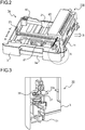
- FIG. 2 is a perspective exterior view, as seen from an upper-front side, of the sheet feeding cassette 1a and a unit support frame 118.
- the description will deal with the configuration of the sheet feeding cassette 1a, and the sheet feeding cassette 1b has completely the same configuration as the sheet feeding cassette 1a.
- the sheet feeding cassette 1a illustrated in FIG. 2 is accommodated in the cassette-type sheet feeding portion 101 of the image forming apparatus 100 illustrated in FIG. 1 .
- a cassette body 10 is formed in a shape of a flat box with an open top, having four walls standing upright along four edges of a bottom, and accommodates sheets P stacked in it from above (see FIG. 1 ).
- a unit support frame 118 Outside a wall positioned on the downstream side with respect to the sheet feeding direction (right side in FIG. 2 ) inside the image forming apparatus 100, above the sheet feeding cassette 1a, there is arranged a unit support frame 118, which is included in the cassette-type sheet feeding portion 101. Sheets P are separated one by one from the stacked sheets P to be fed out in a direction indicated by an arrow B in FIG.
- a cassette cover 3 is formed integrally, and the cassette cover 3 forms a lower-front part of a housing of the image forming apparatus 100.
- a handle 3a which is to be held by the user to detach/attach the sheet feeding cassette 1a.
- a pair of guide rails 11 are attached outside a wall extending in a direction parallel to a direction in which the sheet feeding cassette 1a is inserted or drawn out (AA' direction).
- the body of the image forming apparatus 100 is provided with a pair of rail support portions (not shown) slidably supporting the guide rails 11. By sliding the guide rails 11 along the rail support portions, the sheet feeding cassette 1a can be inserted into and drawn out of the image forming apparatus 100.
- a sheet stacking plate 20 on which to stack sheets P and a pair of width restricting cursors 21 standing upright and extending along the sheet feeding direction (the direction indicated by the arrow B).
- the width restricting cursors 21 make contact with side faces of the stack of sheets from opposite sides in a sheet width direction (the AA' direction) perpendicular to the sheet feeding direction, and serve to position the sheets P in the sheet width direction to keep them in the sheet feed position from which the sheet feeding unit 117a feeds them out.
- the width restricting cursors 21 are movable along a cursor movement groove (not shown) which is provided in an inner surface of the bottom of the cassette body 10 so as to extend in the sheet width direction.
- the pair of width restricting cursors 21, which makes contact with side faces of the stack of sheets P from opposite sides in the sheet width direction, is configured in such a manner that, when one width restricting cursor moves, the other width restricting cursor is caused to move together by an action of an unillustrated interlocking mechanism provided under them.
- the movement of the pair of width restricting cursors 21 is symmetric with respect to a width-direction center line of the sheets P.
- a trailing-end restricting cursor 23 is provided inside the cassette body 10, in an upstream-side part of the cassette body 10 with respect to the sheet feeding direction.
- the trailing-end restricting cursor 23 makes contact with a side face of the stack of sheets P from the upstream side with respect to the sheet feeding direction, and serves to position the sheets in the sheet feeding direction (the direction indicated by the arrow B in FIG. 2 ) to keep them in the sheet feed position from which the sheet feeding device 117 feeds them out.
- the trailing-end restricting cursor 23 is movable along a cursor movement groove (not shown) that is provided in the inner surface of the bottom of the cassette body 10 so as to extend in the sheet feeding direction.
- FIG. 3 is a perspective view of, and around, a lock member 31 disposed at one end (indicated by a broken-line circle S in FIG. 2 ) of a back-surface side of the cassette cover 3.
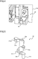
- FIG. 4 is an enlarged perspective view of a locking pin 40 provided in the unit support frame 118 (on the cassette-type sheet feeding portion 101 side).
- FIG. 5 is a perspective view of the lock member 31.
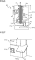
- FIG. 6 is a side sectional view of the lock mechanism 30 in a state where the sheet feeding cassette 1a is inserted in the cassette-type sheet feeding portion 101.
- the lock member 31 is attached to one end of the cassette cover 3, on the back-surface side of the cassette cover 3.
- the lock member 31 is swingably supported by a shaft 35, which is fixed to support portions 33a and 33b of the cassette cover 3.
- the lock member 31 includes a cylindrical body portion 31a having a first through hole 32a through which the shaft 35 is to be inserted, a hook portion 31b protruding from an upper end of the body portion 31a in a diameter direction, a press portion 31c which protrudes from a lower end of the body portion 31a in a direction opposite to the direction in which the hook portion 31b protrudes and which is bent downward, and a crank portion 31d which is U-shaped in side view and via which the body portion 31a and the press portion 31c are connected to each other.
- the crank portion 31d includes a second through hole 32b which is formed coaxial with respect to the first through hole 32a of the body portion 31a.
- the body portion 31a of the lock member 31 is slidably supported by the shaft 35, in a state of being located between the support portions 33a and 33b in an up-down direction.
- the crank portion 31d is arranged avoiding an end of the support portion 33b.
- a lower end part of the shaft 35, which protrudes downward from the support portion 33b, is inserted through the second through hole 32b of the crank portion 31d.
- a distance d1 from an upper end part of the body portion 31a to a lower surface of the support portion 33a is substantially equal to a distance d2 from an upper surface of the crank portion 31d to a lower surface of the support portion 33b. This allows the lock member 31 to move in the up-down direction by the distance d1 (d2) along the shaft 35.
- a coil spring 37 is wound around the lock member 31, with one end of the coil spring 37 fixed to the lock member 31, and with the other end of the coil spring 37 fixed to the support portion 33a.
- the lock member 31 is biased by the coil spring 37 in a constant direction (counterclockwise direction in FIG. 3 ).
- the unit support frame 118 is provided with a locking pin 40, with which the hook portion 31b of the lock member 31 can engage.
- the lock member 31, the shaft 35, the coil spring 37, and the locking pin 40 constitute the lock mechanism 30 of the present disclosure.
- the coil spring 37 biases the lock member 31 in a downward direction as well, and as illustrated in FIG. 6 , a lower end part of the press portion 31c is arranged below an upper end part of the cassette cover 3 of the sheet feeding cassette 1b, which is arranged under the sheet feeding cassette 1a.
- a second inclined portion 31ca is formed on a side surface on the downstream side with respect to the insertion direction of the sheet feeding cassette 1a.
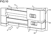
- a release member 50 which is card-shaped (thin plate-shaped), is inserted into a gap G between the cassette cover 3 of the sheet feeding cassette 1a and the cassette cover 3 of the sheet feeding cassette 1b, at one end side (right end side in FIG. 2 ) of the cassette covers 3 where the lock mechanism 30 is provided.
- the release member 50 is not a dedicated member for releasing the lock mechanism 30, and various cards insertable into the gap G, such as an employee ID card and an IC card, can be used as the release member 50.
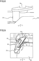
- the release member 50 is slid in a direction indicated by an arrow C, so that an edge of the release member 50 pushes the press portion 31c in the direction indicated by the arrow C as illustrated in FIG. 8 .
- the lock member 31 swings about the shaft 35 in the clockwise direction from the engagement position (indicated by broken lines) to be arranged in a release position (indicated by solid lines) where the engagement of the hook portion 31b with the locking pin 40 is released.
- the press portion 31c makes contact with the inclined surface 39 when the sheet feeding cassette 1a is drawn out.
- the press portion 31c moves onto the cassette cover 3 of the sheet feeding cassette 1b along the inclined surface 39, and this causes the lock member 31 to move upward against the biasing force of the coil spring 37. Thereby, it is possible to avoid interference between the lock member 31 and the sheet feeding cassette 1b which would otherwise be caused in the drawing-out of the sheet feeding cassette 1a.
- the drawing-out of the sheet feeding cassette 1a is restricted (locked) just by inserting the sheet feeding cassette 1a into the cassette-type sheet feeding portion 101, there is no need of providing a lock or the like for locking the sheet feeding cassette 1a, and thus no locking operation is necessary.
- the release member 50 for releasing the lock to draw out the sheet feeding cassette 1a may be any card-shaped member insertable into the gap G, and thus no dedicated key is necessary.
- the sheet feeding cassette 1a can be drawn out just by inserting a card-shaped member into the gap G, and this contributes to improved user-friendliness.
- the lock mechanism 30 is externally invisible and difficult for those other than the user to notice, there is no risk of the sheet feeding cassette 1a being drawn out by a thief. Furthermore, the design properties of the image forming apparatus 100 are improved without any risk of damage to the appearance of the image forming apparatus 100.
- the lock member 31 is also biased in the downward direction by the coil spring 37, and in the state where the sheet feeding cassette 1a is inserted in the cassette-type sheet feeding portion 101, the press portion 31c extends to a position below an upper surface of the cassette cover 3 of the sheet feeding cassette 1b. Thereby, it is possible to securely make an edge of the release member 50 make contact with the press portion 31c when the release member 50 is inserted through the gap G.
- a lock mechanism 30 may be provided in the sheet feeding cassette 1b, too.
- the lock mechanism 30 may be released by inserting the release member 50 into a gap between the cassette cover 3 of the sheet feeding cassette 1b and an external cover 60 located under the cassette cover 3. Further, by forming an inclined surface 39 in the exterior cover 60, it is possible to avoid interference between the lock member 31 and the exterior cover 60 which would otherwise be caused when the sheet feeding cassette 1b is drawn out.
- the present disclosure is not limited to the above embodiments, and various modifications are possible within the scope of the present disclosure.
- the present disclosure is also applicable to image forming apparatuses including only one sheet feeding cassette, or to image forming apparatuses including three or more sheet feeding cassettes.
- the present disclosure is not limited to a monochrome copier as illustrated in FIG. 1 , and applicable to various image forming apparatuses, such as monochrome and color printers, color copiers, and facsimile machines, which are provided with a sheet feeding cassette.
- the present disclosure can be used in image forming apparatuses provided with a sheet storage cassette attached in such a manner that it can be inserted into and drawn out of the image forming apparatuses. Usage of the present disclosure makes it possible to lock a sheet storage cassette with a simple configuration without using a dedicated key, and also to provide an image forming apparatus where an operation to release the locking of the sheet storage cassette is difficult to be found out.
- a description of a method or a method step shall be understood also as a description of means for implementing the respective method or step thereof, and vice versa.
- Features shall be deemed combinable with each other also if their combination is not expressly mentioned, to the extent that the combination is technically feasible.
- Features described in a certain combination, context, embodiment, claim or figure shall be understood as usable also in another combination, context, embodiment, claim or figure, to the extent that this is feasible.
Landscapes
- Engineering & Computer Science (AREA)
- Mechanical Engineering (AREA)
- Physics & Mathematics (AREA)
- General Physics & Mathematics (AREA)
- Sheets, Magazines, And Separation Thereof (AREA)
- Electrophotography Configuration And Component (AREA)
Claims (7)
- Cassette de stockage de feuilles (1a, 1b) comprenant :un corps de cassette (10) apte à être inséré dans une partie d'insertion de cassette (101) d'un corps d'un dispositif de formation d'image (100) et retiré de celle-ci, et lequel accueille une feuille d'un support d'enregistrement ;un couvercle de cassette (3) disposé sur un côté amont du corps de cassette (10) par rapport à une direction d'insertion de corps de cassette (10), et constituant une partie d'un élément extérieur (60) du dispositif de formation d'image ; etun mécanisme de verrouillage (30) maintenant le corps de cassette (10) verrouillé dans un état inséré dans la partie d'insertion de cassette (101),le mécanisme de verrouillage (30) comprenantun élément de verrouillage (31) disposé de façon oscillante sur un côté de surface arrière du couvercle de cassette (3), et apte à être engagé avec une broche de verrouillage (40) disposée dans la partie d'insertion de cassette (101), etun élément de sollicitation (37) sollicitant l'élément de verrouillage (31) dans une direction vers un engagement avec la broche de verrouillage (40),pendant une opération d'insertion du corps de cassette (10) dans la partie d'insertion de cassette (101), l'élément de verrouillage (31) est mis en engagement avec la broche de verrouillage (40) par la force de sollicitation de l'élément de sollicitation (37),caractérisée en ce quedans un état où le corps de cassette (10) est inséré dans la partie d'insertion de cassette (101), en insérant un élément de libération (50) présentant une forme de plaque mince dans un espace entre le corps de cassette (10) et l'élément extérieur (3, 60) disposé sous le corps de cassette (10) et à côté de celui-ci, l'élément de verrouillage (31) est amené à osciller contre la force de sollicitation de l'élément de sollicitation (37), et l'engagement de l'élément de verrouillage (31) avec la broche de verrouillage (40) est libéré.
- Cassette de stockage de feuilles (1a, 1b) selon la revendication 1,
dans laquelle
l'élément de verrouillage (31) comprend
une partie de corps (31a) présentant une forme cylindrique et dans laquelle est inséré un arbre (35) fixé au couvercle de cassette (3),
une partie de crochet (31b) faisant saillie à partir d'une partie supérieure de la partie de corps (31a) dans une direction de diamètre et engageable avec la broche de verrouillage (40), et
une partie de pression (31c) faisant saillie à partir d'une partie inférieure de la partie de corps (31a) dans une direction opposée à la direction dans laquelle la partie de crochet (31b) fait saillie, la partie de pression (31c) étant courbée vers le bas,
l'élément de verrouillage (31) pouvant osciller autour de l'arbre (35) dans une direction horizontale,
dans un état dans lequel la cassette de stockage de feuilles (1a, 1b) est insérée dans la partie d'insertion de cassette (101), l'élément de verrouillage (31) est sollicité par la force de sollicitation de l'élément de sollicitation (37) pour être disposé dans une position d'engagement dans laquelle la partie de crochet (31b) s'engage avec la broche de verrouillage (40),
par la partie de pression (31c) pressée par l'élément de libération (50) inséré dans l'espace, l'élément de verrouillage (31) est amené à osciller contre la force de sollicitation de l'élément de sollicitation (37) vers une position de libération dans laquelle l'engagement de la partie de crochet (31b) avec la broche de verrouillage (40) est libéré. - Cassette de stockage de feuilles (1a, 1b) selon la revendication 2,
dans laquelle
la partie de crochet (31b) comprend une première partie inclinée (31ba) formée sur une partie de celle-ci entrant en contact avec la broche de verrouillage (40) lorsque la cassette de stockage de feuilles (1a, 1b) est insérée dans la partie d'insertion de cassette (101). - Cassette de stockage de feuilles (1a,1b) selon la revendication 2 ou 3,
dans laquelle
l'élément de verrouillage (31) est déplaçable dans une direction de haut en bas le long de l'arbre (35) et l'élément de sollicitation (37) sollicite l'élément de verrouillage (31) dans une direction vers le bas, et conjointement à l'opération d'insertion du corps de cassette (10) dans la portion d'insertion de cassette (101), l'élément de verrouillage (31) passe au-dessus d'une partie d'extrémité supérieure de l'élément extérieur (3, 60) tout en se déplaçant vers le haut en sens opposé à la force de sollicitation de l'élément de sollicitation (37), et dans un état où la cassette de stockage de feuilles est insérée dans la portion d'insertion de cassette (101), une partie d'extrémité inférieure de la partie de pression (31c) est disposée au-dessous de la partie d'extrémité supérieure de l'élément extérieur (3, 60). - Cassette de stockage de feuilles (1a, 1b) selon la revendication 4,
dans laquelle
la partie de pression (31c) inclut une seconde partie inclinée (31ca) formée sur une partie de cette dernière qui vient en contact avec la partie d'extrémité supérieure de l'élément extérieur (3, 60) lorsque la cassette de stockage de feuilles est intégrée dans la portion d'insertion de cassette (101). - Cassette de stockage de feuilles (1a, 1b) selon la revendication 4 ou 5,
dans laquelle
le couvercle de cassette (3) comprend une surface inclinée (39) formée sur une partie de celui-ci entrant en contact avec la partie de pression (31c) de l'élément de verrouillage (31) disposé dans une autre cassette de stockage de feuilles (la) lorsque l'autre cassette de stockage de feuilles (la) disposée sur le couvercle de cassette (3) et adjacente à celui-ci est retirée de la partie d'insertion de cassette (101). - Dispositif de formation d'image (100) comprenant la cassette de stockage de feuilles (1a, 1b) selon l'une quelconque des revendications 1 à 6.
Applications Claiming Priority (1)
| Application Number | Priority Date | Filing Date | Title |
|---|---|---|---|
| JP2016064267A JP6468229B2 (ja) | 2016-03-28 | 2016-03-28 | シート収納カセット及びそれを備えた画像形成装置 |
Publications (2)
| Publication Number | Publication Date |
|---|---|
| EP3228567A1 EP3228567A1 (fr) | 2017-10-11 |
| EP3228567B1 true EP3228567B1 (fr) | 2018-10-03 |
Family
ID=58398048
Family Applications (1)
| Application Number | Title | Priority Date | Filing Date |
|---|---|---|---|
| EP17161820.0A Not-in-force EP3228567B1 (fr) | 2016-03-28 | 2017-03-20 | Cassette de stockage de feuilles et appareil de formation d'image en étant équipé |
Country Status (4)
| Country | Link |
|---|---|
| US (1) | US10146166B2 (fr) |
| EP (1) | EP3228567B1 (fr) |
| JP (1) | JP6468229B2 (fr) |
| CN (1) | CN107235346B (fr) |
Families Citing this family (8)
| Publication number | Priority date | Publication date | Assignee | Title |
|---|---|---|---|---|
| JP6783733B2 (ja) * | 2017-09-19 | 2020-11-11 | 株式会社三共 | 遊技機 |
| JP7031186B2 (ja) * | 2017-09-19 | 2022-03-08 | 富士フイルムビジネスイノベーション株式会社 | 引き込み装置、収容装置、及び画像形成装置 |
| JP6939421B2 (ja) * | 2017-10-30 | 2021-09-22 | 京セラドキュメントソリューションズ株式会社 | 画像形成装置 |
| JP7124311B2 (ja) * | 2017-12-15 | 2022-08-24 | 京セラドキュメントソリューションズ株式会社 | 給送装置、及び画像形成装置 |
| JP7147868B2 (ja) * | 2018-11-13 | 2022-10-05 | 京セラドキュメントソリューションズ株式会社 | シート収容装置、及びシート収容装置を備える画像処理装置、シート位置決め部材 |
| JP7252511B2 (ja) * | 2019-02-07 | 2023-04-05 | 京セラドキュメントソリューションズ株式会社 | プリンタードライバー |
| US12504710B2 (en) * | 2023-10-23 | 2025-12-23 | Ricoh Company, Ltd. | Functional expansion unit, electronic device, and image forming apparatus |
| US12498665B2 (en) * | 2023-10-24 | 2025-12-16 | Ricoh Company, Ltd. | Attachment structure, electronic device, and image forming apparatus |
Family Cites Families (14)
| Publication number | Priority date | Publication date | Assignee | Title |
|---|---|---|---|---|
| US5155537A (en) * | 1988-11-22 | 1992-10-13 | Canon Kabushiki Kaisha | Sheet feeding apparatus with a plurality of easily loaded cassettes |
| JP3263252B2 (ja) * | 1994-08-30 | 2002-03-04 | 東芝エレベータ株式会社 | エレベータ乗場ドアの解錠装置 |
| JPH09290933A (ja) * | 1996-04-26 | 1997-11-11 | Ricoh Co Ltd | 給紙装置 |
| US6942257B2 (en) * | 2001-09-13 | 2005-09-13 | Cosco Management, Inc. | Cabinet latch |
| JP2004308389A (ja) * | 2003-04-07 | 2004-11-04 | Circle Iron Work Co Ltd | セーフティボックス |
| JP2005178942A (ja) * | 2003-12-17 | 2005-07-07 | Ricoh Co Ltd | 給紙装置、及びこれを備えた画像形成装置 |
| JP4678329B2 (ja) | 2006-04-28 | 2011-04-27 | 富士ゼロックス株式会社 | 画像形成装置 |
| JP4410777B2 (ja) * | 2006-06-15 | 2010-02-03 | 株式会社ベスト | 非表示型打掛錠の非常解錠構造 |
| JP4721467B2 (ja) * | 2007-10-26 | 2011-07-13 | キヤノンマーケティングジャパン株式会社 | 画像形成装置、給紙ユニット、及び、給紙トレイの施錠方法 |
| WO2009103933A1 (fr) * | 2008-02-19 | 2009-08-27 | Talaris Holdings Limited | Mécanisme de verrouillage |
| JP2013133214A (ja) | 2011-12-27 | 2013-07-08 | Canon Inc | シート搬送装置および画像形成装置 |
| JP2014148400A (ja) * | 2013-02-01 | 2014-08-21 | Konica Minolta Inc | 給紙装置及び画像形成装置 |
| US9329527B2 (en) * | 2014-07-30 | 2016-05-03 | Kyocera Document Solutions Inc. | Toner case and image forming apparatus including the same |
| TWD188003S (zh) * | 2017-06-14 | 2018-01-21 | 慶良電子股份有限公司 | 電連接器之部分 |
-
2016
- 2016-03-28 JP JP2016064267A patent/JP6468229B2/ja not_active Expired - Fee Related
-
2017
- 2017-02-17 US US15/436,467 patent/US10146166B2/en active Active
- 2017-02-22 CN CN201710096175.0A patent/CN107235346B/zh not_active Expired - Fee Related
- 2017-03-20 EP EP17161820.0A patent/EP3228567B1/fr not_active Not-in-force
Non-Patent Citations (1)
| Title |
|---|
| None * |
Also Published As
| Publication number | Publication date |
|---|---|
| US20170277102A1 (en) | 2017-09-28 |
| JP2017178489A (ja) | 2017-10-05 |
| US10146166B2 (en) | 2018-12-04 |
| JP6468229B2 (ja) | 2019-02-13 |
| EP3228567A1 (fr) | 2017-10-11 |
| CN107235346B (zh) | 2018-11-02 |
| CN107235346A (zh) | 2017-10-10 |
Similar Documents
| Publication | Publication Date | Title |
|---|---|---|
| EP3228567B1 (fr) | Cassette de stockage de feuilles et appareil de formation d'image en étant équipé | |
| US6409165B1 (en) | Sheet holder and sheet trailing edge restriction member therefor | |
| JP5873848B2 (ja) | シート給送装置及びそれを備えた画像形成装置 | |
| JP3116448B2 (ja) | 給紙カセット | |
| US8052141B2 (en) | Recording-medium storage device and image forming apparatus | |
| US9567171B2 (en) | Sheet stackable device and image forming apparatus | |
| US20100172678A1 (en) | Image forming apparatus | |
| EP2371564B1 (fr) | Appareil d'enregistrement | |
| US20150097330A1 (en) | Sheet storage cassette and image forming apparatus including same | |
| JP7130970B2 (ja) | シート収納カセット及びそれを備えたシート給送装置並びに画像形成装置 | |
| US20180179000A1 (en) | Sheet placement apparatus and printing apparatus | |
| JP2009007081A (ja) | 記録媒体収納装置及び画像形成装置 | |
| US9829849B2 (en) | Image forming apparatus | |
| JP2005170575A (ja) | 給紙カセット及びこれを搭載した画像形成装置 | |
| JP4315031B2 (ja) | 給紙カセット | |
| US20080080916A1 (en) | Transport apparatus and image-forming apparatus | |
| JPH08290836A (ja) | 給紙装置 | |
| JP2025022084A (ja) | シート給送装置およびそれを備えた画像形成装置 | |
| US10061261B2 (en) | Coupling mechanism, and sheet feed device and image forming apparatus including same | |
| JP2011090266A (ja) | 複合画像形成装置 | |
| JP4324003B2 (ja) | シート材供給装置および記録装置 | |
| JP3567048B2 (ja) | シート供給装置及び記録装置 | |
| US6311970B1 (en) | Paper feed cassette and image formation apparatus | |
| JP2009149421A (ja) | 給紙トレイと該給紙トレイを装着した給紙装置及び画像形成装置 | |
| JP2010052903A (ja) | 給紙カセット及びこれを備えた画像形成装置 |
Legal Events
| Date | Code | Title | Description |
|---|---|---|---|
| PUAI | Public reference made under article 153(3) epc to a published international application that has entered the european phase |
Free format text: ORIGINAL CODE: 0009012 |
|
| STAA | Information on the status of an ep patent application or granted ep patent |
Free format text: STATUS: THE APPLICATION HAS BEEN PUBLISHED |
|
| AK | Designated contracting states |
Kind code of ref document: A1 Designated state(s): AL AT BE BG CH CY CZ DE DK EE ES FI FR GB GR HR HU IE IS IT LI LT LU LV MC MK MT NL NO PL PT RO RS SE SI SK SM TR |
|
| AX | Request for extension of the european patent |
Extension state: BA ME |
|
| STAA | Information on the status of an ep patent application or granted ep patent |
Free format text: STATUS: REQUEST FOR EXAMINATION WAS MADE |
|
| 17P | Request for examination filed |
Effective date: 20180309 |
|
| RBV | Designated contracting states (corrected) |
Designated state(s): AL AT BE BG CH CY CZ DE DK EE ES FI FR GB GR HR HU IE IS IT LI LT LU LV MC MK MT NL NO PL PT RO RS SE SI SK SM TR |
|
| RIC1 | Information provided on ipc code assigned before grant |
Ipc: G03G 15/00 20060101ALI20180425BHEP Ipc: G03G 21/16 20060101ALI20180425BHEP Ipc: B65H 1/26 20060101AFI20180425BHEP Ipc: B65H 1/04 20060101ALI20180425BHEP |
|
| GRAP | Despatch of communication of intention to grant a patent |
Free format text: ORIGINAL CODE: EPIDOSNIGR1 |
|
| STAA | Information on the status of an ep patent application or granted ep patent |
Free format text: STATUS: GRANT OF PATENT IS INTENDED |
|
| INTG | Intention to grant announced |
Effective date: 20180608 |
|
| GRAS | Grant fee paid |
Free format text: ORIGINAL CODE: EPIDOSNIGR3 |
|
| GRAA | (expected) grant |
Free format text: ORIGINAL CODE: 0009210 |
|
| STAA | Information on the status of an ep patent application or granted ep patent |
Free format text: STATUS: THE PATENT HAS BEEN GRANTED |
|
| AK | Designated contracting states |
Kind code of ref document: B1 Designated state(s): AL AT BE BG CH CY CZ DE DK EE ES FI FR GB GR HR HU IE IS IT LI LT LU LV MC MK MT NL NO PL PT RO RS SE SI SK SM TR |
|
| REG | Reference to a national code |
Ref country code: GB Ref legal event code: FG4D |
|
| REG | Reference to a national code |
Ref country code: CH Ref legal event code: EP Ref country code: AT Ref legal event code: REF Ref document number: 1048356 Country of ref document: AT Kind code of ref document: T Effective date: 20181015 |
|
| REG | Reference to a national code |
Ref country code: IE Ref legal event code: FG4D Ref country code: DE Ref legal event code: R096 Ref document number: 602017000566 Country of ref document: DE |
|
| REG | Reference to a national code |
Ref country code: NL Ref legal event code: MP Effective date: 20181003 |
|
| REG | Reference to a national code |
Ref country code: LT Ref legal event code: MG4D |
|
| REG | Reference to a national code |
Ref country code: AT Ref legal event code: MK05 Ref document number: 1048356 Country of ref document: AT Kind code of ref document: T Effective date: 20181003 |
|
| PG25 | Lapsed in a contracting state [announced via postgrant information from national office to epo] |
Ref country code: NL Free format text: LAPSE BECAUSE OF FAILURE TO SUBMIT A TRANSLATION OF THE DESCRIPTION OR TO PAY THE FEE WITHIN THE PRESCRIBED TIME-LIMIT Effective date: 20181003 |
|
| PG25 | Lapsed in a contracting state [announced via postgrant information from national office to epo] |
Ref country code: HR Free format text: LAPSE BECAUSE OF FAILURE TO SUBMIT A TRANSLATION OF THE DESCRIPTION OR TO PAY THE FEE WITHIN THE PRESCRIBED TIME-LIMIT Effective date: 20181003 Ref country code: LT Free format text: LAPSE BECAUSE OF FAILURE TO SUBMIT A TRANSLATION OF THE DESCRIPTION OR TO PAY THE FEE WITHIN THE PRESCRIBED TIME-LIMIT Effective date: 20181003 Ref country code: LV Free format text: LAPSE BECAUSE OF FAILURE TO SUBMIT A TRANSLATION OF THE DESCRIPTION OR TO PAY THE FEE WITHIN THE PRESCRIBED TIME-LIMIT Effective date: 20181003 Ref country code: NO Free format text: LAPSE BECAUSE OF FAILURE TO SUBMIT A TRANSLATION OF THE DESCRIPTION OR TO PAY THE FEE WITHIN THE PRESCRIBED TIME-LIMIT Effective date: 20190103 Ref country code: FI Free format text: LAPSE BECAUSE OF FAILURE TO SUBMIT A TRANSLATION OF THE DESCRIPTION OR TO PAY THE FEE WITHIN THE PRESCRIBED TIME-LIMIT Effective date: 20181003 Ref country code: AT Free format text: LAPSE BECAUSE OF FAILURE TO SUBMIT A TRANSLATION OF THE DESCRIPTION OR TO PAY THE FEE WITHIN THE PRESCRIBED TIME-LIMIT Effective date: 20181003 Ref country code: CZ Free format text: LAPSE BECAUSE OF FAILURE TO SUBMIT A TRANSLATION OF THE DESCRIPTION OR TO PAY THE FEE WITHIN THE PRESCRIBED TIME-LIMIT Effective date: 20181003 Ref country code: IS Free format text: LAPSE BECAUSE OF FAILURE TO SUBMIT A TRANSLATION OF THE DESCRIPTION OR TO PAY THE FEE WITHIN THE PRESCRIBED TIME-LIMIT Effective date: 20190203 Ref country code: BG Free format text: LAPSE BECAUSE OF FAILURE TO SUBMIT A TRANSLATION OF THE DESCRIPTION OR TO PAY THE FEE WITHIN THE PRESCRIBED TIME-LIMIT Effective date: 20190103 Ref country code: PL Free format text: LAPSE BECAUSE OF FAILURE TO SUBMIT A TRANSLATION OF THE DESCRIPTION OR TO PAY THE FEE WITHIN THE PRESCRIBED TIME-LIMIT Effective date: 20181003 |
|
| PG25 | Lapsed in a contracting state [announced via postgrant information from national office to epo] |
Ref country code: AL Free format text: LAPSE BECAUSE OF FAILURE TO SUBMIT A TRANSLATION OF THE DESCRIPTION OR TO PAY THE FEE WITHIN THE PRESCRIBED TIME-LIMIT Effective date: 20181003 Ref country code: PT Free format text: LAPSE BECAUSE OF FAILURE TO SUBMIT A TRANSLATION OF THE DESCRIPTION OR TO PAY THE FEE WITHIN THE PRESCRIBED TIME-LIMIT Effective date: 20190203 Ref country code: SE Free format text: LAPSE BECAUSE OF FAILURE TO SUBMIT A TRANSLATION OF THE DESCRIPTION OR TO PAY THE FEE WITHIN THE PRESCRIBED TIME-LIMIT Effective date: 20181003 Ref country code: RS Free format text: LAPSE BECAUSE OF FAILURE TO SUBMIT A TRANSLATION OF THE DESCRIPTION OR TO PAY THE FEE WITHIN THE PRESCRIBED TIME-LIMIT Effective date: 20181003 Ref country code: GR Free format text: LAPSE BECAUSE OF FAILURE TO SUBMIT A TRANSLATION OF THE DESCRIPTION OR TO PAY THE FEE WITHIN THE PRESCRIBED TIME-LIMIT Effective date: 20190104 |
|
| REG | Reference to a national code |
Ref country code: DE Ref legal event code: R097 Ref document number: 602017000566 Country of ref document: DE |
|
| PG25 | Lapsed in a contracting state [announced via postgrant information from national office to epo] |
Ref country code: ES Free format text: LAPSE BECAUSE OF FAILURE TO SUBMIT A TRANSLATION OF THE DESCRIPTION OR TO PAY THE FEE WITHIN THE PRESCRIBED TIME-LIMIT Effective date: 20181003 Ref country code: DK Free format text: LAPSE BECAUSE OF FAILURE TO SUBMIT A TRANSLATION OF THE DESCRIPTION OR TO PAY THE FEE WITHIN THE PRESCRIBED TIME-LIMIT Effective date: 20181003 Ref country code: IT Free format text: LAPSE BECAUSE OF FAILURE TO SUBMIT A TRANSLATION OF THE DESCRIPTION OR TO PAY THE FEE WITHIN THE PRESCRIBED TIME-LIMIT Effective date: 20181003 |
|
| PLBE | No opposition filed within time limit |
Free format text: ORIGINAL CODE: 0009261 |
|
| STAA | Information on the status of an ep patent application or granted ep patent |
Free format text: STATUS: NO OPPOSITION FILED WITHIN TIME LIMIT |
|
| PG25 | Lapsed in a contracting state [announced via postgrant information from national office to epo] |
Ref country code: RO Free format text: LAPSE BECAUSE OF FAILURE TO SUBMIT A TRANSLATION OF THE DESCRIPTION OR TO PAY THE FEE WITHIN THE PRESCRIBED TIME-LIMIT Effective date: 20181003 Ref country code: EE Free format text: LAPSE BECAUSE OF FAILURE TO SUBMIT A TRANSLATION OF THE DESCRIPTION OR TO PAY THE FEE WITHIN THE PRESCRIBED TIME-LIMIT Effective date: 20181003 Ref country code: SM Free format text: LAPSE BECAUSE OF FAILURE TO SUBMIT A TRANSLATION OF THE DESCRIPTION OR TO PAY THE FEE WITHIN THE PRESCRIBED TIME-LIMIT Effective date: 20181003 Ref country code: SK Free format text: LAPSE BECAUSE OF FAILURE TO SUBMIT A TRANSLATION OF THE DESCRIPTION OR TO PAY THE FEE WITHIN THE PRESCRIBED TIME-LIMIT Effective date: 20181003 |
|
| 26N | No opposition filed |
Effective date: 20190704 |
|
| PG25 | Lapsed in a contracting state [announced via postgrant information from national office to epo] |
Ref country code: MC Free format text: LAPSE BECAUSE OF FAILURE TO SUBMIT A TRANSLATION OF THE DESCRIPTION OR TO PAY THE FEE WITHIN THE PRESCRIBED TIME-LIMIT Effective date: 20181003 Ref country code: SI Free format text: LAPSE BECAUSE OF FAILURE TO SUBMIT A TRANSLATION OF THE DESCRIPTION OR TO PAY THE FEE WITHIN THE PRESCRIBED TIME-LIMIT Effective date: 20181003 |
|
| PG25 | Lapsed in a contracting state [announced via postgrant information from national office to epo] |
Ref country code: LU Free format text: LAPSE BECAUSE OF NON-PAYMENT OF DUE FEES Effective date: 20190320 |
|
| REG | Reference to a national code |
Ref country code: BE Ref legal event code: MM Effective date: 20190331 |
|
| PG25 | Lapsed in a contracting state [announced via postgrant information from national office to epo] |
Ref country code: IE Free format text: LAPSE BECAUSE OF NON-PAYMENT OF DUE FEES Effective date: 20190320 |
|
| PG25 | Lapsed in a contracting state [announced via postgrant information from national office to epo] |
Ref country code: BE Free format text: LAPSE BECAUSE OF NON-PAYMENT OF DUE FEES Effective date: 20190331 |
|
| PG25 | Lapsed in a contracting state [announced via postgrant information from national office to epo] |
Ref country code: TR Free format text: LAPSE BECAUSE OF FAILURE TO SUBMIT A TRANSLATION OF THE DESCRIPTION OR TO PAY THE FEE WITHIN THE PRESCRIBED TIME-LIMIT Effective date: 20181003 |
|
| PG25 | Lapsed in a contracting state [announced via postgrant information from national office to epo] |
Ref country code: MT Free format text: LAPSE BECAUSE OF NON-PAYMENT OF DUE FEES Effective date: 20190320 |
|
| REG | Reference to a national code |
Ref country code: CH Ref legal event code: PL |
|
| PG25 | Lapsed in a contracting state [announced via postgrant information from national office to epo] |
Ref country code: LI Free format text: LAPSE BECAUSE OF NON-PAYMENT OF DUE FEES Effective date: 20200331 Ref country code: CH Free format text: LAPSE BECAUSE OF NON-PAYMENT OF DUE FEES Effective date: 20200331 |
|
| PG25 | Lapsed in a contracting state [announced via postgrant information from national office to epo] |
Ref country code: CY Free format text: LAPSE BECAUSE OF FAILURE TO SUBMIT A TRANSLATION OF THE DESCRIPTION OR TO PAY THE FEE WITHIN THE PRESCRIBED TIME-LIMIT Effective date: 20181003 |
|
| PG25 | Lapsed in a contracting state [announced via postgrant information from national office to epo] |
Ref country code: HU Free format text: LAPSE BECAUSE OF FAILURE TO SUBMIT A TRANSLATION OF THE DESCRIPTION OR TO PAY THE FEE WITHIN THE PRESCRIBED TIME-LIMIT; INVALID AB INITIO Effective date: 20170320 |
|
| PG25 | Lapsed in a contracting state [announced via postgrant information from national office to epo] |
Ref country code: MK Free format text: LAPSE BECAUSE OF FAILURE TO SUBMIT A TRANSLATION OF THE DESCRIPTION OR TO PAY THE FEE WITHIN THE PRESCRIBED TIME-LIMIT Effective date: 20181003 |
|
| PGFP | Annual fee paid to national office [announced via postgrant information from national office to epo] |
Ref country code: FR Payment date: 20230222 Year of fee payment: 7 |
|
| PGFP | Annual fee paid to national office [announced via postgrant information from national office to epo] |
Ref country code: GB Payment date: 20230222 Year of fee payment: 7 Ref country code: DE Payment date: 20230221 Year of fee payment: 7 |
|
| P01 | Opt-out of the competence of the unified patent court (upc) registered |
Effective date: 20230420 |
|
| REG | Reference to a national code |
Ref country code: DE Ref legal event code: R119 Ref document number: 602017000566 Country of ref document: DE |
|
| GBPC | Gb: european patent ceased through non-payment of renewal fee |
Effective date: 20240320 |
|
| PG25 | Lapsed in a contracting state [announced via postgrant information from national office to epo] |
Ref country code: DE Free format text: LAPSE BECAUSE OF NON-PAYMENT OF DUE FEES Effective date: 20241001 |
|
| PG25 | Lapsed in a contracting state [announced via postgrant information from national office to epo] |
Ref country code: GB Free format text: LAPSE BECAUSE OF NON-PAYMENT OF DUE FEES Effective date: 20240320 |
|
| PG25 | Lapsed in a contracting state [announced via postgrant information from national office to epo] |
Ref country code: FR Free format text: LAPSE BECAUSE OF NON-PAYMENT OF DUE FEES Effective date: 20240331 |
|
| PG25 | Lapsed in a contracting state [announced via postgrant information from national office to epo] |
Ref country code: GB Free format text: LAPSE BECAUSE OF NON-PAYMENT OF DUE FEES Effective date: 20240320 Ref country code: FR Free format text: LAPSE BECAUSE OF NON-PAYMENT OF DUE FEES Effective date: 20240331 Ref country code: DE Free format text: LAPSE BECAUSE OF NON-PAYMENT OF DUE FEES Effective date: 20241001 |