EP3228573A2 - Elektronische sicherheitsvorrichtung mit einer leistungsanordnung - Google Patents
Elektronische sicherheitsvorrichtung mit einer leistungsanordnung Download PDFInfo
- Publication number
- EP3228573A2 EP3228573A2 EP17165080.7A EP17165080A EP3228573A2 EP 3228573 A2 EP3228573 A2 EP 3228573A2 EP 17165080 A EP17165080 A EP 17165080A EP 3228573 A2 EP3228573 A2 EP 3228573A2
- Authority
- EP
- European Patent Office
- Prior art keywords
- power
- component
- elevator
- safety
- operably coupled
- Prior art date
- Legal status (The legal status is an assumption and is not a legal conclusion. Google has not performed a legal analysis and makes no representation as to the accuracy of the status listed.)
- Granted
Links
Images


Classifications
-
- B—PERFORMING OPERATIONS; TRANSPORTING
- B66—HOISTING; LIFTING; HAULING
- B66B—ELEVATORS; ESCALATORS OR MOVING WALKWAYS
- B66B5/00—Applications of checking, fault-correcting, or safety devices in elevators
- B66B5/02—Applications of checking, fault-correcting, or safety devices in elevators responsive to abnormal operating conditions
- B66B5/16—Braking or catch devices operating between cars, cages, or skips and fixed guide elements or surfaces in hoistway or well
- B66B5/18—Braking or catch devices operating between cars, cages, or skips and fixed guide elements or surfaces in hoistway or well and applying frictional retarding forces
-
- B—PERFORMING OPERATIONS; TRANSPORTING
- B66—HOISTING; LIFTING; HAULING
- B66B—ELEVATORS; ESCALATORS OR MOVING WALKWAYS
- B66B5/00—Applications of checking, fault-correcting, or safety devices in elevators
- B66B5/02—Applications of checking, fault-correcting, or safety devices in elevators responsive to abnormal operating conditions
- B66B5/04—Applications of checking, fault-correcting, or safety devices in elevators responsive to abnormal operating conditions for detecting excessive speed
-
- B—PERFORMING OPERATIONS; TRANSPORTING
- B66—HOISTING; LIFTING; HAULING
- B66B—ELEVATORS; ESCALATORS OR MOVING WALKWAYS
- B66B5/00—Applications of checking, fault-correcting, or safety devices in elevators
- B66B5/02—Applications of checking, fault-correcting, or safety devices in elevators responsive to abnormal operating conditions
- B66B5/16—Braking or catch devices operating between cars, cages, or skips and fixed guide elements or surfaces in hoistway or well
- B66B5/18—Braking or catch devices operating between cars, cages, or skips and fixed guide elements or surfaces in hoistway or well and applying frictional retarding forces
- B66B5/22—Braking or catch devices operating between cars, cages, or skips and fixed guide elements or surfaces in hoistway or well and applying frictional retarding forces by means of linearly-movable wedges
-
- B—PERFORMING OPERATIONS; TRANSPORTING
- B66—HOISTING; LIFTING; HAULING
- B66B—ELEVATORS; ESCALATORS OR MOVING WALKWAYS
- B66B7/00—Other common features of elevators
-
- B—PERFORMING OPERATIONS; TRANSPORTING
- B66—HOISTING; LIFTING; HAULING
- B66D—CAPSTANS; WINCHES; TACKLES, e.g. PULLEY BLOCKS; HOISTS
- B66D5/00—Braking or detent devices characterised by application to lifting or hoisting gear, e.g. for controlling the lowering of loads
- B66D5/02—Crane, lift hoist, or winch brakes operating on drums, barrels, or ropes
- B66D5/12—Crane, lift hoist, or winch brakes operating on drums, barrels, or ropes with axial effect
-
- B—PERFORMING OPERATIONS; TRANSPORTING
- B66—HOISTING; LIFTING; HAULING
- B66D—CAPSTANS; WINCHES; TACKLES, e.g. PULLEY BLOCKS; HOISTS
- B66D5/00—Braking or detent devices characterised by application to lifting or hoisting gear, e.g. for controlling the lowering of loads
- B66D5/02—Crane, lift hoist, or winch brakes operating on drums, barrels, or ropes
- B66D5/24—Operating devices
- B66D5/30—Operating devices electrical
Definitions
- the present disclosure is generally related to braking and/or safety systems for elevator systems and, more specifically, an electronic safety device with a power assembly.
- Some machines such as an elevator system, include a safety system to stop the machine when it rotates at excessive speeds or the elevator cab travels at excessive speeds or accelerations.
- Conventional safety systems include an actively applied safety system that requires power from travelling cables to positively actuate the safety mechanism or a passively applied safety system that requires power from travelling cables to maintain the safety system in a hold operating state.
- an elevator system in one aspect, includes a hoistway, an elevator component disposed in the hoistway, and a power assembly disposed in the hoistway.
- the power assembly includes a first power component disposed in the hoistway, the first power component including a first power connection, and a second power component operably coupled to the elevator component; wherein the first power component is configured to provide wireless power to the second power component.
- the elevator component comprises at least one of an elevator car and a counterweight.
- the elevator system further includes an elevator drive operably coupled to the elevator car.
- the second power component is configured to connect to the first power component via a direct connection or an indirect connection.
- the first power component is operably coupled to a power source.
- the second power component includes a second power connection, a power storage device operably coupled to the second power connector, , and a safety actuation controller including a communication module, the safety actuation controller operably coupled to the power storage device.
- the communication module is configured to wirelessly exchange safety signals with the elevator controller.
- the elevator system further includes a guide rail disposed in the hoistway; the guide rail configured to engage the elevator component and direct the course of travel of the elevator component.
- the first power component is operably coupled to the guide rail.
- the elevator system further includes a safety actuation device operably coupled to the elevator component, the safety actuation device configured to engage the guide rail.
- the second power component is operably coupled to the safety actuation device.
- an elevator safety actuation device in one aspect, includes a power component and an electromagnetic component operably connected to the power component, wherein the electromagnetic component is configured generate an actuation or a reset.
- the power component includes a safety actuation controller, a power storage device operably coupled to the safety actuation controller, and a first connector operably coupled to the first power storage device.
- the electronic safety device further includes a magnetic brake disposed adjacent to the electromagnetic component, the magnetic brake configured to move between an engaging position and a non-engaging position based in part on a holding force.
- the safety controller comprises a communication module.
- the communication module is configured to wirelessly receive and transmit safety signals.
- the elevator safety device further includes a second connector configured to engage the first connector.
- the second connector is removable.
- an elevator system comprising:
- the second power component is configured to connect to the first power component via a direct connection or an indirect connection.
- the first power component is operably coupled to a power source.
- the second power component comprises:
- the elevator system preferably further comprises a guide rail disposed in the hoistway; the guide rail configured to engage the elevator component and direct the course of travel of the elevator component.
- the first power component is operably coupled to the guide rail.
- the elevator system preferably further comprises a safety device operably coupled to the elevator component, the safety device configured to engage the guide rail.
- the second power component is operably coupled to the safety device.
- the elevator component comprises at least one of an elevator car and a counterweight.
- the elevator system preferably further comprises an elevator drive operably coupled to the elevator car.
- the communication module is configured to wirelessly exchange safety signals with the elevator controller and/or the elevator component.
- an elevator safety device comprising:
- the electronic or elevator safety device preferably further comprises:
- the safety actuation controller comprises a communication module.
- the communication module is configured to wirelessly receive and transmit safety signals.
- the electronic or elevator safety device preferably further comprises a second connector configured to engage the first connector.
- the second connector is removable.
- FIG. 1 shows an embodiment of an elevator system, generally indicated at 10.
- the elevator system 10 includes an elevator component disposed in a hoistway 16.
- the elevator component includes at least one of an elevator car 12 and a counterweight 20.
- the elevator car 12 suspended by a cable 14 in the hoistway 16.
- the elevator car 12 is guided between car guide rails 18.
- the counterweight 20 is guided between counterweight guide rails 22 and is suspended on an opposite end of the cable 14.
- Movement of the elevator car 12 and counterweight 20 in the hoistway 16 is provided by a motor 24 mounted in a machine room 26.
- the motor 24 rotates a sheave 28 around which the cable 14 extends to raise and lower the elevator car 12.
- An electromechanical brake (not shown) located in the machine room 26, electronic safety actuation devices, car safeties 34, and/or counterweight safeties 36 act to stop elevator car 12 and counterweight 20 if the elevator car 12 or counterweight 20 exceed a set speed as it travels inside the hoistway 16. If the elevator car 12 or counterweight 20 reaches a defined over-speed condition; thus, transmitting a signal to an elevator drive 38, which in turn cuts power to the elevator drive 38 and drops the brake to arrest movement of the sheave 28 and thereby arrest movement of elevator car 12.
- the electronic safety actuation device may then act to actuate either or both of the car safety 34 and counterweight safety 36 to arrest movement of the elevator car 12 and/or counterweight 20.
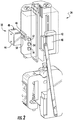
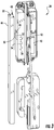
- FIG. 2 shows an embodiment of a power assembly 32 in use with an exemplary electronic safety actuation device that may be employed on the elevator car 12 (i.e., car safety 34) and/or counterweight 20 (i.e., counterweight safety 36).
- the electronic safety actuation device includes an electromagnetic component 40 and a magnetic brake 42. It will be appreciated that the exemplary safety device may include similar components as described below.
- the power assembly 32 is disposed within the hoistway 16.
- the power assembly 32 includes a first power component 44 configured to provide power to a second power component 46, wherein the second power component 46 is disposed on at least one of the elevator car 12 and the counterweight 20.
- the first power component 44 is configured to provide power to the second power component 46 via a direct connection or an indirect connection.
- the first power component 44 may connect to the second power component 46 via a plug and socket connector, inductive charging, conductive charging, wireless power, and/or an outlet to name a few non-limiting examples.
- the first power component 44 includes a first component connector 48
- the second power component 46 includes a second component connector 50, such that when the first component connector 48 and the second component connector 50 are connected, power is transferred from the first power component 44 to the second power component 46.
- the second power component 46 further includes a first power storage device 52 operably coupled to the second component connector 50.
- the first power storage device 52 for example a battery to name one non-limiting example, is further coupled to an electronic safety actuation device controller 54.
- the electronic safety actuation device controller 54 is further coupled to a second power storage device 56.
- the second power storage device 56 for example a capacitor to name one non-limiting example, is further coupled to a portion of the electronic safety actuation device (e.g., the electromagnetic component 40), and is configured to activate the safety actuation device based in part on an actuation command.
- the electronic safety actuation device controller 54 is in communication with the elevator drive 38 via a communication module (not shown) disposed on the electronic safety actuation device controller 54.
- the communication module is configured to wirelessly exchange safety signals with the elevator drive 38. It will be appreciated that the communication module may be separate from the electronic safety actuation controller 54.
- first power component 44 may be disposed within the hoistway 16 and operably coupled to the power source without the need of a traveling cable.
- first power component 44 is disposed at the top of the hoistway 16 on a support adjacent to the car guide rails 18.
- Another first power component 44 may be disposed at the bottom of the hoistway 16 on a support adjacent to the counterweight guide rails 22.
- the counterweight 20 is at the bottom of the hoistway.
- the first power component 44 may be placed at locations along the hoistway 16 corresponding to positions of the counterweight 20 when the elevator car 12 is stopped at each of the floors in the building, or at some subset of floors.
- the first power component 44 may be a power rail to name one non-limiting example.
- the first power component 44 may be disposed in any location, or at multiple locations within the hoistway 16.
- the second power component 46 is operably coupled to a portion of the elevator car 12 and/or counterweight 20 (e.g., the electronic safety actuation device, the car safety 34 and/or the counterweight safety 36).
- the electromagnetic component 40 is a keeper configured to hold the magnetic brake 42 in a non-engaging position without power needed.
- the magnetic brake 42 provides a sufficient magnetic attraction force in a direction toward the electromagnetic component 40 to hold the magnetic brake 42 in the non-engaging position.
- the elevator drive 38 may wirelessly transmit a safety signal to the electronic safety actuation device controller 54 to actuate the electromagnetic component 40.
- the electronic safety actuation device controller 54 may itself sense the overspeed or other condition requiring braking and actuate the electromagnetic component 40.
- the electronic safety actuation device controller 54 may issue an actuation command to the electromagnetic component 40 to propel the magnetic brake 42 towards a guide rail into an engaging position by using the power from the second power storage device 56.
- the exemplary magnetic brake 42 is magnetically attached to the car guide rail 18 (or counterweight guide rails 22).
- the magnetic brake 42 is operably coupled to a safety brake 58 by a rod or small linkage bar 60.
- the magnetic brake 42 in the rail-engaging position, pushes/pulls the safety brake 58 in an upward direction due to the relative upward movement of the magnetic brake 42 relative to the descending elevator car 12.
- the safety brake 58 engages the car guide rail 18 (or counterweight guide rails 22) when the magnetic brake 42 pushes/pulls the safety brake 58 in the upward direction.
- a wedge-shaped portion 62 of the safety brake 58 allows a safety brake pad 64 to move toward and engage with the car guide rail 18 (or counterweight guide rails 22) upon upward movement of the magnetic brake 42 and the rod 60.
- the first power storage device 52 is able to maintain or restore the stored power when the first component connector 48 is connected to the second component connector 50. This is accomplished when the first power component 44 is positioned to be adjacent to the second power component 46 such that the first component connector 48 may engage or mate with the second component connector 50. For example, when the elevator car 12 is stationary at a landing (e.g., top) or running in the hoistway 16, the first power component 44 is positioned to be adjacent to the second power component 46 such that the first component connector 48 may engage or mate with the second component connector 50. Power may then be transferred from the first power component 44 to the first power storage device 52 via the second power connector 50. This arrangement, therefore, eliminates the need for a travelling cable to power the electronic safety actuation device (connected to the car safety 34 and/or connected to the counterweight safety 36).
- the present elevator system 10 includes a power assembly 32 employed on an electronic safety actuation device (connected to car safeties 34, and/or counterweight safeties 36) to actuate the safety without the need of additional traveling cables for power; thus, decreasing the costs of material and installation time of the elevator system 10.
Landscapes
- Engineering & Computer Science (AREA)
- Mechanical Engineering (AREA)
- Automation & Control Theory (AREA)
- Elevator Control (AREA)
- Maintenance And Inspection Apparatuses For Elevators (AREA)
- Structural Engineering (AREA)
- Computer Networks & Wireless Communication (AREA)
Applications Claiming Priority (1)
| Application Number | Priority Date | Filing Date | Title |
|---|---|---|---|
| US15/091,246 US10252884B2 (en) | 2016-04-05 | 2016-04-05 | Wirelessly powered elevator electronic safety device |
Publications (3)
| Publication Number | Publication Date |
|---|---|
| EP3228573A2 true EP3228573A2 (de) | 2017-10-11 |
| EP3228573A3 EP3228573A3 (de) | 2018-03-14 |
| EP3228573B1 EP3228573B1 (de) | 2020-04-29 |
Family
ID=58489644
Family Applications (1)
| Application Number | Title | Priority Date | Filing Date |
|---|---|---|---|
| EP17165080.7A Not-in-force EP3228573B1 (de) | 2016-04-05 | 2017-04-05 | Elektronische sicherheitsvorrichtung mit einer leistungsanordnung |
Country Status (3)
| Country | Link |
|---|---|
| US (1) | US10252884B2 (de) |
| EP (1) | EP3228573B1 (de) |
| CN (1) | CN107434196B (de) |
Families Citing this family (9)
| Publication number | Priority date | Publication date | Assignee | Title |
|---|---|---|---|---|
| US10494227B2 (en) * | 2014-06-12 | 2019-12-03 | Otis Elevator Company | Braking system resetting mechanism for a hoisted structure |
| JP6807753B2 (ja) * | 2014-06-12 | 2021-01-06 | オーチス エレベータ カンパニーOtis Elevator Company | ブレーキ部材駆動機構 |
| US10112803B2 (en) * | 2016-04-01 | 2018-10-30 | Otis Elevator Company | Protection assembly for elevator braking assembly speed sensing device and method |
| US20180162693A1 (en) * | 2016-12-13 | 2018-06-14 | Otis Elevator Company | Speed detection means for elevator or counterweight |
| US11078045B2 (en) * | 2018-05-15 | 2021-08-03 | Otis Elevator Company | Electronic safety actuator for lifting a safety wedge of an elevator |
| EP3604196B1 (de) | 2018-08-03 | 2023-04-26 | Otis Elevator Company | Elektronische sicherheitsbetätigungsanordnung für aufzugssystem |
| EP3617120B1 (de) * | 2018-08-30 | 2024-07-24 | Otis Elevator Company | Steuerung eines elektrischen aufzugssicherheitsaktuators |
| EP3733584A1 (de) * | 2019-05-03 | 2020-11-04 | Otis Elevator Company | Kombinierter sicherheitsbrems- und sicherheitsbetätigungsmechanismus |
| ES2821007B2 (es) * | 2019-09-06 | 2022-02-21 | Orona S Coop | Dispositivo paracaídas electromecánico de aparatos elevadores |
Family Cites Families (35)
| Publication number | Priority date | Publication date | Assignee | Title |
|---|---|---|---|---|
| US4011928A (en) | 1975-06-06 | 1977-03-15 | Westinghouse Electric Corporation | Elevator system |
| CN2036939U (zh) * | 1988-10-16 | 1989-05-03 | 杜立法 | 升降机的安全装置 |
| JP3381350B2 (ja) * | 1993-02-03 | 2003-02-24 | 株式会社日立製作所 | エレベータ用非常止め装置およびエレベータ |
| US5495919A (en) | 1994-04-25 | 1996-03-05 | Otis Elevator Company | Safety brake apparatus for an elevator car or counterweight |
| US5782319A (en) | 1996-02-12 | 1998-07-21 | Montgomery Kone Inc. | Elevator car and counterweight safety |
| US5732795A (en) * | 1996-04-10 | 1998-03-31 | Otis Elevator Company | Power and communication for elevator car without traveling cable |
| US6196355B1 (en) * | 1999-03-26 | 2001-03-06 | Otis Elevator Company | Elevator rescue system |
| ATE333432T1 (de) * | 1999-05-25 | 2006-08-15 | Inventio Ag | Einrichtung zur energieübertragung auf ein fahrzeug eines transportsystems |
| US6457569B2 (en) | 1999-10-27 | 2002-10-01 | Otis Elevator Company | Rotary actuated overspeed safety device |
| JP3857508B2 (ja) * | 2000-08-29 | 2006-12-13 | 株式会社日立製作所 | エレベータ装置 |
| JP3915414B2 (ja) * | 2001-02-21 | 2007-05-16 | 株式会社日立製作所 | エレベーター |
| CA2346519A1 (en) * | 2001-04-30 | 2002-10-30 | Michael J. Beus | Apparatus and method for generating power onboard a hoist conveyance |
| JP4553535B2 (ja) * | 2001-09-28 | 2010-09-29 | 三菱電機株式会社 | エレベータ装置 |
| US6629583B2 (en) * | 2001-12-21 | 2003-10-07 | Otis Elevator Company | Fixture for an elevator system |
| DE50309764D1 (de) | 2002-04-02 | 2008-06-19 | Inventio Ag | Einrichtung zum Einrücken einer Fangvorrichtung für eine Aufzugskabine |
| MY135853A (en) | 2003-02-04 | 2008-07-31 | Inventio Ag | Safety device for an elevator |
| US7097001B2 (en) * | 2003-11-12 | 2006-08-29 | Inventio Ag | Elevator car door movement restrictor |
| CN100455502C (zh) * | 2004-05-27 | 2009-01-28 | 三菱电机株式会社 | 电梯装置 |
| JP4857285B2 (ja) * | 2005-01-11 | 2012-01-18 | オーチス エレベータ カンパニー | エレベータの救出運転を行う方法 |
| CN101146729B (zh) * | 2005-04-01 | 2011-02-02 | 三菱电机株式会社 | 电梯用供电系统 |
| BRPI0601926B1 (pt) * | 2005-06-17 | 2018-06-12 | Inventio Aktiengesellschaft | Dispositivo de pára-quedas do freio |
| KR101130926B1 (ko) * | 2007-03-27 | 2012-03-29 | 미쓰비시덴키 가부시키가이샤 | 엘리베이터의 브레이크 장치 |
| GB2458001B (en) | 2008-01-18 | 2010-12-08 | Kone Corp | An elevator hoist rope, an elevator and method |
| FI121066B (fi) | 2009-03-31 | 2010-06-30 | Kone Corp | Hissijärjestelmä |
| AU2011344433B2 (en) | 2010-12-17 | 2017-03-23 | Inventio Ag | Lift installation comprising car and counterweight |
| CA2821144C (en) | 2010-12-17 | 2019-02-19 | Inventio Ag | Device for actuating and resetting a safety gear |
| US9169104B2 (en) | 2010-12-17 | 2015-10-27 | Inventio Ag | Activating a safety gear |
| PL2788271T3 (pl) | 2011-12-09 | 2015-08-31 | Inventio Ag | Uruchamianie hamulca bezpieczeństwa |
| US9850094B2 (en) | 2011-12-21 | 2017-12-26 | Inventio Ag | Actuator for an elevator brake |
| EP2900582A4 (de) | 2012-09-25 | 2016-09-28 | Otis Elevator Co | Ausgleichsmassnahme für aufzug mit geringem kopfraum oder niedrigem schacht |
| ES2673229T3 (es) | 2012-10-18 | 2018-06-20 | Inventio Ag | Dispositivo de seguridad para una instalación de ascensor |
| US9837860B2 (en) * | 2014-05-05 | 2017-12-05 | Witricity Corporation | Wireless power transmission systems for elevators |
| JP6807753B2 (ja) | 2014-06-12 | 2021-01-06 | オーチス エレベータ カンパニーOtis Elevator Company | ブレーキ部材駆動機構 |
| CN106477430B (zh) * | 2015-09-01 | 2020-11-03 | 奥的斯电梯公司 | 电梯无线通信和电力传送系统 |
| US10315886B2 (en) * | 2016-04-11 | 2019-06-11 | Otis Elevator Company | Electronic safety actuation device with a power assembly, magnetic brake and electromagnetic component |
-
2016
- 2016-04-05 US US15/091,246 patent/US10252884B2/en active Active
-
2017
- 2017-04-05 EP EP17165080.7A patent/EP3228573B1/de not_active Not-in-force
- 2017-04-05 CN CN201710219064.4A patent/CN107434196B/zh not_active Expired - Fee Related
Non-Patent Citations (1)
| Title |
|---|
| None |
Also Published As
| Publication number | Publication date |
|---|---|
| US10252884B2 (en) | 2019-04-09 |
| EP3228573B1 (de) | 2020-04-29 |
| US20170283215A1 (en) | 2017-10-05 |
| CN107434196B (zh) | 2020-09-22 |
| EP3228573A3 (de) | 2018-03-14 |
| CN107434196A (zh) | 2017-12-05 |
Similar Documents
| Publication | Publication Date | Title |
|---|---|---|
| US10252884B2 (en) | Wirelessly powered elevator electronic safety device | |
| US10315886B2 (en) | Electronic safety actuation device with a power assembly, magnetic brake and electromagnetic component | |
| CN106395544B (zh) | 电磁安全触发器 | |
| EP3643666B1 (de) | Aufzugsystem | |
| TWI754429B (zh) | 自推進電梯、電梯制動系統及控制電梯系統的方法 | |
| US10486939B2 (en) | Breaking system for a hoisted structure and method of controlling braking a hoisted structure | |
| EP3331798B1 (de) | Vorrichtung und verfahren zum betätigen einer sicherheitsbremse eines aufzugs | |
| EP2763927B1 (de) | Aufzugsbremssystem | |
| CN104822614A (zh) | 电梯装置 | |
| CN106516931A (zh) | 用于电梯限速器系统和方法的致动器组件 | |
| CN107445013B (zh) | 用于电梯系统的制动系统 | |
| JPWO2003106321A1 (ja) | 釣合錘 | |
| EP4400466B1 (de) | Notstoppsystem für aufzug | |
| EP3666703B1 (de) | Stromübertragung an aufzugssystemkabinen | |
| EP3587327B1 (de) | Elektromagnetische führung für elektronischen sicherheitsauslöser | |
| EP3929130B1 (de) | Sicherheitsverbindung mit einer rolle | |
| CN205419394U (zh) | 一种升降机用电气控制紧急驻停保护装置 |
Legal Events
| Date | Code | Title | Description |
|---|---|---|---|
| PUAI | Public reference made under article 153(3) epc to a published international application that has entered the european phase |
Free format text: ORIGINAL CODE: 0009012 |
|
| STAA | Information on the status of an ep patent application or granted ep patent |
Free format text: STATUS: THE APPLICATION HAS BEEN PUBLISHED |
|
| AK | Designated contracting states |
Kind code of ref document: A2 Designated state(s): AL AT BE BG CH CY CZ DE DK EE ES FI FR GB GR HR HU IE IS IT LI LT LU LV MC MK MT NL NO PL PT RO RS SE SI SK SM TR |
|
| AX | Request for extension of the european patent |
Extension state: BA ME |
|
| REG | Reference to a national code |
Ref country code: DE Ref legal event code: R079 Ref document number: 602017015490 Country of ref document: DE Free format text: PREVIOUS MAIN CLASS: B66B0005040000 Ipc: B66B0005220000 |
|
| PUAL | Search report despatched |
Free format text: ORIGINAL CODE: 0009013 |
|
| AK | Designated contracting states |
Kind code of ref document: A3 Designated state(s): AL AT BE BG CH CY CZ DE DK EE ES FI FR GB GR HR HU IE IS IT LI LT LU LV MC MK MT NL NO PL PT RO RS SE SI SK SM TR |
|
| AX | Request for extension of the european patent |
Extension state: BA ME |
|
| RIC1 | Information provided on ipc code assigned before grant |
Ipc: B66B 7/00 20060101ALI20180206BHEP Ipc: B66B 5/22 20060101AFI20180206BHEP |
|
| STAA | Information on the status of an ep patent application or granted ep patent |
Free format text: STATUS: REQUEST FOR EXAMINATION WAS MADE |
|
| 17P | Request for examination filed |
Effective date: 20180911 |
|
| RBV | Designated contracting states (corrected) |
Designated state(s): AL AT BE BG CH CY CZ DE DK EE ES FI FR GB GR HR HU IE IS IT LI LT LU LV MC MK MT NL NO PL PT RO RS SE SI SK SM TR |
|
| GRAP | Despatch of communication of intention to grant a patent |
Free format text: ORIGINAL CODE: EPIDOSNIGR1 |
|
| STAA | Information on the status of an ep patent application or granted ep patent |
Free format text: STATUS: GRANT OF PATENT IS INTENDED |
|
| INTG | Intention to grant announced |
Effective date: 20191217 |
|
| GRAS | Grant fee paid |
Free format text: ORIGINAL CODE: EPIDOSNIGR3 |
|
| GRAA | (expected) grant |
Free format text: ORIGINAL CODE: 0009210 |
|
| STAA | Information on the status of an ep patent application or granted ep patent |
Free format text: STATUS: THE PATENT HAS BEEN GRANTED |
|
| AK | Designated contracting states |
Kind code of ref document: B1 Designated state(s): AL AT BE BG CH CY CZ DE DK EE ES FI FR GB GR HR HU IE IS IT LI LT LU LV MC MK MT NL NO PL PT RO RS SE SI SK SM TR |
|
| REG | Reference to a national code |
Ref country code: GB Ref legal event code: FG4D |
|
| REG | Reference to a national code |
Ref country code: CH Ref legal event code: EP |
|
| REG | Reference to a national code |
Ref country code: DE Ref legal event code: R096 Ref document number: 602017015490 Country of ref document: DE |
|
| REG | Reference to a national code |
Ref country code: AT Ref legal event code: REF Ref document number: 1263013 Country of ref document: AT Kind code of ref document: T Effective date: 20200515 |
|
| REG | Reference to a national code |
Ref country code: IE Ref legal event code: FG4D |
|
| REG | Reference to a national code |
Ref country code: NL Ref legal event code: MP Effective date: 20200429 |
|
| REG | Reference to a national code |
Ref country code: LT Ref legal event code: MG4D |
|
| PG25 | Lapsed in a contracting state [announced via postgrant information from national office to epo] |
Ref country code: IS Free format text: LAPSE BECAUSE OF FAILURE TO SUBMIT A TRANSLATION OF THE DESCRIPTION OR TO PAY THE FEE WITHIN THE PRESCRIBED TIME-LIMIT Effective date: 20200829 Ref country code: FI Free format text: LAPSE BECAUSE OF FAILURE TO SUBMIT A TRANSLATION OF THE DESCRIPTION OR TO PAY THE FEE WITHIN THE PRESCRIBED TIME-LIMIT Effective date: 20200429 Ref country code: PT Free format text: LAPSE BECAUSE OF FAILURE TO SUBMIT A TRANSLATION OF THE DESCRIPTION OR TO PAY THE FEE WITHIN THE PRESCRIBED TIME-LIMIT Effective date: 20200831 Ref country code: NO Free format text: LAPSE BECAUSE OF FAILURE TO SUBMIT A TRANSLATION OF THE DESCRIPTION OR TO PAY THE FEE WITHIN THE PRESCRIBED TIME-LIMIT Effective date: 20200729 Ref country code: SE Free format text: LAPSE BECAUSE OF FAILURE TO SUBMIT A TRANSLATION OF THE DESCRIPTION OR TO PAY THE FEE WITHIN THE PRESCRIBED TIME-LIMIT Effective date: 20200429 Ref country code: LT Free format text: LAPSE BECAUSE OF FAILURE TO SUBMIT A TRANSLATION OF THE DESCRIPTION OR TO PAY THE FEE WITHIN THE PRESCRIBED TIME-LIMIT Effective date: 20200429 Ref country code: GR Free format text: LAPSE BECAUSE OF FAILURE TO SUBMIT A TRANSLATION OF THE DESCRIPTION OR TO PAY THE FEE WITHIN THE PRESCRIBED TIME-LIMIT Effective date: 20200730 |
|
| REG | Reference to a national code |
Ref country code: AT Ref legal event code: MK05 Ref document number: 1263013 Country of ref document: AT Kind code of ref document: T Effective date: 20200429 |
|
| PG25 | Lapsed in a contracting state [announced via postgrant information from national office to epo] |
Ref country code: BG Free format text: LAPSE BECAUSE OF FAILURE TO SUBMIT A TRANSLATION OF THE DESCRIPTION OR TO PAY THE FEE WITHIN THE PRESCRIBED TIME-LIMIT Effective date: 20200729 Ref country code: HR Free format text: LAPSE BECAUSE OF FAILURE TO SUBMIT A TRANSLATION OF THE DESCRIPTION OR TO PAY THE FEE WITHIN THE PRESCRIBED TIME-LIMIT Effective date: 20200429 Ref country code: LV Free format text: LAPSE BECAUSE OF FAILURE TO SUBMIT A TRANSLATION OF THE DESCRIPTION OR TO PAY THE FEE WITHIN THE PRESCRIBED TIME-LIMIT Effective date: 20200429 Ref country code: RS Free format text: LAPSE BECAUSE OF FAILURE TO SUBMIT A TRANSLATION OF THE DESCRIPTION OR TO PAY THE FEE WITHIN THE PRESCRIBED TIME-LIMIT Effective date: 20200429 |
|
| PG25 | Lapsed in a contracting state [announced via postgrant information from national office to epo] |
Ref country code: NL Free format text: LAPSE BECAUSE OF FAILURE TO SUBMIT A TRANSLATION OF THE DESCRIPTION OR TO PAY THE FEE WITHIN THE PRESCRIBED TIME-LIMIT Effective date: 20200429 Ref country code: AL Free format text: LAPSE BECAUSE OF FAILURE TO SUBMIT A TRANSLATION OF THE DESCRIPTION OR TO PAY THE FEE WITHIN THE PRESCRIBED TIME-LIMIT Effective date: 20200429 |
|
| PG25 | Lapsed in a contracting state [announced via postgrant information from national office to epo] |
Ref country code: AT Free format text: LAPSE BECAUSE OF FAILURE TO SUBMIT A TRANSLATION OF THE DESCRIPTION OR TO PAY THE FEE WITHIN THE PRESCRIBED TIME-LIMIT Effective date: 20200429 Ref country code: ES Free format text: LAPSE BECAUSE OF FAILURE TO SUBMIT A TRANSLATION OF THE DESCRIPTION OR TO PAY THE FEE WITHIN THE PRESCRIBED TIME-LIMIT Effective date: 20200429 Ref country code: DK Free format text: LAPSE BECAUSE OF FAILURE TO SUBMIT A TRANSLATION OF THE DESCRIPTION OR TO PAY THE FEE WITHIN THE PRESCRIBED TIME-LIMIT Effective date: 20200429 Ref country code: RO Free format text: LAPSE BECAUSE OF FAILURE TO SUBMIT A TRANSLATION OF THE DESCRIPTION OR TO PAY THE FEE WITHIN THE PRESCRIBED TIME-LIMIT Effective date: 20200429 Ref country code: IT Free format text: LAPSE BECAUSE OF FAILURE TO SUBMIT A TRANSLATION OF THE DESCRIPTION OR TO PAY THE FEE WITHIN THE PRESCRIBED TIME-LIMIT Effective date: 20200429 Ref country code: CZ Free format text: LAPSE BECAUSE OF FAILURE TO SUBMIT A TRANSLATION OF THE DESCRIPTION OR TO PAY THE FEE WITHIN THE PRESCRIBED TIME-LIMIT Effective date: 20200429 Ref country code: SM Free format text: LAPSE BECAUSE OF FAILURE TO SUBMIT A TRANSLATION OF THE DESCRIPTION OR TO PAY THE FEE WITHIN THE PRESCRIBED TIME-LIMIT Effective date: 20200429 Ref country code: EE Free format text: LAPSE BECAUSE OF FAILURE TO SUBMIT A TRANSLATION OF THE DESCRIPTION OR TO PAY THE FEE WITHIN THE PRESCRIBED TIME-LIMIT Effective date: 20200429 |
|
| REG | Reference to a national code |
Ref country code: DE Ref legal event code: R097 Ref document number: 602017015490 Country of ref document: DE |
|
| PG25 | Lapsed in a contracting state [announced via postgrant information from national office to epo] |
Ref country code: PL Free format text: LAPSE BECAUSE OF FAILURE TO SUBMIT A TRANSLATION OF THE DESCRIPTION OR TO PAY THE FEE WITHIN THE PRESCRIBED TIME-LIMIT Effective date: 20200429 Ref country code: SK Free format text: LAPSE BECAUSE OF FAILURE TO SUBMIT A TRANSLATION OF THE DESCRIPTION OR TO PAY THE FEE WITHIN THE PRESCRIBED TIME-LIMIT Effective date: 20200429 |
|
| PLBE | No opposition filed within time limit |
Free format text: ORIGINAL CODE: 0009261 |
|
| STAA | Information on the status of an ep patent application or granted ep patent |
Free format text: STATUS: NO OPPOSITION FILED WITHIN TIME LIMIT |
|
| 26N | No opposition filed |
Effective date: 20210201 |
|
| PG25 | Lapsed in a contracting state [announced via postgrant information from national office to epo] |
Ref country code: SI Free format text: LAPSE BECAUSE OF FAILURE TO SUBMIT A TRANSLATION OF THE DESCRIPTION OR TO PAY THE FEE WITHIN THE PRESCRIBED TIME-LIMIT Effective date: 20200429 |
|
| PG25 | Lapsed in a contracting state [announced via postgrant information from national office to epo] |
Ref country code: MC Free format text: LAPSE BECAUSE OF FAILURE TO SUBMIT A TRANSLATION OF THE DESCRIPTION OR TO PAY THE FEE WITHIN THE PRESCRIBED TIME-LIMIT Effective date: 20200429 |
|
| GBPC | Gb: european patent ceased through non-payment of renewal fee |
Effective date: 20210405 |
|
| PG25 | Lapsed in a contracting state [announced via postgrant information from national office to epo] |
Ref country code: LU Free format text: LAPSE BECAUSE OF NON-PAYMENT OF DUE FEES Effective date: 20210405 |
|
| REG | Reference to a national code |
Ref country code: BE Ref legal event code: MM Effective date: 20210430 |
|
| PG25 | Lapsed in a contracting state [announced via postgrant information from national office to epo] |
Ref country code: LI Free format text: LAPSE BECAUSE OF NON-PAYMENT OF DUE FEES Effective date: 20210430 Ref country code: CH Free format text: LAPSE BECAUSE OF NON-PAYMENT OF DUE FEES Effective date: 20210430 Ref country code: GB Free format text: LAPSE BECAUSE OF NON-PAYMENT OF DUE FEES Effective date: 20210405 |
|
| PG25 | Lapsed in a contracting state [announced via postgrant information from national office to epo] |
Ref country code: IE Free format text: LAPSE BECAUSE OF NON-PAYMENT OF DUE FEES Effective date: 20210405 |
|
| PG25 | Lapsed in a contracting state [announced via postgrant information from national office to epo] |
Ref country code: BE Free format text: LAPSE BECAUSE OF NON-PAYMENT OF DUE FEES Effective date: 20210430 |
|
| PGFP | Annual fee paid to national office [announced via postgrant information from national office to epo] |
Ref country code: FR Payment date: 20230321 Year of fee payment: 7 |
|
| PG25 | Lapsed in a contracting state [announced via postgrant information from national office to epo] |
Ref country code: HU Free format text: LAPSE BECAUSE OF FAILURE TO SUBMIT A TRANSLATION OF THE DESCRIPTION OR TO PAY THE FEE WITHIN THE PRESCRIBED TIME-LIMIT; INVALID AB INITIO Effective date: 20170405 |
|
| PG25 | Lapsed in a contracting state [announced via postgrant information from national office to epo] |
Ref country code: CY Free format text: LAPSE BECAUSE OF FAILURE TO SUBMIT A TRANSLATION OF THE DESCRIPTION OR TO PAY THE FEE WITHIN THE PRESCRIBED TIME-LIMIT Effective date: 20200429 |
|
| PGFP | Annual fee paid to national office [announced via postgrant information from national office to epo] |
Ref country code: DE Payment date: 20230321 Year of fee payment: 7 |
|
| PG25 | Lapsed in a contracting state [announced via postgrant information from national office to epo] |
Ref country code: MK Free format text: LAPSE BECAUSE OF FAILURE TO SUBMIT A TRANSLATION OF THE DESCRIPTION OR TO PAY THE FEE WITHIN THE PRESCRIBED TIME-LIMIT Effective date: 20200429 |
|
| PG25 | Lapsed in a contracting state [announced via postgrant information from national office to epo] |
Ref country code: MT Free format text: LAPSE BECAUSE OF FAILURE TO SUBMIT A TRANSLATION OF THE DESCRIPTION OR TO PAY THE FEE WITHIN THE PRESCRIBED TIME-LIMIT Effective date: 20200429 |
|
| REG | Reference to a national code |
Ref country code: DE Ref legal event code: R119 Ref document number: 602017015490 Country of ref document: DE |
|
| PG25 | Lapsed in a contracting state [announced via postgrant information from national office to epo] |
Ref country code: DE Free format text: LAPSE BECAUSE OF NON-PAYMENT OF DUE FEES Effective date: 20241105 |
|
| PG25 | Lapsed in a contracting state [announced via postgrant information from national office to epo] |
Ref country code: FR Free format text: LAPSE BECAUSE OF NON-PAYMENT OF DUE FEES Effective date: 20240430 |
|
| PG25 | Lapsed in a contracting state [announced via postgrant information from national office to epo] |
Ref country code: FR Free format text: LAPSE BECAUSE OF NON-PAYMENT OF DUE FEES Effective date: 20240430 Ref country code: DE Free format text: LAPSE BECAUSE OF NON-PAYMENT OF DUE FEES Effective date: 20241105 |
|
| PG25 | Lapsed in a contracting state [announced via postgrant information from national office to epo] |
Ref country code: TR Free format text: LAPSE BECAUSE OF FAILURE TO SUBMIT A TRANSLATION OF THE DESCRIPTION OR TO PAY THE FEE WITHIN THE PRESCRIBED TIME-LIMIT Effective date: 20200429 |